1
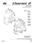
iVacuum 34™
Operating instructions (ENG)
MODELS:
CV34
10125650
CV34X
10125790
Read these instructions before using the machine.
86347810-T
02/09/12
Machine Data/Overview
OVERVIEW
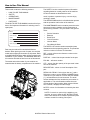
The Chariot® iVacuum 34™ is a battery powered, stand-on, wide area vacuum intended for commercial use. The
Chariot® iVacuum 34™ brushes and vacuums debris from the floor and stores it in the debris tray and vacuum
bags.
Warranty Registration
Thank you for purchasing a Windsor product. Warranty registration is quick and easy.
Your registration will allow us to serve you better over the lifetime of the product.
To register your product go to :
www.windsorind.com/WarrantyRegistration.aspx
For customer assistance:
1-800-444-7654
2
86347810 Chariot iVacuum 34
Table of Contents
Machine Data/Overview . . . . . . . . . . . . . . . . . . . . . . 2
Table of Contents . . . . . . . . . . . . . . . . . . . . . . . . . . . 3
How to Use This Manual . . . . . . . . . . . . . . . . . . . . . . 4
Safety
IMPORTANT SAFETY INSTRUCTIONS . . . . . . . . . . 5
Hazard Intensity Level . . . . . . . . . . . . . . . . . . . . . . . 6
Safety Label Location . . . . . . . . . . . . . . . . . . . . . . . . 7
Operations
Technical Specifications . . . . . . . . . . . . . . . . . . . . . . 8
How This machine Works . . . . . . . . . . . . . . . . . . . . 10
Components . . . . . . . . . . . . . . . . . . . . . . . . . . . . . . 11
Drive Controls . . . . . . . . . . . . . . . . . . . . . . . . . . . . . 12
Deck Controls . . . . . . . . . . . . . . . . . . . . . . . . . . . . . 16
Pre-run Machine Inspection . . . . . . . . . . . . . . . . . . 17
Emergency Stop Procedures . . . . . . . . . . . . . . . . . 17
Normal Vacuuming . . . . . . . . . . . . . . . . . . . . . . . . . 18
To Begin Vacuuming. . . . . . . . . . . . . . . . . . . . . . . . 18
To Stop Vacuuming . . . . . . . . . . . . . . . . . . . . . . . . 19
Changing Vacuum Bag . . . . . . . . . . . . . . . . . . . . . . 19
Maintenance
Service Schedule . . . . . . . . . . . . . . . . . . . . . . . . . . 20
Batteries . . . . . . . . . . . . . . . . . . . . . . . . . . . . . . . . . 21
Battery Maintenance . . . . . . . . . . . . . . . . . . . . . . . . 22
Checking Battery Specific Gravity. . . . . . . . . . . . . . 23
Charging Batteries . . . . . . . . . . . . . . . . . . . . . . . . . 23
Changing Batteries . . . . . . . . . . . . . . . . . . . . . . . . . 24
Brush Deck . . . . . . . . . . . . . . . . . . . . . . . . . . . . . . . 25
Brush Removal . . . . . . . . . . . . . . . . . . . . . . . . . . . . 26
Brush Installation . . . . . . . . . . . . . . . . . . . . . . . . . . 26
To Replace Brush Motor . . . . . . . . . . . . . . . . . . . . . 27
Brush Motor Carbon Brush Replacement . . . . . . . . 27
Circuit Breakers . . . . . . . . . . . . . . . . . . . . . . . . . . . 28
Vacuum Motor Carbon Brush Replacement . . . . . . 29
To Remove Vacuum Motor . . . . . . . . . . . . . . . . . . . 29
Electric Parking Brake Engagement . . . . . . . . . . . . 31
Drive Motor Carbon Brush Replacement . . . . . . . . 32
Brake Removal . . . . . . . . . . . . . . . . . . . . . . . . . . . . 32
Pushing Machine . . . . . . . . . . . . . . . . . . . . . . . . . . 33
Machine Tie-downs. . . . . . . . . . . . . . . . . . . . . . . . . 33
Preparation for Loading/Unloading Trailer . . . . . . . 33
Troubleshooting . . . . . . . . . . . . . . . . . . . . . . . . . . . 34
Propel Circuit Board Troubleshooting . . . . . . . . . . . 35
Parts
Brush Deck - Debris Tray . . . . . . . . . . . . . . . . . . . 38
Brush Deck Drive . . . . . . . . . . . . . . . . . . . . . . . . . 40
Brush Deck . . . . . . . . . . . . . . . . . . . . . . . . . . . . . . 42
Brush Deck Linkage . . . . . . . . . . . . . . . . . . . . . . . 44
Brush Deck Mounting . . . . . . . . . . . . . . . . . . . . . . 46
Brush Deck Linkage Mounting . . . . . . . . . . . . . . . 48
Brush Deck Lift . . . . . . . . . . . . . . . . . . . . . . . . . . . 50
Bumper . . . . . . . . . . . . . . . . . . . . . . . . . . . . . . . . . 52
Control Panel . . . . . . . . . . . . . . . . . . . . . . . . . . . . 54
Control Panel Housing . . . . . . . . . . . . . . . . . . . . . 56
Decal . . . . . . . . . . . . . . . . . . . . . . . . . . . . . . . . . . . 58
Frame-lower . . . . . . . . . . . . . . . . . . . . . . . . . . . . . 60
Frame-Upper. . . . . . . . . . . . . . . . . . . . . . . . . . . . . 62
Hood . . . . . . . . . . . . . . . . . . . . . . . . . . . . . . . . . . . 64
Pedal Platform . . . . . . . . . . . . . . . . . . . . . . . . . . . 66
Pedal Platform Mounting. . . . . . . . . . . . . . . . . . . . 68
Rear Cover . . . . . . . . . . . . . . . . . . . . . . . . . . . . . . 70
Side Broom . . . . . . . . . . . . . . . . . . . . . . . . . . . . . . 72
Steering. . . . . . . . . . . . . . . . . . . . . . . . . . . . . . . . . 74
Vacuum . . . . . . . . . . . . . . . . . . . . . . . . . . . . . . . . . 76
Wheel-Front Drive-Gear . . . . . . . . . . . . . . . . . . . . 78
Wheel-Front Drive Brake . . . . . . . . . . . . . . . . . . . 80
Wheel-Rear . . . . . . . . . . . . . . . . . . . . . . . . . . . . . . 82
Wiring-Batteries . . . . . . . . . . . . . . . . . . . . . . . . . . 84
Wiring-Components . . . . . . . . . . . . . . . . . . . . . . . 86
Wiring-Control Panel . . . . . . . . . . . . . . . . . . . . . . . 88
Wiring-Drive Motor . . . . . . . . . . . . . . . . . . . . . . . . 90
Wiring-Main Harness . . . . . . . . . . . . . . . . . . . . . . 92
Wiring-Pedal Platform . . . . . . . . . . . . . . . . . . . . . . 94
Wiring Diagram . . . . . . . . . . . . . . . . . . . . . . . . . . . 96
Suggested Spare Parts . . . . . . . . . . . . . . . . . . . . . 97
Back-Up Alarm-Option . . . . . . . . . . . . . . . . . . . . . 98
Battery Cart-Option . . . . . . . . . . . . . . . . . . . . . . . 100
Seat-Option . . . . . . . . . . . . . . . . . . . . . . . . . . . . . 104
Warning Light-Option . . . . . . . . . . . . . . . . . . . . . 106
Serial Numbers . . . . . . . . . . . . . . . . . . . . . . . . . . 108
86347810 Chariot iVacuum 34
3
How to Use This Manual
The SAFETY section contains important information
regarding hazard or unsafe practices of the machine.
Levels of hazards are identified that could
This manual contains the following sections:
•
•
•
•
•
HOW TO USE THIS MANUAL
SAFETY
OPERATIONS
MAINTENANCE
PARTS LIST
result in product or personal injury, or severe injury
resulting in death.
The HOW TO USE THIS MANUAL section will tell you
how to find important information for ordering correct
repair parts.
Model:
The OPERATIONS section is to familiarize the operator
with the operation and function of the machine.
The MAINTENANCE section contains preventive maintenance to keep the machine and its components in
good working condition. They are listed in this general
order:
•
•
•
•
•
•
Date of Purchase:
Serial Number:
Dealer:
Address:
Phone Number:
Sales Representative:
Parts may be ordered from authorized Windsor
dealers. When placing an order for parts, the machine
model and machine serial number are important. Refer
to the MACHINE DATA box which is filled out during the
installation of your machine. The MACHINE DATA box
is located on the inside of the front cover of this manual.
The model and serial number of your machine are
located below the battery compartment of the machine.
Service Schedule
Batteries
Brush Deck
Circuit Protection
Vacuum Motor
Drive Motor & Brake
The PARTS LIST section contains assembled parts
illustrations and corresponding parts list. The parts lists
include a number of columns of information:
REF - column refers to the reference number on the
parts illustration.
PART NO. - column lists the part number for the part.
PRV NO. - reference number.
QTY - column lists the quantity of the part used in that
area of the machine.
DESCRIPTION - column is a brief description of the
part.
SERIAL NO. FROM - If this column has an (*) and a
Reference number, see the SERIAL NUMBERS page
in the back of your manual. If column has two asterisk
(**), call manufacturer for serial number. The serial
number indicates the first machine the part number is
applicable to. The main illustration shows the most
current design of the machine. When a boxed illustration is shown, it displays the older design.
NOTES - column for information not noted by the other
columns.
NOTE: If a service or option kit is installed on your
machine, be sure to keep the KIT INSTRUCTIONS
which came with the kit. It contains replacement parts
numbers needed for ordering future parts
4
86347810 Chariot iVacuum 34
Safety
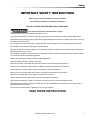
IMPORTANT SAFETY INSTRUCTIONS
When using an electrical appliance, basic precaution
must always be followed, including the following:
READ ALL INSTRUCTIONS BEFORE USING THIS MACHINE.
To reduce the risk of fire, electric shock, or injury:
Use only indoors. Do not use outdoors or expose to rain.
Use only as described in this manual. Use only manufacturer's recommended components and attachments.
If the machine is not working properly, has been dropped, damaged, left outdoors, or dropped into water, return it to
an authorized service center.
Do not operate the machine with any openings blocked. Keep openings free of debris that may reduce airflow.
This machine is not suitable for picking up hazardous dust.
Machine can cause a fire when operating near flammable vapors or materials. Do not operate this machine near
flammable fluids, dust or vapors.
This machine is suitable for commercial use, for example in hotels, schools, hospitals, factories, shops and offices
for more than normal housekeeping purposes.
Maintenance and repairs must be done by qualified personnel.
Disconnect battery before cleaning or servicing.
Before the machine is discarded, the batteries must be removed and properly disposed of.
Make sure all warning and caution labels are legible and properly attached to the machine.
During operation, attention shall be paid to other persons, especially children.
Before use all covers and doors shall be put in the positions specified in the instructions.
When leaving unattended, secure against unintentional movement.
The machine shall only be operated by instructed and authorized persons.
When leaving unattended, switch off or lock the main power switch to prevent unauthorized use.
This appliance has been designed for use with the brushes specified by the manufacturer. The fitting of other
brushes may affect its safety.
Do not use on surfaces having a gradient of over 10% (6 degrees).
SAVE THESE INSTRUCTIONS
86347810 Chariot iVacuum 34
5
Safety
The following symbols are used throughout this guide as indicated in their descriptions:
HAZARD INTENSITY LEVEL
There are three levels of hazard intensity identified by signal words -WARNING and CAUTION and FOR SAFETY.
The level of hazard intensity is determined by the following definitions:
WARNING - Hazards or unsafe practices which COULD result in severe personal injury or death.
CAUTION - Hazards or unsafe practices which could result in minor personal injury or product or property damage.
FOR SAFETY: To Identify actions which must be followed for safe operation of equipment.
Report machine damage or faulty operation immediately. Do not use the machine if it is not in proper operating
condition. Following is information that signals some potentially dangerous conditions to the operator or the equipment. Read this information carefully. Know when these conditions can exist. Locate all safety devices on the
machine. Please take the necessary steps to train the machine operating personnel.
FOR SAFETY:
DO NOT OPERATE MACHINE:
Unless Trained and Authorized.
Unless Operation Guide is Read and understood.
In Flammable or Explosive areas.
In areas with possible falling objects.
WHEN SERVICING MACHINE:
Avoid moving parts. Do not wear loose clothing; jackets, shirts, or sleeves when working on the machine. Use
Windsor approved replacement parts.
Batteries emit hydrogen gas. Explosion or fire can result. Keep sparks and open flame away. Keep
solution tank in raised position when charging. Keep sparks and flames away from the batteries. Do not
smoke around batteries.
Disconnect batteries before working on machine. Only qualified personnel should work inside machine.
Always wear eye protection and protective clothing when working on or near batteries. Avoid skin contact
with the acid contained in the batteries.
Never allow metal to lie across battery tops.
6
86347810 Chariot iVacuum 34
Safety
Safety Label Location
These drawings indicate the location of safety labels on the machine. If at any time the labels become illegible,
promptly replace them.
86244310
PRV NO. 500956
CAUTION LABEL
86252520
PRV NO. 80885
BATTERY
CAUTION
86243830 (2)
PRV NO. 500663
86347810 Chariot iVacuum 34
7
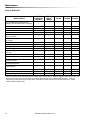
Operations
Technical Specifications
ITEM
Nominal Power
Rated Voltage
Rated Amperage
Batteries
Battery Compartment Dimensions
Propelling Motor
Brush Motor
Side Broom Motor
Bag Capacity (HEPA)
Hopper Capacity
Brushes
Side Broom
Brush Speed
Side Broom Speed
Vacuum Motor
Maximum flow rate of vacuum motor
Suction of vacuum motor with new HEPA bag.
Vacuum bag full shut off
Maximim suction of vacuum motor
Weight (GVW) Gross Weight Batteries
Weight Empty Without Batteries
Tires
Foundation Pressure
Maximum Speed
Frame Construction
Brake
Minimum Aisle
Maximum Rated Climb And Descent Angle
Sound Pressure level at operator’s ear (IEC 60704-1)
Sound Power (IEC 60704-1)
Vibration Hands (ISO 5349)
Vibration Feet (ISO 5349)
8
DIMENSION/CAPACITY
1548 W
36 Volts DC
43 amps
3 X12 Volt 195-215 AH @ 20 hr. rate
21 in. x 16 in. x 17 in. tall (533mm x 406mm x 432mm)
0.75 HP (560 W)
0.5 HP (373 W)
0.06 HP ( 47W)
1019 in³ (16.7 L)
54.9in³ (0.93 Liters)
Two 28 in. (71 cm) by 4 in. (10 cm) diameter
13 in (33 cm)
1125 RPM
90 RPM
0.75 HP (560 W)
200 cfm (95 liters per second)
4.8 inches of water (1.19 kPa)
14-16 inches of water (3.5-4.0 kPa)
23-26 inches of water (5.7-6.5 kPa)
1035 lbs (470 kg)
467 lbs (212 kg)
10 in. (254mm) Solid Gray non-marking
79 psi (544 kPa)
3.5 miles/hour (5.7 Km/hour)
Powder coated steel
Electrical parking brake, sets automatically whenever
operator steps off platform or engages emergency stop.
U-Turn Width 61 in. (1550 mm)
10.0 degrees
69.7 dBA Uncertainty 3.0 dBA
84.3 dBA Uncertainty 3.0 dBA
1.32 m/sec² Uncertainty 0.5 m/sec²
0.52 m/sec² Uncertainty 0.5 m/sec²
86347810 Chariot iVacuum 34
Operations
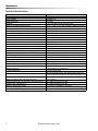
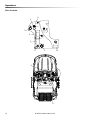
ITEM
MEASURE
Height
50.6 inches (1285 mm)
Length
52.5 inches (1330 mm)
Width without deck
26.5 inches (670 mm)
Width of deck
32.0 inches (813 mm)
Width with side broom
34.5 inches (876 mm)
LENGTH
WIDTH
HEIGHT
This appliance is not intended for use by persons (including children) with reduced physical, sensory or mental
capabilities, or lack of experience and knowledge, unless they have been given supervision or instruction
concerning use of the appliance by a person responsible for their safety. Children should be supervised to ensure
that they do not play with the appliance.
86347810 Chariot iVacuum 34
9
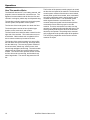
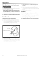
Operations
How This machine Works
The Chariot® iVacuum 34™ is a battery powered, selfpropelled, vacuum intended for commercial use. The
appliance vacuums debris and dirt from the floor and
collects it in a hopper, pdebris tray and disposable bag.
The machine's primary systems are the brush system,
vacuum system, and operator control system.
The function of the brush system is to brush the floor.
The brush system consists of two cylindrical type
brushes, motor, brush deck, and controls.
The front brush turns clockwise when viewed from the
right side of the machine. The rear brush turns counterclockwise. Both brushes work to agitate the floor
and to route the debris up into the brush deck.
The function of the operator control system is to control
the direction and speed of the machine. The directional
control system consists of the direction control switch,
throttle pedal, speed control switch, drive reset switch,
emergency stop/brake switch, steering wheel, propel
controller and drive wheel. The directional control
switch signals forward or reverse direction. The
controller interprets signals from the throttle pedal to
command the drive wheel to propel or slow the
machine. The drive reset switch is to make sure the
operator is on platform before machine will propel. The
steering wheel points the drive wheel in the direction
desired by the operator. The parking brake automatically engages when the operator steps off the platform.
The emergency stop/brake can be used to hold the
machine on slopes.
The function of the vacuum system is to vacuum fine
dirt and debris into the vacuum bag, and large debris
into the debris tray. The recovery system consists of
the vacuum deck, debris tray, vacuum motor, cloth
vacuum bag and paper vacuum bag. The vacuum deck
captures the dirt off the floor as the machine moves
forward. The vacuum motor provides suction to draw
the fine dirt into the vacuum bag, and the debris tray
stores large debris. The vacuum bag stores the fine
dirt.
10
86347810 Chariot iVacuum 34
Operations
9
3
1
7
12
4
5
6
8
11
10
13
2
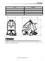
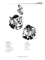
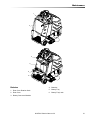
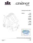
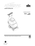
Components
8. Deck Lift
1. Bag Access Lid
9. Paper Bag
2. Brush Deck
10. Pedal Platform
3. Cloth Bag
11. Rear Cover
4. Control Panel-Drive
12. Cover
5. Control Panel-Vacuum
13. Side Broom
6. Control Housing
7. Cover Lid
86347810 Chariot iVacuum 34
11
Operations
Drive Controls
9
2
7
1
5
2
3
3
6
10
1
8
4
12
86347810 Chariot iVacuum 34
Operations
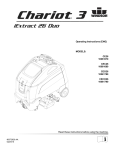
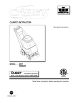
1. Key Switch
6. Drive Reset Button
2. Emergency Stop/Brake Switch
7. Horn Button
3. Directional Control Switch
8. Steering Wheel
4. Throttle Pedal
9. Battery Discharge Indicator
5. Speed Control Switch
10. Hour Meter
1. KEY SWITCH
Controls the power for machine functions.
To turn the machine power on, rotate key clockwise.
To turn the machine off, rotate key counterclockwise.
2. EMERGENCY STOP/BRAKE SWITCH
This safety feature is designed to cut all power to the machine at any time and apply parking brake.
To shut the machine power off, push the Emergency Stop Switch, this will also engage the parking brake and
cause the machine to stop immediately.
To reset the machine, rotate the switch clockwise.
3. DIRECTIONAL CONTROL SWITCH
Controls the direction of travel of the vehicle. The position of the switch indicates direction of travel.
To travel forward, press the top of the switch.
To travel in reverse, press the bottom of the switch.
4.
THROTTLE PEDAL
Controls the speed of the vehicle within the speed control setting selected. Pressing the pedal causes the
machine to travel in the direction selected by the Directional Control Switch.
To increase speed, increase pressure on the pedal.
To decrease speed, decrease pressure on the pedal.
86347810 Chariot iVacuum 34
13
Operations
5. SPEED CONTROL SWITCH
Controls the maximum speed of the machine. Speed 1 is intended for vacuuming. Speeds 2 and 3 are recommended for transport only, not vacuuming.
To increase speed, press the top of the switch.
To decrease speed, press bottom of the switch. Speeds can be adjusted at any time, whether machine is
moving or not.
6. DRIVE RESET SWITCH
This safety feature is designed to ensure safe engagement of propel drive. Each time the machine power is
turned on, and each time an operator steps on to the platform, the Drive Reset Switch must be pushed before
machine will propel.
7. HORN BUTTON
The horn is activated by pressing the horn button.
8. STEERING WHEEL
The steering wheel turns the front wheel causing the machine to change direction.
14
86347810 Chariot iVacuum 34
Operations
9. BATTERY DISCHARGE INDICATOR
Indicates the charge level of the batteries.
The meter display is divided into 10 vertical bars. Bars illuminated on the far right indicate full charge. Bars
flashing near the left side indicate the batteries should be recharged. Further operation of the machine could
damage the machine or the batteries. Bars flashing near left side also indicate that machine has been left unattended with key on for more that 15 minutes. Turn key off then on to reset.
When the machine is left overnight with less than a full charge, the display may initially indicate a full charge. It
will also indicate a full charge if the batteries are disconnected, then reconnected. After a few minutes of
operation the meter will give the correct charge level.
10. HOUR METER
Records the number of hours the machine has been in operation. This information is useful in determining
when to service the machine.
86347810 Chariot iVacuum 34
15
Operations
Brush Lift Lever
Deck Controls
Brush Lift Lever
Raises and lowers the brush deck, side broom and turns the vacuum motor on and off.
To lower brush deck and start vacuum motor and brushes, lift the lever from its raised position.
To raise brush deck and stop vacuum motor and brushes, lift the lever from its lowered position.
16
86347810 Chariot iVacuum 34
Operations
Pre-run Machine Inspection
Emergency Stop Procedures
Do a pre-run inspection to find possible problems that
could cause poor performance or lost time from breakdown. Follow the same procedure each time to avoid
missing steps.
1. Release the throttle pedal by lifting right foot.
NOTE: See maintenance section for pre-run machine
inspection checklist items.
STARTING MACHINE
2. Turn machine power off with key switch by turning
key switch counterclockwise.
3. If an electrical problem is suspected, push in
emergency stop button. This will also engage the
parking brake and cause the machine to stop
immediately.
NOTE: Perform pre-run machine check before
operating machine.
FOR SAFETY: Before starting machine, make sure
that all safety devices are in place and operating
properly.
1. Stand on the operator platform. Throttle pedal must
be in neutral position.
2. Turn the machine power on by turning key switch
clockwise to the "ON" position.
3. Check the position of the Directional Control
Switch to make sure the machine will travel in the
direction intended.
4. Press the Drive Reset Switch.
5. Press lightly on the throttle pedal with right foot.
86347810 Chariot iVacuum 34
17
Operations
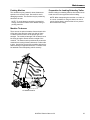
Normal Vacuuming
To Begin Vacuuming
Plan the vacuuming pattern in advance. The longest
track is around the perimeter of the area to be cleaned.
For efficient operation, the runs should be the longest
possible without turning or stopping.
In order to achieve the best possible results, the area
which is to be cleaned should be picked up before
vacuuming. Large debris, strings and wire must be
removed to prevent being caught in brushes.
If machine is allowed to stand in neutral with the
vacuum deck down for more than 2 seconds, the brush
motor stops. If either forward or reverse travel is
selected, the brush motor will continue once movement
of machine begins. Overlap the brush path and avoid
transporting over previously cleaned areas.
When operating the machine around people, pay
close attention for unexpected movement. Use
extra caution around children.
1. Stand on the operator platform. Throttle pedal must
be in neutral position.
2. Turn machine power on.
3. Check position of Directional Control Switch to
ensure that machine is set to travel in direction
intended.
4. Press the Drive Reset Switch.
5. Lower the Brush Deck.
6. Drive machine forward to begin vacuuming.
Recommended Path
18
7. Adjust the speed of the machine as necessary.
86347810 Chariot iVacuum 34
Operations
To Stop Vacuuming
6. Remove cloth bag lip from nozzle.
1. Raise the brush deck, which turns off brushes and
vacuum.
7. Remove cloth band and paper bag together from
vacuum box.
2. Allow the throttle pedal to return to neutral.
8. Remove paper bag from cloth bag and dispose of
properly.
3. Turn machine power off.
FOR SAFETY: Before leaving or servicing machine:
stop on level surface, turn off machine and remove key.
FOR SAFETY: When using machine, go slow on
inclines.
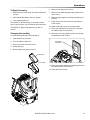
Changing Vacuum Bag
A convenient bag storage is built into the lid.
9. Clean vacuum box and remove any debris from
inside screen.
10. Shake cloth bag to remove any extra debris.
11. Place cloth bag back into vacuum box and push
the rubber collar over the nozzle.
12. Retrieve a new clean paper bag from the storage
compartment in the cover lid.
1. Park machine on level area.
2. Turn the machine power off.
EXTRA BAG
STORAGE
3. Open cover lid and vacuum box lid.
4. Unzip cloth bag.
5. Remove paper bag lip from nozzle.
PAPER BAG
CLOTH BAG
13. Place a new paper bag into the cloth bag and push
the rubber collar over the nozzle.
14. Close all lids and covers.
86347810 Chariot iVacuum 34
19
Maintenance
Service Schedule
MAINTENANCE
Check water level of batteries after
charging; add distilled water if necessary
Check that the vacuum box lid seal tightly
Visually check for damaged or worn tires.
Check vacuum hose connections.
Check hoses for debris buildup.
Check pedal(s), brake and steering for
proper operation
Check vacuum bag fullness and change if
necessary.
Clean brushes and check wear.
Empty debris tray
Charge batteries.
Clean off top of batteries.
Check battery cells with hydrometer. (Wet
cell only)
Check battery connections are tight.
Clean battery cases and compartment.
Clean and check drive tension chain for
wear and tension.
Check parking brake.
Clean chains, cables and pulleys for
brush deck lift.
Check all motors for carbon brush wear.
Check motor commutators.
Check steering chain tensioner.
BEFORE
AFTER EACH
EACH WORK
WORK
PERIOD
PERIOD
50 HRS
100 HRS
200 HRS
*
*
*
*
*
*
*
*
*
*
*
*
*
*
*
*
*
*
*
*
NOTE: A Vacuum hose cleaning brush is included with your vacuum. If debris is caught in the vacuum hose, use
brush to clear the vacuum hose. Remove vacuum bag and clear hose of debris with the brush. It may be
necessary to clear the hose at vacuum shoe connection. Disconnect vacuum hose and clear hose. Check
vacuum shoe for debris also.
20
86347810 Chariot iVacuum 34
Maintenance
1
2
3
4
6
5
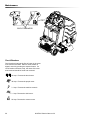
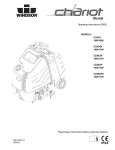
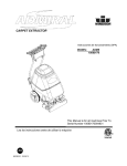
Batteries
4. Batteries
1. Rear Cover Retainer Knob
5. Battery Tray
2. Rear Cover
6. Battery Tray Latch
3. Battery Connector-Machine
86347810 Chariot iVacuum 34
21
Maintenance
Batteries (Wet Cell Only)
The batteries provide the power to operate the
machine. The batteries require regular maintenance to
keep them operating at peak efficiency.
When servicing machine, avoid contact with
battery acid.
The machine batteries will hold their charge for long
periods of time, but they can only be charged a certain
number of times. To get the greatest life from the
batteries, charge them when their charge level reaches
25% of a full charge. Use a hydrometer to check the
charge level.
Batteries emit hydrogen gas. Explosion or fire can
result. Keep sparks and open flame away. Keep
covers open when charging.
Do not allow the batteries to remain in a discharged
condition for any length of time. Never expose a
discharged battery to temperatures below freezing.
Discharged batteries will freeze causing cracked
cases. Do not operate the machine if the batteries are
in poor condition or if they have a charge level below
25% (specific gravity below 1.155).
Keep all metallic objects off the top of the batteries, as
they may cause a short circuit. Replace worn or
damaged cables and terminals.
Check the electrolyte level in each battery cell before
and after charging the batteries. Never add acid to the
batteries, use distilled water. Do not allow water level
to fall below the battery plates. Portions of plates
exposed to air will be destroyed. Do not overfill. Keep
plugs firmly in place at all times.
Wear eye protection and protective clothing when
working with batteries.
Charge batteries in a well ventilated area.
Battery Maintenance
1. When cleaning the batteries, use a solution of
baking soda and water. Do not allow the cleaning
fluid to enter the battery cells, electrolyte will be
neutralized.
2. Maintain the proper electrolyte level in each battery
cell. If a cell should accidentally overflow, clean
immediately.
3. Wipe off the top of the batteries at least once a
week.
4. Test battery condition with a hydrometer at least
once a week.
5. Ensure that all connections are tight and all
corrosion removed.
6. Every 4 to 6 months, remove that batteries from
the machine and clean the battery cases and
battery compartment.
22
86347810 Chariot iVacuum 34
Maintenance
Checking Battery Specific Gravity
Charging Batteries
Use a hydrometer to check the battery specific gravity.
When servicing machine, avoid contact with
battery acid.
Batteries emit hydrogen gas. Explosion or fire can
result. Keep sparks and open flame away. Keep
covers open when charging.
Wear eye protection and protective clothing when
working with batteries.
NOTE: Do not take readings immediately after adding
distilled water, if the water and acid are not
thoroughly mixed, the reading may not be accurate.
Check the hydrometer readings against this chart.
Charge batteries in a well ventilated area.
Use a 36 volt, 20 amp maximum output DC charger
which will automatically shut off when the batteries are
fully charged.
1. Empty recovery tank.
SPECIFIC GRAVITY @
80° F (27°C)
BATTERY CONDITION
1.265
100% CHARGED
1.225
75% CHARGED
1.190
50% CHARGED
1.155
25% CHARGED
1.120
DISCHARGED
2. Stop the machine in a clean, well ventilated area
next to the charger.
3. Turn "OFF" machine.
NOTE: If the readings are taken when the battery
electrolyte is any temperature other than 80°F (27°C),
the reading must be temperature corrected.
To find the corrected specific gravity reading when the
temperature of the battery electrolyte is other than 80°F
(27°): Add (+) to the specific gravity reading 0.004 (4
points), for each 10°F (6°C) above 80° (27°C).
Subtract (-) from the specific reading 0.004 (4 points),
for each 10°F (6°C) below 80°F (27°C).
FOR SAFETY: Before leaving or servicing
machine; stop on level surface, turn off machine
and remove key.
4. 3.Remove rear cover, unplug batteries from
machine, unlatch battery tray and pull out to
expose batteries.
Batteries emit hydrogen gas. Explosion or fire can
result. Keep sparks and open flame away. Keep
covers open when charging.
5. Check the electrolyte level in each battery cell.
Before charging, add just enough distilled water to
cover the plates. After charging is complete, add
just enough distilled water to bring up the level to
the indicator ring. If the water level is too high
before charging, normal expansion rate of the electrolyte may cause an overflow resulting in a loss of
battery acid balance and damage the machine.
NOTE: Battery Charger must be approved to
60335-2-29 standard.
86347810 Chariot iVacuum 34
23
Maintenance
5. Replace the battery caps, and leave them in place
while charging.
6. Unplug the battery connector from the machine.
SAFTEY: When charging, connect the charger to the
batteries before connecting the charger to the AC
wall outlet. Never connect the charger to the AC wall
outlet first. Hazardous sparks may result.
Changing Batteries
Stop the machine in a clean area next to the charger.
Turn off machine.
SAFETY: Before leaving or servicing the machine;
stop on level surface, turn off machine and remove
key.
1. Remove the rear cover.
7. Plug the charger connector into the battery
connector. Connect the charger AC plug to a wall
outlet. The charger gauge should indicate that the
batteries are charging.
2. Disconnect battery pack from machine.
3. Unlatch battery tray from machine and pull out to
expose batteries.
8. When the batteries are fully charged, disconnect
the charger from the AC wall outlet, then disconnect the charger from the batteries.
4. Use the proper size open end wrench to disconnect main ground wire first and secure cable
terminal away from batteries.
9. Connect the batteries to the machine connector.
5. Disconnect main positive lead and secure cable
terminals away from batteries.
10. Check the electrolyte level. It should be up to the
indicator ring. If necessary, add distilled water.
11. Install the rear cover.
6. Loosen both terminals on each jumper cable and
remove one at a time.
7. Prepare a suitable site to place the batteries.
8. Attach suitable battery lifting device and lift
batteries from the machine.
Batteries are a potential environmental hazard.
Consult your battery supplier for safe disposal
methods.
RED
+
BLK
-
RED
+
BLK
-
RED
+
BLK
-
REAR OF MACHINE
24
86347810 Chariot iVacuum 34
Maintenance
5
1
4
2
3
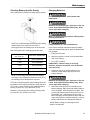
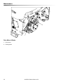
Brush Deck
1. Brush Deck Lift Cable
2. Brush Door
3. Brush Motor
4. Side Broom
5. Side Broom Lift Cable
86347810 Chariot iVacuum 34
25
Maintenance
Brush Deck
Debris Tray Removal
The dual cylindrical head is designed to agitate the
carpet while vacuuming. The first scrubbing brush
turns in a clockwise rotation when viewed from the right
of operator's side of machine. The first brush scrubs
dirt and debris between the brushes. The second
brush, turns in a counter clockwise rotation, picks up
debris and throws it into the debris tray.
1. Release the debris tray spring clip.
NOTE: The brushes should wear evenly side to side.
Brushes should be replaced as a set when bristle
length wears to height of yellow PerformAlert™
bristles.
2. Secure with debris tray spring clip.
2. Slide the debris tray away from machine.
Debris Tray Installation
1. Slide the debris tray into the debris tray mount
notch.
Brush Removal
The brushes are removed from the right side of the
machine.
1. Release door spring clips and rotate the brush door
up.
2. Slide the brushes out the side opening.
SPRING CLIP
Brush Installation
1. Slide brush through door opening and onto drive
shaft. Make sure it is fully seated and is driven by
the deck system.
2. Rotate the brushes until the indicator lines on the
ends are vertical.
3. Rotate the brush door down and secure with spring
clips.
SPRING CLIP
VERTICAL INDICATOR LINE
26
SPRING CLIP
86347810 Chariot iVacuum 34
Maintenance
Brush Motor Carbon Brush Replacement
Do not use a pressure washer to clean around the
brush motors. Use tap pressure only.
1. Scribe alignment mark on motor barrel to motor
cap. Remove two bolts.
2. Remove end cap from motor.
NOTE: Motors contain two wave washers in cap. Do
not lose these.
To Replace Brush Motor
3. With the scrub deck in the lowered position,
disconnect brush motor wiring connector from
harness.
4. Remove the drive housing
5. Remove six (6) motor mount screws.
6. Remove motor with attached coupler, leaving front
motor mounting bracket still attached to deck.
7. Remove coupler from old motor for reuse.
8. Inspect spider coupler for wear replace as needed.
9. Reverse process to reassemble with new motor.
3. Release brush from spring tension. Remove screw
connecting brush wire lead to brush holder. Clean
brush holder to insure free movement.
4. Retract spring and install new brush. Install
connector screw and lead.
5. When all new brushes are installed. Place all in
retracted position, held into brush holder by spring
tension.
6. Carefully place end cap onto bearing on motor
shaft.
NOTE: Use care to assure wave washer alignment.
7. With end cap in partially installed position, release
all brushes to contact position with motor commutator.
NOTE: Failure to insure all brushes are released will
result in motor failure.
8. Reset end cap and realign with scribe marks on
motor barrel. Reinstall the two attach bolts from
cap into base.
9. Maintain alignment between motor barrel base and
cap.
86347810 Chariot iVacuum 34
27
Maintenance
CIRCUIT BREAKERS
Circuit Breakers
Circuit breakers interrupt the flow of power in the event
of an electrical overload. When a circuit breaker is
tripped, reset it by pressing the exposed button. If a
circuit breaker continues to trip, the cause of the electrical overload should be found and corrected.
22 Amp. Protects the brush motor.
30 Amp. Protects the propel motor.
3 Amp. Protects the machine controls.
3 Amp. Protects the side broom.
22 Amp. Protects the vacuum motor.
28
86347810 Chariot iVacuum 34
Maintenance
To Remove Vacuum Motor
Disconnect batteries before working on machine. Only
qualified personnel should work inside machine.
Always wear eye protection and protective clothing
when working on or near batteries. Avoid skin contact
with the acid contained in the batteries.
1. Remove rear cover.
2. Remove two screws from top of control panel and
four screws from side of control panel housing.
3. Slide control housing back from tank to expose
main cover bolts.
1. Remove rear cover from machine.
4. Remove four bolts in front of console from cover,
and 2 bolts from the bottom front of main cover,
and two inside, next to batteries.
2. Remove batteries from machine.
5. Remove main cover.
3. Remove 4 bolts holding access cover in place and
remove cover.
6. Remove four bolts from vacuum motor and disconnect plug.
4. Pull top clips from vacuum motor top brush
retainers.
7. Reverse steps to assemble
Vacuum Motor Carbon Brush Replacement
5. Remove and inspect brushes.
6. Replace both if either is less than 3/8" (9.5 mm)
long.
7. Reverse steps to assemble.
86347810 Chariot iVacuum 34
29
Maintenance
2
1
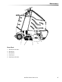
Drive Motor & Brake
1. Drive motor
2. Parking brake
30
86347810 Chariot iVacuum 34
Maintenance
Electric Parking Brake Engagement
To disengage brake:
SAFETY: Before leaving or servicing machine, stop
on a level surface, turn off machine and remove key.
Electric Brake Engagement
This machine is equipped with an electric parking
brake.
The brake automatically engages and keeps the
machine from moving whenever the operator steps off
the platform or when emergency stop is engaged.
The brake has a mechanical over-ride that can be
engaged so machine can be pushed or towed (slowly).
When the mechanical over-ride is engaged the
machine cannot be driven.
To engage brake:
1. Mechanical over-ride disengaged
2. Machine can be driven.
3. Push lever firmly in direction of arrow.
1. Mechanical over-ride engaged.
2. Machine can be pushed or towed (slowly).
Push lever firmly in direction of arrow
NOTE: There is an intermediate stop. Make sure
lever is fully in the down position.
86347810 Chariot iVacuum 34
31
Maintenance
Drive Motor Carbon Brush Replacement
Do not use a pressure washer to clean around the
motors. Use tap pressure only.
SAFETY: Before leaving or servicing machine, stop
on a level surface, turn off machine and remove key.
1. Disconnect batteries from machine.
2. Disconnect the electrical connection to the traction
motor.
7. Install new brush and reinstall connecting screw
and lead.
8. When all new brushes are installed. Place all in
retracted position, held into brush holder by spring
tension.
9. Carefully replace brush cap.
Reinstalling:
10. When replacing the hex hub, use a small pin or
screw to help align the holes.
Brake Removal
11. Drive the pin into the hub and make sure it is flush
to the hex surface. The brake will not fit on the hub
if the roll pin is protruding from the hub.
(Must be done to access carbon brushes)
12. Replace the hub and use Lock-Tite on the screws.
3. Remove 4 mounting screws and remove brake.
4. Drive roll pin out of the hex hub enough to allow
hex hub to slide off shaft. It is recommended that
the roll pin be left partially in the hex hub.
ROLL PIN
HEX HUB
SMALL PIN OR SCREW
5. Remove brush cap.
6. Release brush from spring tension. Remove screw
connecting brush wire lead to brush holder. Clean
brush holder to insure free movement.
32
86347810 Chariot iVacuum 34
Maintenance
Pushing Machine
Preparation for Loading/Unloading Trailer
The machine may be pushed for short distances at
speeds not to exceed 5 mph. Be careful to avoid
damaging machine. The machine may be pushed by
hand from the rear.
Before loading or unloading machine from trailer, brush
head must be in the up position before loading.
NOTE: To avoid damage caused by regenerative
voltage, disconnect traction motor before towing or
pushing machine.
NOTE: When transporting the machine on a trailer or
in a truck, in addition to using tie-downs, be sure to
set the parking brake, and block the tires to prevent
the machine from rolling
Machine Tie-downs
There are two tie points located at front and each side
of foot box frame and two at the front side of frame.
Tie-down devices must be of the proper type and
strength. The combined strength of all tie-downs must
be strong enough to lift two times the weight of the
machine. Tie-downs must be positioned to prevent the
machine from moving forward, backward, or either side
to side. Use all four corners of the machine with the tiedowns running out opposite directions. Tie-downs must
be attached to the transporting vehicle securely.
TIE DOWN POINTS
86347810 Chariot iVacuum 34
33
Maintenance
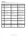
Troubleshooting
PROBLEM
No power to machine
Little or no propel
CAUSE
Battery disconnected
Emergency shut-off activated
Faulty key switch
Low battery charge
Machine turned on with pedal not in
neutral position
Tripped circuit breaker
Controller overheated
Faulty drive reset circuit or switch
Faulty platform circuit or switch
Brake over-ride engaged
Faulty brake circuit or over-ride switch
Faulty speed control circuit or switch
Check wires, connections and switch
Faulty forward/reverse switch
Replace Switch
Circuit breaker tripped
Reset
Full bag or clog in system (bag full light
on)
Replace bag, check for and remove debris
Debris caught in system
Remove debris
Low battery charge
Charge batteries
Bag full light on
Replace bag or remove clog
Circuit breaker(s) tripped
Low battery charge
Fault brush circuit or motor
Reset circuit breaker(s)
Charge battery
Check wires, connections and motor
Faulty throttle circuit or potentiometer
Reverse speed only
Vacuum and brush do
not turn on
Poor vacuums
performance
Brush motors do no run,
or run slowly
34
Allow pedal to return to neutral. Restart
Reset circuit breaker and check brush
Allow cool down period
Check wires and connections from
controller to motor
Check wires and connections from throttle
to controller and potentiometer resistance
Check wires, connection and switch
Check wires, connections and switch
Disengage brake over-ride
Check wires, connections and switch
Loose motor connection
Machine does not
change speeds
Forward speed only
SOLUTION
Check all battery cable connections
Reset
Replace switch
Charge batteries
86347810 Chariot iVacuum 34
Maintenance
Propel Circuit Board Troubleshooting
Curtis 1228 LED DIAGNOSTICS
During normal operation, with no faults present, the status LED is steadily on.
If the controller detects a fault, the status LED provides two types of information.
First, it displays a slow flash (2 Hz) or a fast flash (4 Hz) to indicate the severity of the fault. Slow-flash faults are
self-clearing; as soon as the fault is corrected, the vehicle will operate normally. Fast-flash faults ("." in Table 2) are
considered to be more serious in nature and require that the key switch be cycled to resume operation after the fault
is corrected.
After the severity indication has been active for 10 seconds, the status LED flashes a 2-digit fault identification code
continuously until the fault is corrected. For example, code "1,4"-low battery voltage-appears as: one LED flash,
followed by a pause, then 4 LED flashes, and then repeats.
LED
CODE
PROGRAMMER LCD DISPLAY
EXPLANATION
POSSIBLE CAUSE
1. Temperature >92°C or < -25°C.
2. Excessive load on vehicle.
1,1
over-/under-temperature
cutback
THERMAL CUTBACK
3. Operation in extreme environments.
4. Electromagnetic brake not
releasing.
1. Throttle input wire open or
shorted.
1,2
1,3
THROTTLE FAULT 1
throttle fault
SPD LIMIT POT FAULT
speed limit pot fault
2. Throttle pot defective.
3. Wrong throttle type selected
1. Speed limit pot wire(s) broken
or shorted.
2. Broken speed limit pot.
1. Battery voltage <17 volts.
1,4
LOW BATTERY VOLTAGE
battery voltage too low
1,5
OVERVOLTAGE
battery voltage too high
2,1
MAIN OFF FAULT
main contactor driver Off fault
2,3
MAIN CONT FLTS
main contactor fault
2,4
MAIN ON FAULT
main contactor driver On fault
86347810 Chariot iVacuum 34
2. Bad connection at battery or
controller.
1. Battery voltage >36 volts.
2. Vehicle operating with charger
attached.
3. Intermittent battery connection.
1. Main contactor driver failed
open.
1. Main contactor welded or stuck
open.
2. Main contactor driver fault.
3. Brake coil resistance too high.
1. Main contactor driver failed
closed.
35
Maintenance
LED
CODE
PROGRAMMER LCD DISPLAY
EXPLANATION
POSSIBLE CAUSE
1. Misadjusted throttle.
3,1
PROC/WIRING FAULT
HPD fault present for >10 sec.
3,2
BRAKE ON FAULT
brake On fault
2. Broken throttle pot or throttle
mechanism.
1. Electromagnetic brake driver
shorted.
2. Electromagnetic brake coil
open.
1. Low battery voltage.
3,3
PRECHARGE FAULT
precharge fault
3,4
BRAKE OFF FAULT
brake Off fault
3,5
HPD
HPD (High Pedal Disable) fault
4,1
CURRENT SENSE FAULT
current sense fault
2. KSI and throttle turned on at
same time.
1. Electromagnetic brake driver
open.
2. Electromagnetic brake coil
shorted.
1. Improper sequence of throttle
and KSI,
push, or inhibit inputs.
2. Misadjusted throttle pot.
1. Short in motor or in motor
wiring.
2. Controller failure.
1. Motor voltage does not correspond to throttle request.
4,2
HW FAILSAFE
motor voltage fault (hardware)
2. Short in motor or in motor
wiring.
4,3
EEPROM FAULT
EEPROM fault
3. Controller failure.
1. EEPROM failure or fault.
1. EEPROM failure or fault.
4,4
POWER SECTION FAULT
power section fault
2. Short in motor or in motor
wiring.
3. Controller failure.
36
86347810 Chariot iVacuum 34