1
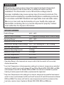
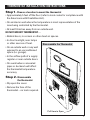
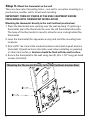
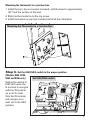
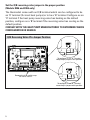
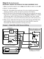
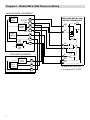
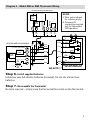
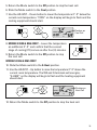
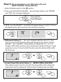
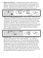
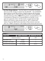
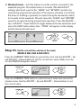
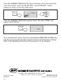
Electronic
Thermostats
MODEL 8344 HEAT/COOL NON-PROGRAMMABLE
MODEL 8346 HEAT PUMP NON-PROGRAMMABLE
MODEL 8348 HEAT/COOL MULTI-STAGE NON-PROGRAMMABLE
MODEL 8363 HEAT/COOL 5/2 DAY PROGRAMMABLE
MODEL 8365 HEAT PUMP 5/2 DAY PROGRAMMABLE
MODEL 8366 HEAT/COOL MULTI-STAGE 5/2 DAY PROGRAMMABLE
Installation Manual
WARNINGS
120 volts may cause serious injury from electrical shock. Disconnect
electrical power to the furnace & air conditioner before starting
installation. This thermostat is not a 120 volt (line voltage) device.
Improper installation may cause serious injury from electrical shock. This
product must be installed by a qualified heating & air conditioning contractor
in accordance with NEC Standards and applicable local and state codes.
Mercury is toxic and may be hazardous to your health. Any replaced
thermostats containing mercury must be disposed of properly. Contact
local authorities for disposal information.
SPECIFICATIONS
Comfort Range
60°F – 80°F
Comfort Control Accuracy
± 1°F (applies to settings within Comfort Range)
Operating Range1
32°F – 99°F
Maximum Control Accuracy
± 2°F
Temperature Setting (Control) Range 50°F – 90°F heating; 60°F – 90°F cooling
Switched Load Voltage
18 – 30 volts
Maximum Operating Current
1.0 Amp
Maximum Surge Current
3.0 Amps
Low Limit Temperature2
41°F ± 9°F
High Limit Temperature3
100°F ± 9°F
1
Operating Range is the temperature range in which the thermostat will accurately
display temperature.
2
Low Limit Temperature is the temperature setting of an internal, temperature-controlled
mechanical switch in a circuit between RH and W for Models 8344, 8348, 8363 and 8366,
and between R and W2 for Models 8346 and 8365. This device is intended to prevent
freezing of water pipes should battery replacement be neglected.
3
High Limit Temperature is the setting of an internal, temperature-controlled mechanical
switch in the circuit between the RH and the W terminal (W and W2 terminals for Model
8348 and 8366). This device will limit the room temperature should the contacts of the
heat relay remain closed. Applies to Models 8344, 8348, 8363 and 8366 only.
1
THERMOSTAT INSTALLATION INSTRUCTIONS
Step1. Choose a location to mount the thermostat
• Approximately 5 feet off the floor (refer to local codes for compliance with
the Americans with Disabilities Act).
• On an interior wall where the temperature is most representative of the
zone being controlled by the thermostat.
• At least 18 inches away from an outside wall.
DO NOT MOUNT THERMOSTAT…
• Behind doors, in corners or other dead air spaces.
• In direct sunlight, near lamps
or other sources of heat.
Disassemble the Thermostat
• On an outside wall or any wall
exposed to an unconditioned
space (i.e. garage).
• In the airflow path of a supply
register or near outside doors.
• On a wall where concealed
pipes or ductwork will affect
the thermostat temperature
accuracy.
Step 2. Disassemble
the thermostat
• Flip open the cover.
• Remove the face of the
thermostat – no tools required.
Pull Here to Open
2
Step 3. Mount the thermostat on the wall
There are two sets of mounting holes – one set for use when mounting to a
junction box, another set for direct wall mounting.
IMPORTANT! TURN OFF POWER AT THE HVAC EQUIPMENT BEFORE
PROCEEDING WITH THERMOSTAT INSTALLATION!
Mounting the thermostat directly to the wall (without junction box)
1. Place the thermostat wire opening over the wall opening. If replacing a
thermostat, place the thermostat to cover the old thermostat silhouette.
The base of the thermostat is raised to allow for wire routing behind the
thermostat.
2. Level the thermostat (for appearance only) and mark the mounting hole
locations.
3. Drill a 3/16” dia. hole at the marked locations and install drywall anchors
(included). Drywall anchors should be used unless installing on paneling
or other hard surfaces. Anchors should be flush with the wall surface.
4. Secure the thermostat to the wall using two (2), #8 x 1-1/2” long pan head
screws (included).
Mounting the Thermostat Directly to the Wall (without Junction Box)
3
Mounting the thermostat to a junction box
1. Install the top j-box screw (not included), until the head is approximately
1/8” from the surface of the wall.
2. Slide the thermostat on to the top screw.
3. Install the bottom screw (not included) to finish the installation.
Mounting the Thermostat to a Junction Box
Step 4. Set the ELEC/GAS switch to the proper position
(Models 8344, 8348,
8363 and 8366 only)
Setting the switch to
ELEC will cause the
G terminal to energize
with the W terminal
on a call for heat.
Only the W terminal
will energize on a
heat call in the GAS
position.
Set ELEC/GAS switch
ELEC
GAS
4
Set the O/B reversing valve jumper in the proper position
(Models 8346 and 8365 only)
The thermostat comes with an O/B terminal which can be configured to be
an ‘O’ terminal (for most heat pumps) or to be a ‘B’ terminal. Configure as an
‘O’ terminal if the heat pump reversing valve has heating as the default
position, configure as a ‘B’ terminal if the reversing valve has cooling as the
default position.
CONSULT WITH THE HEAT PUMP MANUFACTURER TO DETERMINE WHICH
CONFIGURATION IS NEEDED.
O/B Reversing Valve Pin Jumper Position
To configure as an “O” Terminal,
keep the pin jumper in this position.
Remove the slide switch caps
for easier access.
To configure as an “B” Terminal,
move the pin jumper to this position.
5
Step 5. Wire the thermostat
IMPORTANT! ENSURE THE POWER AT THE HVAC EQUIPMENT IS OFF.
1. Make sure the fan switch is set to Auto and the Mode switch is set to Off.
2. Strip 2” of cable insulation.
3. Strip 1/4” of insulation from each wire. Do not cut into the wire when
stripping insulation, as this can lead to eventual control failure.
4. Secure the wires to the thermostat terminal strip according to the wiring
diagram for the model being installed (See Diagrams 1, 2 & 3). Use a slotted
screw driver with a 1/8” tip (terminal screw driver). Use color coding
where possible (i.e. red wire to R terminal, white wire to W terminal, etc.).
5. Slide excess cable back into the wire entry wall opening and fill the hole
with insulation. Failure to seal the hole can cause drafts to enter the
thermostat and effect temperature sensing accuracy.
Diagram 1 – Model 8344 or 8363 Thermostat Wiring
FURNACE
1ST
STAGE
HEAT
1ST STAGE COOL
FAN
RELAY
APRILAIRE MODEL 8344
OR 8363 THERMOSTAT
W1
W
HI
G
GAS
C
24
VAC
120
VAC
ELEC
R
Y
L1
L2
LO
Y1
G
AUTO
ON
RC
COOLING EQUIPMENT
RH
1ST
STG
COOL
Y1
C
HI opens at 100°F±9°F
LO closes at 41°F±9°F
6
Diagram 2 – Model 8348 or 8366 Thermostat Wiring
HEAT/BLOWER EQUIPMENT
2ND
STAGE
HEAT
W2
2ND STAGE
COOL
1ST
STAGE
HEAT
1ST STAGE
COOL
FAN
RELAY
APRILAIRE MODEL 8348
OR 8366 THERMOSTAT
Y2
W2
LO
W1
Y1
HI
W
G
GAS
C
120
VAC
R
Y2
L1
L2
24
VAC
ELEC
Y
COOLING EQUIPMENT
1ST
STG
COOL
2ND
STG
COOL
Y2
RC
AUTO
ON
RH
Y1
C
7
G
HI opens at 100°F±9°F
LO closes at 41°F±9°F
Diagram 3 – Model 8346 or 8365 Thermostat Wiring
OUTDOOR HEAT PUMP UNIT
NOTES:
1. Wire colors shown
for reference only.
2. Common (C)
connection required
only for thermostat
LED operation.
W2
C
L
R
WHT
BLK
BLU
RED
SERVICE
Y1
O/B
YLW
ORG
REV
VALVE
DEFROST
1ST
STG
COMP.
AUX
WHT
W2
YLW
Y
Y1
ORG
YLW
W2
WHT
GRN
G
G
GRN
HEAT/BLOWER EQUIPMENT
1ST STAGE COMPRESSOR
AUX.
HEAT
YLW
ORG
BLU
L
RED
BLK
WHT
BLU
LO
BLU
AUTO
ON
FAN
RELAY
ORG
C
24
VAC
120
VAC
RED
HEAT
COOL
RED
R
O/B
BLK
BLK
L1
L2
CHECK
SEE NOTE 2
R
C
APRILAIRE MODEL 8346
OR 8365 THERMOSTAT
Step 6. Install supplied batteries
Install two new AA alkaline batteries (included). Do not mix old and new
batteries
Step 7. Reassemble the thermostat
No tools required – simply snap the thermostat face back on the thermostat.
8
Step 8. Perform check-out
CAUTION
The following procedure will turn on the heating and cooling equipment.
Do not attempt to turn on the cooling equipment when the outdoor
temperature is too low or the heat pump (heating) when the outdoor
temperature is too high as compressor damage could occur. Consult the
equipment manufacturer literature for safe operating temperatures.
1. Slide the Fan switch to the On position.
The blower should come on. Return the Fan switch
to the Auto position.
FAN
Auto • On
2. Slide the Mode switch to the Heat position.
3. Use the ADJUST – Up button to raise the
temperature 2° - 3° above the current room temperature. “HEAT” on the
display will begin to flash and the heating equipment should start. It may
take a moment for the heating equipment to initiate the heating cycle. If
the blower turns on immediately and this is unexpected, make sure the
GAS/ELEC switch on the thermostat is set correctly (see Step 4, MODELS
8344, 8348, 8363 & 8366 ONLY).
MODELS 8346 & 8365 – If cold air is coming out of the registers, the
reversing valve terminal may need to be configured – see Step 4.
MODE
F
OVERRIDE
ROOM
AM
Cool • Off • Heat
ADJUST
SET
Flashes on
Heat Call
HEAT
SU
4. MODELS 8348 & 8366 ONLY – Raise the temperature an additional 2°-3°
and confirm that the second stage of heat (W2) comes on after a 2 minute
1st stage minimum on-time.
MODELS 8346 & 8365 ONLY – Raise the temperature an additional 2°-3° and
confirm that the second stage of heat (W2) comes on in four (4) minutes.
The green AUX LED located on top of the thermostat will light whenever
the W2 terminal is energized.
9
5. Return the Mode switch to the Off position to stop the heat call.
6. Slide the Mode switch to the Cool position.
7. Use the ADJUST – Down button to lower the temperature 2°- 3° below the
current room temperature. “COOL” on the display will begin to flash and the
cooling equipment should start.
MODE
F
OVERRIDE
Cool • Off • Heat
ROOM
SET
AM
ADJUST
Flashes on
Cool Call
COOL
SU
8. MODELS 8348 & 8366 ONLY – Lower the temperature
an additional 2°- 3° and confirm that the second
stage of cooling (Y2) comes on after four (4) minutes.
MODE
Cool • Off • Heat
9. Return the Mode switch to the Off position to stop
the cool call.
MODELS 8346 & 8365 ONLY
10. Slide the Mode switch to the E-Heat position.
11. Use the ADJUST – Up button to raise the temperature 2°-3° above the
current room temperature. The W2 and G terminals will energize,
“E-HEAT” on the display will begin to flash and the heating equipment
should start.
MODE
F
OVERRIDE
ROOM
AM
Cool • Off • Heat • E-Heat
ADJUST
SET
Flashes on
Heat Call
E-HEAT
SU
12. Return the Mode switch to the Off position to stop the heat call.
10
Step 9. Set up temperature scale, differential, offset and
Water Panel/filter change indicators
1. Slide the Mode switch to the Off position.
2. Press and hold both the ADJUST – Up and Down buttons until “ROOM”
and “OFF” are no longer displayed.
Press and Hold
Simultaneously for
Three (3) Seconds
ADJUST
3. °F/°C – Use the ADJUST – Up button to toggle between °F and °C. Press
the LIGHT button when desired scale has been selected.
F
C
LIGHT
ADJUST
4. Differential Setting (d1) – The unit is shipped with this set to 1(°). This
refers to how much the temperature will swing during control. Use the
ADJUST – Up or ADJUST – Down button to change this to 1°, 2° or 3°.
A higher differential will allow more temperature swing and fewer, longer
equipment cycles. Press the LIGHT button when the desired differential
has been set.
OR
LIGHT
ADJUST
ADJUST
5. Second Stage Differential Setting (d2 – MODELS 8348 & 8366 ONLY) –
This setting controls how far from the first stage differential setting the
temperature will be allowed to fall/rise before initiating second stage.
OR
LIGHT
ADJUST
11
ADJUST
6. Temperature Offset (OF) – All thermostats are factory calibrated to be
within 1° of true temperature. Offset is available to allow for agreement
with field temperature measuring instruments. Use the ADJUST – Up or
ADJUST – Down button to change the offset value between –4° and +4°.
Press the LIGHT button when the desired offset value has been set.
OR
LIGHT
ADJUST
ADJUST
7. Water Panel Change Indicator Feature – Use this feature if the home has
a whole house humidifier such as an Aprilaire Humidifier. This feature will
remind the homeowner when it is time to change the Water Panel. Use
the ADJUST – Up or ADJUST – Down button to set the number of months
until the first indication. The first indication should occur in fall (near
October). The indicator will then show again every 52 weeks to remind the
homeowner to change the Water Panel in their humidifier. Set the value to
“OFF” to disable this feature. Press the LIGHT button when the Water
Panel indicator value has been set.
CHANGE
WATER PANEL
CHANGE
WATER PANEL
LIGHT
ADJUST
8. Humidifier Type – This feature will only be displayed if the Water Panel
Change value is not set to “OFF”. Use the ADJUST – Up or ADJUST –
Down button to set this value to “1” if the home has an Aprilaire Model
400 whole house humidifier. The Water Panel in the Model 400 should be
changed twice per season and this feature will cause the Water Panel
Change Alert to appear on the display 90 days after the first alert. For
example, if the Water Panel Change Alert value is set to show the first
alert in October, then a second alert will appear in January. An alert will
not be displayed again until the next October, and the cycle repeats. Press
the LIGHT button when the humidifier type value has been set.
12
WATER PANEL
WATER PANEL
LIGHT
ADJUST
9. Air Filter Change Indicator – Use this feature to remind the homeowner
when an air filter change is needed. Use the ADJUST – Up and ADJUST –
Down buttons to select the number of months between recommended
filter changes. Use 1 or 3 for panel type filters and 6 or 12 for extended
(pleated) media type filters. TABLE 1 lists general recommendations, refer
to manufacturer literature for recommendations on the filter in your
particular application. Set to 12 if the media is original Aprilaire High
Efficiency Air Cleaner media. Set the value to “OFF” to disable this
feature. Press the LIGHT button when the air filter indicator value has
been set. “DONE” will appear on the display and the thermostat will reset.
CHANGE FILTER
CHANGE FILTER
LIGHT
ADJUST
TABLE 1
FILTER TYPE
CHANGE FREQUENCY
Disable the feature
THERMOSTAT SETTING
OFF
Disposable Panel
1 month
1
Washable Electrostatic
3 months
3
6-12 months
6 or 12
Extended Media (Aprilaire)
13
10. Weekend Events – Use this feature to set the number of events for the
weekend program. The default value is 4 events (The ENERGYSTAR®
setting), which will result in the “LEAVE” and “RETURN” events to be
used during programmed operation. If the owners schedule is such that
the home or building is generally occupied during the weekends, switch
to 2 events on the weekend. This will cause the “LEAVE” and “RETURN”
events to be ignored during programmed operation. Press the ADJUST –
Up or ADJUST – Down buttons to toggle between the two selections and
press the LIGHT button when done. “DONE” will appear on the display
and the thermostat will reset.
WAKE
WAKE
LEAVE
RETURN
SLEEP
SLEEP
LIGHT
SA SU
ADJUST
SA SU
Step 10. Set the current time and day of the week
(MODELS 8363, 8365 & 8366 ONLY)
Press the CURRENT TIME button to access the clock. Use the ADJUST – Up
and ADJUST – Down buttons to set the correct hour value. Make sure the
correct AM/PM designator shows.
CURRENT TIME
Make sure
AM/PM
is correct
AM
[Advance Time]
ADJUST
MO
Press the CURRENT TIME button to enter the hours value and access the
minutes value. Use the ADJUST – Up and ADJUST – Down buttons to set
the correct value.
CURRENT TIME
Adjust Minutes
AM
[Advance Time]
MO
ADJUST
14
Press the CURRENT TIME button to enter the minutes value and access the
“day of the week” value. Use the ADJUST – Up and ADJUST – Down
buttons to set the current day of the week.
CURRENT TIME
Adjust Day of
the Week
AM
[Advance Time]
ADJUST
MO
Press the CURRENT TIME button again to finish. The word “DONE” will
appear on the display.
CURRENT TIME
DONE
[Advance Time]
As an ENERGYSTAR® partner, the thermostat (Models 8363, 8365 and 8366 only)
has been pre-programmed with economical times and temperature settings.
Refer to the Operating Instructions if the program is to be changed.
P.O. BOX 1467 • MADISON, WI 53701-1467
Products For Better Indoor Air Quality™
Form No. 5172 09.04
B2202977A
15
MADE IN USA
© 2004 Research Products Corporation