1
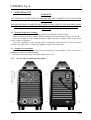
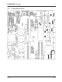
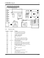
CEBORA S.p.A. 1 POWER TIG 1540 DC-HF POWER SOURCE art. 271 SERVICE MANUAL 3.302.212 12/01/06 CEBORA S.p.A. 2 CONTENTS 1 - GENERAL INFORMATION...........................................................................................................3 1.1 - Introduction. ...................................................................................................................................3 1.2 - General service policy....................................................................................................................3 1.3 - Safety information..........................................................................................................................3 1.4 - Electromagnetic compatibility. ......................................................................................................3 2 - SYSTEM DESCRIPTION................................................................................................................4 2.1 - Introduction. ...................................................................................................................................4 2.2 - Technical specifications. ................................................................................................................4 2.3 - Description of power source art. 271. ............................................................................................4 3 - MAINTENANCE .............................................................................................................................5 3.1 - Periodic inspection, cleaning. ........................................................................................................5 3.2 - Sequence of operations. .................................................................................................................5 3.2.1 - Power source commands and signals. .........................................................................................5 3.2.2 - Starting the power source. ...........................................................................................................6 3.2.3 - TIG operation. .............................................................................................................................6 3.2.4 - MMA operation. ..........................................................................................................................7 3.3 - Troubleshooting. ............................................................................................................................8 3.3.1 - The power source does not start, control panel off......................................................................8 3.3.2 - Power source powered, fan (16) stopped.....................................................................................9 3.3.3 - Power source powered, display and signals does not indicate the correct values. ......................9 3.3.4 - In TIG, the start button produces no effect................................................................................11 3.3.5 - In TIG, no gas flows from the torch. .........................................................................................11 3.3.6 - In TIG, gas flows from the torch, the arc does not start, high frequency missing.....................12 3.3.7 - In open circuit operation, the output voltage is not regular. ......................................................13 3.3.8 - In resistive load operation, the output voltage is not regular.....................................................14 3.3.9 - In TIG, arc unstable, welding irregular. ....................................................................................15 3.4 - Error codes. ..................................................................................................................................15 3.4.1 - Yellow led (G) lit = temperature above limits...........................................................................15 3.4.2 - Yellow led (G) lit at the power source start-up = supply voltage above limits. ........................15 3.4.3 - Yellow led (G) lit + led (F) flashing = “Vs” voltage above limit..............................................15 3.4.4 - Yellow led (G) lit + led (E) flashing = “Vs” voltage under limit. .............................................15 4 - COMPONENTS LIST....................................................................................................................16 4.1 - Power source art. 271: see file ESP271.pdf enclosed at the end of the manual. ..........................16 4.2 - Components table: see file ESP271.pdf enclosed at the end of the manual.................................16 4.3 - Spare parts list. .............................................................................................................................16 5 - ELECTRICAL DIAGRAMS..........................................................................................................16 5.1 - Power source art. 271: see file SCHE271.pdf enclosed at the end of the manual........................16 5.2 - Power board (29) code 5.602.182/D. ...........................................................................................16 5.3 - Panel board (26) code 5.602.183..................................................................................................18 3.302.212 12/01/06 CEBORA S.p.A. 3 1 - GENERAL INFORMATION 1.1 - Introduction. The purpose of this manual is to train personnel assigned to carry out maintenance on the power source art. 271 for TIG and MMA welding systems. 1.2 - General service policy. It is the responsibility of the customer and/or operator to use the equipment appropriately, in accordance with the instructions in the Instruction Manual, as well as to maintain the equipment and related accessories in good working condition, in compliance with the instructions provided in the Service Manual. Any internal inspection or repairs must be carried out by qualified personnel who are responsible for any intervention on the equipment. It is forbidden to attempt to repair damaged electronic boards or modules; replace them with original Cebora spare parts. 1.3 - Safety information. The safety notes provided in this manual are an integral part of those given in the Instruction Manual. Therefore, before working on the machine, please read the paragraph on safety instructions in the aforementioned manual. Always disconnect the power cord from the mains, and wait for the internal capacitors to discharge (2 minutes) before accessing the interior of the equipment. Some internal parts, such as terminals and dissipaters, may be connected to mains or otherwise hazardous potentials. It is therefore forbidden to work with the safety guards removed from the machine unless strictly necessary. In this case, take special precautions such as wearing insulating gloves and footwear, and working in a perfectly dry environment with dry clothing. 1.4 - Electromagnetic compatibility. Please read and observe the instructions provided in the paragraph “Electromagnetic compatibility” of the Instruction Manual. 3.302.212 12/01/06 CEBORA S.p.A. 4 2 - SYSTEM DESCRIPTION 2.1 - Introduction. The POWER TIG 1540 DC-HF is a system for MMA and TIG welding, with arc starting in both contact and high frequency mode. It is made up of an electronic power source (art. 271), and a set of accessories to adapt to various applications (see list in Sales Catalogue). The power source is controlled by a microprocessor circuit, which manages the operative functions of the welding system and operator interface. 2.2 - Technical specifications. To verify the technical specifications, see the machine plate, Instruction Manual, and Sales Catalogue. 2.3 - Description of power source art. 271. Art. 271 is a voltage power source with controlled current, consisting of a single-phase rectifier bridge and a DC/DC mosfet converter. Referring to the electrical diagram in par. 5.1, drawing 4.1 and table 4.2, we can identify the main blocks that make up the power source. The main switch (6) powers the power board (29), which constitutes practically alone, the complete power source. It contains both the power circuit and the control circuits to manage the functions of the power source art. 271. The welding current is regulated by the microprocessor of the power board (29), based on the signals received from the connector (I), on the panel board (26), and the parameters set via the panel board (26). The microprocessor manages the gas solenoid valve (11) in applications that require it, and controls the condition of the supply voltage, to activate any safety devices necessary to protect the power source (see Error codes par. 3.4). The panel board (26) contains the leds for signaling, the buttons and potentiometer for setting and programming the operating parameters. The panel board (26) is fully controlled by the microprocessor of the power board (29), from which it also receives power. Includes the connector (I) to connect the external control devices to the power source, such as the TIG torch start button, the potentiometer for external adjustment of the welding current, and the UP/DOWN buttons for digital current adjustment. These signals are appropriately filtered by the components present on the panel board (26), against conducted interference from the welding field. Included in the power board (29) is the HF generator circuit, that together with the HF transformer (27), allows to start the welding arc without contact between the electrode and the workpiece. It is managed directly by microprocessor through relè RL3, based on panel board (26) parameter set-up. In TIG operation with HF, the start signal commands closing of relè RL3, and the power transformer secondary voltage is applied to the HF generator composed by the following devices: RS1, RS2, RS3, CS1, CS2, L3, TF4, SC1, CS3, CS4, CS5, CS6 and CS7. Near the output terminals (POS) and (NEG) of the power board (29), are three capacitors (C50, C51 and C67) which serves to prevent the high voltage and high frequency pulses generated by the HF transformer (27) travel along the circuits into the power board (29), where they would cause malfunctions or errors. In addition, they play a decisive role in the efficiency of starting the pilot arc with the high frequency. The signals processed by the electronic boards and present at their connectors are listed in the tables in chapter five of this manual. 3.302.212 12/01/06 CEBORA S.p.A. 5 3 - MAINTENANCE WARNINGS ANY INTERNAL INSPECTIONS OR REPAIRS MUST BE CARRIED OUT BY QUALIFIED PERSONNEL. BEFORE BEGINNING MAINTENANCE OPERATIONS, UNPLUG THE MACHINE FROM THE MAINS AND WAIT FOR THE INTERNAL CAPACITORS TO DISCHARGE (2 MINUTES). 3.1 - Periodic inspection, cleaning. Periodically make sure that air is flowing properly within the aeration tunnel. Remove any dirt or dust to ensure adequate cooling of the internal parts of the power source. Check the condition of the output terminals, output and power supply cables of the power source; replace if damaged. Check the condition of the internal power connections and connectors on the electronic boards; if you find “loose” connections, tighten or replace the connectors. 3.2 - Sequence of operations. The following sequence represents correct functioning of the machine. It may be used as a guiding procedure for troubleshooting. It must be carried out after each repair without any errors. 3.2.1 3.302.212 - Power source commands and signals. 12/01/06 CEBORA S.p.A. 6 NOTE Operations preceded by this symbol refer to operator actions. ♦ Operations preceded by this symbol refer to machine responses that must occur following an operator action. 3.2.2 - Starting the power source. System shut off and disconnected from the mains. Connect the power source to the mains. Close the switch (6). ♦ System powered, lamp on the switch (6) lit, fan (16) working, yellow led (G) lit. ♦ After three seconds, all of the leds on panel board (26) lit (lamp-test). ♦ After one second, only one green led remains lit according to the “Process” and “Mode” setting before the unit was last shut off. Correct? NO (see 3.3.1, 3.3.2, 3.3.3). YES Press the button (A) several times; the “Process” and “Mode” selection is repeated in sequence. ♦ Each time the button (A) is pressed, the leds F, E, D, C and B light one after another. Correct? NO (see 3.3.3). YES 3.2.3 - TIG operation. WARNINGS DURING THE FOLLOWING TESTS DO NOT AIM THE TORCH AT PEOPLE OR PARTS OF THE BODY, BUT ONLY TOWARDS AN OPEN SPACE OR THE WORKPIECE. DO NOT TRY TO MEASURE THE OUTPUT VOLTAGE DURING THESE STEPS. THE PRESENCE OF HIGH FREQUENCY MAY DAMAGE THE INSTRUMENT OR THE POWER SOURCE ITSELF. Switch-off the power source through switch (6). Connect the gas supply to the fitting (R) provided on the rear panel. Connect the TIG torch to the negative pole (P) of the power source, to the fitting gas (O) and to commands connector (I), on front panel. Connect the cable of the positive pole (Q) of the power source to the workpiece. Switch-on the power source, closing the switch (6). After the lamp-test, use the button (A) to select the TIG-2TIMES with HF “Process” and “Mode”, led C lit. Briefly press the torch start button. ♦ The pre-gas phase begins with gas flowing from the torch, for as long as the button is held down. ♦ Gas continues to flow from the torch for the duration of the post-gas time set, adjustable with knob (L), after the start button is released. Correct? NO (see 3.3.4, 3.3.5). YES 3.302.212 12/01/06 CEBORA S.p.A. 7 Press the start button and hold it down for approximately 5 seconds. ♦ The pre-gas phase begins; the high frequency is then generated to start the arc, as well as the power source output voltage. ♦ After approximately two seconds, the output voltage and high frequency to start the arc are no longer generated, and the post-gas phase begins (TIG operation with HF stops if there is no current at the power source output after start-up). Correct? YES Move the torch near the workpiece and press the torch trigger. ♦ Begin welding. Turn the knob (H) or the torch potentiometer to obtain the current level suitable for the type of welding to be done. Correct? NO (see 3.3.6, 3.3.7). NO (see 3.3.8, 3.3.9). YES Release the torch start button. ♦ The arc shuts off immediately (if long ramp times are not set (slope down)). Gas continues to flow for the post-gas time. Correct? NO (see 3.3.5). YES REGULAR OPERATION. 3.2.4 - MMA operation. Switch-off the power source through switch (6). Connect the electrode clamp to the positive pole (Q) of the power source. Connect the cable of the negative pole (P) of the power source to the workpiece. Switch-on the power source, closing the switch (6). After the lamp-test, use the button (A) to select the MMA “Process”, led (F) lit. ♦ Voltage begins to be generated at the power source output. Correct? NO (see 3.3.7). YES Use the knob (H) or the remote unit potentiometer to set the current based on the electrode you intend to use. Move the electrode clip near the workpiece. ♦ Begin welding. Adjust the knob (H) or the remote unit potentiometer to maximize the welding quality. Correct? NO (see 3.3.8). YES REGULAR OPERATION. 3.302.212 12/01/06 CEBORA S.p.A. 8 3.3 - Troubleshooting. WARNINGS ANY INTERNAL INSPECTIONS OR REPAIRS MUST BE CARRIED OUT BY QUALIFIED PERSONNEL. BEFORE REMOVING THE PROTECTIVE GUARDS AND ACCESSING INTERNAL PARTS, DISCONNECT THE POWER SOURCE FROM THE MAINS AND WAIT FOR THE INTERNAL CAPACITORS TO DISCHARGE (2 MINUTES). NOTE Items in boldface describe problems that may occur on the machine (symptoms). Operations preceded by this symbol refer to situations the operator must determine (causes). ♦ Operations preceded by this symbol refer to actions the operator must perform in order to solve the problems (solutions). 3.3.1 - The power source does not start, control panel off. MAINS SUITABILITY TEST. No voltage for mains protection. NO ♦ ♦ ♦ ♦ Correct? YES Eliminate any short-circuits on the connections between power cable, switch (6), power board (29) and fan (16). Make sure that the terminals X220 and VAC1 on power board (29) are not shortcircuited between them or towards earth. Make sure that terminals of the fan (16) are not short-circuited between them or towards earth. Mains not suitable to power the power source (ex.: insufficient installed power). MAINS CONNECTION TEST. Terminals X220 and VAC1 on power board (29) = 230 Vac, with switch (6) closed. YES Correct? NO ♦ Check power cable and plug and replace if necessary. ♦ Check switch (6), and replace if defective. ♦ Check the mains voltage conditions. PANEL BOARD (26) POWER SUPPLY TEST. Panel board (26), connector CN2, terminals 1(+) and 2(-) = +5 Vdc. YES Correct? NO 3.302.212 12/01/06 CEBORA S.p.A. 9 ♦ Check the wiring between CN2 power board (29) and CN2 panel board (26). ♦ Disconnect temporarily, with power source off, connector CN2 on panel board (26) and verify terminals 1 and 2 of CN2 on panel board (26) are not in short circuit. If the case, replace panel board (26), and verify, powering the power source with connector CN2 disconnected, the presence of 5 Vdc on terminals 1 and 2 of connector CN2 remained free. If lacking replace also power board (29). ♦ Replace panel (26) and or power (29) boards. 3.3.2 - Power source powered, fan (16) stopped. FAN (16) TEST. Fast-on terminals fan (16) = 230 Vac approximately, with switch (6) closed. NO Correct? YES ♦ Make sure that there are no mechanical impediments blocking the fan. ♦ Replace the fan (16). ♦ Check the wiring between the fan (16) and switch (6). ♦ Check the mains voltage conditions. ♦ Replace the switch (6). 3.3.3 - Power source powered, display and signals does not indicate the correct values. LAMP-TEST. Panel board (26), all leds lit for 1 second, after the switch (6) is closed. YES Correct? NO ♦ Check the wiring between the CN2 power board (29) and CN2 panel board (26). ♦ Check the power source supply, par. 3.3.1. ♦ Replace panel (26) and/or power (29) boards. ERROR CODE TEST. Upon start-up, after the lamp-test, yellow led (G) = lit. NO Correct? YES ♦ See par. 3.4, Error code. ♦ Check the power source supply, par. 3.3.1. ♦ Replace panel (26) and/or power (29) boards. 3.302.212 12/01/06 CEBORA S.p.A. 10 SIGNALING TEST. Upon start-up, after the lamp-test, pressing button (A) several times the “Process” and “Mode” selection is repeated in sequence, indicated by leds F, E, D, C and B that lit in sequence. YES Correct? NO ♦ Check the wiring between the CN2 power board (29) and CN2 panel board (26). ♦ Replace panel (26) and/or power (29) boards. POTENTIOMETER ADJUSTING TEST. Power board (29), connector CN2, terminals 10(+) and 2(-) = 0 – +5 Vdc, turning the potentiometer H (current) on panel board (26). Power board (29), connector CN2, terminals 11(+) and 2(-) = 0 – +5 Vdc, turning the potentiometer M (slope) on panel board (26). Power board (29), connector CN2, terminals 12(+) and 2(-) = 0 – +5 Vdc, turning the potentiometer L (post-gas) on panel board (26). YES Correct? NO ♦ Check the wiring between the CN2 power board (29) and CN2 panel board (26). ♦ Make sure voltage +5 Vdc on terminals 1(+) and 2(-) of CN2 on panel board (26) (potentiometer power supply). If missing, make sure the same voltage on terminals 1(+) and 2(-) of CN2 on power board (29), check the wiring between the two connectors or replace power board (29). ♦ Replace panel (26) and/or power (29) boards. EXTERNAL CURRENT SETTING TEST (torch potentiometer or push button). Power board (29), connector CN1, terminals 2(+) and 3(-) = 0 – +5 Vdc, turning the potentiometer on the torch. Power board (29), connector CN1, terminals 6(+) and 8(-) = 0 Vdc (UP command), with UP button pressed (+5 Vdc with button released). Power board (29), connector CN1, terminals 5(+) and 8(-) = 0 Vdc (DOWN command), with DOWN button pressed (+5 Vdc with button released). YES Correct? NO ♦ Check the wiring between CN1 power board (29) and CN1 panel board (26). ♦ Make sure the torch connector in correctly inserted in connector (I). ♦ Check potentiometer on the torch. If defective, replace. ♦ Check UP/DOWN buttons. If defective, replace. ♦ Replace panel (26) and/or power (29) boards. ♦ Regular operation. If that in spite some function during the welding it is not corrected replace power board (29). 3.302.212 12/01/06 CEBORA S.p.A. 3.3.4 11 - In TIG, the start button produces no effect. START COMMAND TEST. Power board (29), connector CN1, terminals 4(+) and 8(-) = 0 Vdc (start), with torch button pressed (+5 Vdc with button released). YES Correct? NO ♦ Check the wiring between CN1 power board (29) and CN1 panel board (26). ♦ Make sure the torch connector in correctly inserted in connector (I). ♦ Check cable and start button on the torch. If defective, replace. ♦ Replace panel (26) and/or power (29) boards. ♦ Replace the power board (29). 3.3.5 - In TIG, no gas flows from the torch. SOLENOID VALVE TEST. Solenoid valve (11) terminals = 230 Vac with torch button pressed (the duration of the solenoid valve opening also depends on the post-gas parameters set). NO ♦ ♦ ♦ ♦ Correct? YES ♦ Check the presence of gas at the power supply fitting (R) provided on the rear panel, and make sure that the pressure and air flow, in the intake line, comply with the specified values (see specifications in the Instruction Manual). ♦ Make sure there are no occlusions in the gas hoses of the power source. ♦ Make sure, with power source off and disconnected from the mains, the resistance on solenoid valve (11) terminals = 2500 ohm. If >Mohm (winding broken) replace solenoid valve (11). ♦ Replace solenoid valve (11). Check wiring between terminals EV1 and EV2 of power board (29) and solenoid valve (11). Make sure start command operation, performing the START COMMAND TEST par. 3.3.4 if necessary. Make sure, with power source off and disconnected from the mains, the resistance on solenoid valve (11) terminals = 2500 ohm. If 0 ohm (short-circuit), replace solenoid valve (11) and check efficiency of the relè RL2 on power board (29), and replace it if necessary. Replace power board (29). 3.302.212 12/01/06 CEBORA S.p.A. 12 3.3.6 - In TIG, gas flows from the torch, the arc does not start, high frequency missing. WARNING DURING THE FOLLOWING TESTS LEAVE FREE FROM CONNECTIONS AND DO NOT TOUCH THE OUTPUT TERMINAL NEGATIVE (P) OF THE POWER SOURCE. THE EVENTUAL PRESENCE OF HIGH VOLTAGE AND HIGH FREQUENCY IS DANGEROUS FOR OPERATOR AND CAN DAMAGE THE INSTRUMENTS OR THE POWER SOURCE. SECONDARY RECTIFIER OUTPUT VOLTAGE TEST. Set the TIG without high frequency operation (led E lit). Power source positive output terminal (Q)(+), and “NEG” terminal on power board (29)(-) = +98 Vdc approximately, with start button pressed (output voltage of the secondary rectifier output, upstream the HF transformer (27)). YES Correct? NO ♦ Make sure start command operation (see par. 3.3.4). ♦ Check the mains voltage conditions and perform test of par. 3.3.1 if necessary. ♦ Replace power board (29). HF OSCILLATOR TEST. Set the TIG with high frequency operation (led C lit). Power board (29), SC1 discharger discharges at regular intervals, with start button pressed. NO Correct? YES ♦ Make sure that there is no short-circuit between terminals HT and HT on power board (29) or in the wiring of the HF transformer (27) primary circuit. ♦ Check the connections of the secondary circuit of HF transformer (27), “NEG” terminal of the power board (29) and “-” output terminal of the power source. If you find loose connections, tighten and replace any damaged components. ♦ Check connections and integrity of the three capacitors (C50, C51 and C67) which serve to prevent the high voltage and high frequency pulses generated by the HF transformer (27), travel along the circuits into the power board (29), where they would cause malfunctions or errors. If necessary replace them or restore their connections. ♦ Check cable and torch electrode holder; replace if worn or damaged. ♦ Make sure the torch fitting (Gifas) has no isolation leaks, thus is not crossed by surface high voltage discharges. If necessary, replace with a new one. ♦ Check the distance between the tips of the discharger SC1 (correct = 0.9 mm.). ♦ Replace HF transformer (27). ♦ Replace power board (29). ♦ Make sure integrity and operation of the relè RL3 on power board (29). In TIG with HF operation, the start signal commands closing of relè RL3, and the power transformer secondary voltage is applied to the HF generator circuit composed by the following devices: RS1, RS2, RS3, CS1, CS2, L3, TF4, SC1, CS3, CS4, CS5, CS6 and CS7. Check the conditions of such devices and replace them if necessary. 3.302.212 12/01/06 CEBORA S.p.A. 13 ♦ Make sure the good insulation of the HF generator circuit devices installed on printed circuit board of power board (29), and remove eventual traces of dirt or powder that can create short circuits between the devices. ♦ Check the distance between the tips of the discharger SC1 (correct = 0.9 mm.). ♦ Replace power board (29). 3.3.7 - In open circuit operation, the output voltage is not regular. WARNING FOR THESE TESTS DISCONNECT THE HF TRANSFORMER (27) PRIMARY CIRCUIT TERMINALS FROM “HT” TERMINALS OF POWER BOARD (29), TO AVOID HF GENERATION. OPEN-CIRCUIT OUTPUT VOLTAGE TEST. Output terminal – power source (-) and output terminal + power source (+) = voltages per table: Process Voltage Condition TIG +98 Vdc, approx. Start button pressed MMA +102 Vdc, approx. Power source powered YES Correct? NO ♦ Check the connection between the “NEG” terminal on the power board (29), HF transformer (27) and - output terminal of the power source, and the connection between the “POS” terminal of the power board (29) and + power source output terminal. If you find loose connections, tighten and replace any damaged terminals. ♦ In TIG make sure start command operation (see par. 3.3.4). ♦ Check the mains voltage conditions and perform test of par. 3.3.1 if necessary. ♦ Replace power board (29). ♦ Regular operation. 3.302.212 12/01/06 CEBORA S.p.A. 3.3.8 14 - In resistive load operation, the output voltage is not regular. WARNING FOR THE FOLLOWING TESTS SET OPERATION TIG WITH HIGH FREQUENCY, LED (C) LIT, BUT DISCONNECT THE HF TRANSFORMER (27) PRIMARY CIRCUIT TERMINALS FROM “HT” TERMINALS OF POWER BOARD (29) TO AVOID HF GENERATION. NOTE For the following tests use a resistive load capable of withstanding the maximum power source current. The appropriate values are shown in the table. Process Resistive load Maximum output Power source Condition resistance current output voltage TIG 0.107 ohm 150 Adc +16 Vdc, approx. Start button pressed MMA 0.183 ohm 140 Adc +25.6 Vdc, approx. Power source powered OUTPUT VOLTAGE TEST ON RESISTIVE LOAD. Turn knob (H) maximum clockwise (maximum output current). Output terminal – power source (-) and output terminal + power source (+) = voltage values as in the table, adjustable using the knob (H). YES Correct? NO ♦ Check the connection between the “NEG” terminal on the power board (29), HF transformer (27) and “-” power source output terminal, and the connection between the “POS” terminal of the power board (29) and “+” power source output terminal. If you find loose connections, tighten and replace any damaged terminals. ♦ Check the wiring between CN2 power board (29) and CN2 panel board (26). ♦ Check integrity and operation of potentiometers on panel board (26), performing if necessary the POTENTIOMETER ADJUSTING TEST of par. 3.3.3. ♦ In TIG make sure start command operation (see par. 3.3.4). ♦ Check the mains voltage conditions and perform test of par. 3.3.1 if necessary. ♦ Replace power (29) and/or panel (26) boards. ♦ Regular operation. 3.302.212 12/01/06 CEBORA S.p.A. 3.3.9 15 - In TIG, arc unstable, welding irregular. NOTE In TIG, the welding quality may not be acceptable due to current instability. In this case we recommend switching to MMA operation, and performing welding tests. MMA WELDING QUALITY TEST. Power source in MMA, welding tests = good welding quality. YES Correct? NO ♦ Perform the “open circuit operation” test (par. 3.3.7) and “operation on resistive load” (par. 3.3.8). ♦ Replace the power board (29). ♦ Check the condition of the torch and electrode. If necessary, sharpen the tip of the electrode. ♦ Check the presence and continuity of the gas flow (solenoid valve vibration) at the torch output (see par. 3.3.5). ♦ Replace the power (29) and/or panel (26) boards. 3.4 - Error codes. 3.4.1 - Yellow led (G) lit = temperature above limits. The thermostat is located on the dissipater of the power mosfets of the power board (29). The power source delivers no current, but the fan remains in operation; we therefore recommend leaving the power source powered in case of alarm for overtemperature. Check the temperature of the dissipaters of the power modules on the power board (29), and if necessary wait for them to cool completely. If the alarm persists, replace power board (29). If the alarm is reset, check the efficiency of ventilation, make sure the ambient temperature is not too high, and that the working cycle is not greater than the one specified. 3.4.2 - Yellow led (G) lit at the power source start-up = supply voltage above limits. Alarm for high supply voltage, more than approximately 280 Vac, at start-up. The power source delivers no current, but the fan (16) is supplied at the line voltage and may be damaged in few seconds. To restore proper operation, shut off the power source and restart with the correct voltage. 3.4.3 - Yellow led (G) lit + led (F) flashing = “Vs” voltage above limit. 3.4.4 - Yellow led (G) lit + led (E) flashing = “Vs” voltage under limit. If the supply voltage of the internal driver circuits (Vs) exceeds the allowed limits during operation, this check blocks the power source, with indication of led (F) or (E) flashing. “Vs” voltage is generated by U2 on power board (29), and is measurable between terminal 2 of CN2 (-) and resistor R6 terminal close U6 (+). Rated value = 12.8 Vdc; alarm thresholds: <10 Vdc = led (E) flashing; >16 Vdc = led (F) flashing. Proper operation is restored when voltage returns within allowed limits. If the Vs values are not correct when the mains voltage is within the allowed limits, they can assume power board (29) defective and so to be replaced. 3.302.212 12/01/06 CEBORA S.p.A. 16 4 - COMPONENTS LIST 4.1 - Power source art. 271: see file ESP271.pdf enclosed at the end of the manual. 4.2 - Components table: see file ESP271.pdf enclosed at the end of the manual. 4.3 - Spare parts list. Essential spare parts. Ref. Code 26 5602183 29 5602182 Description panel board power board Qty. 1 1 Recommended spare parts. Ref. Code Description 6 3190014 switch 16 3165075 fan Qty. 1 1 5 - ELECTRICAL DIAGRAMS 5.1 - Power source art. 271: see file SCHE271.pdf enclosed at the end of the manual. 5.2 - Power board (29) code 5.602.182/D. 5.2.1 - Connector table. Connector Terminals CN1 1 CN1 2 CN1 3 CN1 4 CN1 5 CN1 6 CN1 7 CN1 8 CN2 1 CN2 2 CN2 3-4-5-6-7-8 CN2 9 CN2 10 CN2 11 CN2 12 VAC1 – X220 POS – NEG HT – HT 3.302.212 Function “+” output for torch potentiometer. torch potentiometer cursor input. “-“ output for torch potentiometer. “START” signal input. “DOWN” signal input. “UP” signal input. NU. “shared” output for signals from outside. +5 Vdc output for panel board (26) supply. 0 Vdc output for panel board (26) supply. led driving outputs. (A) button signal input. (H) potentiometer signal input (current adjust). (M) potentiometer signal input (slope adjust). (L) potentiometer signal input (post-gas adjust). 230 Vac power supply input. power board (29) power circuit output. HF transformer (27) primary circuit connection terminals. 12/01/06 CEBORA S.p.A. 5.2.2 3.302.212 17 - Topographical drawing. 12/01/06 CEBORA S.p.A. 18 5.3 - Panel board (26) code 5.602.183. 5.3.1 - Topographical drawing. 5.3.2 - Connector table. Connector Terminals CN1 1 CN1 2 CN1 3 CN1 4 CN1 5 CN1 6 CN1 7 CN1 8 CN2 1 CN2 2 CN2 3-4-5-6-7-8 CN2 9 CN2 10 CN2 11 CN2 12 CNP 1 CNP 2 CNP 3 CNP 4 CNP 5 CNP 6 CNP 7 CNP 8 CNP 9 CNP 10 3.302.212 Function “+” input for torch potentiometer. torch potentiometer cursor output. “-“ input for torch potentiometer. “START” signal output. “DOWN” signal output. “UP” signal output. NU. “shared” input for signals from outside. +5 Vdc input for panel board (26) supply. 0 Vdc input for panel board (26) supply. leds driving inputs. (A) button signal output. (H) potentiometer signal output (current adjust). (M) potentiometer signal output (slope adjust). (L) potentiometer signal output (post-gas adjust). “START” signal input. “+” output for torch potentiometer. NU. “DOWN” signal input. NU. NU. “-“ output for torch potentiometer. “UP” signal input. “shared” output for signals from outside. torch potentiometer cursor input. 12/01/06