1
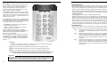
Instruction Manual PC56O © 1997 Digital Security Controls Ltd. 1645 Flint Road, Downsview, Ontario, Canada M3J 2J6 Printed in Canada 29002390 R1 Software Version 1.OA • W A R N I N G • This manual contains information on limitations regarding product use and function and information on the limitations as to liability of the manufacturer. The entire manual should be carefully read. TM Security Products WARNING Please Read Carefully Note to Installers This warning contains vital information. As the only individual in contact with system users, it is your responsibility to bring each item in this warning to the attention of the users of this system. System Failures This system has been carefully designed to be as effective as possible. There are circumstances, however, involving fire, burglary, or other types of emergencies where it may not provide protection. Any alarm system of any type may be compromised deliberately or may fail to operate as expected for a variety of reasons. Some but not all of these reasons may be: n Inadequate Installation A security system must be installed properly in order to provide adequate protection. Every installation should be evaluated by a security professional to ensure that all access points and areas are covered. Locks and latches on windows and doors must be secure and operate as intended. Windows, doors, walls, ceilings and other building materials must be of sufficient strength and construction to provide the level of protection expected. A reevaluation must be done during and after any construction activity. An evaluation by the fire and/or police department is highly recommended if this service is available. n C r i m i n a l K n ow l e d g e This system contains security features which were known to be effective at the time of manufacture. It is possible for persons with criminal intent to develop techniques which reduce the effectiveness of these features. It is important that a security system be reviewed periodically to ensure that its features remain effective and that it be updated or replaced if it is found that it does not provide the protection expected. n A c c e s s by I n t r u d e r s Intruders may enter through an unprotected access point, circumvent a sensing device, evade detection by moving through an area of insufficient coverage, disconnect a warning device, or interfere with or prevent the proper operation of the system. n P ow e r F a i l u re Control units, intrusion detectors, smoke detectors and many other security devices require an adequate power supply for proper operation. If a device operates from batteries, it is possible for the batteries to fail. Even if the batteries have not failed, they must be charged, in good condition and installed correctly. If a device operates only by AC power, any interruption, however brief, will render that device inoperative while it does not have power. Power interruptions of any length are often accompanied by voltage fluctuations which may damage electronic equipment such as a security system. After a power interruption has occurred, immediately conduct a complete system test to ensure that the system operates as intended. n S m o ke D e t e c t o r s Smoke detectors that are a part of this system may not properly alert occupants of a fire for a number of reasons, some of which follow. The smoke detectors may have been improperly installed or positioned. Smoke may not be able to reach the smoke detectors, such as when the fire is in a chimney, walls or roofs, or on the other side of closed doors. Smoke detectors may not detect smoke from fires on another level of the residence or building. Every fire is different in the amount of smoke produced and the rate of burning. Smoke detectors cannot sense all types of fires equally well. Smoke detectors may not provide timely warning of fires caused by carelessness or safety hazards such as smoking in bed, violent explosions, escaping gas, improper storage of flammable materials, overloaded electrical circuits, children playing with matches or arson. Even if the smoke detector operates as intended, there may be circumstances when there is insufficient warning to allow all occupants to escape in time to avoid injury or death. n Motion Detectors Motion detectors can only detect motion within the designated areas as shown in their respective installation instructions. They cannot discriminate between intruders and intended occupants. Motion detectors do not provide volumetric area protection. They have multiple beams of detection and motion can only be detected in unobstructed areas covered by these beams. They cannot detect motion which occurs behind walls, ceilings, floor, closed doors, glass partitions, glass doors or windows. Any type of tampering whether intentional or unintentional such as masking, painting, or spraying of any material on the lenses, mirrors, windows or any other part of the detection system will impair its proper operation. Passive infrared motion detectors operate by sensing changes in temperature. However their effectiveness can be reduced when the ambient temperature rises near or above body temperature or if there are intentional or unintentional sources of heat in or near the detection area. Some of these heat sources could be heaters, radiators, stoves, barbeques, fireplaces, sunlight, steam vents, lighting and so on. n W a r n i n g D ev i c e s Warning devices such as sirens, bells, horns, or strobes may not warn people or waken someone sleeping if there is an intervening wall or door. If warning devices are located on a different level of the residence or premise, then it is less likely that the occupants will be alerted or awakened. Audible warning devices may be interfered with by other noise sources such as stereos, radios, televisions, air conditioners or other appliances, or passing traffic. Audible warning devices, however loud, may not be heard by a hearing-impaired person. n Te l e p h o n e L i n e s If telephone lines are used to transmit alarms, they may be out of service or busy for certain periods of time. Also an intruder may cut the telephone line or defeat its operation by more sophisticated means which may be difficult to detect. n F a i l u re o f R e p l a c e a b l e B a t t e r i e s This system’s wireless transmitters have been designed to provide several years of battery life under normal conditions. The expected battery life is a function of the device environment, usage and type. Ambient conditions such as high humidity, high or low temperatures, or large temperature fluctuations may reduce the expected battery life. While each transmitting device has a low battery monitor which identifies when the batteries need to be replaced, this monitor may fail to operate as expected. Regular testing and maintenance will keep the system in good operating condition. n I n s u ff i c i e n t Ti m e There may be circumstances when the system will operate as intended, yet the occupants will not be protected from the emergency due to their inability to respond to the warnings in a timely manner. If the system is monitored, the response may not occur in time to protect the occupants or their belongings. n C o m p r o m i s e o f R a d i o F re q u e n c y ( Wi re l e s s ) D ev i c e s Signals may not reach the receiver under all circumstances which could include metal objects placed on or near the radio path or deliberate jamming or other inadvertent radio signal interference. n I n a d e q u a t e Te s t i n g Most problems that would prevent an alarm system from operating as intended can be found by regular testing and maintenance. The complete system should be tested weekly and immediately after a break-in, an attempted break-in, a fire, a storm, an earthquake, an accident, or any kind of construction activity inside or outside the premises. The testing should include all sensing devices, keypads, consoles, alarm indicating devices and any other operational devices that are part of the system. n System Users A user may not be able to operate a panic or emergency switch possibly due to permanent or temporary physical disability, inability to reach the device in time, or unfamiliarity with the correct operation. It is important that all system users be trained in the correct operation of the alarm system and that they know how to respond when the system indicates an alarm. n C o m p o n e n t F a i l u re Although every effort has been made to make this system as reliable as possible, the system may fail to function as intended due to the failure of a component. n Security and Insurance Regardless of its capabilities, an alarm system is not a substitute for property or life insurance. An alarm system also is not a substitute for property owners, renters, or other occupants to act prudently to prevent or minimize the harmful effects of an emergency situation. LIMITED WARRANTY Digital Security Controls Ltd. warrants the original purchaser that for a period of twelve months from the date of purchase, the product shall be free of defects in materials and workmanship under normal use. During the warranty period, Digital Security Controls Ltd. shall, at its option, repair or replace any defective product upon return of the product to its factory, at no charge for labour and materials. Any replacement and/or repaired parts are warranted for the remainder of the original warranty or ninety (90) days, whichever is longer. The original owner must promptly notify Digital Security Controls Ltd. in writing that there is defect in material or workmanship, such written notice to be received in all events prior to expiration of the warranty period. Digital Security Controls Ltd.’s liability for failure to repair the product under this warranty after a reasonable number of attempts will be limited to a replacement of the product, as the exclusive remedy for breach of warranty. Under no circumstances shall Digital Security Controls Ltd. be liable for any special, incidental, or consequential damages based upon breach of warranty, breach of contract, negligence, strict liability, or any other legal theory. Such damages include, but are not limited to, loss of profits, loss of the product or any associated equipment, cost of capital, cost of substitute or replacement equipment, facilities or services, down time, purchaser’s time, the claims of third parties, including customers, and injury to property. I n t e r n a t i o n a l Wa r r a n t y This warranty contains the entire warranty and shall be in lieu of any and all other warranties, whether expressed or implied (including all implied warranties of merchantability or fitness for a particular purpose) And of all other obligations or liabilities on the part of Digital Security Controls Ltd. Digital Security Controls Ltd. neither assumes nor authorizes any other person purporting to act on its behalf to modify or to change this warranty, nor to assume for it any other warranty or liability concerning this product. The warranty for international customers is the same as for any customer within Canada and the United States, with the exception that Digital Security Controls Ltd. shall not be responsible for any customs fees, taxes, or VAT that may be due. Warranty Procedure To obtain service under this warranty, please return the item(s) in question to the point of purchase. All authorized distributors and dealers have a warranty program. Anyone returning goods to Digital Security Controls Ltd. must first obtain an authorization number. Digital Security Controls Ltd. will not accept any shipment whatsoever for which prior authorization has not been obtained. C o n d i t i o n s t o Vo i d Wa r r a n t y This warranty applies only to defects in parts and workmanship relating to normal use. It does not cover: • damage incurred in shipping or handling; • damage caused by disaster such as fire, flood, wind, earthquake or lightning; • damage due to causes beyond the control of Digital Security Controls Ltd. such as excessive voltage, mechanical shock or water damage; • damage caused by unauthorized attachment, alterations, modifications or foreign objects; • damage caused by peripherals (unless such peripherals were supplied by Digital Security Controls Ltd.); • defects caused by failure to provide a suitable installation environment for the products; • damage caused by use of the products for purposes other than those for which it was designed; • damage from improper maintenance; • damage arising out of any other abuse, mishandling or improper application of the products. D i s c l a i m e r o f Wa r r a n t i e s This disclaimer of warranties and limited warranty are governed by the laws of the province of Ontario, Canada. WARNING: Digital Security Controls Ltd. recommends that the entire system be completely tested on a regular basis. However, despite frequent testing, and due to, but not limited to, criminal tampering or electrical disruption, it is possible for this product to fail to perform as expected. Installers Lockout Any products returned to DSC which have the Installer’s Lockout option enabled and exhibit no other problems will be subject to a service charge. O u t o f Wa r r a n t y R e p a i r s Digital Security Controls Ltd. will at its option repair or replace outof-warranty products which are returned to its factory according to the following conditions. Anyone returning goods to Digital Security Controls Ltd. must first obtain an authorization number. Digital Security Controls Ltd. will not accept any shipment whatsoever for which prior authorization has not been obtained. Products which Digital Security Controls Ltd. determines to be repairable will be repaired and returned. A set fee which Digital Security Controls Ltd. has predetermined and which may be revised from time to time, will be charged for each unit repaired. Products which Digital Security Controls Ltd. determines not to be repairable will be replaced by the nearest equivalent product available at that time. The current market price of the replacement product will be charged for each replacement unit. MAINTENANCE TABLE OF CONTENTS With normal use, your system requires a minimum of maintenance. The following points should be observed: 1 Do not wash the keypad with a wet cloth, and do not use household cleaners, such as glass cleaners, on the keypad. Light dusting with a cloth slightly dampened with plain water should remove normal accumulations of dust. 2 The Bell Test is designed to test the condition of the back-up battery installed with your system. Even with frequent testing, it is recommended that the back-up battery be replaced every three years. Contact your installing company for information on replacing the battery. 3 For other system devices such as passive infrared, ultrasonic or microwave motion detectors, glassbreak detectors and other detection devices, consult the manufacturer’s literature for testing, cleaning and maintenance instructions. SYSTEM INFORMATION 2 INTRODUCTION 3 Test Your System Regularly .................................................................................................................... 3 Important Notice ..................................................................................................................................... 3 Glossary .................................................................................................................................................. 3 BASIC OPERATION 4 Arming Your System ............................................................................................................................... 4 Disarming Your System ........................................................................................................................... 4 ∗ Important Note About Keypad [ ] Commands ...................................................................................... 4 Bypassing Zones .................................................................................................................................... 5 Keypad Alarms ........................................................................................................................................ 5 ARMING OPTIONS 6 At-Home Arming ...................................................................................................................................... 6 Stay-Away Arming ................................................................................................................................... 6 Quick-Arm ............................................................................................................................................... 6 PC500RK KEYPAD 7 SL-40 KEYPAD 8 DISPLAYING SYSTEM INFORMATION 9 Display Alarm Memory ............................................................................................................................ 9 Display Trouble Conditions ..................................................................................................................... 9 CHANGING SYSTEM FEATURES 10 Changing Access Codes ...................................................................................................................... 10 Door Chime On/Off ................................................................................................................................ 10 Adjusting the Keypad Sounder Tone and Backlighting ....................................................................... 10 TESTING 11 Bell Test ................................................................................................................................................ 11 Weekly Testing ...................................................................................................................................... 11 MAINTENANCE LIMITED WARRANTY 12 12 Inside rear cover 1 SYSTEM INFORMATION TESTING Installer ___________________________________________________________________________________ Phone ________________________________ Installation Date ____________________________ Bell Test Entering this command will sound the siren and turn ON all the keypad lights for 2 seconds. To perform a bell test, enter [ ][4] on the keypad. Monitoring Station: _________________________ Telephone Number: _________________________ CONTACTS Name ________________________________ Phone ________________________ Name ________________________________ Phone ________________________ Name ________________________________ Phone ________________________ ZONE INFORMATION Zone Type Protected Area 1 ____________________ _______________________________________________________ 2 ____________________ _______________________________________________________ 3 ____________________ _______________________________________________________ 4 ____________________ _______________________________________________________ ∗ Weekly Testing It is recommended that you test your system weekly. NOTE: Perform system tests in the off-peak hours, such as early morning or late evening. 1 Call to inform your monitoring station that you are testing your system. 2 Disarm the system and ensure that the Ready light is ON. ∗ 3 Perform a Bell Test by entering [ ][4]. The bell or siren will sound for 2 seconds and all of the lights on the keypad will come ON. If a trouble condition is indicated after the test, press [ ][2] to view the trouble condition. ∗ 4 Activate each sensor on your system in turn. For example, open protected doors and windows, and walk in areas protected by motion detectors. Each zone light should come ON when each zone is activated. Each zone light will be shut OFF when the zone is restored to normal (when the door or window is shut, or when motion stops in areas protected by motion detectors). Entrance Delay ____________________________ 5 If they are programmed for operation, press the [F], [A], and [P] keys in turn. The [F] key will sound the bell or siren in a pulsed mode. Enter an access code to silence the alarm. The [A] key is a silent alarm; the [P] key may be programmed as silent or audible. If an alarm sounds, enter an access code to silence the alarm. Exit Delay 6 Should the system fail to operate properly, call your alarm dealer for service. ________________________________ Bell Cutoff ________________________________ 7 When testing is complete, call and advise the monitoring station. SPECIAL FEATURES [P] Key Silent Audible ∗ [ ][7] Command: ____________________________________ NOTES 2 11 CHANGING SYSTEM FEATURES INTRODUCTION Changing Access Codes The PC560 features 4 programmable access codes. The first code is the Master Code, and the remaining three codes are normal access codes. ∗ Programming Access Codes: enter [ ][5][Master Code]; the Ready, Armed and System lights will flash. The zone lights will indicate which access codes have been programmed, and which access code is presently being programmed: ∗ Zone Light Access Code is... OFF ON steady Flashing not programmed programmed presently being programmed When the [ ][5][Master Code] command is entered, Zone Light 1 will be ON to indicate that the Master Code is already programmed. Changing or Adding a Code: to change the Master Code or Access Codes 2 through 4, enter the number of the code to be changed; the corresponding zone light will begin to flash. For example, enter [1] to change the Master Code, or enter [2] to change Access Code 2, and so on. With the desired zone light flashing, enter a new 4-digit access code. Do not press [ ] or [#] when entering the code. If an existing code is being changed, the new code will replace the old one. After the code is entered, the keypad will beep 3 times and the zone light will stop flashing and remain ON. ∗ If you want to program another code, press the number key for the code to be programmed, and enter the new 4-digit code as described above. When all desired changes are complete, press the [#] key to return to “Ready”. ∗ Erasing a Code: to erase a code, enter [ ][5][Master Code]. Enter the number of the code to be erased; the zone light for the code will flash. Enter [ ] to erase the access code. When all desired changes are complete, press the [#] key to return to “Ready”. ∗∗∗∗ IMPORTANT: do not erase the Master Code. If the Master Code is accidentally erased, contact your installing company for assistance. Door Chime On/Off The Door Chime feature causes the keypad to beep whenever an entry-exit zone or instant zone is activated. This feature is useful if the entry-exit door or doors are out of view, and you would like an indication of when the door zones are opened and closed. Note that the Door Chime feature only functions when the system is disarmed. ∗ To turn the Door Chime feature ON or OFF, enter [ ][6]. If the feature is being turned ON, the keypad sounder will beep 3 times. If the feature is being turned OFF, the sounder will emit a single long tone. Adjusting the Keypad Sounder Tone and Backlighting The sounder tone and the lighting behind the keys for each keypad may be individually adjusted. The sounder tone may be set with a loud tone, a softer tone, or no tone at all. The backlighting can be set at medium or high brightness, or it may be turned off. To adjust the keypad’s sounder, press and hold the [#] key; after two seconds, the sounder will begin to beep. With each beep, the tone of the beep will increase or decrease. When the desired tone is achieved, release the [#] key. Read this manual carefully before operating your security system. Have your installer instruct you on system operation, and have your installer inform you of the features that have been enabled on your system. All users of the system should be instructed in its use. Complete the System Information page and store this manual in a safe place for future reference. Test Your System Regularly To ensure that your system continues to function as intended, it is important that you test your system weekly. Refer to the “Testing Your System” section of this manual, and read and follow the instructions carefully. If your system does not function properly or if you have any questions about testing your system, call your installing company for service or assistance. Important Notice A security system cannot prevent emergencies. It is only intended to alert you and, if included, a monitoring station, of an emergency situation. Security systems are generally very reliable but they may not work under all conditions and they are not a substitute for prudent security practices or life and property insurance. Your security system should be installed and serviced by qualified security professionals who should inform you of the level of protection that has been provided, and instruct you on system operations. Glossary Your DSC PC560 security system has been designed to offer advanced security feature and simple, straight-forward operation. Described here are some terms that are used throughout this manual to explain the operation of your system. Keypad: Your system features one or more PC500RK or SL-40 keypads. The keypad is used to enter commands to operate the system, and to view operating information about the system. Information about the system is displayed on the zone lights, labelled 1 through 4. The keypad also features three system status lights: Ready, Armed and System. Commands are entered on the keypad by pressing one key at a time. Master Code: The Master Code is a 4-digit code used to arm and disarm the system, to program access codes and to bypass zones. Normally only one person should know the Master Code. Access Codes: Three access codes are available to allow users to arm and disarm the system and to bypass zones. Each person should keep their 4-digit access code secret to ensure system security. Entry Delay: The Entry Delay is the period of time allowed for someone to enter the premises and disarm the system. Exit Delay: The Exit Delay is the period of time allowed for someone to leave the premises after they have entered an access code to arm the system. Entry-Exit Door or Zone: The entry-exit door or zone is the door or zone designated by your installer to be used for entering and leaving the premises when the system is armed. Zone: A Zone is an area that is protected by a security device. For example, a room protected by a motion detector may be Zone 1, while a window protected by a magnetic contact may be Zone 2. Your installer will inform you of where zones have been set up on your system. ∗ To adjust the keypad’s backlighting, press and hold the [ ] key. The zone and status lights will be shut off, and the keypad will beep as each of the three backlighting levels is shown: medium, high and off. When the desired level is reached, release the [ ] key. Press the [#] key to return to the Ready mode. ∗ If all power to the system is shut off, each keypad’s tone and backlighting will be restored to the factory settings. 10 3 BASIC OPERATION DISPLAYING SYSTEM INFORMATION Arming Your System Before arming the system, close all protected doors and windows, and stop movement in areas protected by motion detectors. When all zones are closed, all of the zone lights on the keypad will be OFF, and the Ready light will be ON. Display Alarm Memory Alarms generated when the system is armed are recorded in the system’s memory. To display the zones that went into alarm, enter [ ][3]. The System light will flash, and the zones that went into alarm will be displayed on the flashing zone lights. Note that the alarm memory will be cleared the next time the system is armed. To arm the system, enter a 4-digit access code. As each digit is entered, the keypad sounder will beep. When the access code has been entered, the Armed light will come ON and the keypad will beep 6 times. If an incorrect access code is entered, the keypad will sound a single long tone. To correct a mistake when entering a code, press the [#] key and enter the access code again. When the Armed light comes ON, leave the premises through the designated entry-exit door before the exit delay expires. At the end of the exit delay, all lights on the keypad will be shut OFF except for the Armed light - your system is now armed. The factory setting for the exit delay is 120 seconds; your installer may change this time to suit your needs. Refer to the Arming Options section of this manual for information on other arming functions. ∗ Display Trouble Conditions The PC560 constantly monitors itself to ensure proper operation. When a condition occurs that could affect operation, the System light will come ON and the keypad will sound two short beeps every 10 seconds to warn of the trouble condition. To silence the sounder, press the [#] key. The keypad will be silenced, but the System light will remain ON until the trouble condition is cleared. ∗ To display the trouble conditions, enter [ ][2]. Trouble conditions are represented with the zone lights; if a zone light comes ON, then that trouble condition is present: Zone Light Disarming Your System Enter the premises through the designated entry-exit door. The keypad will sound a constant tone to indicate that the system must be disarmed. Trouble Cause What To Do 1 Battery Trouble Battery is low or disconnected Call for service 2 AC Failure AC power is out Check your fusebox or circuit breakers; call for service if the trouble condition cannot be corrected 4 Communications Trouble System cannot communicate with monitoring station Call for service if trouble does not correct itself Go to the keypad and enter an access code. If an error is made entering the code, press the [#] key and enter the code again. When a correct access code is entered, the Armed light will be shut OFF, and the sounder will be silenced - your system is now disarmed. An access code must be entered before the entry delay expires or an alarm will sound. The factory setting for the entry delay is 30 seconds; your installer may change this time to suit your needs. If an alarm occurred while the system was armed, the System light and the zone lights of the zones that went into alarm will flash for two minutes. Press the [#] key to cancel the flashing display and return the keypad to the Ready mode. Refer to “Display Alarm Memory” for instructions on displaying the zones that went into alarm. Note that the keypad sounder will not beep if only the AC Failure trouble is present. IMPORTANT NOTE: If you return to the premises and find that an alarm is in progress or that there are alarms in memory, do not enter the premises as an intruder may be present. Go to a neighbour and contact the local authorities from there. ∗ Important Note About Keypad [ ] Commands The [ ] commands described in this manual allow you to access various system functions and features. It is important that all users of the system know that the [ ] commands will not function while the bell or siren is active. If an alarm is sounding, an access code must first be entered to silence the alarm before the [ ] functions can be used. ∗ 4 ∗ ∗ 9 SL-40 KEYPAD Zone Lights 1 to 4 indicate zone activity. When a zone is secure, its zone light will be OFF; when a zone is open, its zone light will be ON. If a zone goes into alarm when the system is armed, the alarm will be indicated on the zone lights until the system is disarmed. 1 2 Ready 3 4 Armed System The “Ready” light will come ON when the system is ready to be armed. When the “Ready” light is OFF, there is an open zone on the system. The zone must be closed or bypassed before the system can be armed. The “Armed” light will come ON to indicate that the system is armed. The “Armed” light will flash to indicate that the system is armed and that there is no entry delay on any of the zones. The “System” light will come ON to indicate: • that zones are bypassed • there is a trouble condition on the system • there are alarms in memory. Bypassing Zones A “bypassed” zone will not cause an alarm. Zones may be bypassed to allow access to part of the protected area while other zones are armed. For example, you could bypass the zone protecting your living room. This would allow you to remain in the room, while the other zones on your system are armed. ∗ With the system disarmed, enter [ ][1][Access Code] to display bypassed zones. The zone lights representing bypassed zones will come ON. Ensure that any zone displayed as being bypassed is intentionally bypassed. Zone bypasses are automatically cancelled when the panel is disarmed. To Bypass Zones: Enter [ ][1][Access Code]; the System light will flash. ∗ Enter the number of the zone to be bypassed; the corresponding zone light will come ON to indicate that the zone is bypassed. To remove a bypass, enter the zone number to shut its zone light OFF. When all desired zones are bypassed, press the [#] key to return to “Ready”. When you arm your system, the zones you have indicated will now be bypassed. When arming the system with bypassed zones, it is always a good idea to enter the [ ][1][Access Code] command to review the list of bypassed zones before entering an access code to arm the system. After ensuring that the desired zones are bypassed, press the [#] key, and then enter an access code to arm the system. ∗ Keypad Alarms Three types of alarms may be activated by pressing and holding a single key on the keypad. Your installer will inform you of how the [F], [A] and [P] keys will operate on your system. ∗ Use the [ ][1][Access Code] command to display the zones that have been bypassed; be sure that zones are intentionally bypassed before arming the system. ∗ [F] Press and hold the [F] key for 2 seconds to sound an [F] key alarm; the siren will sound with a pulsed tone. The keypad will sound a series of short beeps once the system has accepted the alarm. [A] Press and hold the [A] key for 2 seconds to generate an [A] key alarm. The siren will not sound when this function is activated. Your installer will inform you of how this alarm will operate; this alarm may be programmed to activate a device, such as a door lock or a warning light. The keypad will sound a series of short beeps once the system has accepted the alarm. [P] Press and hold the [P] key for 2 seconds to generate a [P] key alarm. The alarm may be programmed as either silent or audible; your installer will inform you of how this al arm will operate. If your installer has programmed this alarm to be audible, the keypad will sound a series of short beeps once the system has accepted the alarm, and the siren will sound a steady tone. Use the [ ][2] command to display any trouble conditions; be sure to have trouble conditions corrected by your installer as soon as possible. ∗ Use the [ ][3] command to view the alarms in memory. Press [#]: • when an error is made in entering an access code, then enter the code again • to return to “Ready” after using [ ] commands ∗ [F] Key: Press and hold this key for 2 seconds to sound an [F] key alarm [A] Key: Press and hold this key for 2 seconds to generate an [A] key alarm [P] Key: Press and hold this key for 2 seconds to generate a [P] key alarm. These keys must be enabled by your installer before they become functional. Your installer will tell you how these keys operate on your system. Important: Follow the instructions in the manual to test your system weekly. Follow the guidelines for correcting system trouble conditions; have any system trouble conditions you cannot correct yourself attended to by your installer. 8 5 ARMING OPTIONS PC500RK KEYPAD At-Home Arming At-Home Arming automatically bypasses the zones on your system programmed as Stay-Away with Delay, and also removes the entry delay from the entry-exit zones. This feature allows you to arm the system and remain on the premises. In addition, if any of the entry-exit doors are opened, an alarm will sound instantly. The “Ready” light will come ON when the system is ready to be armed. When the “Ready” light is OFF, there is an open zone on the system. The zone must be closed or bypassed before the system can be armed. If the “Ready” light is OFF and none of the zone lights are ON, the Tamper zone has been activated. ∗ To use At-Home Arming, enter [ ][9][Access Code] on the keypad. The Armed light will flash to remind you that there is no entry delay on the entry-exit doors. Stay-Away Arming Stay-Away arming automatically bypasses the zones on your system programmed as Stay Away with Delay, and applies the entry delay to the entry-exit zones. For example, you could use this feature to arm the system and remain on the premises. Another household member would still be able to enter the premises through the entry-exit door without causing an alarm. When the entry-exit door is opened, an access code would have to be entered to disarm the system. To arm the system with Stay-Away Arming, enter an access code and do not open the entry-exit door. When the exit delay expires, the system will be armed with the Stay-Away with Delay zones automatically bypassed. Your installer will inform you of which zones on your system have been defined as Stay-Away with Delay zones. Quick-Arm The Quick-Arm feature allows you to enter [ ][0] to arm the system. This command is designed to allow someone to arm the system without that person having to be provided with an access code. When [ ][0] is entered, the exit delay will begin and the user may leave the premises through the entry-exit door. At the end of the exit delay, the Armed light will come ON and the system will be fully armed. ∗ ∗ The “Armed” light will come ON to indicate that the system is armed. The “Armed” light will flash to indicate that the system is armed and that there is no entry delay on any of the zones. The “System” light will come ON to indicate: • that zones are bypassed • there is a trouble condition on the system • there are alarms in memory. ∗ Use the [ ][1][Access Code] command to display the zones that have been bypassed; be sure that zones are intentionally bypassed before arming the system. ∗ Use the [ ][2] command to display any trouble conditions; be sure to have trouble conditions corrected by your installer as soon as possible. Zone Lights 1 to 4 indicate zone activity. When a zone is secure, its zone light will be OFF; when a zone is open, its zone light will be ON. If a zone goes into alarm when the system is armed, the alarm will be indicated on the zone lights until the system is disarmed. 1 2 3 4 Ready Armed To View Bypassed Zones: Enter [ ][1][Access Code]. Press [#] to return to "Ready". System To View Alarm Memory: Enter [ ][3]. Press [#] to return to "Ready". To Perform a Bell Test: Enter [ ][4]. To turn the Door Chime On and Off: Enter [ ][6]. Zone 1 To program Access Codes: Enter [ ][5][Master Code] and [number of code to program] and [new 4-digit code]. Press [#] to return to "Ready". Zone 2 Zone 3 Test system regularly. Zone 4 Refer to Instruction Manual for testing instructions. F A P NOT IN USE NOT IN USE NOT IN USE F A P PC500RK ∗ Use the [ ][3] command to view the alarms in memory. Press [#]: • when an error is made in entering an access code, then enter the code again • to return to “Ready” after using [ ] commands ∗ [F] Key: Press and hold this key for 2 seconds to sound an [F] Key alarm [A] Key: Press and hold this key for 2 seconds to generate an [A] Key alarm [P] Key: Press and hold this key for 2 seconds to generate a [P] Key alarm. These keys must be enabled by your installer before they become functional. Your installer will tell you how these keys operate on your system. Important: Follow the instructions in the manual to test your system weekly. Follow the guidelines for correcting system trouble conditions; have any system trouble conditions you cannot correct yourself attended to by your installer. 6 7 ARMING OPTIONS PC500RK KEYPAD At-Home Arming At-Home Arming automatically bypasses the zones on your system programmed as Stay-Away with Delay, and also removes the entry delay from the entry-exit zones. This feature allows you to arm the system and remain on the premises. In addition, if any of the entry-exit doors are opened, an alarm will sound instantly. The “Ready” light will come ON when the system is ready to be armed. When the “Ready” light is OFF, there is an open zone on the system. The zone must be closed or bypassed before the system can be armed. If the “Ready” light is OFF and none of the zone lights are ON, the Tamper zone has been activated. ∗ To use At-Home Arming, enter [ ][9][Access Code] on the keypad. The Armed light will flash to remind you that there is no entry delay on the entry-exit doors. Stay-Away Arming Stay-Away arming automatically bypasses the zones on your system programmed as Stay Away with Delay, and applies the entry delay to the entry-exit zones. For example, you could use this feature to arm the system and remain on the premises. Another household member would still be able to enter the premises through the entry-exit door without causing an alarm. When the entry-exit door is opened, an access code would have to be entered to disarm the system. To arm the system with Stay-Away Arming, enter an access code and do not open the entry-exit door. When the exit delay expires, the system will be armed with the Stay-Away with Delay zones automatically bypassed. Your installer will inform you of which zones on your system have been defined as Stay-Away with Delay zones. Quick-Arm The Quick-Arm feature allows you to enter [ ][0] to arm the system. This command is designed to allow someone to arm the system without that person having to be provided with an access code. When [ ][0] is entered, the exit delay will begin and the user may leave the premises through the entry-exit door. At the end of the exit delay, the Armed light will come ON and the system will be fully armed. ∗ ∗ The “Armed” light will come ON to indicate that the system is armed. The “Armed” light will flash to indicate that the system is armed and that there is no entry delay on any of the zones. The “System” light will come ON to indicate: • that zones are bypassed • there is a trouble condition on the system • there are alarms in memory. ∗ Use the [ ][1][Access Code] command to display the zones that have been bypassed; be sure that zones are intentionally bypassed before arming the system. ∗ Use the [ ][2] command to display any trouble conditions; be sure to have trouble conditions corrected by your installer as soon as possible. Zone Lights 1 to 4 indicate zone activity. When a zone is secure, its zone light will be OFF; when a zone is open, its zone light will be ON. If a zone goes into alarm when the system is armed, the alarm will be indicated on the zone lights until the system is disarmed. 1 2 3 4 Ready Armed To View Bypassed Zones: Enter [ ][1][Access Code]. Press [#] to return to "Ready". System To View Alarm Memory: Enter [ ][3]. Press [#] to return to "Ready". To Perform a Bell Test: Enter [ ][4]. To turn the Door Chime On and Off: Enter [ ][6]. Zone 1 To program Access Codes: Enter [ ][5][Master Code] and [number of code to program] and [new 4-digit code]. Press [#] to return to "Ready". Zone 2 Zone 3 Test system regularly. Zone 4 Refer to Instruction Manual for testing instructions. F A P NOT IN USE NOT IN USE NOT IN USE F A P PC500RK ∗ Use the [ ][3] command to view the alarms in memory. Press [#]: • when an error is made in entering an access code, then enter the code again • to return to “Ready” after using [ ] commands ∗ [F] Key: Press and hold this key for 2 seconds to sound an [F] Key alarm [A] Key: Press and hold this key for 2 seconds to generate an [A] Key alarm [P] Key: Press and hold this key for 2 seconds to generate a [P] Key alarm. These keys must be enabled by your installer before they become functional. Your installer will tell you how these keys operate on your system. Important: Follow the instructions in the manual to test your system weekly. Follow the guidelines for correcting system trouble conditions; have any system trouble conditions you cannot correct yourself attended to by your installer. 6 7 SL-40 KEYPAD Zone Lights 1 to 4 indicate zone activity. When a zone is secure, its zone light will be OFF; when a zone is open, its zone light will be ON. If a zone goes into alarm when the system is armed, the alarm will be indicated on the zone lights until the system is disarmed. 1 2 Ready 3 4 Armed System The “Ready” light will come ON when the system is ready to be armed. When the “Ready” light is OFF, there is an open zone on the system. The zone must be closed or bypassed before the system can be armed. The “Armed” light will come ON to indicate that the system is armed. The “Armed” light will flash to indicate that the system is armed and that there is no entry delay on any of the zones. The “System” light will come ON to indicate: • that zones are bypassed • there is a trouble condition on the system • there are alarms in memory. Bypassing Zones A “bypassed” zone will not cause an alarm. Zones may be bypassed to allow access to part of the protected area while other zones are armed. For example, you could bypass the zone protecting your living room. This would allow you to remain in the room, while the other zones on your system are armed. ∗ With the system disarmed, enter [ ][1][Access Code] to display bypassed zones. The zone lights representing bypassed zones will come ON. Ensure that any zone displayed as being bypassed is intentionally bypassed. Zone bypasses are automatically cancelled when the panel is disarmed. To Bypass Zones: Enter [ ][1][Access Code]; the System light will flash. ∗ Enter the number of the zone to be bypassed; the corresponding zone light will come ON to indicate that the zone is bypassed. To remove a bypass, enter the zone number to shut its zone light OFF. When all desired zones are bypassed, press the [#] key to return to “Ready”. When you arm your system, the zones you have indicated will now be bypassed. When arming the system with bypassed zones, it is always a good idea to enter the [ ][1][Access Code] command to review the list of bypassed zones before entering an access code to arm the system. After ensuring that the desired zones are bypassed, press the [#] key, and then enter an access code to arm the system. ∗ Keypad Alarms Three types of alarms may be activated by pressing and holding a single key on the keypad. Your installer will inform you of how the [F], [A] and [P] keys will operate on your system. ∗ Use the [ ][1][Access Code] command to display the zones that have been bypassed; be sure that zones are intentionally bypassed before arming the system. ∗ [F] Press and hold the [F] key for 2 seconds to sound an [F] key alarm; the siren will sound with a pulsed tone. The keypad will sound a series of short beeps once the system has accepted the alarm. [A] Press and hold the [A] key for 2 seconds to generate an [A] key alarm. The siren will not sound when this function is activated. Your installer will inform you of how this alarm will operate; this alarm may be programmed to activate a device, such as a door lock or a warning light. The keypad will sound a series of short beeps once the system has accepted the alarm. [P] Press and hold the [P] key for 2 seconds to generate a [P] key alarm. The alarm may be programmed as either silent or audible; your installer will inform you of how this al arm will operate. If your installer has programmed this alarm to be audible, the keypad will sound a series of short beeps once the system has accepted the alarm, and the siren will sound a steady tone. Use the [ ][2] command to display any trouble conditions; be sure to have trouble conditions corrected by your installer as soon as possible. ∗ Use the [ ][3] command to view the alarms in memory. Press [#]: • when an error is made in entering an access code, then enter the code again • to return to “Ready” after using [ ] commands ∗ [F] Key: Press and hold this key for 2 seconds to sound an [F] key alarm [A] Key: Press and hold this key for 2 seconds to generate an [A] key alarm [P] Key: Press and hold this key for 2 seconds to generate a [P] key alarm. These keys must be enabled by your installer before they become functional. Your installer will tell you how these keys operate on your system. Important: Follow the instructions in the manual to test your system weekly. Follow the guidelines for correcting system trouble conditions; have any system trouble conditions you cannot correct yourself attended to by your installer. 8 5 BASIC OPERATION DISPLAYING SYSTEM INFORMATION Arming Your System Before arming the system, close all protected doors and windows, and stop movement in areas protected by motion detectors. When all zones are closed, all of the zone lights on the keypad will be OFF, and the Ready light will be ON. Display Alarm Memory Alarms generated when the system is armed are recorded in the system’s memory. To display the zones that went into alarm, enter [ ][3]. The System light will flash, and the zones that went into alarm will be displayed on the flashing zone lights. Note that the alarm memory will be cleared the next time the system is armed. To arm the system, enter a 4-digit access code. As each digit is entered, the keypad sounder will beep. When the access code has been entered, the Armed light will come ON and the keypad will beep 6 times. If an incorrect access code is entered, the keypad will sound a single long tone. To correct a mistake when entering a code, press the [#] key and enter the access code again. When the Armed light comes ON, leave the premises through the designated entry-exit door before the exit delay expires. At the end of the exit delay, all lights on the keypad will be shut OFF except for the Armed light - your system is now armed. The factory setting for the exit delay is 120 seconds; your installer may change this time to suit your needs. Refer to the Arming Options section of this manual for information on other arming functions. ∗ Display Trouble Conditions The PC560 constantly monitors itself to ensure proper operation. When a condition occurs that could affect operation, the System light will come ON and the keypad will sound two short beeps every 10 seconds to warn of the trouble condition. To silence the sounder, press the [#] key. The keypad will be silenced, but the System light will remain ON until the trouble condition is cleared. ∗ To display the trouble conditions, enter [ ][2]. Trouble conditions are represented with the zone lights; if a zone light comes ON, then that trouble condition is present: Zone Light Disarming Your System Enter the premises through the designated entry-exit door. The keypad will sound a constant tone to indicate that the system must be disarmed. Trouble Cause What To Do 1 Battery Trouble Battery is low or disconnected Call for service 2 AC Failure AC power is out Check your fusebox or circuit breakers; call for service if the trouble condition cannot be corrected 4 Communications Trouble System cannot communicate with monitoring station Call for service if trouble does not correct itself Go to the keypad and enter an access code. If an error is made entering the code, press the [#] key and enter the code again. When a correct access code is entered, the Armed light will be shut OFF, and the sounder will be silenced - your system is now disarmed. An access code must be entered before the entry delay expires or an alarm will sound. The factory setting for the entry delay is 30 seconds; your installer may change this time to suit your needs. If an alarm occurred while the system was armed, the System light and the zone lights of the zones that went into alarm will flash for two minutes. Press the [#] key to cancel the flashing display and return the keypad to the Ready mode. Refer to “Display Alarm Memory” for instructions on displaying the zones that went into alarm. Note that the keypad sounder will not beep if only the AC Failure trouble is present. IMPORTANT NOTE: If you return to the premises and find that an alarm is in progress or that there are alarms in memory, do not enter the premises as an intruder may be present. Go to a neighbour and contact the local authorities from there. ∗ Important Note About Keypad [ ] Commands The [ ] commands described in this manual allow you to access various system functions and features. It is important that all users of the system know that the [ ] commands will not function while the bell or siren is active. If an alarm is sounding, an access code must first be entered to silence the alarm before the [ ] functions can be used. ∗ 4 ∗ ∗ 9 CHANGING SYSTEM FEATURES INTRODUCTION Changing Access Codes The PC560 features 4 programmable access codes. The first code is the Master Code, and the remaining three codes are normal access codes. ∗ Programming Access Codes: enter [ ][5][Master Code]; the Ready, Armed and System lights will flash. The zone lights will indicate which access codes have been programmed, and which access code is presently being programmed: ∗ Zone Light Access Code is... OFF ON steady Flashing not programmed programmed presently being programmed When the [ ][5][Master Code] command is entered, Zone Light 1 will be ON to indicate that the Master Code is already programmed. Changing or Adding a Code: to change the Master Code or Access Codes 2 through 4, enter the number of the code to be changed; the corresponding zone light will begin to flash. For example, enter [1] to change the Master Code, or enter [2] to change Access Code 2, and so on. With the desired zone light flashing, enter a new 4-digit access code. Do not press [ ] or [#] when entering the code. If an existing code is being changed, the new code will replace the old one. After the code is entered, the keypad will beep 3 times and the zone light will stop flashing and remain ON. ∗ If you want to program another code, press the number key for the code to be programmed, and enter the new 4-digit code as described above. When all desired changes are complete, press the [#] key to return to “Ready”. ∗ Erasing a Code: to erase a code, enter [ ][5][Master Code]. Enter the number of the code to be erased; the zone light for the code will flash. Enter [ ] to erase the access code. When all desired changes are complete, press the [#] key to return to “Ready”. ∗∗∗∗ IMPORTANT: do not erase the Master Code. If the Master Code is accidentally erased, contact your installing company for assistance. Door Chime On/Off The Door Chime feature causes the keypad to beep whenever an entry-exit zone or instant zone is activated. This feature is useful if the entry-exit door or doors are out of view, and you would like an indication of when the door zones are opened and closed. Note that the Door Chime feature only functions when the system is disarmed. ∗ To turn the Door Chime feature ON or OFF, enter [ ][6]. If the feature is being turned ON, the keypad sounder will beep 3 times. If the feature is being turned OFF, the sounder will emit a single long tone. Adjusting the Keypad Sounder Tone and Backlighting The sounder tone and the lighting behind the keys for each keypad may be individually adjusted. The sounder tone may be set with a loud tone, a softer tone, or no tone at all. The backlighting can be set at medium or high brightness, or it may be turned off. To adjust the keypad’s sounder, press and hold the [#] key; after two seconds, the sounder will begin to beep. With each beep, the tone of the beep will increase or decrease. When the desired tone is achieved, release the [#] key. Read this manual carefully before operating your security system. Have your installer instruct you on system operation, and have your installer inform you of the features that have been enabled on your system. All users of the system should be instructed in its use. Complete the System Information page and store this manual in a safe place for future reference. Test Your System Regularly To ensure that your system continues to function as intended, it is important that you test your system weekly. Refer to the “Testing Your System” section of this manual, and read and follow the instructions carefully. If your system does not function properly or if you have any questions about testing your system, call your installing company for service or assistance. Important Notice A security system cannot prevent emergencies. It is only intended to alert you and, if included, a monitoring station, of an emergency situation. Security systems are generally very reliable but they may not work under all conditions and they are not a substitute for prudent security practices or life and property insurance. Your security system should be installed and serviced by qualified security professionals who should inform you of the level of protection that has been provided, and instruct you on system operations. Glossary Your DSC PC560 security system has been designed to offer advanced security feature and simple, straight-forward operation. Described here are some terms that are used throughout this manual to explain the operation of your system. Keypad: Your system features one or more PC500RK or SL-40 keypads. The keypad is used to enter commands to operate the system, and to view operating information about the system. Information about the system is displayed on the zone lights, labelled 1 through 4. The keypad also features three system status lights: Ready, Armed and System. Commands are entered on the keypad by pressing one key at a time. Master Code: The Master Code is a 4-digit code used to arm and disarm the system, to program access codes and to bypass zones. Normally only one person should know the Master Code. Access Codes: Three access codes are available to allow users to arm and disarm the system and to bypass zones. Each person should keep their 4-digit access code secret to ensure system security. Entry Delay: The Entry Delay is the period of time allowed for someone to enter the premises and disarm the system. Exit Delay: The Exit Delay is the period of time allowed for someone to leave the premises after they have entered an access code to arm the system. Entry-Exit Door or Zone: The entry-exit door or zone is the door or zone designated by your installer to be used for entering and leaving the premises when the system is armed. Zone: A Zone is an area that is protected by a security device. For example, a room protected by a motion detector may be Zone 1, while a window protected by a magnetic contact may be Zone 2. Your installer will inform you of where zones have been set up on your system. ∗ To adjust the keypad’s backlighting, press and hold the [ ] key. The zone and status lights will be shut off, and the keypad will beep as each of the three backlighting levels is shown: medium, high and off. When the desired level is reached, release the [ ] key. Press the [#] key to return to the Ready mode. ∗ If all power to the system is shut off, each keypad’s tone and backlighting will be restored to the factory settings. 10 3 SYSTEM INFORMATION TESTING Installer ___________________________________________________________________________________ Phone ________________________________ Installation Date ____________________________ Bell Test Entering this command will sound the siren and turn ON all the keypad lights for 2 seconds. To perform a bell test, enter [ ][4] on the keypad. Monitoring Station: _________________________ Telephone Number: _________________________ CONTACTS Name ________________________________ Phone ________________________ Name ________________________________ Phone ________________________ Name ________________________________ Phone ________________________ ZONE INFORMATION Zone Type Protected Area 1 ____________________ _______________________________________________________ 2 ____________________ _______________________________________________________ 3 ____________________ _______________________________________________________ 4 ____________________ _______________________________________________________ ∗ Weekly Testing It is recommended that you test your system weekly. NOTE: Perform system tests in the off-peak hours, such as early morning or late evening. 1 Call to inform your monitoring station that you are testing your system. 2 Disarm the system and ensure that the Ready light is ON. ∗ 3 Perform a Bell Test by entering [ ][4]. The bell or siren will sound for 2 seconds and all of the lights on the keypad will come ON. If a trouble condition is indicated after the test, press [ ][2] to view the trouble condition. ∗ 4 Activate each sensor on your system in turn. For example, open protected doors and windows, and walk in areas protected by motion detectors. Each zone light should come ON when each zone is activated. Each zone light will be shut OFF when the zone is restored to normal (when the door or window is shut, or when motion stops in areas protected by motion detectors). Entrance Delay ____________________________ 5 If they are programmed for operation, press the [F], [A], and [P] keys in turn. The [F] key will sound the bell or siren in a pulsed mode. Enter an access code to silence the alarm. The [A] key is a silent alarm; the [P] key may be programmed as silent or audible. If an alarm sounds, enter an access code to silence the alarm. Exit Delay 6 Should the system fail to operate properly, call your alarm dealer for service. ________________________________ Bell Cutoff ________________________________ 7 When testing is complete, call and advise the monitoring station. SPECIAL FEATURES [P] Key Silent Audible ∗ [ ][7] Command: ____________________________________ NOTES 2 11 MAINTENANCE TABLE OF CONTENTS With normal use, your system requires a minimum of maintenance. The following points should be observed: 1 Do not wash the keypad with a wet cloth, and do not use household cleaners, such as glass cleaners, on the keypad. Light dusting with a cloth slightly dampened with plain water should remove normal accumulations of dust. 2 The Bell Test is designed to test the condition of the back-up battery installed with your system. Even with frequent testing, it is recommended that the back-up battery be replaced every three years. Contact your installing company for information on replacing the battery. 3 For other system devices such as passive infrared, ultrasonic or microwave motion detectors, glassbreak detectors and other detection devices, consult the manufacturer’s literature for testing, cleaning and maintenance instructions. SYSTEM INFORMATION 2 INTRODUCTION 3 Test Your System Regularly .................................................................................................................... 3 Important Notice ..................................................................................................................................... 3 Glossary .................................................................................................................................................. 3 BASIC OPERATION 4 Arming Your System ............................................................................................................................... 4 Disarming Your System ........................................................................................................................... 4 ∗ Important Note About Keypad [ ] Commands ...................................................................................... 4 Bypassing Zones .................................................................................................................................... 5 Keypad Alarms ........................................................................................................................................ 5 ARMING OPTIONS 6 At-Home Arming ...................................................................................................................................... 6 Stay-Away Arming ................................................................................................................................... 6 Quick-Arm ............................................................................................................................................... 6 PC500RK KEYPAD 7 SL-40 KEYPAD 8 DISPLAYING SYSTEM INFORMATION 9 Display Alarm Memory ............................................................................................................................ 9 Display Trouble Conditions ..................................................................................................................... 9 CHANGING SYSTEM FEATURES 10 Changing Access Codes ...................................................................................................................... 10 Door Chime On/Off ................................................................................................................................ 10 Adjusting the Keypad Sounder Tone and Backlighting ....................................................................... 10 TESTING 11 Bell Test ................................................................................................................................................ 11 Weekly Testing ...................................................................................................................................... 11 MAINTENANCE LIMITED WARRANTY 12 12 Inside rear cover 1 WARNING Please Read Carefully Note to Installers This warning contains vital information. As the only individual in contact with system users, it is your responsibility to bring each item in this warning to the attention of the users of this system. System Failures This system has been carefully designed to be as effective as possible. There are circumstances, however, involving fire, burglary, or other types of emergencies where it may not provide protection. Any alarm system of any type may be compromised deliberately or may fail to operate as expected for a variety of reasons. Some but not all of these reasons may be: n Inadequate Installation A security system must be installed properly in order to provide adequate protection. Every installation should be evaluated by a security professional to ensure that all access points and areas are covered. Locks and latches on windows and doors must be secure and operate as intended. Windows, doors, walls, ceilings and other building materials must be of sufficient strength and construction to provide the level of protection expected. A reevaluation must be done during and after any construction activity. An evaluation by the fire and/or police department is highly recommended if this service is available. n C r i m i n a l K n ow l e d g e This system contains security features which were known to be effective at the time of manufacture. It is possible for persons with criminal intent to develop techniques which reduce the effectiveness of these features. It is important that a security system be reviewed periodically to ensure that its features remain effective and that it be updated or replaced if it is found that it does not provide the protection expected. n A c c e s s by I n t r u d e r s Intruders may enter through an unprotected access point, circumvent a sensing device, evade detection by moving through an area of insufficient coverage, disconnect a warning device, or interfere with or prevent the proper operation of the system. n P ow e r F a i l u re Control units, intrusion detectors, smoke detectors and many other security devices require an adequate power supply for proper operation. If a device operates from batteries, it is possible for the batteries to fail. Even if the batteries have not failed, they must be charged, in good condition and installed correctly. If a device operates only by AC power, any interruption, however brief, will render that device inoperative while it does not have power. Power interruptions of any length are often accompanied by voltage fluctuations which may damage electronic equipment such as a security system. After a power interruption has occurred, immediately conduct a complete system test to ensure that the system operates as intended. n S m o ke D e t e c t o r s Smoke detectors that are a part of this system may not properly alert occupants of a fire for a number of reasons, some of which follow. The smoke detectors may have been improperly installed or positioned. Smoke may not be able to reach the smoke detectors, such as when the fire is in a chimney, walls or roofs, or on the other side of closed doors. Smoke detectors may not detect smoke from fires on another level of the residence or building. Every fire is different in the amount of smoke produced and the rate of burning. Smoke detectors cannot sense all types of fires equally well. Smoke detectors may not provide timely warning of fires caused by carelessness or safety hazards such as smoking in bed, violent explosions, escaping gas, improper storage of flammable materials, overloaded electrical circuits, children playing with matches or arson. Even if the smoke detector operates as intended, there may be circumstances when there is insufficient warning to allow all occupants to escape in time to avoid injury or death. n Motion Detectors Motion detectors can only detect motion within the designated areas as shown in their respective installation instructions. They cannot discriminate between intruders and intended occupants. Motion detectors do not provide volumetric area protection. They have multiple beams of detection and motion can only be detected in unobstructed areas covered by these beams. They cannot detect motion which occurs behind walls, ceilings, floor, closed doors, glass partitions, glass doors or windows. Any type of tampering whether intentional or unintentional such as masking, painting, or spraying of any material on the lenses, mirrors, windows or any other part of the detection system will impair its proper operation. Passive infrared motion detectors operate by sensing changes in temperature. However their effectiveness can be reduced when the ambient temperature rises near or above body temperature or if there are intentional or unintentional sources of heat in or near the detection area. Some of these heat sources could be heaters, radiators, stoves, barbeques, fireplaces, sunlight, steam vents, lighting and so on. n W a r n i n g D ev i c e s Warning devices such as sirens, bells, horns, or strobes may not warn people or waken someone sleeping if there is an intervening wall or door. If warning devices are located on a different level of the residence or premise, then it is less likely that the occupants will be alerted or awakened. Audible warning devices may be interfered with by other noise sources such as stereos, radios, televisions, air conditioners or other appliances, or passing traffic. Audible warning devices, however loud, may not be heard by a hearing-impaired person. n Te l e p h o n e L i n e s If telephone lines are used to transmit alarms, they may be out of service or busy for certain periods of time. Also an intruder may cut the telephone line or defeat its operation by more sophisticated means which may be difficult to detect. n F a i l u re o f R e p l a c e a b l e B a t t e r i e s This system’s wireless transmitters have been designed to provide several years of battery life under normal conditions. The expected battery life is a function of the device environment, usage and type. Ambient conditions such as high humidity, high or low temperatures, or large temperature fluctuations may reduce the expected battery life. While each transmitting device has a low battery monitor which identifies when the batteries need to be replaced, this monitor may fail to operate as expected. Regular testing and maintenance will keep the system in good operating condition. n I n s u ff i c i e n t Ti m e There may be circumstances when the system will operate as intended, yet the occupants will not be protected from the emergency due to their inability to respond to the warnings in a timely manner. If the system is monitored, the response may not occur in time to protect the occupants or their belongings. n C o m p r o m i s e o f R a d i o F re q u e n c y ( Wi re l e s s ) D ev i c e s Signals may not reach the receiver under all circumstances which could include metal objects placed on or near the radio path or deliberate jamming or other inadvertent radio signal interference. n I n a d e q u a t e Te s t i n g Most problems that would prevent an alarm system from operating as intended can be found by regular testing and maintenance. The complete system should be tested weekly and immediately after a break-in, an attempted break-in, a fire, a storm, an earthquake, an accident, or any kind of construction activity inside or outside the premises. The testing should include all sensing devices, keypads, consoles, alarm indicating devices and any other operational devices that are part of the system. n System Users A user may not be able to operate a panic or emergency switch possibly due to permanent or temporary physical disability, inability to reach the device in time, or unfamiliarity with the correct operation. It is important that all system users be trained in the correct operation of the alarm system and that they know how to respond when the system indicates an alarm. n C o m p o n e n t F a i l u re Although every effort has been made to make this system as reliable as possible, the system may fail to function as intended due to the failure of a component. n Security and Insurance Regardless of its capabilities, an alarm system is not a substitute for property or life insurance. An alarm system also is not a substitute for property owners, renters, or other occupants to act prudently to prevent or minimize the harmful effects of an emergency situation. LIMITED WARRANTY Digital Security Controls Ltd. warrants the original purchaser that for a period of twelve months from the date of purchase, the product shall be free of defects in materials and workmanship under normal use. During the warranty period, Digital Security Controls Ltd. shall, at its option, repair or replace any defective product upon return of the product to its factory, at no charge for labour and materials. Any replacement and/or repaired parts are warranted for the remainder of the original warranty or ninety (90) days, whichever is longer. The original owner must promptly notify Digital Security Controls Ltd. in writing that there is defect in material or workmanship, such written notice to be received in all events prior to expiration of the warranty period. Digital Security Controls Ltd.’s liability for failure to repair the product under this warranty after a reasonable number of attempts will be limited to a replacement of the product, as the exclusive remedy for breach of warranty. Under no circumstances shall Digital Security Controls Ltd. be liable for any special, incidental, or consequential damages based upon breach of warranty, breach of contract, negligence, strict liability, or any other legal theory. Such damages include, but are not limited to, loss of profits, loss of the product or any associated equipment, cost of capital, cost of substitute or replacement equipment, facilities or services, down time, purchaser’s time, the claims of third parties, including customers, and injury to property. I n t e r n a t i o n a l Wa r r a n t y This warranty contains the entire warranty and shall be in lieu of any and all other warranties, whether expressed or implied (including all implied warranties of merchantability or fitness for a particular purpose) And of all other obligations or liabilities on the part of Digital Security Controls Ltd. Digital Security Controls Ltd. neither assumes nor authorizes any other person purporting to act on its behalf to modify or to change this warranty, nor to assume for it any other warranty or liability concerning this product. The warranty for international customers is the same as for any customer within Canada and the United States, with the exception that Digital Security Controls Ltd. shall not be responsible for any customs fees, taxes, or VAT that may be due. Warranty Procedure To obtain service under this warranty, please return the item(s) in question to the point of purchase. All authorized distributors and dealers have a warranty program. Anyone returning goods to Digital Security Controls Ltd. must first obtain an authorization number. Digital Security Controls Ltd. will not accept any shipment whatsoever for which prior authorization has not been obtained. C o n d i t i o n s t o Vo i d Wa r r a n t y This warranty applies only to defects in parts and workmanship relating to normal use. It does not cover: • damage incurred in shipping or handling; • damage caused by disaster such as fire, flood, wind, earthquake or lightning; • damage due to causes beyond the control of Digital Security Controls Ltd. such as excessive voltage, mechanical shock or water damage; • damage caused by unauthorized attachment, alterations, modifications or foreign objects; • damage caused by peripherals (unless such peripherals were supplied by Digital Security Controls Ltd.); • defects caused by failure to provide a suitable installation environment for the products; • damage caused by use of the products for purposes other than those for which it was designed; • damage from improper maintenance; • damage arising out of any other abuse, mishandling or improper application of the products. D i s c l a i m e r o f Wa r r a n t i e s This disclaimer of warranties and limited warranty are governed by the laws of the province of Ontario, Canada. WARNING: Digital Security Controls Ltd. recommends that the entire system be completely tested on a regular basis. However, despite frequent testing, and due to, but not limited to, criminal tampering or electrical disruption, it is possible for this product to fail to perform as expected. Installers Lockout Any products returned to DSC which have the Installer’s Lockout option enabled and exhibit no other problems will be subject to a service charge. O u t o f Wa r r a n t y R e p a i r s Digital Security Controls Ltd. will at its option repair or replace outof-warranty products which are returned to its factory according to the following conditions. Anyone returning goods to Digital Security Controls Ltd. must first obtain an authorization number. Digital Security Controls Ltd. will not accept any shipment whatsoever for which prior authorization has not been obtained. Products which Digital Security Controls Ltd. determines to be repairable will be repaired and returned. A set fee which Digital Security Controls Ltd. has predetermined and which may be revised from time to time, will be charged for each unit repaired. Products which Digital Security Controls Ltd. determines not to be repairable will be replaced by the nearest equivalent product available at that time. The current market price of the replacement product will be charged for each replacement unit. Instruction Manual PC56O © 1997 Digital Security Controls Ltd. 1645 Flint Road, Downsview, Ontario, Canada M3J 2J6 Printed in Canada 29002390 R1 Software Version 1.OA • W A R N I N G • This manual contains information on limitations regarding product use and function and information on the limitations as to liability of the manufacturer. The entire manual should be carefully read. TM Security Products