1
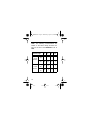
49-2025a.fm Page 1 Wednesday, August 18, 1999 3:07 PM Cat. No. 49-2025A OWNER’S MANUAL Please read before using this equipment. Wireless Infrared Motion Sensor For Use with the Radio Shack Wireless Alarm System (49-2011) 49-2025a.fm Page 2 Wednesday, August 18, 1999 3:07 PM FEATURES Your Radio Shack Wireless Infrared Motion Sensor is for use with the Radio Shack Wireless Alarm System (Cat. No. 49-2011). The sensor works by detecting changes in infrared energy that result from a rapid change in temperature. When anything moves within the sensor’s protected area, the sensor signals the alarm system’s control base. If the base is armed in the Away mode, an alarm sounds. The sensor also periodically sends a status message to the base so it can monitor the sensor’s battery and other information. The sensor includes the following features. Large Protection Area — uses six upper and three lower sectors to protect an area up to 43 feet long by 54 feet wide. 1997 Tandy Corporation. 2 All Rights Reserved. Radio Shack is a registered Trademark used by Tandy Corporation. 49-2025a.fm Page 3 Wednesday, August 18, 1999 3:07 PM Long Range — lets you place the sensor up to 120 feet away from the base (see “Testing the Range” on Page 22). Built-in Tamper Switch — signals the alarm system if someone tampers with the sensor. TEST Button — lets you test the sensor’s range or send a panic signal to the base. PULSE Switch — lets you set the number of movements the sensor detects before signaling the base. ARM/DISARM Switch — lets you easily arm or disarm the sensor. Power-On Inactivity — prevents frequent alarms and saves battery power. Adjustable Head — lets you adjust the sensor’s angle. 3 49-2025a.fm Page 4 Wednesday, August 18, 1999 3:07 PM CONTENTS Installing a Battery ................................ 6 Power-On Activity .............................. 8 Low Battery Indication ....................... 9 Assigning a Zone ................................ 10 Removing a Sensor .......................... 11 Installation ........................................... 13 Choosing a Mounting Location ........ 13 Sensor Coverage ............................ 16 Temporarily Placing the Infrared Motion Sensor ............................................. 19 Testing the Coverage ...................... 20 Testing the Range ........................... 22 Adjusting the Sensor’s Sensitivity ........................................ 24 Adjusting the Sensor’s Angle .......... 25 Setting the Pulse Switch ................. 27 4 49-2025a.fm Page 5 Wednesday, August 18, 1999 3:07 PM Using the Lower-Sector Filter .......... 28 Testing the Installation ..................... 29 Mounting the Sensor ........................ 31 Operation .............................................. 33 Arming/Disarming the Motion Sensor .................................. 33 Using the Built-In Tamper Switch ................................. 35 Using the Panic Alarm ..................... 36 Status Message ............................... 38 Troubleshooting .................................. 39 Specifications ...................................... 42 5 49-2025a.fm Page 6 Wednesday, August 18, 1999 3:07 PM INSTALLING A BATTERY To prepare your motion sensor, you must install a battery and set the ARM/DISARM switch. Your system’s motion sensor requires a 9V alkaline rectangular battery (Cat. No. 23-553). 1. Remove the cover on top of the sensor by removing the screw and then sliding the cover in the direction of the arrow. illus - removing screw and cover 2. Set ARM/DISARM to DISARM. illus - setting ARM/ DISARM 6 49-2025a.fm Page 7 Wednesday, August 18, 1999 3:07 PM 3. Connect the battery terminals to the connector inside the compartment, and place the battery in the compartment on top of the ribbon (for easier battery removal). illus - connecting to the battery terminals Note: Leave the cover off the motion sensor so you can adjust its controls — see “Adjusting the Sensor’s Sensitivity” on Page 24.” 4. Wait about 21/2 minutes for the indicator on the front of the motion sensor to flash; then proceed with the installation. 7 49-2025a.fm Page 8 Wednesday, August 18, 1999 3:07 PM POWER-ON ACTIVITY For about 21/2 minutes after you install or replace the battery, the sensor does not detect motion, send signals to the control base, or respond to the TEST button or internal tamper switch, regardless of the base’s mode. This delay allows the sensor’s movement-detection circuitry to stabilize before operation. After the 2 1/2 minutes, the sensor’s indicator lights briefly if the sensor is disarmed (ARM/ DISARM is set to DISARM). If the sensor is armed (ARM/DISARM is set to ARM), the sensor sends a status message to the control base and the sensor’s indicator flashes, to show that the sensor is ready to operate. Note: When the sensor is disarmed, the status message is sent after about an hour. 8 49-2025a.fm Page 9 Wednesday, August 18, 1999 3:07 PM LOW BATTERY INDICATION When the motion sensor’s battery becomes low, the base’s BATT LOW indicator and the zone indicator for the sensor flash. BATT LOW flashing Replace the sensor’s battery. If the sensor is armed, the sensor sends a status message to the base after about 21/2 minutes. The sensor’s zone indicator lights steadily. If the sensor is disarmed, it sends the status message after about 1 hour. The BATT LOW indicator turns off, and the zone indicator for the sensor lights steadily. 9 49-2025a.fm Page 10 Wednesday, August 18, 1999 3:07 PM ASSIGNING A ZONE Follow these steps to add the infrared motion sensor to your wireless alarm system, and assign it to a zone. 1. Press LEARN on the base. The LEARN indicator flashes. LEARN indicator 2. Enter your access code on the base’s keypad. The base sounds an ascending tone, the LEARN indicator lights steadily, and the indicator for the next unassigned zone flashes. 3. Enter the zone number you want to assign the device to. For example, press 01 to assign the device to Zone 1. 10 49-2025a.fm Page 11 Wednesday, August 18, 1999 3:07 PM Note: If you do not enter the code within 14 seconds, a tone sounds, and the base exits the learn mode. 4. Press TEST on the motion sensor. The system stores the sensor’s settings in the selected zone. The indicator for the selected zone lights steadily and a brief tone sounds to confirm the addition of the sensor (when the tone sounds your device has been learned by the base). The indicator for the next unassigned zone flashes. 5. Press CANCEL on the base to exit the learn mode. REMOVING A SENSOR Follow these steps to remove a motion sensor from the system. When a sensor is removed, it no longer triggers the alarm. 11 49-2025a.fm Page 12 Wednesday, August 18, 1999 3:07 PM 1. Press LEARN on the base to enter the learn mode. Then enter the access code. The base sounds an ascending tone. 2. Enter the zone number for the device you want to remove. The corresponding zone indicator flashes. Note: If you decide not to remove the device for the zone selected, wait approximately 20 seconds for the base to clear the cancel function. 3. Press CANCEL while the zone indicator flashes. The indicator turns off and the device is removed from the system. 4. Press CANCEL again to exit the learn mode. 12 49-2025a.fm Page 13 Wednesday, August 18, 1999 3:07 PM INSTALLATION Follow these steps to properly install the motion sensor. 1. Choose a mounting location. 2. Temporarily place the motion sensor at the mounting location. 3. Test the coverage area and range. 4. Permanently mount the motion sensor. CHOOSING A MOUNTING LOCATION There are some things you should consider when you choose a mounting location for the motion sensor. • The sensor should be mounted on a wall. 13 49-2025a.fm Page 14 Wednesday, August 18, 1999 3:07 PM • The sensor should be mounted 6 1/2 feet high and parallel to the floor for a maximum coverage area of about 43 feet long by 54 feet wide when SENSITIVITY is set to MAX. (When SENSITIVITY is set to MIN, the coverage area for these mounting specifications is about 23 feet long by 31 feet wide.) • The maximum transmission range from the sensor to the base is about 120 feet (in open space with no obstacles). Walls windows, furniture, and other similar objects between the sensor and the control base can decrease the range. Concrete and metal objects decrease the range the most. Mount the sensor where there are as few obstacles as possible between the sensor and the control base. 14 49-2025a.fm Page 15 Wednesday, August 18, 1999 3:07 PM • Mount the sensor where an intruder would move within the sensor’s coverage area. In addition, to avoid false alarms, mount the sensor: • Out of direct sunlight. • Away from heaters or any other device that quickly changes temperature within the coverage area. • Away from air conditioners or other devices that blow air directly on the sensor or create strong drafts within the coverage area. • So the coverage area is above where small pets and children will trigger the sensor. 15 49-2025a.fm Page 16 Wednesday, August 18, 1999 3:07 PM SENSOR COVERAGE The sensor divides its coverage into six upper sectors and three lower sectors. The upper sectors cover a horizontal area 78° wide. The lower sectors cover a horizontal area 60° wide. Notes: • There is a non-coverage area of 2 feet directly in front of the sensor (16 feet with the lower-sector filter installed). • The lower sectors can be disabled. See “Using the Lower-Sector Filter” on Page 28. Both upper and lower sectors cover a vertical area about 20° wide. 16 49-2025a.fm Page 17 Wednesday, August 18, 1999 3:07 PM (illustration: side view of sectors) The sensor’s coverage depends on the height and angle of the sensor, the SENSITIVITY setting, the shape of the protected area, and the texture of the walls and other surfaces in the area. The sensor is most sensitive to motion across the sectors and least sensitive to motion toward or away from the sectors. 17 49-2025a.fm Page 18 Wednesday, August 18, 1999 3:07 PM Note: The following measurements are based on the sensor being mounted 61/2 feet off the floor and SENSITIVITY set to MAX. 0° 5° 15° 30° Long (ft.) 43 28 13 7 Wide (ft.) 54 35 16 8 Long (ft.) 13 10 7 4 Wide (ft.) 12 9 6 3 Sensor Angle Upper Sectors Lower Sectors 18 49-2025a.fm Page 19 Wednesday, August 18, 1999 3:07 PM TEMPORARILY PLACING THE INFRARED MOTION SENSOR Before you permanently mount the motion sensor, temporarily place it at the selected location so you can check the coverage area. You might want to check several locations to determine the best permanent mounting location. One simple way to check the coverage is to place the system on a stepladder at the desired height. Before permanently mounting the system, you must test the coverage and range of the sensor. 19 49-2025a.fm Page 20 Wednesday, August 18, 1999 3:07 PM TESTING THE COVERAGE You must test the sensor’s coverage to be certain it covers the area you want it to monitor. Follow these steps to test the sensor’s coverage. 1. Set the sensor’s ARM/DISARM switch to DISARM . (Illustration: Setting ARM/ DISARM to DISARM. 2. Confirm that the protected area is clear of people, pets, and other potential causes of false alarms. 20 49-2025a.fm Page 21 Wednesday, August 18, 1999 3:07 PM 3. Walk around the protected area and look at the sensor’s indicator. When the sensor detects motion, the indicator lights. 4. If the sensor does not detect your motion, do any or all of the following. • Adjust the sensor angle. See “Adjusting the Sensor’s Angle” on Page 25. • Change the setting of the SENSITIVITY control or PULSE switch. See “Adjusting the Sensor’s Sensitivity” on Page 24 and “Setting the Pulse Switch” on Page 27. • Change the location of the sensor. After you make the adjustments, walk around the protected area again. 21 49-2025a.fm Page 22 Wednesday, August 18, 1999 3:07 PM 5. Walk outside of the protected area. The sensor’s indicator should not light. If it does, find whatever is causing the false alarm and remove it from the area. Repeat Steps 3 and 4. TESTING THE RANGE The range is the distance from which the sensor can transmit a signal to the base. Before you permanently mount your motion sensor, you must test the range. Follow these steps to test the sensor’s range. 1. Press TEST on the base. The TEST indicator lights. (Illustration: The TEST button.) 22 49-2025a.fm Page 23 Wednesday, August 18, 1999 3:07 PM 2. Press TEST on the sensor. The sensor sends a test signal to the base and the sensor’s indicator flashes. (Illustration: TEST on the sensor.) If the base receives the signal, it sounds a short tone. Note: You may need someone to stand next to the base to hear the tone. If the tone does not sound: • The sensor’s battery is low or improperly installed. Check the battery and replace it, if necessary. Then test the range again. 23 49-2025a.fm Page 24 Wednesday, August 18, 1999 3:07 PM • The sensor might be out of the base’s range, or something might be blocking the transmission. Move the sensor or base to another location, then retest the range. 3. Press TEST on the base to exit the test mode. The TEST indicator turns off and the base enters the disarm mode. ADJUSTING THE SENSOR’S SENSITIVITY Using a small, flat-blade screwdriver, rotate SENSITIVITY clockwise (toward MAX ) to increase the sensor’s sensitivity or counterclockwise (toward MIN ) to decrease it. If you have frequent false alarms, rotate SENSITIVITY all the way to the left (MIN). 24 49-2025a.fm Page 25 Wednesday, August 18, 1999 3:07 PM Illus - Adjusting Sensitivity ADJUSTING THE SENSOR’S ANGLE The sensor is attached to a ball and socket joint so you can adjust it to a variety of angles. To adjust the sensor’s angle, loosen the collar screw at the neck of the sensor. Then carefully move the sensor’s head for the desired angle, and tighten the collar screw. 25 49-2025a.fm Page 26 Wednesday, August 18, 1999 3:07 PM To determine the sensor angle, use the supplied angle gauge template (printed on the insert). Place the gauge against the sensor and wall, as shown and rotate the sensor to the desired angle Illus- using the gauge to adjust the sensor angle 26 49-2025a.fm Page 27 Wednesday, August 18, 1999 3:07 PM SETTING THE PULSE SWITCH When the sensor detects a temperature change in its coverage area, it registers the change as a pulse . The setting of PULSE (1, 2, or 3) determines how many pulses the sensor must detect before it signals the base. illus - setting the pulse switch Set PULSE to 1 when you need the sensor to respond immediately; however, this setting is so sensitive that frequent alarms might occur. Set PULSE to 2 to slightly reduce the possibility of false alarms. Set PULSE to 3 for the maximum protection against false alarms. 27 49-2025a.fm Page 28 Wednesday, August 18, 1999 3:07 PM USING THE LOWER-SECTOR FILTER If you experience frequent false alarms caused by pets or small children, you can disable the lower sectors by using the supplied lower-sector filter. See “Sensor Coverage” on Page 16. To install the filter, insert its side tabs into the slots on the sensor window. (Illustration: Installing the lower-sector filter.) 28 49-2025a.fm Page 29 Wednesday, August 18, 1999 3:07 PM TESTING THE INSTALLATION Notes: • To verify proper operation, test the sensor once a week. • This test sounds the alarm. After you mount the sensor, follow these steps to test the installation. 1. Set the motion sensor’s ARM/DISARM switch to ARM. arm/disarm switch 2. Press AWAY on the base. 29 49-2025a.fm Page 30 Wednesday, August 18, 1999 3:07 PM 3. Enter the access code. The 30-second exit delay begins. 4. After 30 seconds, walk around the protected area and watch the sensor’s indicator. It flashes when the sensor signals the control base. Note: If you arm the sensor immediately after you install the battery, the sensor does not detect motion for 2 1/2 minutes. 5. About 45 seconds after the sensor signals the base, the base sounds an alarm. 6. Enter the access code at the base to stop the alarm. 7. After you test the sensor’s installation, make sure ARM/DISARM is set to ARM for proper operation. 30 49-2025a.fm Page 31 Wednesday, August 18, 1999 3:07 PM MOUNTING THE SENSOR After you test the sensor’s coverage and range, follow these steps to mount the sensor. 1. Using the sensor’s bracket as a template, mark the positions for the four wood screws on the mounting surface. (Illustration: Using bracket for template, marking.) 2. Mount the sensor using the supplied wood screws. 31 49-2025a.fm Page 32 Wednesday, August 18, 1999 3:07 PM Note: To allow better access to the screws, loosen the sensor’s collar screw to rotate the sensor’s head and tilt it away from the screw hole. (illustration: rotating sensor head) 32 49-2025a.fm Page 33 Wednesday, August 18, 1999 3:07 PM OPERATION ARMING/DISARMING THE MOTION SENSOR The motion sensor has a separate ARM/ DISARM switch so you can have more options for arming the system. If you install several motion sensors, you can set a particular sensor to DISARM , and then arm the system in the Away mode. The system responds to all types of sensors, but it does not receive signals from the disarmed sensor. The disarmed sensor continues to detect motion and its indicator still lights; however, it does not cause the base to sound the alarm. 33 49-2025a.fm Page 34 Wednesday, August 18, 1999 3:07 PM To arm the motion sensor, set ARM/DISARM to ARM. To disarm the sensor, set ARM/DISARM to DISARM . (illustration: setting switch to Arm & Disarm.) Notes: • In order for the motion sensor to operate as part of your security system, you must set its switch to ARM. • Motion sensors do not arm when you arm the system in the Home mode. 34 49-2025a.fm Page 35 Wednesday, August 18, 1999 3:07 PM USING THE BUILT-IN TAMPER SWITCH Caution: Do not disassemble the sensor. If someone separates the infrared motion sensor bottom panel from the top panel when the sensor is armed, a built-in tamper switch causes the sensor to signal the base. The sensor continues to send the signal as long as the top and bottom panels are separated. To stop the signal transmission, reassemble the panels or set ARM/DISARM to DISARM . To stop the alarm at the base, enter the access code. 35 49-2025a.fm Page 36 Wednesday, August 18, 1999 3:07 PM USING THE PANIC ALARM You can send an immediate panic signal to the control base by pressing TEST on the bottom of the sensor. The panic feature operates when the control base is in any mode other than the test mode. The sensor can be armed or disarmed. Before you use this feature, test it as follows. 1. Disarm the base. 36 49-2025a.fm Page 37 Wednesday, August 18, 1999 3:07 PM 2. Press TEST on the bottom of the sensor. The sensor’s indicator flashes and the control base immediately sounds an alarm. TEST on sensor 3. Enter the access code at the base to stop the alarm. 4. Arm the base and press TEST on the sensor. The base immediately sounds an alarm. Enter the access code at the base to stop the alarm. 37 49-2025a.fm Page 38 Wednesday, August 18, 1999 3:07 PM STATUS MESSAGE The sensor reports a status message to the control base about once every hour, whether the sensor is armed or disarmed. The message includes the sensor ID code, a zone-violation message, and information about the battery condition. If the sensor fails to send a message within 12 hours, the MISSING indicator and the sensor’s corresponding zone indicator flash on the control base. 38 49-2025a.fm Page 39 Wednesday, August 18, 1999 3:07 PM TROUBLESHOOTING If you have problems with the sensor, check the following to correct the problem. If you continue to have problems with the sensor, contact your local Radio Shack store for assistance. If the alarm does not sound after the sensor detects motion, be sure: • The sensor’s battery is installed correctly and has power. • The ARM/DISARM switch is set to ARM. • The control base is armed in the Away mode. • The control base has power. • The sensor is assigned to a zone. 39 49-2025a.fm Page 40 Wednesday, August 18, 1999 3:07 PM • The sensor covers the entire area you want to protect. Move the sensor and/or change its angle, if necessary. • The SENSITIVITY control and/or PULSE switch are set correctly. • The 2 1/2-minute period of inactivity has passed. • The sensor is within range of the control base. Test the range. • The control base’s exit or entry delay period has passed. If there is no panic operation, be sure: • The sensor’s battery is good, and the control base has power. • The control base is in a mode other than the Test mode. 40 49-2025a.fm Page 41 Wednesday, August 18, 1999 3:07 PM • The sensor is assigned to a zone. • The sensor is within range of the base. If you experience frequent false alarms: Find the cause of the false alarms and remove it from the area. You can also adjust the location and angle of the sensor and change the settings of the sensor’s SENSITIVITY and PULSE controls. To prevent false alarms, set SENSITIVITY to MIN and set PULSE to 3. Or, attach the supplied lower-sector filter to disable the lower sectors. See “Using the Lower-Sector Filter” on Page 28. 41 49-2025a.fm Page 42 Wednesday, August 18, 1999 3:07 PM SPECIFICATIONS Power Requirements ...... 9-Volt Alkaline Battery Operating Temperature ................ 32°F to 110°F (0°C to 43.3°C) Sensitivity ................................... 5°F Difference Pulses .................. Selectable (1, 2, or 3 Pulses) Warm-Up Time ............................. 155 Seconds Current Consumption (@ +9V DC): Standby (in arm mode) ........................... 45 mA Alarm (in arm mode with transmission) ... 11 mA Coverage Sensitivity (when angled level at a height of 6.6 feet): Upper Six Sectors (maximum) ............... 43 Feet Upper Six Sectors (minimum) ................ 19 Feet Lower Three Sectors (maximum) .......... 10 Feet Battery Low Voltage ....................... 6.6 Volts DC Accessories ........................... Wood Screws (4) Lower Sector Filter (1) Specifications are typical; individual units might vary. Specifications are subject to change and improvement without notice. 42 49-2025a.fm Page 43 Wednesday, August 18, 1999 3:07 PM Limited Ninety-Day Warranty This product is warranted by Radio Shack against manufacturing defects in material and workmanship under normal use for ninety (90) days from the date of purchase from Radio Shack company-owned stores and authorized Radio Shack franchisees and dealers. EXCEPT AS PROVIDED HEREIN, RADIO SHACK MAKES NO EXPRESS WARRANTIES AND ANY IMPLIED WARRANTIES, INCLUDING THOSE OF MERCHANTABILITY AND FITNESS FOR A PARTICULAR PURPOSE, ARE LIMITED IN DURATION TO THE DURATION OF THE WRITTEN LIMITED WARRANTIES CONTAINED HEREIN. EXCEPT AS PROVIDED HEREIN, RADIO SHACK SHALL HAVE NO LIABILITY OR RESPONSIBILITY TO CUSTOMER OR ANY OTHER PERSON OR ENTITY WITH RESPECT TO ANY LIABILITY, LOSS OR DAMAGE CAUSED DIRECTLY OR INDIRECTLY BY USE OR PERFORMANCE OF THE PRODUCT OR ARISING OUT OF ANY BREACH OF THIS WARRANTY, INCLUDING, BUT NOT LIMITED TO, ANY DAMAGES RESULTING FROM INCONVENIENCE, LOSS OF TIME, DATA, PROPERTY, REVENUE, OR PROFIT OR ANY INDIRECT, SPECIAL, INCIDENTAL, OR CONSEQUENTIAL DAMAGES, EVEN IF Radio Shack HAS BEEN ADVISED OF THE POSSIBILITY OF SUCH DAMAGES. Some states do not allow the limitations on how long an implied warranty lasts or the exclusion of incidental or consequential damages, so the above limitations or exclusions may not apply to you. (continued) In the event of a product defect during the warranty period, take the product and the Radio Shack sales receipt as proof of purchase date to any Radio Shack store. Radio Shack will, at its option, unless otherwise provided by law: (a) correct the defect by product repair without (continued) 43 49-2025a.fm Page 44 Wednesday, August 18, 1999 3:07 PM (continued) charge for parts and labor; (b) replace the product with one of the same or similar design; or (c) refund the purchase price. All replaced parts and products, and products on which a refund is made, become the property of Radio Shack. New or reconditioned parts and products may be used in the performance of warranty service. Repaired or replaced parts and products are warranted for the remainder of the original warranty period. You will be charged for repair or replacement of the product made after the expiration of the warranty period. This warranty does not cover: (a) damage or failure caused by or attributable to acts of God, abuse, accident, misuse, improper or abnormal usage, failure to follow instructions, improper installation or maintenance, alteration, lightning or other incidence of excess voltage or current; (b) any repairs other than those provided by a Radio Shack Authorized Service Facility; (c) consumables such as fuses or batteries; (d) cosmetic damage; (e) transportation, shipping or insurance costs; or (f) costs of product removal, installation, set-up service adjustment or reinstallation. This warranty gives you specific legal rights, and you may also have other rights which vary from state to state. Radio Shack Customer Relations, Dept. W, 100 Throckmorton St., Suite 600, Fort Worth, TX 76102 We Service What We Sell 3/97 RADIO SHACK A Division of Tandy Corporation Fort Worth, Texas 76102 9A7 44 Printed in China