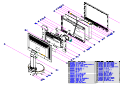
1
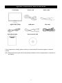
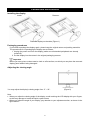
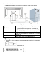
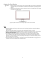
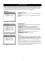
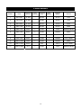
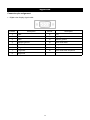
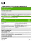
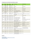
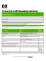
Product End-of-Life Disassembly Instr uctions Product Category: Monitors and Displays Marketing Name / Model [List multiple models if applicable.] HP L2105tm Touchscreen Monitor Name / Model #2 Name / Model #3 Name / Model #4 Name / Model #5 Purpose: The document is intended for use by end-of-life recyclers or treatment facilities. It provides the basic instructions for the disassembly of HP products to remove components and materials requiring selective treatment, as defined by EU directive 2002/96/EC, Waste Electrical and Electronic Equipment (WEEE). 1.0 Items Requiring Selective Treatment 1.1 Items listed below are classified as requiring selective treatment. 1.2 Enter the quantity of items contained within the product which require selective treatment in the right column, as applicable. Quantity of items Item Description Notes included in product Printed Circuit Boards (PCB) or Printed Circuit Assemblies (PCA) With a surface greater than 10 sq cm Main Board / Button Board / Power Board / Camera Board / Arm Board 5 Batteries All types including standard alkaline and lithium coin or button style batteries NA Mercury-containing components For example, mercury in lamps, display backlights, scanner lamps, switches, batteries 4 CCFLs Liquid Crystal Displays (LCD) with a surface greater than 100 sq cm Includes background illuminated displays with gas discharge lamps 1 PCS Cathode Ray Tubes (CRT) NA Capacitors / condensers (Containing PCB/PCT) No Electrolytic Capacitors / Condensers measuring greater than 2.5 cm in diameter or height Capacitor - C101 ( height = 4.6 cm ) 1 External electrical cables and cords Power cord DVI cable VGA cable USB cable Audio cable Gas Discharge Lamps NA EL-MF877-00 Template Revision B Page 1 PSG instructions for this template are available at EL-MF877-01 Plastics containing Brominated Flame Retardants weighing > 25 grams (not including PCBs or PCAs already listed as a separate item above) HB No Components and parts containing toner and ink, including liquids, semi-liquids (gel/paste) and toner Include the cartridges, print heads, tubes, vent chambers, and service stations. NA Components and waste containing asbestos No Components, parts and materials containing refractory ceramic fibers No Components, parts and materials containing radioactive substances No 2.0 Tools Required List the type and size of the tools that would typically be used to disassemble the product to a point where components and materials requiring selective treatment can be removed. Tool Description Tool Size (if applicable) Description #1-SCREW DRIVER ( + ) Medium size Description #2 -SCREW DRIVER ( + ) Small size Description #3 Description #4 Description #5 3.0 Product Disassembly Process 3.1 List the basic steps that should typically be followed to remove components and materials requiring selective treatment: 1. 2. 3. 4. 5. 6. 7. 8. Please see the attachments ( User's Manual and Product Expanded Diagram) 3.2 Optional Graphic. If the disassembly process is complex, insert a graphic illustration below to identify the items contained in the product that require selective treatment (with descriptions and arrows identifying locations). Please refer to the explosion drawing and user’s manual ( Please refer to attachments below) EL-MF877-00 Template Revision B Page 2 PSG instructions for this template are available at EL-MF877-01 USER’S MANUAL HP Compaq L2105tm HSTND-2791-Q First Edition (October 2009) Document Part Number: 582769-001 Copyright © 2008 HP. All Rights Reserved. No part of this manual, including the products and software described in it, may be reproduced, transmitted, transcribed, stored in a retrieval system, or translated into any language in any form or by any means, except documentation kept by the purchaser for backup purposes, without the express written permission of HP. Product warranty or service will not be extended if: (1) the product is repaired, modified or altered, unless such repair, modification of alteration is authorized in writing by HP; or (2) the serial number of the product is defaced or missing. HP PROVIDES THIS MANUAL "AS IS" WITHOUT WARRANTY OF ANY KIND, EITHER EXPRESS OR IMPLIED, INCLUDING BUT NOT LIMITED TO THE IMPLIED WARRANTIES OR CONDITIONS OF MERCHANTABILITY OR FITNESS FOR A PARTICULAR PURPOSE. IN NO EVENT SHALL HP, ITS DIRECTORS, OFFICERS, EMPLOYEES OR AGENTS BE LIABLE FOR ANY INDIRECT, SPECIAL, INCIDENTAL, OR CONSEQUENTIAL DAMAGES (INCLUDING DAMAGES FOR LOSS OF PROFITS, LOSS OF BUSINESS, LOSS OF USE OR DATA, INTERRUPTION OF BUSINESS AND THE LIKE), EVEN IF HP HAS BEEN ADVISED OF THE POSSIBILITY OF SUCH DAMAGES ARISING FROM ANY DEFECT OR ERROR IN THIS MANUAL OR PRODUCT.SPECIFICATIONS AND INFORMATION CONTAINED IN THIS MANUAL ARE FURNISHED FOR INFORMATIONAL USE ONLY, AND ARE SUBJECT TO CHANGE AT ANY TIME WITHOUT NOTICE, AND SHOULD NOT BE CONSTRUED AS A COMMITMENT BY HP. HP ASSUMES NO RESPONSIBILITY OR LIABILITY FOR ANY ERRORS OR INACCURACIES THAT MAY APPEAR IN THIS MANUAL, INCLUDING THE PRODUCTS AND SOFTWARE DESCRIBED IN IT. Products and corporate names appearing in this manual may or may not be registered trademarks or copyrights of their respective companies, and are used only for identification or explanation and to the owners' benefit, without intent to infringe. Agency Regulatory Notices Federal Communications Commission Notice This equipment has been tested and found to comply with the limits for a Class B digital device, pursuant to Part 15 of the FCC Rules. These limits are designed to provide reasonable protection against harmful interference in a residential installation. This equipment generates, uses, and can radiate radiofrequency energy and, if not installed and used in accordance with the instructions, may cause harmful interference to radio communications. However, there is no guarantee that interference will not occur in a particular installation. If this equipment does cause harmful interference to radio or television reception, which can be determined by turning the equipment off and on, the user is encouraged to try to correct the interference by one or more of the following measures: • Reorient or relocate the receiving antenna. • Increase the separation between the equipment and the receiver. • Connect the equipment into an outlet on a circuit different from that to which the receiver is connected. • Consult the dealer or an experienced radio or television technician for help. Modifications The FCC requires the user to be notified that any changes or modifications made to this device that are not expressly approved by Hewlett Packard Company may void the user's authority to operate the equipment. Cables Connections to this device must be made with shielded cables with metallic RFI/EMI connector hoods to maintain compliance with FCC Rules and Regulations. Declaration of Conformity for Products Marked with the FCC Logo (United States Only) This device complies with Part 15 of the FCC Rules. Operation is subject to the following two conditions: 1. This device may not cause harmful interference. 2. This device must accept any interference received, including interference that may cause undesired operation. For questions regarding the product, contact: Hewlett Packard Company P. O. Box 692000, Mail Stop 530113 Houston, Texas 77269-2000 Or, call 1-800-HP-INVENT (1-800 474-6836) For questions regarding this FCC declaration, contact: Hewlett Packard Company P. O. Box 692000, Mail Stop 510101 Houston, Texas 77269-2000 Or, call (281) 514-3333 To identify this product, refer to the Part, Series, or Model number found on the product. Canadian Notice This Class B digital apparatus meets all requirements of the Canadian Interference-Causing EquipmentRegulations. Avis Canadien Cet appareil numérique de la classe B respecte toutes les exigences du Règlement sur le matérielbrouilleur du Canada. Japanese Notice Korean Notice Power Cord Set Requirements The monitor power supply is provided with Automatic Line Switching (ALS). This feature allows the monitor to operate on input voltages between 100–120V or 200–240V.The power cord set (flexible cord or wall plug) received with the monitor meets the requirements for use in the country where you purchased the equipment. If you need to obtain a power cord for a different country, you should purchase a power cord that is approved for use in that country. The power cord must be rated for the product and for the voltage and current marked on the product's electrical ratings label. The voltage and current rating of the cord should be greater than the voltage andcurrent rating marked on the product. In addition, the cross-sectional area of the wire must be a minimum of 0.75 mm² or 18 AWG, and the length of the cord must be between 6 feet (1.8 m) and 12 feet (3.6 m).If you have questions about the type of power cord to use, contact an authorized HP service provider. A power cord should be routed so that it is not likely to be walked on or pinched by items placed uponit or against it. Particular attention should be paid to the plug, electrical outlet, and the point where the cord exits from the product. Japanese Power Cord Requirements For use in Japan, use only the power cord received with this product. CAUTION: Do not use the power cord received with this product on any other products. Product Environmental Notices Materials Disposal This HP product contains mercury in the fluorescent lamp in the display LCD that might require special handling at end-of-life. Disposal of this material can be regulated because of environmental considerations. For disposal or recycling information, contact the local authorities or the Electronic Industries Alliance (EIA)http://www.eiae.org. Disposal of Waste Equipment by Users in Private Household in the European Union This symbol on the product or on its packaging indicates that this product must not be disposed of with your household waste. Instead, it is your responsibility to dispose of your waste equipment by handing it over to a designated collection point for the recycling or waste electrical and electronic equipment. The separate collection and recycling of your waste equipment at the time of disposal will help to conserve natural resources and ensure that it is recycled in a manner that protects human health and the environment. For more information about where you can drop off your waste equipment for recycling, please contact the local city office, the household waste disposal service or the shop where you purchased the product. Chemical Substances HP is committed to providing our customers with information about the chemical substances in our products as needed to comply with legal requirements such as REACH (Regulation EC No 1907/2006of the European Parliament and Council). A chemical information report for this product can be found at http/go/reach. Restriction of Hazardous Substances (RoHS) A Japanese regulatory requirement, defined by specification JIS C 0950, 2005, mandates that manufacturers provide Material Content Declarations for certain categories of electronic products offered for sale after July 1, 2006. To view the JIS C 0950 material declaration for this product, visit http://www.hp.com/go/jisc0950. Table of Contents Safety Instructions ............................................................................................................... 2 Recycling Information .......................................................................................................... 3 System components and accessories ................................................................................ 4 Connection instructions ...................................................................................................... 5 Installing the display...................................................................................................................... 5 Packaging procedures .................................................................................................................. 5 Adjusting the viewing angle .......................................................................................................... 5 Connection instructions................................................................................................................. 6 Using the display .................................................................................................................. 7 Turning on the display................................................................................................................... 7 Function controls........................................................................................................................... 7 Driver Installation Guide for Windows XP .......................................................................... 8 1.Installation .................................................................................................................................. 8 2.Silent install .............................................................................................................................. 10 Control of the Touch Function..................................................................................................... 11 OSD selection ..................................................................................................................... 12 OSD Menu .................................................................................................................................. 12 Troubleshooting ................................................................................................................. 14 Production Specifications ................................................................................................. 15 Preset Modes ...................................................................................................................... 16 Appendix ............................................................................................................................. 17 Connector pin assignment .......................................................................................................... 17 1 Safety Instructions • Please keep the display away from any heat sources such as electric radiators or direct sunlight. Place the display in a stable and well-ventilated place. • The holes or openings on the display are designed for ventilation. Do not cover or block the ventilation holes or openings with any objects. • As the display surface is vulnerable to scratches, avoid touching the surface with nail or pen point. • Shut off the power supply before cleaning. Use a soft lint-free cloth instead of a tissue to wipe the screen. • You may use a glass cleaner to clean the product as required. However, never spray the cleaner directly onto the display surface. • Do not attempt to repair this product yourself! Improperly disassembly of the product may expose you to danger! If your problem cannot be solved according to the "Troubleshooting" guidelines, contact your regional HP authorized service provider, http://www.hp.com/support. 2 Recycling Information HP encourages customers to recycle used electronic hardware, HP original print cartridges, and rechargeable batteries. For more information about recycling programs, go to http://www.hp.com/recycle. 3 System components and accessories LCD display Signal cable (VGA) Quick Start Guide Power cord USB cable Audio cable DVI cable User's manual (CD) Quick Start Guide If any component is missing, please contact your local dealer for technical support or customer service. Note: Please keep the original carton and packing materials for future transportation or shipment of the display. 4 Connection instructions Installing the display Install: Remove: Place the display on the table (Figure 1) Packaging procedures If you need to package the display again, please keep the original carton and packing materials. The procedures for re-packaging the display are as follows: 1. Unplug the power cord from the display (make sure all attached peripherals are already turned off). 2. Put the display into the carton in the original packaging manner. Important Before you start, place a clean towel or cloth on a flat surface, on which you can place the removed display panel without being damaged. Adjusting the viewing angle You may adjust the display's viewing angle from -5° ~ 20°. (Figure 2) Note • When you adjust the viewing angle of the display, avoid touching the LCD display with your fingers, as this may damage or break the liquid crystal screen. • When you adjust the angle of your display, pay attention to your adjustment action, as shown in the figure above. 5 Connection instructions Note: Before installation, please make sure to power off the display and the computer. (Figure 3) 1 Power cord ○ 2 VGA cable ○ 3 Audio cable ○ 4 USB cable ○ Connect one end of the power cord into the AC power connector on the rear of the display, and the other end to an electrical wall outlet. Connect the signal cable: - For analog operation use the VGA cable. Connect the VGA signal cable to the VGA connector on the rear of the PC. - For digital operation use the DVI-D cable. Connect the DVI-D signal cable to the DVI connector on the rear of the monitor and the other end to the DVI connector on the rear of the PC. Connector one end of the audio cable to the audio-in connector on the rear of the display, and the other end of the cable to the audio-out jack on the PC. Connect one end of the USB cable to the USB connector on the display, and the other end of the USB cable to the PC. Warning:: 1. Please verify the video card you are using and use an appropriate signal cable. 2. Pay attention to the PIN assignments and connection directions. Do not force to avoid bending the pins. VGA (D-sub 15 pin) 6 Using the display Turning on the display Turn on the display before turning on the computer. When the power is on, the LED on the power button lights blue and the screen image will appear after about 10 seconds. If the LED doesn't light blue or no image appears, please verify if the display is properly connected. (Figure 4) Function controls 1 MENÚ OSD function menu 2 < Left/decrease button 3 > 4 AUTO 5 POWER Right/increase button Auto adjustment button Power Switch OSD off: Displays the OSD function menu OSD on: Confirm the OSD function option OSD off: Press this button directly to serve as the shortcut for input OSD on: Press this button to select/decrease the adjustment OSD on: Press this button to select/increase the adjustment OSD off: Perform the auto adjustment function OSD on: Exit the OSD function menu Power ON/OFF Blue LED - Power ON mode Orange LED - Power saving mode 7 Driver Installation Guide for Windows XP 1.Installation Step1: Click OTM_Driver_Setup.exe To install OTM driver need OTM devices. If the setup wizard can’t found the OTM devices, it would pop up following warning message. Step2: Click “Next” Welcome message of installation 8 Step3: click “Install” After clicking install, the setup wizard would pop the window which shows the installation process, Step4: Click “Continue anyway” or “Install driver software anyway” When setup wizard is installing OTM driver on XP, the windows system would pop up a warning window. 9 Step5: Click “Finish” Installation Complete Step6: Click Yes After Clicking Finish, the setup wizard would ask the user to reboot computer for runing OTM_Apps applications. 2.Silent install Step 1. Copy OTM_Driver_Setup.exe to a directory Step 2. Execute command prompt Step 3. Change path to the directory Step 4. Type “OTM_Driver_Setup.exe /S” P.S. Silent Install need reboot computer manually. 10 Control of the Touch Function Note: 1. Before using the touch function, make sure that USB is connected, the applications attached to the driver CD-ROM are installed and the Window's operating system is started. 2. When the touch function is active, make sure there is no foreign object in the areas encircled in the figure below. (Figure 5) Make sure there is no foreign object in the encircled areas. Note: • Keep the display away from any heat sources such as electric radiators, natural gas pipes or direct sunlight. Also keep the display away from excessive dust, mechanical vibration or shock. • Retain the original carton & packaging materials. They will be convenient for you, if you need to transport your display again. • For best protection, pack the display in the original manner of package from the factory. • To maintain a brand new appearance of the display, clean with soft cloth regularly. Please remove stubborn stains with soft cleaner rather than strong cleaners such as diluting agent, benzene or corrosive cleaner as they may damage the display. For the sake of safety, remove the power plug prior to cleaning. • The touch function may need about 7 seconds to resume if the USB cable is re-plugged or the computer resumes from sleep mode (suspend mode). 11 OSD selection Press the Menu button to activate the OSD function menu and continue pressing the Menu button to select an option from the 7 functions in the menu. Select the function you want to adjust on the OSD function menu and then press MENU to make adjustment. Please use <or> to adjust the screen to your desired status. After finishing the setting, press AUTO to exit the OSD screen. OSD Menu Brightness/Contrast 2 and ○ 3 in Figure 4) to adjust the Brightness: Press < or > (○ brightness. 2 and ○ 3 in Figure 4) to adjust the Contrast: Press < or > (○ contrast. IMAGE CONTROL Auto Adjustment: Automatically selects the optimal settings for image paramenters. H.POSITION: Controls the picture’s horizontal position. V.POSITION: Controls the picture’s vertical position. CLOCK: Sets up the internal clock. Larger values make the displayed image appear wider; smaller values make it appear compressed. PHASE: Adjusts the internal clock’s time lag in order to optimize the screen image. SHARPNESS: Controls image sharpness. COLOR This menu lets you select a preset color temperature (9300K, 6500K or sRGB) by pressing the OSD buttons < or >. Changes to the color temperature take immediate effect on screen. If you wish to set individual color values, select the Custom Color option. Then press the MENU button to select the red, green and blue settings and set the desired value using the OSD buttons < or >. The current settings are automatically saved when you return to the previous level or exit the OSD menu. 12 OSD CONTROL H.OSD POSITION: Controls the OSD menu’s horizontal position. V.OSD POSITION: Controls the OSD menu’s vertical position. OSD TIMEOUT: Determines how long (in seconds) the OSD menu waits before closing automatically after no action has been performed. OTHER LANGUAGE: OSD menu language selection: ENGLISH,DEUTSCH,FRANCAIS,ESPANOL,ITALIANO,POLSKI, NEDERLANDS,PYCCKO. INPUT: Selects Analog (D-sub) or Digital (DVI-D) input. SPEAKER VOLUME: Adjusts the monitor loudspeaker output volume. INFORMATION: There is an optional OSD window (on/off) that displays the newly adjusted screen resolution settings. Note: Do not adjust the screen setting when animation is displayed; make sure to adjust the setting in full screen mode. 13 Troubleshooting Problems Possible solutions Power LED doesn't light up. • Check if the power switch is in the ON position • Make sure the power cord is properly connected No screen image • • • • Abnormal colors are present • Please refer to the "Color Temperature" section to adjust the RGB color or select a color temperature. The image bounces or a wave pattern is present • Remove any electrical device that may be causing electrical interference. • Check the signal cable and make sure the pins are not bent. The screen image is not centered or the size is incorrect • Press the Auto button to automatically optimize the display status. • Refer to the "Image Control section". Check if the power switch is in the ON position Make sure the power cord is properly connected Make sure the signal cable is securely connected When the display is in use, it will automatically turn off to enter the power saving mode. Please press any key to see if the image resumes. Note: Never disassemble or repair the product yourself. If your problem cannot be solved according to the troubleshooting guidelines, please contact your local dealer. 14 Production Specifications LCD panel size 54.61 cm(21.5in) DCR 3000:1 (typical) Viewing angle Horizontal 170°, vertical 160° (typical) Response time 5 ms (typical) Brightness 300 cd/m2 (typical) Input signal Analog signal (D-sub); digital signal (DVI) Display color 16.7 M colors Frequency 24 ~ 83 kHz Horizontal, 50 ~ 76 Hz Vertical Max resolution 1920 x 1080(60Hz) Max Pixel clock 180 MHZ Tilt -5° ~ 20° Audio output 1W X 2 Power supply 100-240VAC, 50/60Hz, 1.2A(1,2A) Power consumption Display mode: Max 48W; LED color: Blue Sleeping mode: Less than 1W, LED color: Orange Width: 513 mm, Height: 393 mm, Depth: 228 mm Width: 20.2 in, Height: 15.5 in, Depth: 9 in 8.5 kg/18.7 lb (net) Size Weight Environmental conditions Operating temperature/humidity: 5 ~ 35°C, relative humidity: 10-85% Storage temperature/humidity: 5 ~ 35°C, relative humidity: 10-85% 15 Preset Modes Preset Pixel Horz Freq (kHz) Horz Polarity Vert Freq (Hz) Vert Polarity Pixel Clk (MHz) Source 1 640 x 480 31.469 - 59.940 - 25.175 VGA 2 720 x 400 31.469 - 70.087 + 28.322 VGA 3 800 x 600 37.879 + 60.317 + 40.000 VESA 4 1024 x 768 48.363 - 60.004 - 65.000 VESA 5 1280 x 720 45.00 + 60.00 + 74.25 VESA/CEA-861D 6 1280 x 960 60.00 ± 60.00 ± 108.000 VESA 7 1280 x 1024 63.98 + 60.02 + 108.000 VESA 8 1440 x 900 55.94 - 59.89 + 106.500 CVT 1.30MA 9 1600 x 1200 75.00 + 60.00 + 162.000 VESA 10 1680 x 1050 65.29 - 60.0 + 146.25 CVT 1.76MA 11 1920 x 1080 67.5 + 60.00 + 148.5 VESA/CEA-861D 16 Appendix Connector pin assignment • 15 pin color display signal cable: PIN No. Description PIN No. Description 1. Red 9. +5V 2. Green 10. Logic ground 3. Blue 11. Monitor ground 4. Monitor ground 12. DDC-serial data 5. DDC-return 13. H-sync 6. R-ground 14. V-sync 7. G-ground 15. DDC-serial time sequence 8. B-ground 17