1
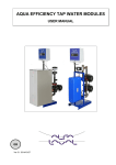
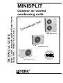
MINISPLIT
Single Circuit Cooling only and Heat Pump Systems
Models MOC / MOH 07 to 55 G Series
TECHNICAL GUIDE
Outdoor air cooled
condensing units
n
e
i
b
m
a
w
Lo
“
”
e
n
i
l
t
MOC /MOH 45 to 55
MOC /MOH 25 & 35
R407c
MOC / MOH 07 to 18
YORK
®
List of contents
Page
1 -Safety .....................................................................................................................................................................................3
2 -Outdoor units ......................................................................................................................................................................3
3 -Technical Specifications ................................................................................................................................................3
4 -Dimensions ..........................................................................................................................................................................4
5 -Installation ............................................................................................................................................................................5
6 -Refrigeration circuit connections ...............................................................................................................................6
7 -Electrical connections .....................................................................................................................................................7
8 -Defrost ....................................................................................................................................................................................8
9 -Regulator ..............................................................................................................................................................................9
10 -Trouble-shooting guide ............................................................................................................................................... 10
11 -Accessories .......................................................................................................................................................................12
12 -Technical Appendix .......................................................................................................................................................12
Minisplit unit start-up check-list
Parts List : (Contact York)
Decommissioning, Dismantling and Disposal
Product designation
MOC
25
G
15
PDFGH
Factory fitted options
P:
Q:
D:
F:
G:
H:
Type
MOC : Minisplit Outdoor unit, cooling only
MOH : Minisplit Outdoor unit, heat pump
rotary compressor
scroll compressor
pressure operated low temperature kit
hot gas bypass valve
crankcase heater not fitted as standard
compressor starting kit
Voltage code
15 = 220-240V/1Ph/50Hz
35 = 380-415V/3Ph/50Hz
Size in MBTU/h
07 =
09 =
12 =
18 =
25 =
35 =
45 =
55 =
2
2 kW
2.4 kW
3.4 kW
5.0 kW
6.3 kW
8.6 kW
12.0 kW
13.8 kW
R407C
For all correspondance with YORK, please
state complete machine references and
serial numbers.
1 - Safety
2 - Outdoor units
Installation and maintenance of this air conditioning system
should only be carried out by trained and qualified personnel.
Regular maintenance operations such as cleaning the coils
and air filters must be performed to keep the units in proper
operating condition.
The units are shipped complete with a charge of R407c refrigerant sufficient for a piping length of 7,5 metres.
CAUTION
The unit support plate is shaped in such a way that water produced during defrost operations on heat pump units is collected at a single point where it can be easily drained off. No
accessory drain pan is required.
Before undertaking any work on the unit, make sure that the
power supply has been disconnected.
ELECTRICAL CONNECTIONS
All electrical wiring and connections must comply with local
standards.
GENERAL PRECAUTIONS
Check that the power supply available agrees with nameplate
voltage.
Use adequate line protection.
The unit must be grounded.
3 - Technical specifications
Model
Outdoor unit
Indoor unit
Cooling and heating
MCC-MCH
MHC-MHH
MKC-MKH
MAC-MAH
kW
kW
kW
kW
Compressor
Refrigerant
Type
Location
Power supply
V/Ph/Hz
kW
Power input
A
Nominal current
Starting current
A
dB(A)
Noise level at 2,5m
H (mm)
W (mm)
Overall dimensions
D (mm)
kg
Net weight MOC
kg
Net weight MOH
Type of connection
Piping
Gas
Diameter
Liquid
Refrigerant charge MOC / MOH
g
Air flow
m3/h
Number of fans
Expansion device
The Nominal Cooling Capacity is based on :
- Indoor Air Temp. 27°C DB / 19°C WB
- Outdoor Air Temp. 35°C DB
Piping Length : 5 meters
07G
2,0
-
09G
2,4
2,2
-
12G
3,4
3,2
3,3
Rotary
MOC-MOH
25G
18G
4,7
6,3
4,6
6,0
5,0
6,2
4,7
6,3
35G
8,6
8,4
8,6
8,6
45G
12,0
12,0
12,0
Scroll
55G
13,8
13,8
13,8
R 407C
Capillary
Restrictor
Indoor unit
Outdoor unit
380-3-50
220/240-1-50
0,7
0,89
1,68
2,6
3,6
1,25
3,2
4,3
3,4
4,1
7,7
12,4
5,6
7,8
5,9
6,6
17
23
35
81
60
62
47
46
40
40
40
51
52
53
52
46
492
492
696
1142
1142
900
590
492
764
764
850
1060
1060
1060
820
764
230
230
287
345
345
345
280
230
32
38
42
68
121
107
132
62
34
40
43
69
122
108
133
63
Flared connection with nut
3/8"
1/2"
5/8"
3/4"
3/8"
5/8"
5/8"
3/4"
1/4"
1/4"
3/8"
3/8"
1/4"
3/8"
3/8"
3/8"
680 / 620 720 / 1000 1150
1880
2100
3650
3000
4000
1 220
1 220
3 310
3 310
3 832
4 748
7 885
1 220
1
1
1
1
1
1
2
2
The Nominal Heating Capacity is based on :
- Indoor Air Temp. 21°C DB
- Outdoor Air Temp. 7°C DB/6°C WB
Piping Length : 5 meters
3
4 - Dimensions
Overall dimensions
MOC/MOH 07 to 18
MOC/MOH 25 to 35
W
L
L
MOC/MOH 45 to 55
W
L
W
Distances between mounting hole centres
MOC/MOH
L (cm)
W (cm)
07-09-12
18
25
35 - 55
49.7
51.7
55
74
24,8
29.6
31.5
37.5
Outdoor unit clearances
A minimum of clearance is necessary around the units to ensure proper air circulation and easy access for maintenance.
MOC/MOH 07 to 18
MOC/MOH 25 to 35
MOC/MOH 45 to 55
A
A
A
B
D
B
4
E
D
E
C
C
07 to 18
E
B
25
MOC - MOH
35
45
55
A
500
300
300
300
300
B
200
500
600
600
600
C
100
100
100
100
100
D
600
600
800
800
800
E
190
210
210
210
300
C
D
5 - Installation
Unit installation entails:
- unit mounting
- refrigerant piping connections
- condensate water drainage connections
- unit wiring connections.
OK
Whatever type of installation is chosen for the unit,
the following installation rules must be observed:
- The location selected for unit installation must be
capable of withstanding the weight of the unit in its full
operating configuration.
- In particularly windy places, the unit should be installed so that the prevailing wind does not interfere with
air discharge from the unit (configuration with the wind
blowing onto the side of the unit).
- If the outdoor unit is installed on the ground, make
sure that the location is not liable to flooding.
- MOH heat pump unit : install the unit at least 10 cm
above ground level to facilitate drainage of defrost
water and prevent accumulation of ice. In eff e t ,
defrost water can cause accumulation of ice under the
unit during sub-freezing outdoor temperatures.
- Make sure that you know and apply any and all local
rules and regulations concerning the installation of air
conditioning equipment.
- Wherever possible, install the unit where it will be protected from rain, snow and run-offs from overhanging
structures.
- Use the vibration isolators provided to prevent vibration transmission and resulting unnecessary noise.
- In areas with heavy snowfall it is best to install the unit
on wall supports.
- Do not install the equipment in explosive environments.
- If condensates are not to be drained, do not install the
elobow supplied with the unit.
- Make sure that the surrounding atmosphere does not
contain noxious or dangerous substances such as oil
vapours or sulphur.
- Make sure that the unit is installed level so that
condensates will drain off correctly.
- Select a location where neither dust nor other foreign
bodies will clog the unit coil.
- If the air conditioner is installed in a polluted area,
increase the frequency of maintenance operations.
- Avoid installing the unit where it will be in direct sunlight, especially if it is a cooling only model since
direct sunlight will increase condensing pressure and
reduce unit efficiency. Install units facing North whenever possible.
- In some regions, it is necessary to heat the bottom of
the condensate drainage pan and the condensate
drainage piping to avoid ice formation, and resulting
ice build-up in the fan compartment (heater strip must
be at least 25 W/m).
- All devices using fitted with electronic equipment are sensitive to lightning. It is therefore wise to protect the installation with a surge arrestor.
5
6 - Refrigerant circuit connections
Make piping runs as short as possible and avoid all unnecessary changes in direction or elevation.
Insulation
To prevent heat loss, the two lines must be insulated separately
Use an appropriate bending tool to form curves and avoid flattening the refrigerant tubes.
Fix piping with pipe clamps and make sure that any eventual
pipe vibrations cannot be transmitted to the building structure.
Use refrigeration quality piping only with an operating pressure
rating of at least 30 bars. Never use ordinary «plumbing» quality
piping : you MUST use special de-oxidised, dehydrated, refrigerant quality copper piping.
Minimum thickness 6 mm
Heat pump
(discharge)
L
Pipe lengths
Liquid
• Maximum piping lengths
MOC-MOH 07
D (m)
10
L (m)
15
H (m)
7
09
10
15
7
12
10
15
7
Gas
D
18
10
15
7
25
15
25
10
35
15
25
10
45
15
25
10
Cooling
55
15
25
10
Note : Where the difference in elevation between the indoor
unit and the outdoor unit is greater than 5 metres, install
an oil trap every 5 metres.
Cooling
(suction)
Heat pump
(discharge)
L
The suction line must have a 2% gradient up to the compressor
on horizontal sections.
Where piping lengths are unusually long and include a large
number of oil traps, it may be necessary to adjust the compressor oil charge.
Heat Pump
Liquid
• Refrigerant charge to be added per extra 5 meter of
piping length
MOC-MOH
g/m
07
15
09
15
12
15
18
65
25
65
35
65
45
65
Cooling
(suction)
55
65
Refrigerant piping connections
(FLARE connections)
Low pressure
To avoid alteration of unit capacities, make sure that piping
lengths and changes in elevation are kept to a strict minimum.
- Open the service valves and top up the refrigerant charge if
necessary.
6
Cooling
High pressure
Manifold
Before connecting the refrigerant lines, follow the procedures
below (if pre-charged connection lines are not supplied) :
- Select copper pipe diameters according to the size of unit to
be installed.
- Install the refrigeration lines, making sure that no foreign
bodies get inside the piping.
- Install the flare connectors and flare the ends of the pipes.
- Evacuate the piping. This operation, which should last at least
15 minutes or even longer if there are large piping lengths and
changes in elevation, should be followed by a leak test. To this
effect, when the piping has been evacuated, close the pressure guage tap, note the value on the guage, then wait for 15
minutes. If the needle moves, there is a leak in the system.
Make the necessary adjustments or repairs and repeat this
procedure until the needle no longer moves. For greater precision, use a vacuometer, or pressurise the installation with 25
bars of dry nitrogen.
H
Gas
Pressure Liquid valve
tap
MOC/MOH 25 G
Outdoor unit
Gas valve
Indoor unit
Gas line
Liquid line
R407C
7 - Electrical connections
MOC 07 - 25 - Cooling only
E
E
A
MOH 07 - 25 - Heat pump
Indoor unit
N
1
2
N
1
2
E
E A
N
1
2
N
1
2
Indoor unit
3
3
Outdoor unit
Power supply
220V/1Ph/50Hz
Outdoor unit
Power supply
220V/1Ph/50Hz
MOC 35 - 55 - Cooling only
E
N
E R
1
S T
2
N
1
MOH 35 - 55 - Heat pump
Indoor unit
2
E
N
1
2
3
Indoor
unit
E R
S T
N
1
2
3
Outdoor unit
outdoor unit
Power supply
380V/3Ph/50Hz
Power supply
380V/3Ph/50Hz
Wire sizes
MOC / MOH
Power supply
07
09
mm2
12
18
25
3 x 2,5
Interconnection
Cooling mm
4 x 2,5
(Ind./Out.)
Heating mm 2
5 x 2,5
A
10
45
55
5 x 2,5
2
Fuse (Slo-blow)
35
16
20
Terminals N and 1 (see diagrams above) correspond to power
supply to the indoor unit coming from the outdoor unit.
Compressor power supply is established by terminal 2.
Power supply to the 4-way valve is established by terminal 3.
16
20
For further details on wiring of these units, see the diagrams pasted inside each unit.
7
8 - Defrost
Defrost is handled via a defrost management electronic control
board (model with two potentiometers and 6 dip switches, see
diagram n°2). This enables defrost cycles to be initiated when
the temperature reaches -5°C at the condenser coil bend. The
end of defrost cycle set point is +10°C. The duration of the
defrost cycle varies depending on operating conditions but it is
limited to a maximum of 10 minutes. Time delay between successive defrost cycles is 30 minutes.
ON
Transformer
Transformateur
1 2
34
The time delay between successive defrost cycles and the maximum duration of each cycle are adjustable. If these need to be
modified, please contact YORK first for technical advice.
- Low and high pressure switch settings on units :
MOC/MOH 35-45-55-65 LP = 1.5 Bars
HP = 28 Bars
➀
Start of defrost cycle temperature
adjustment potentiometer
➁
End of defrost cycle temperature
adjustment potentiometer
③
"Dip Switches" for adjusting time
delay between defrost cycles and
maximum defrost cycle duration.
➃
Female sensor connection
⑤
Shunt these terminals to simulate a
defrost cycle
5 6
DEF
Depending on the climate, it may be necessary to adjust defrost
cycle start and end temperatures.
This is done with a screwdriver : adjust potentiometers 1 and 2 .
8
The defrost cycle can be forced into action by shunting terminals
DEF on the defrost control board in the outdoor unit.
Diagram n°2 - Adjustable Defrost Control Board
Once the adjustment has been made, Disconnect the main
power supply, wait 2 to 3 seconds then reconnect the power
supply to reset the defrost control board.
9 - Regulator
9.1 - Low temperature kit
Installation of the low temperature kit should be envisaged
whenever a unit must operate in cooling mode (in heating mode
the kit is bypassed), at temperatures below the standard operating
limits. If the kit is not installed and the unit is operated under
such conditions, condensing pressure will be so low that the indoor
unit coil will become frosted.
The function of the pressostatic low temperature kit is to maintain
condensing pressure at a constant value, when the outdoor
temperature drops, by reducing the speed of the fan on the outdoor
unit.
Condensing temperature can be measured by a direct pressure
reading using the Schrader valve. Factory setting is 16 bars, i.e.
45°C. Condensing pressure to be maintained is adjustable if
necessary (ref a) with a screwdriver.
The condenser fan is controlled proportionnaly by a triac.
Minimum voltage supplied by the controller is 45% of input
voltage. This is a fixed value.
If for climatic reasons, condenser fan speed has to be reduced,
complete stoppage of the fan can be obtained below the minimum
voltage attained. Set the selector (ref b) on the "Cut Of” position to
obtain fan stoppage. The initial position is “Min. Speed”.
9.2 - High pressure switch (inter-season starting kit) for MOH
This high pressure switch is only active in the heating mode and
controls a hot gas bypass valve.This control device opens the hot
gas bypass valve at 25bars and cuts out at 17 bars.
It is usually activated during the following phases :
- Start-up when the conditioned space is cold and the coil on the
air handling unit is at a temperature lower than 35°C (indoor
fan does not operate at coil temperatures lower than 35°C in
the heating mode).
- Final phase of defrost cycle.
- Start-up in heating mode during the inter-season.
9
10 - Trouble-shooting guide
Note : Open the main unit power switch before proceeding with any repair operations.
Symptoms
Cause
Remedy
No heating or cooling
The compressor and outdoor fan do not
operate
The outdoor fans runs but the compressor will not start
Power failure
Contact the electrical utility company
Fuse blown or circuit breaker open
Replace the fuse or reset the breaker
Voltage is too low
Find the cause and fix it
Faulty contactor, thermostat or relay
Replace the faulty component
Electrical connections loose
Retighten the connections if necessary
Faulty capacitor (single phase models)
Find the cause, then replace capacitor
Thermostat adjustment too low (in heating mode) or
too high (in cooling mode)
Change thermostat setting
Incorrect wiring, terminals loose
Check and retighten
Pressure switch tripped (depending on model)
Find the cause, then reset
Motor windings cut or grounded
Check the wiring and the compressor winding resistance
Faulty capacitor (single phase models)
Find the cause, then replace capacitor
Insufficient heating or cooling
Low refrigerant charge
Make sure there are no leaks
Remove charge, repair, evacuate and recharge
Insufficient airflow
Check the air filter, the damper positions. Check that
air is not being recycled
Clean or replace, set the air damper to the right position
Check cleanliness of unit coils
Clean the coils
Capillaries obstructed or orifice plugged (humidity)
Remove charge, repair, evacuate and recharge
Liquid and gas lines insulated together
Insulate them separately
Systems operates for long periods or continuously
The compressor runs continuously
Thermostat adjustment too high (in heating mode) or
too low (in cooling mode)
Change the setting
No fan operation or faulty fan
Check condenser air circulation
Refrigerant charge too low, leakage
Find leak, repair and recharge
Heating/cooling load underestimated
Reduce load or use next unit size up
Air or incondensables in refrigerant circuit
Remove charge, evacuate and recharge
Unit short-cycles
The compressor starts but shuts down
quickly on thermal protection
10
Too much or too little refrigerant
Remove charge, evacuate and recharge
Air or incondensibles in refrigerant circuit
Remove charge, evacuate and recharge
Faulty compressor
Determine the cause and replace compressor
Power supply voltage too high or too low
Solve the problem
Faulty condenser (single phase models)
Determine the cause and replace
Faulty thermostat
Replace
Restriction in the refrigeration circuit
Find restriction and repair.
Frosted or plugged expansion device
Remove charge, evacuate and recharge
Poor airflow on indoor or outdoor unit
Clean the coil and the filter if necessary, check that
motors are operating properly
Faulty power supply
Check wire guages, etc
Changeover valve damaged or blocked open (heat
pump units)
Replace it
10 - Trouble-shooting guide (Cont’d)
Frosted indoor coil
Ice build-up on indoor coil
Low refrigerant charge, refrigerant leak
Repair the leak and recharge
Insufficient airflow
Check the condition of the air filters
Check the cleanliness of the indoor coil
Check fan motor operation
Check that the air damper opens correctly (on units
equipped with a damper)
Low operating temperature limit exceeded
Install a low temperature kit
Unit noisy
Faulty installation
Compressor noisy
Make sure vibration isolators have been installed.
Check piping collars.
Tighten any loose components
Make sure that the compressor is not losing oil
Repair and add oil
Excessive oil or refrigerant charge
Remove excess charge
Electric heat does not work (on indoor units fitted with this option)
Thermostat
Thermostat incorrectly adjusted
Readjust the thermostat
Repair or replace the thermostat
Safety device
Check continuity through fuse
Replace faulty elements
Safety thermostat opens
Check indoor unit airflow
Check cleanliness of air filter and coil
Open air balancing dampers
If ducts are long, inhibit low, and perhaps even
medium fan speeds
Faulty unit wiring
Check that wiring complies with applicable diagrams
Excessive or insufficient discharge pressure
Excessive discharge pressure
Insufficient discharge pressure
Outdoor coil dirty
Clean the coil
Indoor unit fan (heating mode) or outdoor unit fan
(cooling mode) faulty
Replace the fan
Excessive refrigerant charge
Remove excess charge
Air or incondensables in refrigerant circuit
Check the circuit, evacuate, and recharge
Refrigerant charge too low
Find and repair the leak, top up refrigerant charge
Liquid line blocked or crushed
Find obstructions and eliminate them.
Compressor valves worn out or leaking
Replace the compressor
Excessive or insufficient suction pressure
Excessive suction pressure
Insufficient suction pressure
Refrigerant overcharge
Remove excess refrigerant
Cycle changeover valve faulty or leaking (heat pump
units)
Replace the valve
Low refrigerant charge
Add some refrigerant
Outdoor unit coil (heating mode) or indoor unit coil
(cooling mode) frosted
Find cause and fix it
Insufficient airflow on the outdoor unit coil (heating
mode) or the indoor unit coil (cooling mode)
Make sure that the indoor or outdoor unit fan is operating properly
Suction line obstructed
Find obstruction and eliminate
Expansion device obstructed or iced up.
Remove charge, evacuate, recharge
Poor contact the line and and the defrost sensor in the
heating mode (heat pump units)
Reinstall the sensor correctly using a contact compound. Insulate the assembly
Condenser airflow too high (in the cooling mode) in
relation to outdoor air temperature
Install a low temperature kit
11
11 - Accessories
Floor supports and wall supports
Type
of support
Floor
Wall
MOC-MOH
Ref.
A
B
C
07 to 18
25 to 55
07 to 12
18
25 to 55
AMF44B
AMF50A
AMW42A
AMW50A
AMW65A
350
500
420
495
650
100
100
500
600
750
100
100
44
44
44
A
B
Model AMW65A
only
C
B
A
C
Wall mounting support
Floor support
12 - Technical appendix
Unit Capacity
Capacity correction factor for piping length (C2)
Total cooling capacity can be determined by using correction factors C1, C2 and C3.
Given cooling capacity = Cooling capacity at standard rating
conditions x C1 x C2 x C3.
Indoor unit
Piping length (m)
7.5
10
1
0.98
Correction factor C2
C1 = Capacity correction factor for temperature
C2 = Capacity correction for piping length
C3 = Capacity correction for indoor unit fan speed
Capacity correction factor for indoor fan speed (C3)
Indoor unit
Capacity correction factor for temperature (C1)
Fan speed
Cooling capacity correction factor
Indoor Temperature
°C WB
23
19
14
19
1.10
0.88
Correction factor C3
Outdoor Temperature °C DB
25
30
35
40
1.20
1.08
0.86
1.15
1.04
0.84
1.11
1
0.82
1.06
0.96
0.79
46
1
0.90
0.74
Heating capacity correction factor
Medium
Low
1
0.90
0.75
Operating temperature limits
Cooling mode
Heating mode
Maximum
Minimum
+46°C
0°C
(-10°C with fan stoppage)
+28°C
(heat pump mode)
-10°C
Outdoor Temperature °C WB
Indoor Temperature
12
High
°C DB
23
14
1.20
10
1.04
6
0.96
0
0.77
-8
0.58
20
17
1.25
1.30
1.10
1.13
1
1.04
0.80
0.83
0.69
0.63
Correction factors (C1) determine the instantaneous capacity
(which does not take account of defrosting on heat pump units).
These capacities may vary slightly, depending on the size of the
unit.
12 - Technical appendix (cont’d)
Cooling circuit diagrams
Outdoor unit
Indoor unit
Outdoor unit
Cooling only - MOC 07-09-12-18-25
Indoor unit
Heat pump - MOH 07-09-12-18-25
Legend:
1. Compressor
2. Outdoor unit coil
3. Capillary tube
4. Indoor unit coil
5. Refrigerant circuit piping
6. Isolating valve with pressure tap
Outdoor unit
7.
8.
9.
10.
11.
High pressure switch (intermediate season safety in heating mode)
Anti-slugging receiver
4-way cycle changeover valve
Non-return valve
Pressure operated low temperature kit (activated in cooling mode)
Indoor unit
Outdoor unit
Cooling only - MOC 35-45-55
Indoor unit
Heat pump - MOH 35-45-55
Legend
1. Compressor
2. Outdoor unit coil
3. Combined HP/LPpressure switch (manual reset for the HP switch)
4. Indoor unit coil
5. Refrigerant circuit piping
6. Isolating valves with pressure taps
7.
9.
10.
11.
12.
HP pressure switch (interseason start-up safety in heating mode)
4-way cycle changeover valve
Anti-slugging receiver
Restrictor
Pressure operated speed control (activated in cooling mode)
13
YORK
®
Contractor
Location :
Order/invoice number :
Installation start-up date :
Minisplit unit start-up check-list
Equipment reference numbers
Indoor unit
Outdoor unit
Type
Type
Serial Number
Serial Number
Power supply and unit
Single phase
3 Ph1-2 =
V
A Neutral
interconnection cables
Ph/N =
V
Ph2-3 =
V
A
yes
with corresponding currents
Ph =
A
V
A
no
Ph3-1 =
2
Power supply cable
Guage =
mm Length =
Interconnection cable
Guage =
mm2 Length =
Type of line protection
Type
Current =
Check that all electrical connections are tight and that the unit is properly earthed
Refrigeration piping
Ø liquid =
in. l. liquid =
Ø gas =
in. l. gas =
Position of indoor unit
Height of the unit =
m Height of the room =
Dif. in elevation between units
indoor > outdoor
m ext > int
Changes in direction
Number of oil traps =
Number of bends =
Condensate pump
Pumping height =
m Type of drainage =
Condensate drainage
U-Bend
❑ yes
❑ no Ø drainage piping =
Evaporator
Return air temperature =
°C Air discharge temp. =
Condenser
Inlet air temperature =
°C Outlet air temp. =
Temperature measurements
Superheat =
°C Sub-cooling =
Low temperature kit
❑ yes
❑ no
Fan rotation correct (direction)
❑ yes
❑ no
Suction pressure
LP at low speed =
Bar LP at high speed =
Discharge pressure
HP at low speed =
Bar HP at high speed =
Compressor Amps
I at low speed =
A
I at high speed =
Control thermostat
cut out (open)=
°C cut in (closed) =
Low pressure switch
trip =
Bar reset =
High pressure switch
trip =
Bar reset =
Refrigerant charge top-up
❑ yes / quantity =
g
❑ no
Oil top-up
❑ yes / quantity =
g
❑ no
Checked unit charge
❑ yes
❑ no
Check that you have : ✓
✓
✓
✓
✓
✓
✓
✓
Completely opened the isolating valves.
Insulated the gas and liquid lines separately.
Tightened all flare connections.
Leak-tested the entire installation.
Evacuated the refrigeration circuit.
Tested all functions of the air conditioner in the heating and the cooling mode.
Tested the crankcase heater for correct operation.
Installed the units in accordance with all instructions given in the documentation.
Name, address and phone number of your contractor :
14
Earth
yes
no
m
m
A
m
m
m
m
cm
°C
°C
°C
Bar
Bar
A
°C
Bar
Bar
CONFORMITY DECLARATION
FOR MACHINES
WE:
C.R. YORK, S.L.
PASEO ESPRONCEDA, 278, 08.204 SABADELL
DECLARE UNDER OUR OWN RESPONSIBILITY THAT THE MACHINE:
DESIGNATION:
Split System Outdoor Unit
TYPE:
MOC 07 to 55 and MOH 07 to 55
SERIAL NUMBER:
IS IN COMPLIANCE WITH THE REQUIREMENTS OF:
•APPLICABLE EEC DIRECTIVES 89/392/EC, 89/336/CEE
• NATIONAL STANDARDS AND TECHNICAL SPECIFICATIONS ISO 9001, (Pr EN378)
AND IN ACCORDANCE WITH THE FOLLOWING HARMONIZED STANDARDS
• EN60204-1, EN292-1, EN292-2, EN563, EN294, EN953, EN55014, EN60555-2,
EN50082-1
NAME
SURNAME
POSITION
SIGNATURE :
: KACHIT
: SRIMUNCHU
: Quality Manager
DE-COMMISSIONING DISMANTLING & DISPOSAL
This product contains refrigerant under pressure, rotating parts, and electrical connections which may be a danger and cause injury !
All work must only be carried out by competent persons using suitable protective clothing and safety precautions.
Read the Manual
1.
2.
3.
4.
Risk of electric shock
Unit is remotely controlled and
may start without warning
Isolate all sources of electrical supply to the unit including any control system supplies switched by the unit. Ensure that all points of electrical and gas isolation are
secured in the OFF position. The supply cables and gas pipework may then be disconnected and removed. For points of connection refer to unit installation instructions.
Remove all refrigerant from each system of the unit into a suitable container using a refrigerant reclaim or recovery unit. This refrigerant may then be re-used, if
appropriate, or returned to the manufacturer for disposal. Under NO circumstances should refrigerant be vented to atmosphere. Where appropriate, drain the
refrigerant oil from each system into a suitable container and dispose of according to local laws and regulations governing disposal of oily wastes.
Packaged units can generally be removed in one piece after disconnection as above. Any fixing down bolts should be removed and then the unit lifted from position
using the points provided and equipment of adequate lifting capacity. Reference MUST be made to the unit installation instructions for unit weight and correct methods
of lifting. Note that any residual or spilt refrigerant oil should be mopped up and disposed of as described above.
After removal from position the unit parts may be disposed of according to local laws and regulations.
YORK
®
E - TEC - M0211
Europe
YORK INTERNATIONAL
Manufacturer reserves the right to change specifications without prior notice.