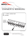
1
OWNER'S MANUAL
4 0 " L AW N A E R ATO R
MODEL:
SA-400BH
• Assembly
• Installation
• Operation
• Repair Parts
Original Instructions
For the latest product updates & setup tips:
Visit us on the web!
www.brinly.com
Important:
This manual contains information for the safety
of persons and property. Read it carefully before
assembly and operation of the equipment!
1008590BH-A
INTRODUCTION AND SAFETY
================================================================================================
CONGRATULATIONS on the purchase of your new Brinly-Hardy Aerator! Your
Aerator has been designed, engineered and manufactured to give you the best
possible dependability and performance.
Should you experience any problem you cannot easily remedy, please do not
hesitate to contact our knowledgeable customer service department toll-free at
1-877-728-8224. We have competent, well trained technicians to help you with the
assembly and use of your Aerator.
•
•
•
•
CUSTOMER RESPONSIBILITIES
Please read and retain this manual. The instructions will enable you to assemble and
maintain your Aerator properly.
•
•
Please carefully read and observe the SAFETY section of this manual.
Follow a regular schedule in maintaining and caring-for your Brinly-Hardy Aerator.
•
TABLE OF CONTENTS
•
SAFETY....................................................................................................................... 2
COMPONENT VIEW AND REFERENCE LIST ........................................................... 3
ASSEMBLY .............................................................................................................. 4-5
OPERATION................................................................................................................ 6
MAINTENANCE - STORAGE...................................................................................... 7
WARRANTY INFORMATION ...................................................................................... 8
•
•
SAFETY
========================================================
•
•
•
•
SAFETY LABELS AND NOTATION
•
This symbol will help to point out important safety precautions
throughout this manual. It means - ATTENTION! BECOME
ALERT! your safety is involved.
tow at speeds higher than the maximum recommended towing speed.
Towing speed should always be slow enough to maintain control. Travel slowly
over rough terrain. Avoid holes, rocks and roots. Slow down before turning.
Do not exceed the maximum towing capacity of your towing vehicle.
Do not tow this product behind a motor vehicle such as a car, truck or ATV.
Towing this product behind a ZTR (Zero Turn Radius) mower can affect the
stability of the mower and is not recommended.
Additionally, towing this product behind a ZTR mower is not recommended due
to the speed and sharp turning ability the ZTR. Damage to this product or ZTR
may result.
Know your towing vehicle controls and how to stop safely, READ YOUR
OWNER’S MANUAL before operating.
Check the towing vehicle brake action before you operate. Adjust or service
brakes as necessary.
Do not allow children to operate the towing vehicle. Do not allow adults to
operate the towing vehicle without proper instruction or without having read the
owner’s manual.
Always wear substantial footwear. Do not wear loose fitting clothing that can
get caught in moving parts.
Keep your eyes and mind on your towing vehicle, attachment and area being
covered. Do not let other interests distract you.
Stay alert for holes and other hidden hazards in the terrain.
The towing vehicle and attachment should be stopped and inspected for
damage after striking a foreign object. Any damage should be repaired before
restarting and operating the equipment.
Do not drive close to creeks, ditches and public highways.
Watch out for traffic when crossing near roadways.
Keep the towing vehicle and attachment in good operating condition and keep
safety devices in place.
Keep all parts in good condition and properly installed. Fix damaged parts
immediately. Replace worn or broken parts. Replace all worn or damaged
safety and instruction decals. Keep all nuts, bolts and screws tight.
Do not modify the attachment or safety devices. Unauthorized modifications
to the towing vehicle or attachment may impair its function or safety, and it will
void the warranty.
TOWING VEHICLE AND TOWING SAFELY
•
•
•
•
•
•
•
•
Read the safety operating precautions in your towing vehicle operator’s manual
for additional safety information.
Stopping distance increases with speed and weight of towed load. Travel
slowly and allow extra time and distance to stop. Total towed weight must not
exceed limits specified in towing vehicle operator’s manual.
Excessive towed load can cause loss of traction and loss of control on slopes.
Reduce towed weight when operating on slopes.
Use only approved hitches. Tow this attachment only with a towing vehicle that
has a hitch designed for towing. Do not connect this attachment except at the
approved hitch point.
Follow the towing vehicle manufacturer’s recommendations for weight limits for
towed equipment and towing on slopes. Use counterweights or wheel weights
as described in the towing vehicle operator’s manual.
Slow down before you turn and do not turn sharply. Use additional caution
when turning or operating under adverse surface conditions.
When reversing, carefully back-up straight to avoid jack-knifing. Do not allow
the towing vehicle’s wheels to contact the attachment drawbar. Damage could
result.
Do not shift to neutral and coast downhill.
PROTECT THOSE AROUND YOU
•
B-7063 (Not to Scale)
B-3922 (Not to Scale)
•
Keep children, bystanders and pets at a safe distance away while operating
this or any attachment.
Use care when reversing. Before you back up, look carefully behind for
bystanders.
Before you operate any feature of this attachment or towing vehicle, observe
your surroundings and look for bystanders.
The safety labels shown in this section are placed in important areas on your product
to draw attention to potential safety hazards.
•
On your product’s safety labels, the words DANGER, WARNING and CAUTION are
used with the safety-alert symbol. DANGER identifies the most serious hazards.
KEEP RIDERS OFF TOWED ATTACHMENT AND TOWING VEHICLE
The operator’s manual also explains any potential safety hazards whenever
necessary in special safety messages that are identified with the word, CAUTION,
and the safety-alert symbol.
GENERAL NOTES (OPERATION)
•
•
•
2.
Use this attachment for intended purpose only.
Before you operate any feature of this attachment or towing vehicle, observe
your surroundings and look for bystanders.
This attachment is intended for use in lawn care and home applications. Do not
tow behind a vehicle on a highway or in any high speed applications. Do not
1008590BH-A
•
•
Do not carry passengers.
Do not let anyone, especially children, ride in/on this attachment, the towing
vehicle or hitch bracket. Riders are subject to injury such as being struck by
foreign object and/or being thrown off during sudden starts, stops and turns.
Riders may also obstruct the operator’s view resulting in this attachment being
operated in an unsafe manner.
PARTS REFERENCE
================================================================================================
INSTALLATION
QUESTIONS?
MISSING PARTS?
Tools Required:
(1) Flat Head Screwdriver
(1) 7/16” Wrench
(1) Set of Pliers or Hammer
(1) Pair of Gloves.
REPLACEMENT PARTS?
STOP
DON’T GO BACK
TO THE STORE!
Please call our Customer Service
Department Toll-Free at
877.728.8224
or
www.customerservice
@brinly.com
10
11
10
6
5
7
1
14
14
13
13
12
19 15
16 11
4
21
3
20
1
13
13
17 15
12
13
2
13
17
14
14
12
17
15
14
12
9
13
12
15
19
9
8
REF
PART NO.
DESCRIPTION
QTY
REF
PART NO.
DESCRIPTION
1
1008490-10
2
1008491
3
End Panel
2
12
30M1000P
Hex Nut, 5/16"
10
Tine Shaft
1
13
40M1000P
Lock Washer, 5/16"
10
B-3593-10
Drawbar
1
14
45M1111P
Flat Washer, 5/16"
6
4
B-3922
Caution Aerator Decal
1
15
45M2121P
Flat Washer, 5/8"
8
5
1008489-10
Tray
1
16
B-3861
Hitch Pin, 1/2" X 2-1/2"
1
6
1008563
BH Logo Decal
1
17
B-6270
Square Bearing
2
7
B-7063
Pictorial Caution Label
1
18
D-146P
Hairpin Cotter, 1/8"
1
8
B-5423
Tine
10
19
F-577
E Ring, 5/8"
2
9
1008592
Bearing
20
20
R-821-10
Clevis
1
10
20M1012P
Round Head Screw, 5/16" X 3/4"
6
21
L-1744
Serial No Label
1
11
20M1016P
Round Head Screw, 5/16" X 1"
4
1008590BH-A
QTY
3.
ASSEMBLY
================================================================================================
Figure 1
1.
2.
12
12
Install Drawbar (3) to the Tray (5) using two 5/16" X
1" Round Head Screws (11), two 5/16" Lock Washers
(13), and two 5/16" Hex Nuts as shown in Figure 1.
3
Assemble the Clevis Drawbar (20) to the Drawbar (3)
using two 5/16" X 1" Round Head Screws (11), two
5/16" Lock Washers (13), and two 5/16" Hex Nuts
(12). See Figure 1.
13
5
13
NOTE: Install Clevis (20) in direction shown.
20
11
11
Figure 2
12
3
12
13
3.
Install the two End Panels (1) to the Tray (5) using six
5/16" X 3/4" Round Head Screws (10), six 5/16" Flat
Washers (14), six 5/16" Lock Washers, and six 5/16"
Hex Nuts (12). See Figure 2.
12
14
5
NOTE: Leave nuts loose in this step so that the
End Panels can be adjusted later.
13
14
10
10
Figure 3
19 15
4.
Fasten an E Ring (19) onto the Tine Shaft (2) and
place a Flat Washer (15) onto the Tine Shaft, see
Figure 3. Push the shaft through one end panel.
5.
Place a Square Bearing (17) and then a Flat Washer
(15) onto the Tine Shaft, see Figure 3.
4.
1008590BH-A
17 15
2
1
13
14
ASSEMBLY
================================================================================================
CAUTION: Gloves are required when handling
aerator tines. Tines have extremely sharp points.
Use caution when handling.
6.
Figure 4
15 17
Position the 10 Tines (8) and 20 Bearings (9) onto the Tine
Shaft as follows:
* Bearing (9), small end first
* Tine (8)
* Bearing (9), large end first
See Figure 4.
NOTE: Round projections on Bearings (9) must fit
into holes in Tines (8) and into two holes of opposite
Bearing.
7.
8
9
9
Place a Flat Washer (15) and then a Square Bearing (17)
onto the Tine Shaft between the last bearing and the End
Panel, and Push the Square Bearing into the hole on the
End Plate, see Figure 4.
Bearing (small end first)
Aerator Tine
Bearing (large end first)
CAUTION: Gloves are required when tightening
End Panel Bolts. Tines have extremely sharp
points. Use caution when working around them.
8.
Push the End Panels (1) toward the Tines (8) until there is no
free play along the Tine Shaft and tighten the nuts (A) on the
End Panels. See Figure 6, 6 nuts total.
Figure 5
15 19
NOTE: The Square Bearings must be completely
inserted into the End Panels before you tighten the nuts.
9.
Push the end of the Tine Shaft with the fastened E Ring
all the way towards the End Panel. Add as many Flat
Washers (15) to the opposite end of the shaft as necessary
to eliminate extra space. Fasten the remaining E ring on the
end of the Tine Shaft.
NOTE: Store extra Flat Washers in a safe location.
You may need them for maintenance of End Panel
Adjustment.
1
1
A
A
1008590BH-A
5.
OPERATION
================================================================================================
Figure 6
DEPTH / PENETRATION OF TINES
CAUTION: Avoid injury! Openings in Tray allow access to
Tines for cleaning and service. Excercise caution when
working around Tray openings and avoid placing body parts
into the openings.
Bagged weight material can fall through Tray Openings and be torn open or
damaged by the Tines. Use solid weight or close Tray Openings with wood panel or
by other suitable means.
16
17
Weight should be added to the tray after attaching to the towing vehicle.
Weight should be secured by rope, straps, or other suitable means to contain the
weight in the tray.
20
Maximum capacity of the Aerator Tray is 110 lbs.
CAUTION: Avoid injury! Make sure feet and hands are clear
of Tine Tips.
Tray Openings allow access to Tines for cleaning and service only and are not to be
used in any other application.
INSTALLING YOUR AERATOR
1.
2.
3.
Park towing vehicle safely and set the parking brake (see towing vehicle
operator’s manual).
Align Aerator Clevis (20) with towing machine hitch plate.
Install Hitch Pin (16) through Clevis (20) and towing machine hitch plate.
Secure Hitch Pin (16) with Hairpin Cotter (17).
REMOVING YOUR AERATOR
2.
3.
4.
5.
Park towing vehicle safely and set the parking brake (see towing vehicle
operator’s manual).
Unload weight from Aerator tray.
Remove Hairpin Cotter (17) and Hitch Pin (16).
Push Aerator away from the towing vehicle.
Install Hitch Pin (16) and Hairpin Cotter (17) for storage.
USAGE
CAUTION: Avoid injury! Avoid damage to tines. Do not
tow the aerator across concrete or asphalt driveways and
walkways.
CAUTION: Excessive towed load can cause loss of control
on slopes. Stopping distance increases with speed and the
weight of the towed load.
CAUTION: Total towed weight must not exceed combined
weight of towing vehicle, ballast and operator.
AERATOR WEIGHT
The following maximum loaded weight capacity is the weight of the Aerator plus the
maximum weight loaded into the Aerator Tray:
Model
Weight
SAT-400BH
Maximum Tray Weight
Maximum Towed Weight
6.
1008590BH-A
SPEED
The best operating speed is 3 mph or less.
Maximum operating speed is 5 mph.
FREQUENCY
CAUTION: Keep body parts away from under drawbar.
Do not attempt to disconnect Aerator from towing vehicle with
weight on the tray.
1.
Moderate soil moisture is important for proper tine penetration.
Extremely dry conditions will not permit tine penetration and may damage the tines.
Extremely wet conditions will cause full penetration of tines (up to tine bearings). This
condition will cut slots in the turf.
25 lbs (empty)
110 lbs
-------------------135 lbs
Lawn aeration is not accomplished in a single pass. It will normally take several
passes over the lawn. Alternating the direction by 90 degrees will improve the
aeration effect.
The Aerator may be used in an independent operation or may be used when mowing
your lawn.
MAINTENANCE-STORAGE
================================================================================================
MAINTENANCE
The key to years of trouble-free service is to keep your Aerator clean and dry.
After the first 30 minutes of use, check all fasteners for tightness.
Thereafter, periodically check all fasteners for tightness.
Tines are manufactured with galvanized steel to resist wear of abrasive soil. Striking
objects can cause Tines to curl or break. Contact Brinly-Hardy customer service
department to purchase replacement Tines.
Apply a light coat of oil on tines after use to prevent rust.
For rust appearing on painted surfaces, sand lightly and paint affected area with
enamel.
Periodically remove debris that builds up between Tines.
Apply lubricating oil at each tine bearing and axle bearing before use.
Figure 7
1
1
A
A
After use, the Tine and Tine Bearings may become loose on the Tine Shaft.
Should this occur, remove the looseness as follows (refer to Figure 7):
1.
2.
3.
Loosen the End Panel nuts (A).
Push the End Panels (1) toward the Tines until there is no free play along the
Tine Shaft.
Tighten the End Panel nuts (A).
NOTE: The Square Bearings must be completely inserted into the End Panels
before you tighten the End Panel nuts (A).
STORAGE
CAUTION: Avoid injury! The Aerator Tines are very sharp.
Care should be taken when choosing a storage location for
this product.
Store Aerator in low traffic aisle ways.
Store Aerator with Tine points facing the wall or ground.
Store Aerator on the ground or low to the ground.
Do not store Aerator hanging from the wall, ceiling or with Tine points facing outward.
Product packaging can be used to offer a protective area around the Tines.
Drawbar is a trip hazard. Avoid leaving Drawbar in aisle ways and walking paths.
1008590BH-A
7.
MANUFACTURER’S LIMITED WARRANTY
FOR
Pull Behind Accessories
The limited warranty set forth below is given by Brinly-Hardy
Company with respect to new merchandise purchased and used
in the United States, its possessions and territories.
Brinly-Hardy Company warrants the products listed below against
defects in material and workmanship, and will at its option, repair
or replace, free of charge, any part found to be defective in materials or workmanship. This limited warranty shall only apply if this
product has been assembled, operated, and maintained in accordance with the Operator’s manual furnished with the product, and
has not been subject to misuse, abuse, commercial use, neglect,
accident, improper maintenance, alteration, vandalism, theft, fire,
water, or damage because of other peril or natural disaster.
Normal Wear Parts or components thereof are subject to separate
terms as follows: All normal wear parts or component failures will
be covered on the product for a period of 90 days.
Parts found to be defective within the warranty period will be
replaced at our expense. Our obligation under this warranty is expressly limited to the replacement or repair, at our option, of parts
found to be defective in material and workmanship.
HOW TO OBTAIN SERVICE: Warranty parts replacements are
available, ONLY WITH PROOF OF PURCHASE, through our Pull
Behind Accessories Customer Service Department. Call 877-7288224.
This limited warranty does not provide coverage in the following
cases:
a) Routine maintenance items such as lubricants and filters.
b) Normal deterioration of the exterior finish due to use or
exposure.
c) Transportation and/or labor charges.
d) The warranty does not include rental use.
No implied warranty, including any implied warranty of merchantability of fitness for a particular purpose, applies after
the applicable period of express written warranty above as
to the part as identified below. No other express warranty
whether written or oral, except as mentioned above, given
by any person or entity, including a dealer or retailer, with
respect to any product, shall bind Brinly-Hardy Co. During
the period of the warranty, the exclusive remedy is repair or
replacement of the product as set forth above.
The provisions as set forth in this warranty provide the sole
and exclusive remedy arising from the sale. Brinly-Hardy
Co. shall not be liable for incidental or consequential loss
or damage including, without limitation, expenses incurred
for substitute or replacement lawn care services or for rental
expenses to temporarily replace a warranted product.
Some states do not allow the exclusion or limitation of incidental
or consequential damages, or limitations on how long an implied
warranty lasts, so the above exclusions or limitations may not apply to you.
During the warranty period, the exclusive remedy is replacement
of the part. In no event shall recovery of any kind be greater that
the amount of the purchase price of the product sold. Alteration
of safety features of the product shall void this warranty. You assume the risk and liability for loss, damage, or injury to you and
your property and/or to others and their property arising out of the
misuse or inability to use this product.
This limited warranty shall not extend to anyone other than the
original purchaser or to the person for whom it was purchased as
a gift.
HOW STATE LAW RELATES TO THIS WARRANTY: This limited
warranty gives you specific legal rights, and you may also have
other rights which vary from state to state.
IMPORTANT: The Warranty period stated below begins with the
PROOF OF PURCHASE. Without the proof of purchase, the Warranty period begins from the date of manufacture determined by
the serial number manufacturing date.
WARRANTY PERIOD:
The warranty period for the product shown in this manual is as
follows: Steel Frame Parts: consumer - 2 Years, commercial - 90
days. Tines are normal wear parts - 90 days.
Brinly-Hardy Company, 3230 Industrial Parkway, Jeffersonville, IN 47130 (877) 728-8224
8.
1008590BH-A