1
KE-430D
ELECTRONIC DIRECT DRIVE LOCKSTITCH
BAR TACKER
BE-438D
ELECTRONIC DIRECT DRIVE LOCKSTITCH
BUTTON SEWER
KE-430D, BE-438D
Thank you very much for buying a BROTHER sewing machine. Before using your new machine, please read the safety
instructions below and the explanations given in the instruction manual.
With industrial sewing machines, it is normal to carry out work while positioned directly in front of moving parts such as the
needle and thread take-up lever, and consequently there is always a danger of injury that can be caused by these parts.
Follow the instructions from training personnel and instructors regarding safe and correct operation before operating the
machine so that you will know how to use it correctly.
SAFETY INSTRUCTIONS
1. Safety indications and their meanings
This instruction manual and the indications and symbols that are used on the machine itself are provided in order to ensure
safe operation of this machine and to prevent accidents and injury to yourself or other people.
The meanings of these indications and symbols are given below.
Indications
instructions which follow this term indicate
DANGER The
instructions will result in death or serious injury.
situations where failure to follow the
The instructions which follow this term indicate situations where failure to follow the
could cause injury when using the machine or physical damage to equipment
CAUTION instructions
and surroundings.
Symbols
㨭㨭㨭㨭㨭㨭
This symbol ( ) indicates something that you should be careful of. The picture inside the triangle
indicates the nature of the caution that must be taken.
(For example, the symbol at left means “beware of injury”.)
㨭㨭㨭㨭㨭㨭
This symbol (
㨭㨭㨭㨭㨭㨭
This symbol (
) indicates something that you must do. The picture inside the circle indicates the
nature of the thing that must be done.
(For example, the symbol at left means “you must make the ground connection”.)
) indicates something that you must not do.
KE-430D, BE-438D
i
2. Notes on safety
DANGER
Wait at least 5 minutes after turning off the power switch and disconnecting the power cord from the wall outlet
before opening the face plate of the control box. Touching areas where high voltages are present can result in
severe injury.
CAUTION
Environmental requirements
Use the sewing machine in an area which is free from
sources of strong electrical noise such as electrical
line noise or static electric noise.
Sources of strong electrical noise may cause
problems with correct operation.
Any fluctuations in the power supply voltage should
be within ±10% of the rated voltage for the machine.
Voltage fluctuations which are greater than this may
cause problems with correct operation.
The power supply capacity should be greater than the
requirements for the sewing machine’s power
consumption.
Insufficient power supply capacity may cause
problems with correct operation.
The ambient temperature should be within the range
of 5°C to 35°C during use.
Temperatures which are lower or higher than this
may cause problems with correct operation.
The relative humidity should be within the range of
45% to 85% during use, and no dew formation should
occur in any devices.
Excessively dry or humid environments and dew
formation may cause problems with correct operation.
In the event of an electrical storm, turn off the power
and disconnect the power cord from the wall outlet.
Lightning may cause problems with correct operation.
Installation
Machine installation should only be carried out by a
qualified technician.
Contact your Brother dealer or a qualified electrician
for any electrical work that may need to be done.
The sewing machine weighs approximately 56 kg.
The installation should be carried out by two or more
people.
Do not connect the power cord until installation is
complete, otherwise the machine may operate if the
foot switch is depressed by mistake, which could
result in injury.
Hold the machine head with both hands when tilting it
back or returning it to its original position.
Furthermore, after tilting back the machine head, do
not push the face plate side or the pulley side from
above, as this could cause the machine head to
topple over, which may result in personal injury or
damage to the machine.
All cords should be secured at least 25 mm away
from any moving parts. Furthermore, do not
excessively bend the cords or secure them too firmly
with staples, otherwise there is the danger that fire or
electric shocks could occur.
Install the safety covers to the machine head and
motor.
If using a work table which has casters, the casters
should be secured in such a way so that they cannot
move.
Be sure to wear protective goggles and gloves when
handling the lubricating oil and grease, so that they
do not get into your eyes or onto your skin, otherwise
inflammation can result.
Furthermore, do not drink the oil or eat the grease
under any circumstances, as they can cause vomiting
and diarrhoea.
Keep the oil out of the reach of children.
Be sure to connect the ground. If the ground
connection is not secure, you run a high risk of
receiving a serious electric shock, and problems with
correct operation may also occur.
ii
KE-430D, BE-438D
CAUTION
Sewing
This sewing machine should only be used by
operators who have received the necessary training
in safe use beforehand.
If using a work table which has casters, the casters
should be secured in such a way so that they cannot
move.
The sewing machine should not be used for any
applications other than sewing.
Attach all safety devices before using the sewing
machine. If the machine is used without these
devices attached, injury may result.
Be sure to wear protective goggles when using the
machine.
If goggles are not worn, there is the danger that if a
needle breaks, parts of the broken needle may enter
your eyes and injury may result.
Turn off the power switch at the following times,
otherwise the machine may operate if the foot switch
is depressed by mistake, which could result in injury.
• When threading the needle
• When replacing the needle and bobbin
• When not using the machine and when leaving the
machine unattended
Do not touch any of the moving parts or press any
objects against the machine while sewing, as this
may result in personal injury or damage to the
machine.
If an error occurs in machine operation, or if abnormal
noises or smells are noticed, immediately turn off the
power switch. Then contact your nearest Brother
dealer or a qualified technician.
If the machine develops a problem, contact your
nearest Brother dealer or a qualified technician.
Cleaning
Turn off the power switch before carrying out
cleaning, otherwise the machine may operate if the
foot switch is depressed by mistake, which could
result in injury.
Be sure to wear protective goggles and gloves when
handling the lubricating oil and grease, so that they
do not get into your eyes or onto your skin, otherwise
inflammation can result.
Furthermore, do not drink the oil or eat the grease
under any circumstances, as they can cause vomiting
and diarrhoea.
Keep the oil out of the reach of children.
Maintenance and inspection
Maintenance and inspection of the sewing machine
should only be carried out by a qualified technician.
Ask your Brother dealer or a qualified electrician to
carry out any maintenance and inspection of the
electrical system.
Turn off the power switch and disconnect the power
cord from the wall outlet at the following times,
otherwise the machine may operate if the foot switch
is depressed by mistake, which could result in injury.
• When carrying out inspection, adjustment and
maintenance
• When replacing consumable parts such as the
rotary hook
If the power switch needs to be left on when carrying
out some adjustment, be extremely careful to observe
all safety precautions.
Hold the machine head with both hands when tilting it
back or returning it to its original position.
Furthermore, after tilting back the machine head, do
not push the face plate side or the pulley side from
above, as this could cause the machine head to
topple over, which may result in personal injury or
damage to the machine.
Use only the proper replacement parts as specified
by Brother.
If any safety devices have been removed, be
absolutely sure to re-install them to their original
positions and check that they operate correctly before
using the machine.
Any problems in machine operation which result from
unauthorized modifications to the machine will not be
covered by the warranty.
KE-430D, BE-438D
iii
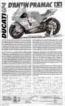
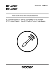
3. Warning labels
The following warning labels appear on the sewing machine.
Please follow the instructions on the labels at all times when using the machine. If the labels have been removed or are
difficult to read, please contact your nearest Brother dealer.
1
3
4
2
Be sure to connect the ground. If the ground
connection is not secure, you run a high risk of
receiving a serious electric shock, and problems
with correct operation may also occur.
Safety devices
Eye guard
Finger guard
Tension release solenoid cover
Thread take-up cover
Frame side cover
Back cover, etc.
Direction of operation
Thread take-up cover
Eye guard
Tension release
solenoid cover
Finger guard
Back cover
Frame side cover
4399Q
iv
4467Q
KE-430D, BE-438D
CONTENTS
1. NAMES OF MAJOR PARTS ................ 1
2. SPECIFICATIONS ................................ 2
2-1. Machine specifications ................................... 2
2-2. Program list (KE-430D) .................................. 3
2-3. Program list (BE-438D) .................................. 8
3. INSTALLATION .................................... 11
3-1. Table processing diagram .............................. 11
3-2. Installing the control box................................. 12
3-3. Installing the oil pan........................................ 12
3-4. Installing the machine head............................ 13
3-5. Installing the operation panel ......................... 14
3-6. Installing the treadle unit ................................ 14
3-7. Installing the cotton stand............................... 15
3-8. Installing the button tray (BE-438D) ............... 15
3-9. Installing the eye guard .................................. 15
3-10. Connecting the cords ................................... 16
3-11. Connecting the ground wire ......................... 18
3-12. Installing the back cover............................... 19
3-13. Lubrication .................................................... 20
3-14. Connecting the power cord .......................... 21
3-15. Starting up .................................................... 22
5. USING THE OPERATION PANEL
(BASIC OPERATIONS) ........................ 31
5-1. Name and function of each
operation panel item .......................................31
5-2. Setting the program number ...........................33
5-3. Setting the X-scale and Y-scale......................33
5-4. Setting the sewing speed................................33
5-5. Checking the sewing pattern (KE-430D) ........34
5-6. Checking the sewing pattern (BE-438D) ........35
5-7. Adjusting the work clamp / button clamp
lift amount........................................................36
6. USING THE OPERATION PANEL
(ADVANCED OEPRATIONS)............... 37
6-1. List of advanced functions ..............................37
6-2. Setting memory switches ................................38
6-3. List of memory switches .................................39
6-4. Using the lower thread counter.......................40
6-5. Using the production counter..........................41
6-6. Using user programs ......................................42
6-7. Using cycle programs .....................................45
6-8. Direct selection ...............................................48
6-9. Loading additional sewing data ......................48
4. PREPARATION BEFORE SEWING..... 23
7. SEWING ............................................... 49
4-1. Installing the needle........................................... 23
4-2. Threading the upper thread............................ 23
4-3. Winding the lower thread................................ 25
4-4. Installing the bobbin case............................... 26
4-5. Thread tension................................................ 26
4-5-1. Lower thread tension .......................... 26
4-5-2. Upper thread tension .......................... 27
4-6. Thread nipper device...................................... 28
4-7. Inserting the button (BE-438D)....................... 30
4-8. Adjusting the button clamp (BE-438D)........... 30
4-9. Installing the accessory spring (BE-438D) ..... 30
8. MAINTENANCE.................................... 50
8-1. Cleaning the rotary hook.................................50
8-2. Cleaning the control box air inlet ports ...........51
8-3. Draining the oil ................................................51
8-4. Cleaning the eye guard...................................51
8-5. Checking the needle .......................................51
8-6. Lubrication ......................................................51
8-7. Applying grease
(Work clamp: KE-430D) ..................................52
8-8. Applying grease
(When “GREASEUP” appears).......................52
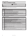
9. TABLE OF ERROR CODES................. 55
KE-430D, BE-438D
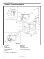
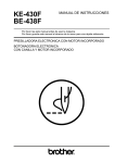
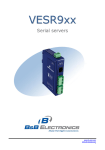
1. NAMES OF MAJOR PARTS
1. NAMES OF MAJOR PARTS
4401Q
(1) Power switch
(2) Control box
(3) CF slot
(4) Operation panel
(5) Foot switch
(6) Work clamp (KE-430D)
(7) Button clamp (BE-438D)
(8) Pulley
(9) Cotton stand
CF
1
TM
4400Q
Safety devices
(10) Finger guard
(11) Eye guard
(12) Thread take-up cover
(13) Back cover
(14) Frame side cover
(15) Tension release solenoid cover
is a trademark of SanDisk Corporation.
KE-430D, BE-438D
2. SPECIFICATIONS
2. SPECIFICATIONS
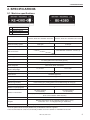
2-1. Machine specifications
1
2
7
F
Ordinary materials
Denim
Knitted materials
Foundation garments
KE-430D
Electronic direct drive lockstitch bar tacker
Stitch formation
Maximum sewing speed
Pattern size (X x Y)
BE-438D
Electronic direct drive lockstitch button sewer
Single needle lock stitch
3,200 rpm
2,700 rpm
40 x 30 mm max.
6.4 x 6.4 mm max.
Dimensions of buttons
that can be sewn
Feed mechanism
Outer diameter of button 8 - 30 mm (*1)
Y- intermittent feed mechanism (pulse-motor driven mechanism)
Stitch length
Number of stitches
Maximum stitch number
0.05 - 12.7 mm
Variable (Refer to "Program List" for details on the number of stitches
for sewing patterns that are already preset.)
210,000 stitches (including 200,000 stitches which can be added)
Work clamp lifter
Work clamp height
Button clamp height
Rotary hook
Pulse-motor driven mechanism
17 mm max.
13 mm max.
Shuttle hook (shuttle hook 2, optional)
Shuttle hook
Wiper device
Standard equipment
Thread trimmer device
Standard equipment
Thread nipper device
Standard equipment
Data storage method
Flash memory (Any sewing pattern can be added using CF card) (*2)
Number of user programs
50
Number of cycle programs
9
Number of stored data
89 sewing patterns
are set already
53 sewing patterns
are set already
(Up to 200 patterns can be added. Total number of stitches of stored data
which can be added is within 200,000.)
Motor
Weights
Power source
AC servo motor 550 W
Machine head: approx. 56 kg, Operation panel: approx. 0.6 kg
Control box: 14.2 – 16.2 kg (depending on destination)
Single-phase 100V / 220V, 3-phase 200V / 220V / 380V / 400V
400VA
*1 Use the optional button clamp B (S03634-101) for diameters of 20 mm or greater.
*2 The recommended CF cards are commercially-available ones from SanDisk or HAGIWARA SYS-COM.
KE-430D, BE-438D
2
2. SPECIFICATIONS
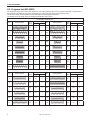
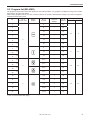
2-2. Program list (KE-430D)
The programs shown below have been preset into the sewing machine and can be selected according to specifications.
(Any program is available as long as the sewing pattern is within the work clamp and feed plate in size.)
Use the work clamp and feed plate that match the respective sewing pattern selected.
The sewing size is the length when the enlargement/reduction ratio is 100%.
For ordinary materials (-01)
No.
Sewing pattern
No. of
stitches
Tacking size (mm)
Length
Width
No.
Sewing pattern
No. of
stitches
Tacking size (mm)
Length
Width
1
42
16
2
65
43
16
2
4
31
16
2
66
32
16
2
5
29
10
2
67
30
10
2
8
21
7
2
68
22
7
2
13
35
10
2
69
36
10
2
15
42
10
2
70
43
10
2
20
28
7
2
71
29
7
2
21
35
7
2
72
36
7
2
64
30
16
2
89
90
24
3
For denim (-02)
No.
3
Sewing pattern
No. of
stitches
Tacking size (mm)
Length
Width
No.
Sewing pattern
No. of
stitches
Tacking size (mm)
Length
Width
2
42
20
3
18
56
24
3
3
35
20
3
19
64
24
3
6
30
16
3
62
42
20
3
14
35
16
3
63
35
20
3
16
43
16
3
78
43
20
3
17
42
24
3
79
36
20
3
KE-430D, BE-438D
2. SPECIFICATIONS
For denim (-02)
No.
No. of
stitches
Sewing pattern
Tacking size (mm)
Length
Width
No.
Sewing pattern
No. of
stitches
Tacking size (mm)
Length
Width
80
31
16
3
83
43
24
3
81
36
16
3
84
57
24
3
82
44
16
3
85
65
24
3
For Knitted materials (-07) and foundation garments (-0F)
No.
No. of
stitches
Sewing pattern
Tacking size (mm)
Length
Width
No.
Sewing pattern
No. of
stitches
Tacking size (mm)
Length
Width
7
28
8
2
73
29
8
2
9
21
7
2
74
22
7
2
22
14
7
2
75
15
7
2
31*
28
8
2
76*
29
8
2
32*
22
8
2
77*
23
8
2
33*
15
8
2
* The sewing start and sewing end are in the middle of the pattern.
Straight bar tacking
No.
10
Sewing pattern
Vertical zigzag stitching
No. of
stitches
21
Tacking size (mm)
Length
Width
10
No.
Sewing
pattern
No. of
stitches
Tacking size (mm)
Length
Width
0.3
11
28
10
0.3
12
28
20
0.3
23
35
25
0.3
24
42
25
0.3
25
45
25
0.3
KE-430D, BE-438D
44
46
9
15
45
70
9
25
4
2. SPECIFICATIONS
Vertical bar tacking
No.
5
Sewing pattern
No. of
stitches
Vertical straight bar tacking
Tacking size (mm)
Length
Width
No.
Sewing pattern
No. of
stitches
Tacking size (mm)
Length
Width
26
28
3
10
28
19
0.3
10
27
35
3
10
29
21
0.3
10
40
32
3
16
30
28
0.3
10
41
36
3
16
46
27
0.3
20
42
44
3
20
47
44
0.3
25
43
68
3
24
KE-430D, BE-438D
2. SPECIFICATIONS
Crescent bar tacking
No.
No. of
stitches
Sewing pattern
Tacking size (mm)
Length
Width
No.
Sewing pattern
No. of
stitches
Tacking size (mm)
Length
Width
34
35
12
7
37
57
7
12
35
58
12
7
38
53
7
10
36
57
7
12
39
53
7
10
Crossed tacking
Crossed stitching
No.
Sewing
pattern
No. of
stitches
Tacking size (mm)
Length
Width
No.
Sewing pattern
No. of
stitches
Tacking size (mm)
Length
Width
48
70
10
10
50
84
16
16
49
93
9.6
9.6
51
105
30
26
KE-430D, BE-438D
6
2. SPECIFICATIONS
L-pattern tacking
No.
Sewing pattern
No. of
stitches
Tacking size (mm)
Length
Width
No.
Sewing pattern
No. of
stitches
Tacking size (mm)
Length
Width
52
60
11.3
11.2
53
60
11.3
11.2
54
78
15.3
15.2
55
78
15.3
15.2
Circular stitching
No.
Sewing pattern
No. of
stitches
Tacking size (mm)
Length
Width
No.
Sewing pattern
No. of
stitches
Tacking size (mm)
Length
Width
56
106
9
9
59
104
10
10
57
116
9
9
60
114
10
10
58
127
9
9
61
124
10
10
For eyelet buttonhole
No.
Sewing pattern
No. of
stitches
Tacking size (mm)
Length
Width
86
21
6
2
87
28
6
2
88
35
6
2
If you want to sew a pattern other than standard patterns, you can create your original pattern using the PS-3000. Consult
with your local Brother sales Office for details.
Note when creating additional data (program nos. 200 - 999)
When sewing data with a small number of stitches (15 stitches or less) is sewn repeatedly (short cycle operation), the
upper shaft motor may overheat and the “E150” error code may be generated.
7
KE-430D, BE-438D
2. SPECIFICATIONS
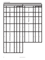
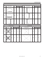
2-3. Program list (BE-438D)
The programs shown below have been preset into the sewing machine. Any program is available as long as the needle
drops down in the hole of the button.
When sewing programs that do not have crossover stitches, the thread is trimmed after sewing of one side is completed,
and then the other side is sewn.
No. of
threads
No. of
crossover
stitches
No. of
stitches
1
6
̆
12
2
8
̆
14
3
10
̆
16
4
12
̆
18
16
̆
22
20
̆
26
6
̆
12
10
̆
16
12
̆
18
5-5-5
̆
21
7-7-7
̆
27
5-5-5
̆
21
7-7-7
̆
27
10
6-6
1
19
11
8-8
1
23
8-8
3
25
13
10-10
1
27
27
12-12
1
31
No. of
button holes
No.
*1
5
2
*1
6
*2
7
*2
23
*2
8
*2
9
*2
24
Sewing
pattern
3
*2
25
*2
26
12
4
Sewing size (mm)
X
Y
3.4
0
0
3.4
2.6
2.4
3.4
3.4
*1 Check that the button hole diameter is 2 mm or greater before using the programs.
*2 Do not use the button lifter spring.
KE-430D, BE-438D
8
2. SPECIFICATIONS
No. of
threads
No. of
crossover
stitches
No. of
stitches
6-6
0
24
6-6
0
24
8-8
0
28
8-8
0
28
10-10
0
32
10-10
0
32
12-12
0
36
12-12
0
36
16
6-5
1
18
17
8-7
1
22
10-9
1
26
18
6-6
1
19
19
8-8
1
23
31
10-10
1
27
45
12-12
1
31
6-6
0
24
6-6
0
24
8-8
0
28
8-8
0
28
10-10
0
32
10-10
0
32
No. of
button holes
No.
*3
14
*4
36
*3
28
*4
37
*3
15
*4
38
*3
29
*4
39
4
30
*3
20
*4
40
*3
32
*4
41
*3
33
*4
42
Sewing
pattern
Sewing size (mm)
X
Y
3.4
3.4
*3 When sewing of one side is completed, the button clamp rises and the thread is trimmed. To finish sewing, press the foot
switch until sewing of the other side starts, or press the foot switch again after sewing of the other side is completed.
*4 When sewing of one side is completed, the thread will be trimmed without the button clamp rising, and then the other
side will be sewn.
9
KE-430D, BE-438D
2. SPECIFICATIONS
No. of
button holes
No.
Sewing
pattern
No. of
threads
No. of
crossover
stitches
No. of
stitches
6-6
1
19
10-10
1
27
6-6
0
24
*2
21
*2
34
*2 *3
22
*2 *4
6-6
0
24
10-10
0
32
10-10
0
32
46
6-6
1
19
47
8-8
1
23
48
10-10
1
27
49
12-12
1
31
43
*2 *3
35
Sewing size (mm)
X
Y
2.4
3.4
3.4
3.4
4
*2 *4
44
*2 Do not use the button lifter spring.
*3 When sewing of one side is completed, the button clamp rises and the thread is trimmed. To finish sewing, press the foot
switch until sewing of the other side starts, or press the foot switch again after sewing of the other side is completed.
*4 When sewing of one side is completed, the thread will be trimmed without the button clamp rising, and then the other
side will be sewn.
For shank button
No. of threads
No. of
stitches
50
6
12
51
8
14
52
10
16
53
12
18
No.
Sewing pattern
Sewing size (mm)
X
Y
3.4
0
Note when creating additional data (program nos. 200 - 999)
When sewing data with a small number of stitches (15 stitches or less) is sewn repeatedly (short cycle operation), the
upper shaft motor may overheat and the “E150” error code may be generated.
KE-430D, BE-438D
10
3. INSTALLATION
3. INSTALLATION
CAUTION
Machine installation should only be carried out by a
qualified technician.
Contact your Brother dealer or a qualified electrician
for any electrical work that may need to be done.
The sewing machine head weighs approximately 56
kg. The installation should be carried out by two or
more people.
Do not connect the power cord until installation is
complete, otherwise the machine may operate if the
foot switch is depressed by mistake, which could
result in injury.
All cords should be secured at least 25 mm away
from any moving parts. Furthermore, do not
excessively bend the cable or secure it too firmly
staples, otherwise there is the danger that fire or
electric shocks could occur.
Be sure to connect the ground. If the ground
connection is not secure, you run the risk of receiving
a serious electric shock, and problems with correct
operation may also occur.
Install the safety covers to the machine head and
motor.
Hold the machine head with both hands when tilting it
back or returning it to its original position.
Furthermore, after tilting back the machine head, do
not push the face plate side or the pulley side from
above, as this could cause the machine head to
topple over, which may result in personal injury or
damage to the machine.
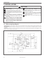
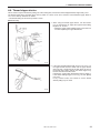
3-1. Table processing diagram
• The thickness of the table should be at least 40 mm, and it should be strong enough to bear the weight and vibration of the
sewing machine.
• If the distance A between the insides of the legs is less than 740 mm, move the control box installation position to the left (B
= 254 mm).
• Check that the control box is at least 10 mm away from the leg. If the control box and the leg are too close together, it may
result in incorrect sewing machine operation.
3625M
11
KE-430D, BE-438D
3. INSTALLATION㩷
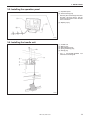
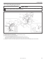
3-2. Installing the control box
Remove the eight screws (1), and then
remove the control box cover (2).
(3)
(4)
(5)
(6)
(7)
Control box
Bolts [4 pcs]
Spacers [4 pcs]
Plain washers [4 pcs]
Nuts [8 pcs]
* The recommended tightening
torque for the nuts (7) is
4.0±0.1N㨯m.
4403Q
(8) Power switch
(9) Wood screws [2 pcs]
(10) Staples [4 pcs]
Operator
4404Q
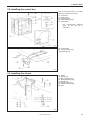
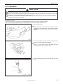
3-3. Installing the oil pan
(1)
(2)
(3)
(4)
(5)
(6)
(7)
(8)
Oil pan
Bolts [3 pcs]
Plain washers [3 pcs]
Spring washers [3 pcs]
Nuts [3 pcs]
Rubber caps [2 pcs]
Rubber cushion [2 pcs]
Oiler
4405Q
KE-430D, BE-438D
12
3. INSTALLATION㩷
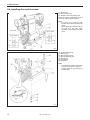
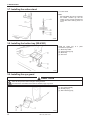
3-4. Installing the machine head
(1) Pins [2 pcs]
(2) Set screws [2 pcs]
(3) Rubber cushion assembly [2 pcs]
Place the machine head gently on top of
the oil pan and the rubber cushions.
Pulse motor
Approx. 20mm
Note:
• Be careful not to clamp any cords
between the machine head and the
oil pan.
• When holding the machine head, do
not hold it by the pulse motor,
otherwise it may damage the pulse
motor.
Approx. 20mm
4406Q
(4) Hinge holders [2 pcs]
(5) Bolts [4 pcs]
(6) Plain washers [4 pcs]
(7) Spring washers [4 pcs]
(8) Nuts [4 pcs]
(9) Head spring
(10) Head rest
Note:
• Check that the machine head switch
is turned on as shown in Figure 1.
• Tap the head rest (10) securely into
the table hole.
Figure㧝
4407Q
13
KE-430D, BE-438D
3. INSTALLATION㩷
3-5. Installing the operation panel
(1) Operation panel
(2) Wood screws [4 pcs]
* Pass the panel cord through the hole in
the table, and then insert it into the
control box through the hole in the side
of the control box.
(3) Staples [3 pcs]
4408Q
3-6. Installing the treadle unit
(1)
(2)
(3)
(4)
(5)
Treadle unit
Bolts [3 pcs]
Plain washers [3 pcs]
Spring washers [3 pcs]
Nuts [3 pcs]
* Use a commercially-available foot
switch and connecting rod.
4409Q
KE-430D, BE-438D
14
3. INSTALLATION㩷
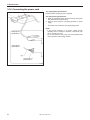
3-7. Installing the cotton stand
(1) Cotton stand
Note:
Securely tighten the nut (4) so that the
two rubber cushions (2) and the
washer (3) are securely clamped and
so that the cotton stand (1) does not
move.
3636M
3-8. Installing the button tray (BE-438D)
Install the button tray at a place
convenient for operation.
(1)
(2)
(3)
(4)
Button tray holder
Wood screws [2 pcs]
Button tray
Set screw
4410Q
3-9. Installing the eye guard
CAUTION
Attach all safety devices before using the sewing machine.
If the machine is used without these devices attached, injury may result.
(1) Eye guard assembly
(2) Screws [2 pcs]
(3) Plain washers [2 pcs]
4411Q
15
KE-430D, BE-438D
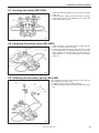
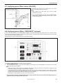
3. INSTALLATION㩷
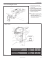
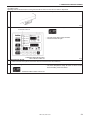
3-10. Connecting the cords
1. Gently tilt back the machine head.
2. Pass the cord bundle through the hole
in the work table.
3. Loosen the two screws (1), and then
open the cord presser plate (2) in the
direction of the white arrow and pass
the cord bundle through the opening.
4. Securely connect the connectors as
indicated in the table below.
Note:
• Check that the connector is facing
the correct way, and then insert it
firmly until it locks into place.
• Secure the cables with cable ties
and cord clamps, while being careful
not to pull on the connector.
4412Q
< Main P. C. board >
Lock the cord
clamp securely.
Connectors
4413Q
X pulse motor encoder [5-pin] White
Y pulse motor encoder [5-pin] Blue
Work clamp encoder [5-pin] Black
Foot switch [10-pin]
Operation panel [8-pin]
Machine head switch [3-pin]
Thread clamp sensor [6-pin]
KE-430D, BE-438D
Connection location on
main P. C. board
P2 (X-ENC)
P3 (Y-ENC)
P4 (P-ENC)
P5 (FOOT)
P6 (PANEL)
P8 (HEAD-SW)
P12 (TPK-SEN)
Cord clamps
(3)
(3)
(3)
(3)
(3)
(4)
(4), (5)
16
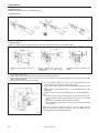
3. INSTALLATION㩷
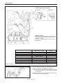
< Power supply motor P. C. board >
<Removal>
<Securing>
Press
the tab.
< PMD P. C. board >
The layout for the connector may differ from that
shown in the illustration depending on the version of
the PMD P. C. board.
Connect to connectors with the same color (e.g.
black to black).
Connectors
Machine head memory [7-pin]
Upper shaft motor [3-pin]
Synchronizer [14-pin]
Connectors
Work clamp pulse motor [4-pin] Black
Thread clamp pulse motor [6-pin]
Thread trimmer solenoid [6-pin]
Tension release solenoid [4-pin]
Y pulse motor [4-pin] Blue
X pulse motor [4-pin] White
Connection location on power
supply motor P. C. board
P3 (HEAD-M)
P4 (UVW)
P5 (SYNC)
Connection location on
PMD P. C. board
P3 (PPM)
P4 (BT-PICK)
P6 (SOL1)
P7 (SOL2)
P8 (YPM)
P10 (XPM)
Cord clamps /
Cable ties
(4)
(6)
(6), (7)
Note: Route the X, Y and work clamp pulse motor harnesses so that they do not touch the PMD P.C. board.
Cable ties
(6), (7)
(6), (7)
(6), (7)
(6), (7)
(6), (7)
(6), (7)
4113M
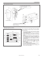
5. Close the cord presser plate (2) in the direction of the white
arrow, and secure it by tightening the two screws (1).
Note: Close the cord presser plate (2) securely so that no
foreign objects, insects or small animals can get inside
the control box.
6. Check that the cords do not get pulled, and then gently return
the machine head to its original position.
4415Q
17
KE-430D, BE-438D
3. INSTALLATION㩷
3-11. Connecting the ground wire
CAUTION
Be sure to connect the ground. If the ground connection is not secure, you run the risk of receiving a serious electric
shock, and problems with correct operation may also occur.
4416Q
(1)
(2)
(3)
(4)
Ground wire from upper shaft motor harness
Ground wire from the machine head
Ground wires from X, Y and work clamp encoder harnesses (3 wires)
Ground wire from operation panel harness
* The recommended tightening torque for the ground screws is 1.0±0.1 N㨯m.
Note: Make sure that the ground connections are secure in order to ensure safety.
(5) Tighten the control box cover with the eight screws. Check that the cords are not clamped by the cover at this time.
KE-430D, BE-438D
18
3. INSTALLATION㩷
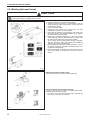
3-12. Installing the back cover
(1) Back cover
(2) Screws [4 pcs]
Note:
Be careful not to clamp the cords
when installing the back cover (1).
4417Q
19
KE-430D, BE-438D
3. INSTALLATION㩷
3-13. Lubrication
CAUTION
Do not connect the power cord until lubrication has been completed, otherwise the machine may operate if the foot switch
is depressed by mistake, which could result in injury.
Be sure to wear protective goggles and gloves when handling the lubricating oil and grease, so that they do not get into
your eyes or onto your skin, otherwise inflammation can result.
Furthermore, do not drink the oil or eat the grease under any circumstances, as they can cause vomiting and diarrhoea.
Keep the oil out of the reach of children.
The sewing machine should always be lubricated and the oil supply replenished before it is used for the first time, and also after
long periods of non-use.
Use only the lubricating oil <NIPPON OIL CORPORATION Sewing Lube 10N; VG10> specified by Brother.
* If this type of lubricating oil is difficult to obtain, the recommended oil to use is <Exxon Mobil Essotex SM10; VG10>.
1. Fill the oil tank with oil.
Note:
Fill the machine with oil when the oil level is down to about
one-third full in the oil sight glass. If the oil drops below this
level, there is the danger that the machine may seize during
operation.
4418Q
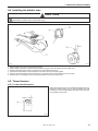
2. Pour oil in through the two holes (1) of the shuttle race base
assembly so that the felt is lightly moistened.
Note:
If there is no more oil on the felt of the shuttle race base
assembly, problems with sewing may result.
4419Q
3. If using the liquid cooling tank (2), fill it with silicon oil (100
mm2/s).
4537Q
KE-430D, BE-438D
20
3. INSTALLATION㩷
3-14. Connecting the power cord
<For single-phase specifications>
Insert the power cord plug (1) into a wall outlet.
<For three-phase specifications>
1. Attach an appropriate plug to the power cord (2). (The green
and yellow wire is the ground wire.)
2. Insert the power plug into a properly-grounded AC power
supply.
*
The inside of the control box uses single-phase power.
NOTE:
If the ground connection is not secure, electric shocks,
operating errors or damage to electronic components such
as P.C. boards may occur.
Do not use extension cords. They may cause problems with
correct operation of the sewing machine.
<Single-phase
specifications>
<Three-phase
specifications>
Green/yellow wire
(Ground wire)
4114M
21
KE-430D, BE-438D
3. INSTALLATION㩷
3-15. Starting up
Before starting home position detection, check that the
needle bar is at its highest position.
Turn the machine pulley so that the index mark (1) on the pulley
is inside the mark (2) on the back cover.
Note:
If the machine is started while the index mark (1) is not
inside the mark (2), error code "E110" will be displayed. (At
this time, the error will be cleared if you turn the machine
pulley to set the needle to the needle up stop position.)
4420Q
1. Turn on the power switch.
The POWER indicator (3) will illuminate, and the model
name will appear in the program No. display (4) and the
specifications will appear in the menu display (5).
4421Q
Specifications
Ordinary materials
Denim
Knitted materials
Foundation garments
[
[
[
[
- 01]
- 02]
- 07]
- 0F]
After this, the program number will flash in the program No.
display (4).
4422Q
2. Depress the foot switch (6) to the 2nd step.
The feed mechanism will move to the home position and the
work clamp / button clamp will rise.
2nd step
4423Q
KE-430D, BE-438D
22
4. PREPARATION BEFORE SEWING
4. PREPARATION BEFORE SEWING
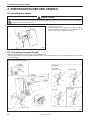
4-1. Installing the needle
CAUTION
Turn off the power switch before installing the needle, otherwise the machine may operate if the foot switch is depressed
by mistake, which could result in injury.
1. Loosen the set screw (1).
2. Insert the needle (2) in a straight line as far as it will go,
making sure that the long groove on the needle is at the
front, and then securely tighten the screw (1).
4424Q
4-2. Threading the upper thread
Thread the upper thread correctly as shown in the illustration below.
* When using threading mode for threading, the tension discs (1) will open so that the thread can be threaded more easily. (Refer
to following page.)
[When using the liquid cooling tank]
[Two holes]
Spun rayon yarn
Synthetic thread
[One hole]
Approx. 40mm
4425Q
23
4426Q
KE-430D, BE-438D
4. PREPARATION BEFORE SEWING㩷
<Threading mode>
Threading mode is safe because the sewing machine will not start even when the foot switch is depressed.
Turn on the power switch.
1
4421Q
Press the THREAD/CLAMP key.
2
All indicators switch off
• The work clamp /button clamp will lower.
• The tension discs will open.
THREAD/CLAMP indicator lights
Menu indicators switch off
4427Q
3
Threading the thread.
• When 5 minutes have passed, the buzzer will sound and the tension discs will close.
4
Ending threading mode
Press the THREAD/CLAMP key.
• The work clamp/button clamp will return to where it was
before threading mode was started.
THREAD/CLAMP indicator switches off
KE-430D, BE-438D
24
4. PREPARATION BEFORE SEWING㩷
4-3. Winding the lower thread
CAUTION
Do not touch any of the moving parts or press any objects against the machine while winding the lower thread, as this may
result in personal injury or damage to the machine.
4429Q
1. Place the bobbin onto the bobbin winder shaft (1).
2. Thread the thread as shown in the illustration, wind the
thread around the bobbin several times, and then press the
bobbin presser arm(2).
3. Turn on the power switch.
4. Depress the foot switch to the second step. The feed
mechanism will move to the home position.
5. Check that the needle is not touching the work clamp, and
then while pressing the TENSION WIND key (3), depress
the foot switch to the second step.
6. Release the TENSION WIND key (3) after the machine
starts operating, and keep depressing the foot switch until
the lower thread stops being wound onto the bobbin.
(If you release the foot switch before winding is complete,
and then depress it again while pressing the TENSION/
WIND key (3), winding will start again.)
7. Once winding of the set amount of lower thread (80 - 90% of
the bobbin capacity) is completed, the bobbin presser arm
(2) will return automatically.
8. Remove the bobbin, hook the thread onto the knife (4), and
then pull the bobbin in the direction of the arrow to cut the
thread.
4431Q
4430Q
4432Q
Adjusting the bobbin winding amount
Loosen the screw (5) and move the bobbin presser (6).
Case 㧭
If the thread winds onto the bobbin unevenly
Loosen the set screw (7) and move the bobbin wider tension
assembly (8) up and down to adjust.
* For case A, move the bobbin winder tension assembly (8)
down, and for case B, move it upward.
Case 㧮
4471Q
25
KE-430D, BE-438D
4. PREPARATION BEFORE SEWING㩷
4-4. Installing the bobbin case
CAUTION
Turn off the power switch before installing the bobbin case, otherwise the machine may operate if the foot switch is
depressed by mistake, which could result in injury.
2534Q
30mm
2535Q
4433Q
1.
2.
3.
4.
5.
6.
Pull the shuttle race cover (1) downward to open it.
While holding the bobbin so that the thread winds to the right, insert the bobbin into the bobbin case.
Pass the thread through the slot (2) and pull it out from the thread hole (3).
Check that the bobbin turns in the direction of the arrow when the thread is pulled.
Pass the thread through the lever thread hole (4), and then pull out approximately 30 mm of thread.
Hold the latch on the bobbin case and insert the bobbin case into the rotary hook.
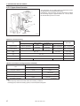
4-5. Thread tension
4-5-1. Lower thread tension
Adjust the thread tension to the weakest possible tension by
turning the thread tension nut (1) until the bobbin case will
not drop by its own weight while the thread end coming out
of the bobbin case is held.
weaker
stronger
2536Q
KE-430D, BE-438D
26
4. PREPARATION BEFORE SEWING㩷
4-5-2. Upper thread tension
Turn the tension nut (1) (main tension) to adjust the tension
as appropriate for the material being sewn.
Furthermore, turn the tension nut (2) (sub-tension) to adjust
the remaining length of upper thread to 35 - 40 mm, when
the thread take-up lever is not used.
Stronger
Weaker
Stronger
Weaker
4434Q
[Reference thread tension]
KE-430D
Use
Ordinary materials (-01)
Upper thread
#50 or equivalent
Lower thread
#60 or equivalent
Upper thread tension
(N)
Lower thread tension
(N)
Knitted materials
(-07)
#60 or
equivalent
#80 or
equivalent
0.8 - 1.2
Pre-tension (N)
Needle
Foundation
garments (-0F)
#60 or
equivalent
#60 or
equivalent
DP x 5 #14
#30 or equivalent
#60 or equivalent
#50 or equivalent
#60 or equivalent
1.6 - 2.0
1.0 - 1.8
0.2 - 0.3
0.2 - 0.4
0.05 - 0.3
0.1 - 0.4
DP x 5 #9
DP x 17NY #19
[Guide to maximum sewing speed for KE-430D]
Max. sewing speed (rpm)
Use
Standard hook
Large hook
8 layers of denim
3,200
2,500
12 layers of denim
2,700
Ordinary materials
2,700
Knitted materials
Foundation garments
2,500
2,500
Note:
The thread may break due to heat under some sewing conditions.
If this happens, reduce the sewing speed, or use the liquid cooling tank.
27
BE-438D
Denim (-02)
KE-430D, BE-438D
DP x 17NY #12
4. PREPARATION BEFORE SEWING㩷
4-6. Thread nipper device
This is used to stop the thread from pulling out at the sewing start, and at times when skipped stitches might easily occur.
The thread nipper device operates when memory switch no. 500 is set to "ON". However, some limitations apply. Refer to
"6-3. List of memory switches" for details.
* The default setting for this memory switch is "OFF".
[Notes on use]
1. When using the thread nipper device, turn the tension
nut (1) (sub-tension) to adjust the upper thread trailing
length to 35 - 38 mm.
* Adjust the upper thread trailing length to less than 40
mm after replacing the upper thread also.
4473Q
2. If the upper thread trailing length is 40 mm or more, or if
the upper thread tension is weak and the upper thread
does not form a good seam at the first stitch, the end of
the thread that is being held by the thread nipper may
become wound around the seam.
Furthermore, if using thick thread that is #30 or higher or
if the thread trailing length is too long, an error [E691]
may occur.
In any of these cases, use scissors to cut the thread
without pulling it up too hard.
4475Q
KE-430D, BE-438D
28
4. PREPARATION BEFORE SEWING㩷
3. For sewing patterns with a short bar tack length (10 mm
or less), the end of the thread that is being held by the
thread nipper may poke out from the seam on the
underside of the material. It is recommended that you
change the thread nipper setting to "OFF" for patterns
such as these.
(Front)
4. If error [E690] or [E691] frequently occurs, remove the
needle plate and remove any thread scraps from
underneath the needle plate.
(Back)
Upper thread
4487Q
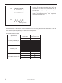
5. With the KE-430D, the lower thread may poke out from the underside of the material on the 2nd stitch for some types of
material and thread. If this happens, it is recommended that you use sewing patterns that are designed for use with the
thread nipper device.
Refer to "2-2. Program list (KE-430D)" for details of the sewing patterns.
<Program No. Reference Table>
Specifications
For ordinary materials (-01)
For denim (-02)
For knitted materials (-07)
For foundation garments (-0F)
29
Standard
program No.
1
4
5
8
13
15
20
21
2
3
6
14
16
17
18
19
7
9
22
31
32
Program No. for
thread nipper device
65
66
67
68
69
70
71
72
78
79
80
81
82
83
84
85
73
74
75
76
77
KE-430D, BE-438D
4. PREPARATION BEFORE SEWING㩷
4-7. Inserting the button (BE-438D)
1. Press the button clamp plate cam (1) to open the button
holder (2).
2. Insert the button, making sure that the button is facing
the directing shown in the illustration, then release the
button clamp plate cam (1).
4115M
4-8. Adjusting the button clamp (BE-438D)
1. Insert the button in the button clamp. Confirm that the
button is securely held by the clamp.
2. Loosen the shoulder screw (1), while the button is held
by the clamp. Move the adjusting plate (2) so that the
space between the adjusting plate (2) and screw (3) is
approximately 0.5 - 1.0 mm, then tighten the shoulder
screw (1).
0.5 - 1.0mm
2660Q
4-9. Installing the accessory spring (BE-438D)
If you would like the button to be raised up more after it is
sewn, install the accessory spring.
1. Install the spring support (1) with the bolt (2).
2. Install the spring (3) with the washer (4) and the screw
(5).
2661Q
KE-430D, BE-438D
30
5. USING THE OPERATION PANEL (BASIC OPERATIONS)
5. USING THE OPERATION PANEL (BASIC OPERATIONS)
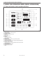
5-1. Name and function of each operation panel item
4435Q
(1) Power indicator
Illuminates when the power is turned on.
(2) CAUTION indicator
Illuminates when an error occurs.
(3) RESET key
Used to reset errors.
(4) TEST key
Used to start test mode.
(5) TEST indicator
Illuminates when the TEST key (4) has been pressed.
(6) THREAD/CLAMP key
Used to start threading mode or work clamp height setting mode.
(7) THREAD/CLAMP indicator
Illuminates when the THREAD/CLAMP key (6) has been pressed.
(8) TENSION/WIND key
Used to wind the lower thread.
(9) TENSION/WIND indicator
Spare
31
KE-430D, BE-438D
5. USING THE OPERATION PANEL (BASIC OPERATIONS)㩷
(10) X-SCALE indicator
Illuminates when the SELECT key (15) is pressed to shown the X-scale setting.
(11) Y-SCALE indicator
Illuminates when the SELECT key (15) is pressed to shown the Y-scale setting.
(12) SPEED indicator
Illuminates when the SELECT key (15) is pressed to shown the sewing speed setting.
(13) COUNTER indicator
Illuminates when the SELECT key (15) is pressed to shown the lower thread or production counter setting.
(14) SPLIT No. indicator
Illuminates when the SELECT key (15) is pressed to show the split setting when split data (for specifying a pause while the
program is running) exists.
(15) SELECT key
Used to select a menu (X-scale, Y-scale, sewing speed and counter).
(16) Menu display
Displays information such as menu setting values, memory switch settings and error codes.
(17) Setting keys
Used to change the value which is displayed in the menu display (16).
(18) PROGRAM No. display
Displays information such as program numbers.
(19) Setting keys
Used to change the value which is displayed in the PROGRAM No. display (18).
(20) CF media indicator
Illuminates when a CF card (external media) is inserted.
(21) FD media indicator
Spare
(22) Function keys [F1, F2, F3, F4]
Used to select user programs and to set and select cycle programs.
(23) R/W key
Used to read data from and write data to external media.
CFTM is a trademark of SanDisk Corporation.
KE-430D, BE-438D
32
5. USING THE OPERATION PANEL (BASIC OPERATIONS)㩷
5-2. Setting the program number
The program number is set to 0 (feed home position check)
at the time of shipment from the factory.
2nd step
4436Q
1. Press the
or
key (1) to select the program
number.
• The program number will flash in the PROGRAM No.
display (2).
2. Depress the foot switch to the 2nd step.
• The feed mechanism will move to the home position
and the program number will be accepted.
• The program number will stop flashing and illuminate
steadily.
Note:
Once the setting is complete, be sure to carry out the
steps in "5-5./5-6. Checking the sewing pattern" to check
that the needle drop position is correct.
5-3. Setting the X-scale and Y-scale
The scales are set to 100 (%) at the time of shipment from
the factory.
1. Press the SELECT key (1) so that the X-SCALE
indicator (2) (for X-scale setting) or the Y-SCALE
indicator (3) (for Y-scale setting) is illuminated.
• The setting value (%) will display in the menu display
(4).
* When memory switch no. 402 is set to "ON", the
settings will be displayed in units of mm.
2. Press the
or
key (5) to set the scale (20 - 200).
• The program number will flash in the PROGRAM No.
display (6).
3. Depress the foot switch to the 2nd step.
• The feed mechanism will move to the home position
and the scale will be accepted.
• The program number will stop flashing and illuminate
steadily.
Note:
Once the setting is complete, be sure to carry out the
steps in "5-5./5-6. Checking the sewing pattern" to check
that the needle drop position is correct.
2nd step
4437Q
5-4. Setting the sewing speed
The sewing speed is set to 2000 (rpm) at the time of
shipment from the factory.
1. Press the SELECT key (1) until the SPEED indicator (2)
illuminates.
• The setting value (rpm) will display in the menu
display (3).
2. Press the
or
key (4) to set the sewing speed.
(Sewing speed setting values
KE-430D: 400 - 3200,
BE-438D: 400 - 2700)
4438Q
33
KE-430D, BE-438D
5. USING THE OPERATION PANEL (BASIC OPERATIONS)㩷
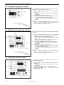
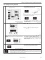
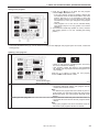
5-5. Checking the sewing pattern (KE-430D)
Use test feed mode to check the needle movement with only the feed mechanism operating.
Check that the needle hole does not come out from the frame of the work clamp.
1
Press the TEST key.
TEST indicator lights
2
3
Select the program number to be checked, and then set
the X-scale and the Y-scale.
• The program number will flash.
Depress the foot switch to the 2nd step.
• The feed mechanism will move to the home position
and the program number will stop flashing and
illuminate steadily.
2nd step
Program number flashing lit
Starting continuous test feed mode
1st step
2nd step
4440Q
4441Q
Depress the foot switch to the 2nd step and then release
it.
• Feed mechanism starts moving continuously one stitch
at a time.
[Fast-forward test mode]
If you depress the foot switch to the 1st step while the
feed mechanism is moving, the feeding speed will
become faster while the foot switch is being depressed.
4441Q
4441Q
If you would like sewing to start while test feeding is in
progress, press the TEST key to switch off the TEST
indicator.
When you depress the foot switch to the 2nd step,
sewing will start.
[Sewing standby mode]
2nd step
TEST indicator switches off
• If you press the
key when in this mode, the feed will move forward
key, the feed will move backward one
one stitch, and if you press the
stitch. (The feed will move quicker if you keep the key pressed down.)
4443Q
• If you would like to start test feed once more, press the TEST key.
TEST indicator lights
4
If test feeding continues to the final stitch, it will then
stop.
Press the TEST key.
TEST indicator switches off
5
1st step
Depress the foot switch to the 1st step.
The work clamp will rise and the preparation for sewing
will be completed.
4441Q
KE-430D, BE-438D
34
5. USING THE OPERATION PANEL (BASIC OPERATIONS)㩷
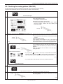
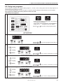
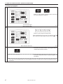
5-6. Checking the sewing pattern (BE-438D)
Use test feed mode to check the needle movement with only the feed mechanism operating.
1
Press the TEST key.
TEST indicator lights
2
3
4
Select the program number to be checked, and then set
the X-scale and the Y-scale.
• The program number will flash.
Depress the foot switch to the 2nd step.
• The feed mechanism will move to the home position
and the program number will stop flashing and
illuminate steadily.
2nd step
4440Q
Program number flashing lit
Set the button. (Refer to “4-7. Inserting the button”.)
Starting single-stitch test feed mode
4441Q
Depress the foot switch to the 2nd step and then release
it.
• The feed mechanism will move by one stitch only.
1st step
2nd step
After this, the feed mechanism will move forward by one stitch each time you depress the foot switch to the 1st step.
Turn the pulley by hand each time the mechanism moves by one stitch, and check whether the needle drops into the
hole of the button without touching the button. (If you turn the machine pulley one full rotation in the direction of
sewing machine operation at this time, the feed mechanism will move forward by one stitch when the needle bar is
near the needle up position.)
In addition, if you depress the foot switch to the 2nd step again, the feed mechanism will start moving continuously
one stitch at a time.
4441Q
4441Q
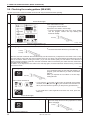
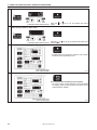
[Sewing standby mode]
If you would like sewing to start while test feeding is in
progress, press the TEST key to switch off the TEST
indicator.
When you depress the foot switch to the 2nd step,
2nd step
sewing will start.
TEST indicator switches off
• If you press the
key when in this mode, the feed will move forward
one stitch, and if you press the
key, the feed will move backward one
stitch. (The feed will move quicker if you keep the key pressed down.)
4443Q
• If you would like to start single-stitch test feed once more, press the
TEST key.
TEST indicator lights
5
Ending test feed mode
Press the TEST key.
6
Depress the foot switch to the 1st step.
The work clamp will rise and the preparation for sewing
will be completed.
1st step
4441Q
TEST indicator switches off
35
KE-430D, BE-438D
5. USING THE OPERATION PANEL (BASIC OPERATIONS)㩷
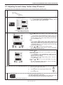
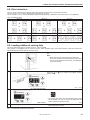
5-7. Adjusting the work clamp / button clamp lift amount
The setting for the work clamp/button clamp lift amount can be changed using the operation panel.
1
Carry out home position detection.
4441Q
2
Press the THREAD/CLAMP key.
The sewing machine will switch to threading mode.
• “
1” will appear in the PROGRAM No. display, and the
work clamp / button clamp will be lowered.
All indicators switch off
THREAD/CLAMP indicator lights
Menu indicators switch off
3
Press the
key.
The sewing machine will switch to work clamp height setting
mode.
• " 2" will appear in the PROGRAM No. display and the work
clamp/button clamp will rise to the setting value that appears in
the menu display. (Work clamp height setting values KE-430D:
10 - 17, BE-438D: 6 - 13)
Note:
If you press the
key before home position detection has
been carried out, the sewing machine will not switch to work
clamp height setting mode. (The buzzer will sound.) Press the
THREAD/CLAMP key to end setting mode and then repeat
the procedure from step 1.
Press the
or
key to set the work clamp height.
• The work clamp/button clamp will rise or drop to the height of
the new value that has been set.
4446Q
When memory switch no.003 is "ON"
4447Q
<Switching modes>
Press the
key.
The sewing machine will switch to intermediate work clamp
height setting mode.
• " 3" will appear in the PROGRAM No. display and the
work clamp/button clamp will move to the setting value that
appears in the menu display.
(Intermediate work clamp height setting values KE-430D:
1 - 17, BE-438D: 1 - 13)
Press the
or
key to set the intermediate work clamp
height.
• The work clamp/button clamp will rise or drop to the height
of the new value that has been set.
[
([
[
4
4445Q
Ending setting mode
2] Work clamp height setting mode
3] Intermediate work clamp height setting mode)
1] Threading mode
4448Q
Press the THREAD/CLAMP key.
• The setting values will be memorized.
• The work clamp/button clamp will return to the status that it was at
before the sewing machine was switched to setting mode.
THREAD/CLAMP indicator switches off
KE-430D, BE-438D
36
6. USING THE OPERATION PANEL (ADVANCED OPERATIONS)㩷
6. USING THE OPERATION PANEL (ADVANCED OPERATIONS)
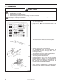
6-1. List of advanced functions
While holding down the TEST key, press the corresponding combination key.
4488Q
1
Memory switch setting mode
Refer to “6-2. Setting memory switches”.
4489Q
2
Lower thread counter setting mode
Refer to “6-4. Using the lower thread counter”.
4490Q
3
Production counter setting mode
Refer to “6-5. Using the production counter”.
4491Q
4
When the SPEED indicator lights
Production counter temporary display function
Refer to “6-5. Using the production counter”.
User program setting mode
Refer to “6-6. Using user programs”.
4492Q
5
37
4493Q
KE-430D, BE-438D
6. USING THE OPERATION PANEL (ADVANCED OPERATIONS)㩷
6-2. Setting memory switches
1
While pressing the SELECT key, turn on the power switch.
* Keep pressing the SELECT key until the model name is
displayed and the buzzer beeps once.
All indicators switch off
Or
With the power turned on, press the TEST key and the
TENSION/WIND key simultaneously.
Menu indicators switch off
TEST indicator lights
2
• The memory switch number will appear in the
PROGRAM No. display, and its setting value will appear
in the menu display.
4449Q
Press the
number.
Press the
or
or
4421Q
key to select the memory switch
key to change the setting value.
4451Q
If you would like to display only the numbers of
memory switches that have been changed from default
settings
While pressing the SELECT key, press the
or
key.
• The numbers of memory switches that have been
changed from default settings will appear in order.
• If no memory switches have been changed from their
default settings, the display will not change and the
buzzer will beep twice.
4452Q
3
Ending setting mode
Press the TEST key.
• The changes will be memorized and the sewing machine
will switch to home position detection standby.
TEST indicator switches off
• If you would like to return the setting for a single memory switch to the default setting, press the RESET key
while the number for that memory switch is displayed.
• To return the settings for all memory switches to the default settings, keep pressing the RESET key for two
or more seconds until the buzzer makes a long beep.
KE-430D, BE-438D
38
6. USING THE OPERATION PANEL (ADVANCED OPERATIONS)㩷
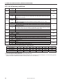
6-3. List of memory switches
No.
001
003
100
200
300
400
401
402
500
Setting
Setting items
range
Work clamp/button clamp lift timing when sewing is complete
OFF
Lifts at the final stitch position.
ON
Lifts after moving to the home position.
2-step work clamp
OFF
Disable
Stops at intermediate work clamp height setting mode when foot switch is
ON
depressed to 1st step, and then drops fully and sewing starts when foot switch is
depressed to 2nd step.
Sewing start speed
The sewing speed for the first 1 - 5 stitches is set by memory switch nos. 151 OFF
155.
(Refer to the Service Manual for details of memory switch nos. 151 - 155.)
ON
Refer to (*1) below.
Single-stitch test feed
Test feed starts when the foot switch is depressed, and it continues automatically
OFF
until the final stitch.
Test feeding is carried out stitch by stitch when the foot switch is depressed.
ON
In addition, when the test indicator is illuminated, test feeding will move forward
one stitch at a time when the machine pulley is turned by hand.
Production counter display
OFF
Lower thread counter display
ON
Production counter display
User programs
OFF
Disable
ON
User program mode is enabled.
Cycle programs
OFF
Disable
ON
When sewing user programs, the set programs are sewn in numeric order.
Units display for pattern zoom ratio (*3)
OFF
Displayed as %.
ON
Displayed as mm.
Thread clamp device
OFF
Disable
ON
Thread clamp device can be used. (*4)
*1 Sewing start speed when the memory switch no. 100 is set to ON.
Specifications
1st stitch
2nd stitch
3rd stitch
KE-430D-02
400
800
3,200
KE-430D-01, -07
400
800
1,200
KE-430D-0F
400
600
900
BE-438D
400
400
600
4th stitch
3,200
3,200
1,200
900
5th stitch
3,200
3,200
3,200
2,000
Default
OFF
OFF
*1
*2
OFF
OFF
OFF
OFF
OFF
Default
OFF
ON
OFF
ON
*2 Off for KE-430D and ON for BE-438D.
*3 The mm display may differ slightly from the actual sewing size.
*4 May not operate if the settings for the memory switch nos. 151 and 152 have been changed, or at some sewing speeds.
(Refer to the Service Manual for details of memory switch nos. 151 and 152.)
39
KE-430D, BE-438D
6. USING THE OPERATION PANEL (ADVANCED OPERATIONS)㩷
6-4. Using the lower thread counter
If you use the bobbin thread counter to set the number of articles which can be sewn with the amount of bobbin thread
available, you can stop the bobbin thread running out in the middle of sewing a pattern.
<Initial value setting>
1
While pressing the TEST key, press the
key.
• The initial value which was set previously will appear in
the menu display.
4454Q
TEST indicator lights,COUNTER indicator flashes
2
4455Q
Press the
or
key to set the initial value.
• The initial value can be set from 1 ("0001") to 9999
("9999").
• If the initial value is set to "0000", the lower thread
counter will not operate.
• If you press the RESET key during setting mode, the
value will become "0000".
4456Q
3
Press the TEST key.
• The initial value will be memorized.
Ending setting mode
TEST indicator switches off
<Lower thread counter operation>
If you press the SELECT key (1) to select the counter display menu when memory switch no. 300 is set to "OFF", the
COUNTER indicator will illuminate and the lower thread counter will appear in the menu display (2).
1. Each time the sewing of a single article is completed,
the value shown in the menu display (2) is reduced by 1.
2. When the lower thread counter reaches "0000", the
buzzer will sound. The sewing machine will not operate
during this time, even if the foot switch is depressed.
3. When you press the RESET key (3), the buzzer will stop,
the initial value will appear in the menu display (2) and
sewing will be possible.
• If no initial value has been set, the display will be
"0000".
* You can press the
or
key (4) to set the lower
thread counter to the desired value. However, this value
will not be memorized as the initial value.
* If a lower thread counter value is set, the lower thread
counter will operate even if the lower thread counter is
not being displayed.
4463Q
KE-430D, BE-438D
40
6. USING THE OPERATION PANEL (ADVANCED OPERATIONS)㩷
6-5. Using the production counter
<Setting the counter value>
1
While pressing the TEST key, press the
key.
• The counter value will appear in the PROGRAM No.
display and the menu display as a 7-digit number.
TEST indicator and SPEED indicator light
COUNTER indicator flashes
2
4464Q
4465Q
Press the
or
key to set the counter value.
• The counter value can be set from [000][0000] to
[999][9999].
• If you press the RESET key during setting mode, the
value will become [000][0000].
4466Q
3
Ending setting mode
Press the TEST key.
• The counter value will be memorized.
TEST indicator switches off
<Production counter operation>
If you press the SELECT key (1) to select the counter display menu when memory switch no. 300 is set to "ON", the SPEED
and COUNTER indicators will illuminate and the production counter will appear in the menu display (2).
1. Each time the sewing of a sin gle article is completed,
the value shown in the menu display (2) is increase by
1.
2. The first three digits will appear in the PROGRAM No.
display (4) while the
key (3) is being pressed, so that
the total number of digits displayed will be 7.
3. If you press the RESET key (5) for 2 seconds or more,
the counter value will be reset to [0000].
Temporary display function
You can display the production counter temporarily while
the lower thread counter is being displayed.
When the SPEED indicator is illuminated, hold down the
TEST key (6) and then press the RESET key (5) to display
the production counter in the menu display (2).
Press the TEST key (6) or the SELECT key (1) to switch the
menu back to the normal menu display.
* Sewing can continue as normal while the temporary
display is active.
4468Q
41
KE-430D, BE-438D
6. USING THE OPERATION PANEL (ADVANCED OPERATIONS)㩷
6-6. Using user programs
Up to 50 different combinations of settings including program no., X-scale, Y-scale, sewing speed and work clamp height can be
memorized as user programs (U1 to U50).
If you are sewing certain patterns over and over again, it is useful to record the settings for these patterns into a user program.
User programs are enabled when memory switch no. 400 is set to "ON".
<Recording the user programs>
1
While pressing the TEST key, press the SELECT key.
Select a user program number.
• Switch to user program recording mode. Check that the
menu indicators are flashing.
• User program number will appear in the PROGRAM No.
display, and “ P- - - “ will appear in the menu display.
Press the
or
key to select a user program number.
TEST indicator lights
Menu indicators flash
2
4469Q
4486Q
First, set the program number.
Press the
or
key to set the program number that you
would like to record.
3
Press the SELECT key.
Next, set the X-scale.
X-SCALE indicator flashes
4
5
Next, set the Y-scale.
Next, set the sewing speed.
Press the
or
like to record.
4470Q
key to set the X-scale that you would
Press the SELECT key.
4472Q
Press the
or
key to set the Y-scale that you would
Y-SCALE indicator flashes like to record.
Press the SELECT key.
4474Q
Press the
or
key to set the sewing speed that you
SPEED indicator flashes would like to record.
KE-430D, BE-438D
42
6. USING THE OPERATION PANEL (ADVANCED OPERATIONS)㩷
6
Next, set the work clamp height.
7
THREAD/CLAMP indicator flashes
Next, set the intermediate work clamp height (only
when memory switch no. 003 is "ON").
Press the SELECT key.
THREAD/CLAMP indicator flashes
8
4476Q
Press the
or
key to set the desired work clamp
height.
Press the SELECT key.
4477Q
Press the
or
key to set the desired intermediate work
clamp height.
Press the SELECT key.
• If setting further user programs, select the user program
number and then repeat steps 2 to 8.
TEST indicator lights
Menu indicators flash
9
4478Q
Press the TEST key.
End user program recording mode.
This completes the recording of a user program.
• The user program number will flash in the PROGRAM
No. display, and the sewing machine will switch to home
position detection standby.
TEST indicator switches off
Menu indicators light
43
KE-430D, BE-438D
4479Q
6. USING THE OPERATION PANEL (ADVANCED OPERATIONS)㩷
<Using a user program>
1. Press the
or
key (1) to select the user program
number that you would like to use.
• If the user program number is flashing, depress the
foot switch to move the feed mechanism to the home
position. After this, it is not necessary to detect the
home position until the next time the power is turned
off and back on, even if you change the user program
number.
• User programs U1 to U10 can be selected directly
using function keys F1 to F4 (2). (Refer to "6-8. Direct
selection".)
2. Check that the needle drop position is correct, and then
start sewing. (Refer to “5-5. /5-6. Checking the sewing
pattern”.)
4480Q
• If you press the SELECT key (3), you can check the settings for the displayed user program (such as X-scale, Y-scale and
sewing speed).
<Clearing a user program>
1
While pressing the TEST key, press the SELECT key.
• Switch to user program recording mode. Check that
the menu indicators are flashing.
• User program number will appear in the PROGRAM
No. display, and the program number will appear in the
menu display.
Press the
or
key to select the user program
number which is to be cleared of data.
TEST indicator lights
Menu indicators flash
2
Clearing all user programs
4478Q
Press the RESET key.
• The buzzer will sound and the user program with the
number selected will be cleared.
Note:
If a cleared user program has been stored as part of a
cycle program, the step that involves that user program
will become blank. The cycle program itself will not be
cleared.
Press and hold the RESET key for 2 seconds or more.
• The buzzer will sound and the all user programs will be
cleared.
Note:
If any cycle programs have been memorized, all of the
memorized cycle programs will also be cleared.
KE-430D, BE-438D
44
6. USING THE OPERATION PANEL (ADVANCED OPERATIONS)㩷
6-7. Using cycle programs
Sewing patterns that have been recorded in user programs can be recorded in up to nine cycle programs (C-1 to C-9).
One cycle program can contain up to a maximum of fifteen steps.
When sewing the sewing patterns in numerical order, it can be useful to record them in a cycle program beforehand.
Cycle programs are enabled when memory switch nos. 400 and 401 are set to "ON".
<Recording the cycle programs>
1
While pressing the TEST key, press the SELECT key.
Switch to user program recording mode.
• Check that the menu indicators are flashing.
• User program number will appear in the PROGRAM
No. display, and the program number will appear in the
menu display.
Record the sewing patterns into a user program so that
they can be recorded in a cycle program.
2
TEST indicator lights
Menu indicators flash
Switch to cycle program recording mode, and select
the cycle program number.
4481Q
Press a function key from F1 to F4.
• Cycle program number will appear in the PROGRAM
No. display, and “ 1. - - - ” will appear in the menu
display.
Press a function key from F1 to F4, or press the
key to select a cycle program number.
4428Q
Menu indicators switch off
3
Set the step 1.
or
Press the
or
key to set the program number that
you would like to record.
Press the SELECT key.
4444Q
4
45
Set the rest of the steps in the same way from step 2 onward.
From step 9 onward, "A.---", "b.---", "c.---", "d.---", "E.---" and "F.---" will be displayed.
If you would like to return to a previous step during the setting procedure
<For cycle programs C-1 to C-4>
1. Press the respective function key from F1 to F4 to return to the display for step 1.
2. Press the SELECT key until the desired step is reached.
<For cycle programs C-5 to C-9>
1. Press the
or
key to change the cycle program number.
2. Select the desired cycle program number again, and then press the SELECT key until the desired step is reached.
KE-430D, BE-438D
6. USING THE OPERATION PANEL (ADVANCED OPERATIONS)㩷
5
To record another cycle program, repeat steps 2 to 4.
6
End cycle program recording mode.
Press the TEST key.
This completes the recording of cycle programs.
• The cycle program number will flash in the PROGRAM
No. display, and the sewing machine will switch to
home position detection standby.
TEST indicator switches off
Menu indicators light
4439Q
<Using a cycle program>
1. Press the
or
key (1) to select the cycle program
number that you would like to use.
• If the cycle program number is flashing, depress the
foot switch to move the feed mechanism to the home
position. After this, it is not necessary to detect the
home position until the next time the power is turned
off and back on, even if you change the cycle program
number.
• The cycle program number can be selected directly
by pressing function keys F1 to F4 (2). (Refer to “6-8.
Direct selection”.)
2. Check that the needle drop position is correct, and then
start sewing. (Refer to “5-5./5-6 Checking the sewing
pattern”.)
3. The recorded user program will be sewn step by step,
and when the final step is complete, the menu display
(3) will return to showing step 1.
4442Q
• If you press the
or
key (4), you can return to the previous step or skip to the next step respectively. (You do not
need to carry out home position detection again.)
• If you press the SELECT key (5), you can check the details (such as X-scale, Y-scale and sewing speed) of the user
program for the displayed step. The setting cannot be changed at this time.
Note:
If cycle program sewing mode is active (when memory switch no. 401 is “ON”) but no cycle programs have been
recorded, the user programs will be sewn in numeric order.
“C-0” will appear in the PROGRAM No. display at this time.
KE-430D, BE-438D
46
6. USING THE OPERATION PANEL (ADVANCED OPERATIONS)㩷
< Clearing a cycle program>
1
While pressing the TEST key, press the SELECT key.
• Switch to user program recording mode. Check that
the menu indicators are flashing.
TEST indicator lights
Menu indicators flash
2
4478Q
Press a function key from F1 to F4.
• Switch to cycle program recording mode.
Press a function key from F1 to F4, or press the
or
key to select the cycle program number to be cleared.
4450Q
Menu indicators switch off
3
Press the RESET key.
• The buzzer will sound and the cycle program with the
number selected will be cleared.
Clearing all cycle programs
Press and hold the RESET key for 2 seconds or more.
• The buzzer will sound and the all cycle programs will
be cleared.
Note:
If you clear all user programs after any cycle programs have been recorded, all recorded cycle programs will also
be cleared.
47
KE-430D, BE-438D
6. USING THE OPERATION PANEL (ADVANCED OPERATIONS)㩷
6-8. Direct selection
You can use the function keys to directly select user program numbers and cycle program numbers.
U1 to U4 and C-1 to C-4 can be selected using function keys F1 to F4.
U5 to U10 and C-5 to C-9 can be selected by simultaneously pressing combinations of function keys F1 to F4 (addition).
<Key combination table>
U5 / C-5
U6 / C-6
U7 / C-7
Or
Or
Or
U8 / C-8
U9 / C-9
U10
6-9. Loading additional sewing data
Use a CF card with a memory capacity of 32, 64, 128 or 256 MB.
This product is compatible with CF cards that have been formatted using the FAT16 method. Cards that have been
formatted using the FAT32 method cannot be used.
1
With the power turned off, insert the CF card into the CF
slot.
Note:
• Make sure the CF card is facing the correct way.
• The cover should be closed at all times except when
the CF card is inserted and removed, otherwise dust
may cause trouble.
4453Q
2
Turn on the power switch.
Press the
or
key to select the program number
(200 to 999).
4421Q
CF media indicator lights
3
4457Q
Press the R/W key.
• The buzzer will sound and the selected sewing data
will be loaded from the CF card and copied into the
sewing machine's internal memory.
4498Q
While reading
4
End reading.
• The program No. display will change from " P" to the
selected program number.
CFTM is a trademark of SanDisk Corporation.
KE-430D, BE-438D
48
7. SEWING
7. SEWING
CAUTION
Turn off the power switch at the following times, otherwise the machine may operate if the foot switch is depressed
by mistake, which could result in injury.
• When threading the needle
• When replacing the needle and bobbin
• When not using the machine and when leaving the machine unattended
Do not touch any of the moving parts or press any objects against the machine while sewing, as this may result in
personal injury or damage to the machine.
4459Q
1. Turn on the power switch.
2. Press the
or
key (1) to select the number for the
program to be sewn.
3. Depress the foot switch to the 2nd step.
The feed mechanism will move to the home position.
1st step
2nd step
4441Q
4460Q
4. Set the material under the work clamp (2).
(For the BE-438D, insert the button and place the
material under the button clamp (3). (Refer to “4-7.
Inserting the button”.)
5. Depress the foot switch to the 1st step.
The work clamp (2) / button clamp (3) will be lowered.
6. Depress the foot switch to the 2nd step.
The sewing machine will start sewing.
* If memory switch no. 003 is set to “ON”, the work clamp
(2)/button clamp (3) will drop to the intermediate stop
position when the foot switch is depressed to the 1st
step, and when it is depressed to the 2nd step, the
material will be held and sewing will start.
7. Once sewing is completed and the thread has been
trimmed, the work clamp (2) / button clamp (3) will rise.
4116M
49
KE-430D, BE-438D
8. MAINTENANCE
8. MAINTENANCE
CAUTION
Turn off the power switch before carrying out cleaning, otherwise the machine may operate if the foot switch is
pressed by mistake, which could result in injury.
Be sure to wear protective goggles and gloves when handling the lubricating oil and grease, so that they do not get
into your eyes or onto your skin, otherwise inflammation can result.
Furthermore, do not drink the oil or eat the grease under any circumstances, as they can cause vomiting and
diarrhoea. Keep the oil out of the reach of children.
8-1. Cleaning the rotary hook
4461Q
1. Pull the shuttle race cover downward to open it, and then
remove the bobbin case.
2. Open the setting claw (1) in the direction indicated by the
arrow, and then remove the shuttle race base (2) and the
shuttle hook (3).
4462Q
3. Clean all the dust and thread ends from around the driver
(4), the top of the rotary hook thread guide and the
shuttle race.
4482Q
KE-430D, BE-438D
50
8. MAINTENANCE㩷
8-2. Cleaning the control box air inlet ports
㩷
Use a vacuum cleaner to clean the filter in the air inlet ports
(2) of the control box (1) at least once a month.
4483Q
8-3. Draining the oil
㩷
1. Remove and empty the waste oil container (1) whenever
it is full.
2. After emptying the waste oil container (1), screw it back
into its original position.
2550Q
8-4. Cleaning the eye guard
㩷㩷
Wipe the eye guard clean with a soft cloth.
Note:
Do not use solvents such as kerosene or thinner to clean
the eye guard.
0128Q
8-5. Checking the needle
Always check that the tip of the needle is not broken and
also the needle is not bent before starting sewing.
4484Q
8-6. Lubrication
Carry out the lubrication referring to “3-13. Lubrication”.
51
KE-430D, BE-438D
8. MAINTENANCE㩷
8-7. Applying grease (Work clamp: KE-430D)
Periodically apply grease to the sliding parts of the work
clamp (1) and the work clamp arm (2).
Note:
After replacing the work clamp (1), be sure to apply
grease before using it.
Viewed from directly above
Grease
* It is recommended that you use commercially-available
NIPPON OIL CORPORATION Powernoc WB 2 grease
for the work clamp (1).
3922M
8-8. Applying grease (When “GREASEUP” appears)
If “GrE” and “AS.UP" flash on the PROGRAM No. display (1) and the menu display (2) respectively, and a buzzer sounds
when the power switch is turned on, it means that grease needs to be applied. (The sewing machine will not operate at this
time, even if the foot switch is depressed.)
Apply grease as required, while referring to the following for details.
4485Q
<To continue sewing temporarily without applying grease>
1. Press the RESET key (3).
2. The PROGRAM No. display (1) and the menu display (2) will change to the normal displays, and sewing can be carried
out by depressing the foot switch.
Note:
• "GrE" and "AS.UP" will continue to be displayed each time the power is turned on until grease is applied and the
notification is reset by carrying out the procedure on page 54.
• If you continue to use the sewing machine after the “GrE” and “AS.UP" notification appears without applying grease
(or without carrying out the reset procedure), “E100” will appear after a certain period of time and the sewing
machine will be forcibly prevented from operating for safety reasons.
If this happens, apply grease and carry out the reset procedure.
* If you continue to use the sewing machine after carrying out the reset procedure but without applying grease,
problems with the sewing machine may result.
KE-430D, BE-438D
52
8. MAINTENANCE㩷
<Applying grease>
Use Brother-specified “Grease unit (SA8837-001)”.
1. Using the tube
4087M
2. Applying grease
Follow the procedure below to apply grease to the places indicated by arrows on the following page.
4502Q
Grease
Insert the tip of the tube (1) into the
hole.
While pushing the nozzle (1),
squeeze the tube to apply grease
to each hole.
Tighten the screw (2) to push in the
grease.
1. Turn off the power switch.
2. Remove the screw (2). (Refer to the following page for greasing locations.)
3. While turning the machine pulley by hand to move the needle bar up and down, apply grease to each hole until the
grease overflows slightly.
4. Tighten the screw (2) to push in the grease.
5. Turn the machine pulley by hand to move the needle bar up and
down several times in order to disperse the grease.
6. Use a cloth to wipe away any excess grease from around the screw
(2).
7. Apply grease to all locations shown on the following page in the
same way.
8. After this, carry out the reset procedure given on the following page.
Note:
• Once the grease tube has been opened, remove the nozzle from
the tube, attach the cap securely and store the tube in a cool dark
place.
• The grease should be used as quickly as possible.
• When using the grease again, remove any old grease from inside
the nozzle first.
(Store the tube away carefully once the tube has been opened,
otherwise the grease remaining inside the tube may deteriorate, and
this may affect its lubricating performance.)
4503Q
53
KE-430D, BE-438D
8. MAINTENANCE㩷
<Grease application locations>
4534Q
Turn the machine pulley until the
screw (1) can be seen.
* Left-hand thread
Be careful not to drop the screw (2)
when removing it.
4535Q
<Resetting the grease up counter>
Once the grease has been applied, follow the procedure
below to reset the cumulative number of stitches between
grease applications.
1.
2.
3.
4.
5.
6.
4536Q
Turn on the power switch. "GrE" and "AS.UP" will flash
in the program No. display (1) and the menu display (2)
and the buzzer will sound.
Press the RESET key (3). The program No. display (1)
and the menu display (2) will return to their normal
displays.
While pressing the TEST key (4), press the
key (5).
"GrS" will appear in the program No. display (1), and
the cumulative number of stitches until greasing is
required will appear in the menu display (2) in units of
100,000 stitches.
(The number of stitches will be displayed in all seven
digits of the program No. display (1) and menu display
(2) in units of 100 stitches while the
key (6) is being
pressed.)
Press the
key (7). The cumulative number of
stitches will be reset to "0000".
Press and hold the RESET key (3) for 2 seconds or
more. (This completes the reset procedure.)
When you press the TEST key (4), the displays will
return to their normal displays.
KE-430D, BE-438D
54
9. TABLE OF ERROR CODES
9. TABLE OF ERROR CODES
DANGER
Wait at least 5 minutes after turning off the power switch and disconnecting the power cord from the wall outlet
before opening the face plate of the control box. Touching areas where high voltages are present can result in
severe injury.
If a malfunction should occur with the sewing machine, a buzzer will sound and an error code will appear in the display
window. Follow the remedy procedure to eliminate the cause of the problem.
Switch-related errors
Code
Cause and remedy
Foot switch is depressed to the 2nd step.
E025
Turn off the power and check the foot switch.
Foot switch is depressed to the 1st step.
E035
Turn off the power and check the foot switch.
Machine head tilting was detected after the power was turned on.
E050
Turn off the power, and then return the machine head to its original position.
Check that connector P8 on the main P.C. board is properly connected.
Machine head tilting was detected while the sewing machine was operating.
E051
Turn off the power, and then check that connector P8 on the main P.C. board is properly connected.
Machine head tilting was detected when the power was turned on.
E055
Turn off the power, and then return the machine head to its original position.
Check that connector P8 on the main P.C. board is properly connected.
An operation panel key was still being pressed when the power was turned on, or key is faulty.
E065
Turn off the power and check the operation panel.
Upper shaft motor-related errors
Code
Cause and remedy
Sewing machine has continued to be used for a certain period after the “GREASEUP” notification appears
E100
without the grease being applied (without the reset procedure being carried out).
Apply grease and then carry out the reset procedure. (Refer to the service manual for the reset procedure.)
Needle up stop position error.
E110
Turn the pulley to align the index mark with the needle up stop position.
Upper shaft did not stop at the needle up stop position when the sewing machine stopped.
E111
Turn the pulley to align the index mark with the needle up stop position.
Needle drop signal could not be detected.
E120
Turn off the power, and then check the synchronizer connection.
Thread trimming was not completed.
E121
Turn off the power, and then check if the cutting edges of the fixed knife and movable knife are damaged or worn.
Sewing machine motor stopped abnormally or synchronizer is not connected correctly.
E130
Turn off the power, and then turn the machine pulley to check if the machine has locked up.
Check that connectors P4 and P5 on the power supply motor P.C. board are properly connected.
Synchronizer is not connected correctly.
E131
Turn off the power, and then check that connector P5 on the power supply motor P. C. board is properly
connected.
Problem detected with sewing machine motor operation.
E132
Turn off the power, and then check that connector P4 on the power supply motor P.C. board is properly
connected.
Sewing machine motor stopping position is incorrect.
E133
Turn off the power, and then check that connector P5 on the power supply motor P.C. board is properly
connected.
Sewing machine motor is overheating, or temperature sensor is faulty.
Turn off the power, and then check the sewing machine motor.
E150
(When sewing data with a small number of stitches (15 stitches or less) is sewn repeatedly (short cycle
operation), the upper shaft motor may overheat and the “E150” error code may be generated.)
55
KE-430D, BE-438D
9. TABLE OF ERROR CODES㩷
Feed mechanism-related errors
Code
Cause and remedy
X feed motor home position cannot be detected. Problem with X feed motor or poor X home position sensor
connection.
E200
Turn off the power, and then check that connector P10 on the PMD P.C. board and connector P2 on the main
P.C. board are properly connected.
X feed motor stopped abnormally.
E201
Turn off the power and check that there is no problem with the X feed direction.
Problem with X feed motor or Y feed motor home position adjustment data.
E202
Re-adjust the home position.
X feed motor stopped abnormally during sewing.
E204
Turn off the power and check that there is no problem with the X feed direction.
X feed motor stopped abnormally while moving to the sewing start position.
E205
Turn off the power and check that there is no problem with the X feed direction.
X feed motor stopped abnormally during test feeding.
E206
Turn off the power and check that there is no problem with the X feed direction.
Y feed motor home position cannot be detected. Problem with Y feed motor or poor Y home position sensor
connection.
E210
Turn off the power, and then check that connector P8 on the PMD P.C. board and connector P3 on the main P.C.
board are properly connected.
Y feed motor stopped abnormally.
E211
Turn off the power and check that there is no problem with the Y feed direction.
Y feed motor stopped abnormally during sewing.
E214
Turn off the power and check that there is no problem with the Y feed direction.
Y feed motor stopped abnormally while moving to the sewing start position.
E215
Turn off the power and check that there is no problem with the Y feed direction.
Y feed motor stopped abnormally during test feeding.
E216
Turn off the power and check that there is no problem with the Y feed direction.
Work clamp-related errors
Code
Cause and remedy
Work clamp home position cannot be detected. Problem with work clamp motor or poor work clamp home
position sensor connection.
E300
Turn off the power, and then check that connector P3 on the PMD P.C. board and connector P4 on the main P.C.
board are properly connected.
Work clamp raised or lowered position cannot be detected.
E301
Turn off the power, and check that there is no problem with the vertical work clamp position.
Problem with work clamp motor home position adjustment data.
E303
Re-adjust the home position.
Communication and memory-related errors
Code
Cause and remedy
Connection communication error with power supply motor P. C. board detected when power was turned on.
E401
Turn off the power, and then check that connector P6 on the power supply motor P.C. board and connector P14
on the main P.C. board are properly connected.
Connection error with PMD P. C. board detected when power was turned on.
E403
Turn off the power, and then check that connector P1 on the PMD P.C. board is properly connected.
Communication error with main P. C. board detected.
E410
Turn off the power, and then turn it back on again.
Communication error with power supply motor P. C. board detected.
E411
Turn off the power, and then turn it back on again.
Communication error with PMD P. C. board detected.
E413
Turn off the power, and then turn it back on again.
E420
No CF card is inserted.
The program number is invalid or it has no corresponding data.
E421
Change the program number.
Error occurred while reading CF card.
E422
Check the data on the CF card.
Insufficient free space on CF card.
E424
Use a different CF card.
Error occurred while writing to CF card.
E425
Use the specified type of CF card.
R/W key has not been pressed.
E426
Press the R/W key to load the data.
(Continued on next page)
KE-430D, BE-438D
56
9. TABLE OF ERROR CODES
Code
E430
E440
E450
E451
E452
E474
Cause and remedy
Data cannot be backed up to main P.C. board.
Turn off the power, and then turn it back on again.
Data memory error on main P.C. board.
Turn off the power, and then turn it back on again.
Model selection has not been loaded from the machine head memory.
Turn off the power and check that connector P3 on the power supply motor P.C. board is properly connected.
Data cannot be backed up to machine head memory.
Turn off the power, and then turn it back on again.
Machine head memory is not connected.
Turn off the power, and then check that connector P3 on the power supply motor P.C. board is properly
connected.
Internal memory is full and copying is not possible.
Clear the sewing data.
Data editing-related errors
Code
Cause and remedy
The enlargement ratio setting caused the sewing data to extend outside the sewing area.
E500
Set the enlargement ratio again.
Sewing data that exceeds the sewing machine's sewing area was loaded.
E501
Check the size of the sewing data.
The enlargement ratio caused the data pitch to exceed the maximum pitch of 12.7 mm.
E502
Set the enlargement ratio again.
Invalid code in sewing data.
E510
For additional data, re-read the data from the CF card.
No end code has been input into sewing data.
E511
Input an end code, or change the program number.
E512
Number of stitches exceeds allowed maximum.
E530
Changing program number is prohibited.
Device-related errors
Code
Cause and remedy
Thread nipper home position error.
E690
Turn off the power, and then clean underneath the needle plate to remove any dust and thread scraps.
Check that connector P12 on the main P.C. board is properly connected.
Thread nipper retract position error.
Check if the upper thread trailing length is too long.
E691
Turn off the power, and then clean underneath the needle plate to remove any dust and thread scraps.
Check that connector P12 on the main P.C. board is properly connected.
P.C. board-related errors
Code
Cause and remedy
Abnormal rise in power supply voltage.
E700
Turn off the power and check the input voltage.
Abnormal drop in power supply voltage.
E705
Turn off the power and check the input voltage.
Abnormal current detected in sewing machine motor.
E710
Turn off the power, and then check if there are any problems with the sewing machine.
Abnormal current detected in X-feed motor.
E711
Turn off the power, and then check if there are any problems in the X-feed direction.
Abnormal current detected in Y-feed motor.
E712
Turn off the power, and then check if there are any problems in the Y-feed direction.
Abnormal current detected in work clamp motor.
E713
Turn off the power, and then check if there are any problems with the X-feed mechanism, Y-feed mechanism or
work clamp lifter.
Cooling fan does not operate.
E740
Turn off the power, and then check if the cooling fan is blocked with scraps of thread.
Check that connector P18 on the main P.C. board is properly connected.
If an error code that is not listed above appears or if carrying out the specified remedy does not solve the problem,
contact the place of purchase.
57
KE-430D, BE-438D
INSTRUCTION MANUAL
غ
http://www.brother.com/
KE-430D, BE-438D
SA3390-501
2007.12. B (1)