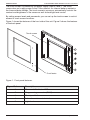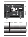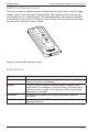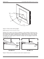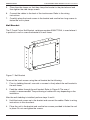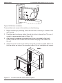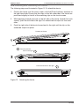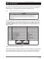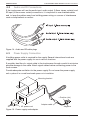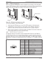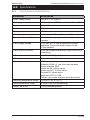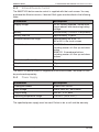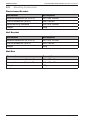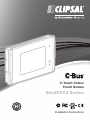
1
C-Touch Colour
Touch Screen
50x0CTC3 Series
Installation Instructions
50x0CTC3 Series
C-Touch Colour Touch Screen Installation Instructions
Contents
1.0 Product Description ........................................................................................3
1.1 Features and Capabilities ..........................................................................3
1.2 Infrared Remote Control ............................................................................6
1.3 Definitions ..................................................................................................6
2.0 Safety and Product Handling .........................................................................7
3.0Installation ......................................................................................................7
3.1 Location .....................................................................................................7
3.2 Multiple Touch Screen Units ......................................................................8
3.3 Mounting Instructions ................................................................................9
3.4 Attaching and Removing the Fascia ........................................................13
4.0 Wiring Details ................................................................................................15
4.1 C-Bus Network Connection .....................................................................15
4.2 Audio and IR Connections .......................................................................16
4.3 Power Supply Connection ........................................................................16
4.4 USB Connections.....................................................................................17
4.5 RS232 Serial Connection ........................................................................17
4.6 Wired LAN Connection ............................................................................18
4.7 Keyboard Connections .............................................................................18
4.8 Programming Lead ..................................................................................18
5.0 C-Bus Programming Requirements ............................................................19
6.0 Using the C-Touch Colour Utility ................................................................20
7.0 Reset Button .................................................................................................26
8.0Specifications ...............................................................................................27
8.1 Touch Screen Specifications ....................................................................27
8.2 Touch Screen Dimensions .......................................................................28
8.3 Infrared Remote Control ..........................................................................29
8.4 Power Supply ...........................................................................................29
8.5 Mounting Accessories .............................................................................30
9.0 Standards Complied .....................................................................................31
10.0 Two-Year Warranty ........................................................................................32
© Copyright 2012. Schneider Electric Australia Pty Ltd. All rights reserved.
The information in this document is provided in good faith. Schneider Electric Australia Pty Ltd
has endeavoured to ensure the relevance and accuracy of the information, but assumes no
responsibility for any loss incurred as a result of its use. Schneider Electric does not warrant
that the information is fit for any particular purpose, nor does it endorse its use in applications
that are critical to the health or life of any human being. Schneider Electric reserves the right to
update the information at any time without notice.
C-Bus, Clipsal, C-Touch and HomeGate are trademarks of Schneider Electric Industries SAS.
All other trademarks are the property of their respective owners.
April 2012
© 2012 Schneider Electric. All Rights Reserved.
50x0CTC3 Series
C-Touch Colour Touch Screen Installation Instructions
1.0 Product Description
The C-Bus C-Touch Colour Touch Screen provides sophisticated control of an entire
system from one location. Using the appropriate software, you can:
• configure the screens (pages) for convenience of use
• control devices, scenes and schedules
• configure an audible alarm
• display video from a camera connected to the local LAN.
Several fascia colour and style options are available. Contact your local sales
representative for more information.
The touch screen, parts and accessories are listed in Table 1.
Catalogue Number
Description
50x0CTC3
Colour 6.4” backlit LCD touch screen, wall-mount,
base unit for use with Saturn or Neo front fascia.
Parts Package: stylus, microfibre cleaning cloth,
mounting screws, RJ45 plugs and a programming
cable (included parts)
5035TX2
C-Bus infrared remote control, 5-button
(included part).
Accessories, Ordered Separately
5100PS24/2700-AU
Power supply, 24V d.c., 2.7A, 65W, 100-240V a.c.,
with AC power cord and adapter cable.
5000CTCWB
Wall box, for masonry, brick or timber/metal framed
stud walls.
5000CTCNA
Nail bracket, for screw or nail attachment to a wall
frame.
5000CTCRM
Plasterboard bracket.
Table 1. Colour touch screen, parts and accessories
1.1 Features and Capabilities
The colour touch screen is a wall-mounted unit available with several fascia styles
and colours. Mounting brackets are available for a variety of mounting conditions.
The colour touch screen includes an infrared (IR) window for remote control
interface and a hand held C-Bus remote control.
To program the touch screen, a PC is connected to the LAN interface, located
behind the fascia. The unit can also be programmed via a normal LAN connection
on the rear panel. Clipsal Toolkit and PICED configuration software tools are
downloaded from the Clipsal website. Projects are created using PICED and are
transferred to the touch screen.
© 2012 Schneider Electric. All Rights Reserved.
3 of 36
50x0CTC3 Series
C-Touch Colour Touch Screen Installation Instructions
The touch screen is powered by the power supply listed in Table 1. The touch
screen does not supply power to the C-Bus network. An internal battery maintains
the time and date settings. The touch screen’s processor automatically controls the
contrast and brightness of the screen as well as backlight level control.
By setting access levels and passwords, you can set up the touch screen to restrict
access to touch screen functions.
Figure 1 shows the features of the front side of the unit. Figure 2 shows the features
of the back panel.
Touch screen
Front fascia
Figure 1. Front panel features.
Figure Reference
4 of 36
Description
1
Power on/off indicator LED
2
Programming connector (RJ45)
3
Reset pushbutton
4
Infrared remote control window
5
Light level sensor
© 2012 Schneider Electric. All Rights Reserved.
50x0CTC3 Series
C-Touch Colour Touch Screen Installation Instructions
DC IN
+ -
Figure 2. Back panel connection points.
Figure Reference
Connections and Features
Description
1
Ethernet LAN
RJ45
2
Memory card
Compact Flash
3
C-Bus network
2 x RJ45
4
Serial interface
DE9
5
IR control input
3.5mm mono jack
6
Audio line input
3.5mm stereo jack
7
Audio line output
3.5mm stereo jack
8
USB
2 x USB A
9
Power supply
2-terminal plug
10
Keyboard
PS/2
© 2012 Schneider Electric. All Rights Reserved.
5 of 36
50x0CTC3 Series
C-Touch Colour Touch Screen Installation Instructions
1.2 Infrared Remote Control
The touch screen is supplied with an infrared remote control that is used to trigger
scenes, switch loads and adjust lighting levels. The remote control functions are
incorporated into a software project. During programming, the functions available
to the remote control are set. If multiple touch screen units are installed, the same
remote control can talk to each of them.
Figure 3. Infrared (IR) remote control.
1.3 Definitions
Term
Definition
Load
An electrical device (such as a light) connected to a C-Bus
output unit (such as a dimmer).
Scene
A series of actions across multiple outputs, triggered by a
single button. For example, on arrival home, you could use a
scene to switch on lights in the hallway, kitchen and lounge,
and switch on a heater.
Schedule
A sequence of events set to occur at particular times in
the future.
Backlight
The light behind the LCD screen providing visibility in varying
lighting conditions.
6 of 36
© 2012 Schneider Electric. All Rights Reserved.
50x0CTC3 Series
C-Touch Colour Touch Screen Installation Instructions
2.0 Safety and Product Handling
Be aware of the following information during installation:
• The touch screen and its power supply are for indoor use only.
• Use only the approved power supply with the touch screen (see Table 1).
• Do not connect the C-Bus cables to any other network. Damage to the
equipment will occur.
• Allow adequate ventilation. Do not block the air vents at the top of the unit.
• Using any non-C-Bus software on the touch screen without the written consent
of Clipsal or Schneider Electric may void the unit’s warranty.
• Do not overtighten the mounting screws. The case might distort and cause
problems installing the front fascia.
• Do not megger test the touch screen or the C-Bus network cables.
• Use only the cleaning cloth provided to clean the screen.
3.0 Installation
When installing the touch screen, be careful not to scratch or otherwise damage the
plastic parts. Do not wipe the screen with anything other than the a clean soft cloth.
Refer to the User’s Guide for care instructions.
3.1 Location
It is important to select the right location for the touch screen. Follow these
guidelines when choosing a location for the unit:
• Choose a location away from direct sunlight or bright lights that will cause
unwanted reflections.
• Avoid damp or humid locations or places where water might drip on the
touch screen.
• Provide a clear area in front of the touch screen for reception of signals from the
infrared remote control.
• The touch screen viewing angle is shown in Figure 4.
• Do not install the touch screen near sources of heat, such as hot air vents
or heaters.
© 2012 Schneider Electric. All Rights Reserved.
7 of 36
50x0CTC3 Series
C-Touch Colour Touch Screen Installation Instructions
60˚ up
70˚ left
60˚ down
70˚right
Figure 4. Touch screen viewing angles.
3.2 Multiple Touch Screen Units
Multiple touch screen units may be installed on a C-Bus network. These units may
be programmed to operate cooperatively or independently of each other. Take care
not to mount units where a single IR remote control transmission can be received
by multiple units (see Figure 5). Otherwise, multiple units may trigger a scene with
unpredictable results.
Figure 5. Take care not to overlap remote control reception zones.
8 of 36
© 2012 Schneider Electric. All Rights Reserved.
50x0CTC3 Series
3.3
C-Touch Colour Touch Screen Installation Instructions
Mounting Instructions
There are three options for mounting the touch screen:
• in plasterboard walls using a plasterboard bracket
• in stud walls (such as timber frame internal walls) using a nail bracket
• in solid walls (such as brick or stone) or stud walls using a wall box
Plasterboard Bracket
The C-Touch Colour Plasterboard Bracket (catalogue number 5000CTRM) provides
a means of mounting the touch screen in a plasterboard wall.
In order to install the bracket, there must be an empty space behind the
plasterboard that is 310mm wide and 65mm deep. This space is required to insert
and rotate the bracket. The opening for the bracket is 208mm wide and 162mm high.
Figure 6. Plasterboard bracket installation
To install the plasterboard bracket:
1. Cut out a 208mm x 162mm hole in the plasterboard.
2. Drill four 4mm holes in the plasterboard to provide clearance for the screws that
secure the touch screen.
3. Using the four short screws provided, attach the side clamps to the bracket
body. Do not tighten the screws at this time.
4. Insert the bracket in the cut out hole (see Figure 6) and then rotate the bracket
inside the wall cavity until it matches the cut out.
© 2012 Schneider Electric. All Rights Reserved.
9 of 36
50x0CTC3 Series
C-Touch Colour Touch Screen Installation Instructions
5. Place the side clamps so that they clamp the bracket to the plasterboard and
then tighten the side clamp screws.
6. Connect the cables to the back of the touchscreen. Refer to the wiring
instructions.
7. Carefully place the touch screen in the bracket and use the four long screws to
fasten the unit in place.
Nail Bracket
The C-Touch Colour Nail Bracket, catalogue number 5000CTCNA, is used where it
is practical to nail or screw the bracket to a wall frame.
Figure 7. Nail Bracket
To mount the touch screen using the nail bracket do the following:
1. Prior to cladding the wall, use nails or screws to firmly attach the nail bracket to
the wall frame.
2. Feed the cables through the nail bracket. Refer to Figure 8. The use of
conduit is recommended. The positioning of cables will vary depending on the
installation.
After the wall cladding is installed, perform steps 3 and 4.
3. Hold the touch screen up to the bracket and connect the cables. Refer to wiring
instructions in this document.
4. Place the unit in the bracket and use the four screws provided to fasten the unit
in place. Do not overtighten the screws.
10 of 36
© 2012 Schneider Electric. All Rights Reserved.
50x0CTC3 Series
C-Touch Colour Touch Screen Installation Instructions
Figure 8. Nail bracket installation detail
Wall Box
The C-Touch Colour Wall Box, catalogue number 5000CTCWB, allows the touch
screen to be mounted in a solid wall construction such as brick or stone. It provides
better RF shielding than the nail bracket. The wall box may also be used to mount
the touch screen in timber or metal-frame stud walls.
Note: If you use an optional Wi-fi adapter (not provided), the device must be
placed outside of the wall box for proper reception. During installation, use
a USB extension cable and pass the adapter through one of the holes in
the wall box.
Figure 9. Wall box
© 2012 Schneider Electric. All Rights Reserved.
11 of 36
50x0CTC3 Series
C-Touch Colour Touch Screen Installation Instructions
Figure 10. Wall box installation
To mount the touch screen in the wall box, do the following:
1. Before rendering or plastering, attach the wall box to masonry or a beam of the
wall framing.
2. Feed the signal and power cables through the holes in the wall box. The use of
conduit is recommended (refer to Figure 10).
3. After the wall is rendered or plastered and a hole is provided for the touch
screen, hold the touch screen near the wall box and plug in the cables into
the unit.
4. Attach the touch screen to the wall box using the 4 screws provided. Make sure
that the cables are clear of the mounting screws. Do not overtighten the screws.
Figure 11. 4 screws hold the touch screen in place.
12 of 36
© 2012 Schneider Electric. All Rights Reserved.
50x0CTC3 Series
C-Touch Colour Touch Screen Installation Instructions
3.4 Attaching and Removing the Fascia
The following steps are illustrated in Figure 12. To attach the fascia:
1. Position the fascia over the touch screen, with the IR and indicator windows on
the right hand side. Ensure that the clips on the left underside of the fascia are
positioned slightly to the left of the matching clips on the touch screen.
2. While applying forward pressure on the left side of the fascia (toward the touch
screen), push the left side to the right. You should feel the clips slot into each
other.
3. Push the right side of the fascia forward and to the right until the clip on the
underside snaps into place.
Position the fascia
Clips
Forward pressure
Push to the right
Push forward and to the right
Figure 12. Attaching the fascia.
© 2012 Schneider Electric. All Rights Reserved.
13 of 36
50x0CTC3 Series
C-Touch Colour Touch Screen Installation Instructions
To remove the fascia:
1. Grasp the right side of the fascia with your left hand.
2. Push the release lock in with your right thumb. At the same time lift the right
side of the fascia plate off and to the right with your left hand (to disengage the
clip).
3. Swing the fascia off towards the left. Refer to Figure 13.
Push the
release lock
Lift off and to the right to disengage
the clip, then swing to the left
Figure 13. Removing the fascia.
14 of 36
© 2012 Schneider Electric. All Rights Reserved.
50x0CTC3 Series
C-Touch Colour Touch Screen Installation Instructions
4.0 Wiring Details
All of the wired cable connections to the touch screen use quick disconnecting type
plugs. Be sure to connect the cables to the correct locations before installing the
touch screen in its mounting bracket with the four mounting screws.
4.1
C-Bus Network Connection
Caution
The C-Bus network must not be connected to any other type of network.
Make certain that only the C-Bus network cable is inserted in the
C-Bus RJ45 connectors. Improper connection will cause damage to the
equipment.
Two RJ45 connectors are located on the back panel for C-Bus network connection.
This allows the touch screen to be placed anywhere on the network. Use Cat.5e
Unshielded Twisted Pair (UTP) cable. Catalogue numbers are 5005C305B (solid)
and 5005C305BST(stranded). The pin assignments for the cable conductors are
shown in Table 2
Pin
C-Bus Connection
Colour
1
Remote ON
green & white
2
Remote ON
green
3
C-Bus Negative (-)
orange &white
4
C-Bus Positive (+)
blue
5
C-Bus Negative (-)
blue & white
6
C-Bus Positive (+)
orange
7
Remote OFF
brown & white
8
Remote OFF
brown
87654321
87654321
Table 2. RJ45 cable conductors for C-Bus.
C-Bus network cables must be kept separate from mains cabling. To avoid problems
caused by induced electromagnetic noise, never run the network cable parallel to
mains wiring or place the cable inside a conduit that contains mains conductors.
© 2012 Schneider Electric. All Rights Reserved.
15 of 36
50x0CTC3 Series
4.2
C-Touch Colour Touch Screen Installation Instructions
Audio and IR Connections
If the touchscreen will use the audio input, audio output (3.5mm stereo sockets) and
IR input (3.5mm mono socket) connections, it is important to use shielded cables
and to keep the cables away from building power wiring or sources of interference
such as lamp ballasts or motors.
Figure 14. Audio and IR cable plugs
4.3
Power Supply Connection
A building power outlet is required for the supply. Several international cords are
supplied with the power supply for use in various locations.
If possible, feed the d.c. output cable to the touchscreen through conduit to minimise
possible damage to the cable. Attach signal cables before connecting power to the
touch screen.
Provide adequate ventilation for the power supply. Do not cover the power supply
unit or place it in a small enclosed space or in insulation.
Mounting bracket
+ Positive (dot)
AC power cord
Adapter cable
- Negative
Figure 15. Power supply and adapter.
16 of 36
© 2012 Schneider Electric. All Rights Reserved.
50x0CTC3 Series
4.4
C-Touch Colour Touch Screen Installation Instructions
USB Connections
One or two optional USB devices can be installed in the sockets on the rear panel.
Using a USB extension cable is recommended for all devices. When using extension
cables, place any USB devices outside of the metal box (see Figure 16).
USB extension
Adapter
Figure 16. USB device and extension cable.
To install the adapter, follow these steps:
1. Install optional USB devices in one of the USB sockets on the back panel.
2. In applications using a wall box or nail bracket, a Wi-fi adapter requires an
extension cable and must be placed outside the box for proper reception.
3. When using an extension, attach the cable to the back of the touch screen and
allow excess cable to lie loose in the wall cavity.
4.5
RS232 Serial Connection
The RS-232 serial port connection uses standard EIA 574 pinouts (see Table 3).
The RS-232 port lets you to connect external devices such as security and control
equipment. Be sure to use a suitable shielded data cable. The cable length should
be limited to 15 metres for communication up to 19,200 bps, or 7.5 metres at 38,400
bps.
Pin
12 3 4 5
6789
Name
Description
1
DCD
Data Carrier Detect
2
RD
Receive Data
3
TD
Transmit Data
4
DTR
Data Terminal Ready
5
GND
Ground
6
DSR
Data Set Ready
7
RTS
Request to Send
8
CTS
Clear to Send
9
RI
Ring Indicator
Table 3. RS232 Serial Interface
© 2012 Schneider Electric. All Rights Reserved.
17 of 36
50x0CTC3 Series
4.6
C-Touch Colour Touch Screen Installation Instructions
Wired LAN Connection
Caution
The Ethernet LAN network cable must not be connected to the C-Bus
cable connector on the back panel. The two networks are not electrically
compatible and improper connection will cause damage to the equipment.
The 5000CTC3 touch screen supports a wired Ethernet LAN connection at the rear
panel. The connection method used is a matter of choice. A wired LAN connection
requires a switch/hub or router, not supplied by Clipsal. Be sure to use high quality
Cat.5e cable for the LAN connection. Conduit is recommended. Do not run network
cables near mains power cables or near sources of interference such as light
fixtures or transformers.
4.7
Keyboard Connection
You can connect a keyboard to the touchscreen for configuration and support
purposes. The connection is not intended to be permanent. You can use either of
thefollowing methods to connect a keyboard:
PS/2 Port
The keyboard may be connected directly to the PS/2 port.
USB Ports
You can connect a USB keyboard to either of the USB ports on the back panel.
Use care when the touch screen is not firmly attached to the mounting box or
bracket. After completing the programming tasks, be sure to securely attach the
touchscreen and install the front fascia.
4.8
Programming Lead
A programming lead is provided with the touch screen. It consists of a Cat.5e
crossover Ethernet patch cable. Use the crossover programming lead when
connecting directly from a PC to the touch screen. If connecting through a network
hub or switch, you will need to use a standard Ethernet cable. Cable conductor
assignments for a crossover Ethernet cable are shown in Table 4.
12345678
Connection A
Connection B
1
3
Colour
Green/White
2
6
Green
3
1
Orange/White
4
4
Blue
5
5
Blue/White
6
2
Orange
7
7
Brown/White
8
8
Brown
Table 4. Wiring assignments for a crossover Ethernet patch cable.
18 of 36
© 2012 Schneider Electric. All Rights Reserved.
50x0CTC3 Series
C-Touch Colour Touch Screen Installation Instructions
5.0 C-Bus Programming Requirements
Unit Address
The touch screen must be programmed with a unique identification address (unit
address). This is accomplished using C-Bus Toolkit software, available from the
Downloads section of the Clipsal Integrated Systems (CIS) web site at:
http://www.clipsal.com/cis.
System Clock and Burden
C-Bus Toolkit is also used to enable the system clock and burden, if required.
The unit incorporates a software selectable C-Bus system clock that is used for
synchronizing data commmunications on the network. A maximum of three enabled
system clocks should exist on a network, so the system clock on the touch screen is
disabled by default.
Colour Touch Screen Project
The touch screen must be configured for a particular C-Bus installation with
a project that has been produced using the Programming Interface for C-Bus
Embedded Devices (PICED) software. PICED software is available from the
Downloads section of the CIS web site. Documentation and Help files are included
with the software.
After you have produced a project, select the ‘Transfer Project To C-Touch Colour’
option located in the Transfer drop down menu. The C-Touch Colour Transfer Utility
software sends the project to the unit via the Ethernet LAN. The utility is included
with PICED software and allows you to perform various configuration functions,
such as setting the time.
The installer should make copies of the Toolkit and PICED project files and also
give a copy to the customer.
© 2012 Schneider Electric. All Rights Reserved.
19 of 36
50x0CTC3 Series
C-Touch Colour Touch Screen Installation Instructions
6.0 Using the C-Touch Colour Utility
The C-Touch Colour Transfer Utility transfers a software project to the touch screen.
The utility is included with PICED software that is available from the Downloads
section of the CIS web site: http://www.clipsal.com/cis.
This section takes you through the process of installing a project on the C-Touch
touch screen using a direct Ethernet connection. It is also possible to install projects
to multiple C-Touch touch screen units via a common DHCP network, or a network
where each touch screen has been configured with a unique static IP Address.
1. After the touch screen has been installed and switched on, the default screen
appears (see Figure 17). You must configure the unit with an IP address and a
customised project file before the touch screen is ready for use.
Figure 17. The initial screen of an unconfigured colour touch screen
20 of 36
© 2012 Schneider Electric. All Rights Reserved.
50x0CTC3 Series
C-Touch Colour Touch Screen Installation Instructions
2. If your PC and the touch screen are both connected to a common Ethernet
network, start the C-Touch Transfer Utility by clicking the C-Touch Transfer
Utility in the PICED folder in the windows start menu, or select ‘Transfer to Unit’
in PICED‘s Transfer menu and continue to Step 11. If both devices are not
connected to a common network, continue with Step 3.
3. Remove the fascia if it has been fitted to the unit.
4. Plug the supplied programming lead (red crossover cable) into the RJ45 socket
on the front right side of the touch screen.
5. Ensure that your PC is switched on and plug the other end of the crossover
cable into the Ethernet socket on your PC.
6. Start the C-Touch Transfer Utility by clicking the C-Touch Transfer Utility in the
PICED folder in the windows start menu, or select ‘Transfer to Unit’ in PICED‘s
Transfer menu.
7. If your PC has multiple network adapters (that are enabled), you see a list of
available network devices. If the screen is not displayed, click Select Network
Adapter from the Search menu. Select the network adapter where the patch
cable is connnected and Click OK (see Figure 18).
Figure 18. Select the network adapter used to connect to the C-Touch Colour
© 2012 Schneider Electric. All Rights Reserved.
21 of 36
50x0CTC3 Series
C-Touch Colour Touch Screen Installation Instructions
8. You will be asked to select the type of network. Select Direct Connect and then
click OK (see Figure 19).
Figure 19. Select the network connection type
9. The transfer utility software will suggest an IP Address for the touch screen (see
Figure 20). Click Next to attempt to set the IP Address for the touch screen that
is connected to your PC. You will be asked to confirm the suggested IP Address
on the touch screen.
Figure 20. An IP Address will be suggested for the touch screen
22 of 36
© 2012 Schneider Electric. All Rights Reserved.
50x0CTC3 Series
C-Touch Colour Touch Screen Installation Instructions
10. You will now see the touch screen unit listed in the transfer utility (see Figure
21).
Figure 21. List of touch screens located by the search
11. Select the touch screen to be configured. The screen provides information
about the selected touch screen (see Figure 22).
Figure 22. Touch screen information screen
12. If there is a firmware update for your touch screen, you will be prompted to
update before you are allowed to change the project or other settings.
© 2012 Schneider Electric. All Rights Reserved.
23 of 36
50x0CTC3 Series
C-Touch Colour Touch Screen Installation Instructions
13. Click the Transfer tab to select the transfer page. The transfer options allow you
to transfer a project to the touch screen or transfer a project or log file to your
PC.
14. Select the button for the Transfer Project to C-Touch Colour. Choose the project
that was created for this touch screen installation. Then press Start to begin the
transfer process.
It may take several minutes for the transfer to complete. An information screen
tells you that the transfer was sucessful (see Figures 23 and 24).
Figure 23. Choosing the type of transfer to be done
Figure 24. The project has been successfully transferred to the touch screen
24 of 36
© 2012 Schneider Electric. All Rights Reserved.
50x0CTC3 Series
C-Touch Colour Touch Screen Installation Instructions
15. Click the Control tab to select the Control page. From the control screen, you
can take a screen grab of the touch screen and change the name that identifies
the touch screen over the Ethernet connection (see Figure 25).
Figure 25. Changing the name of the C-Touch Colour unit
Figure 26. Confirming the name change
Note: Using the touch screen on a network is similar to direct connection. You
might need the assistance from a network administrator.
© 2012 Schneider Electric. All Rights Reserved.
25 of 36
50x0CTC3 Series
C-Touch Colour Touch Screen Installation Instructions
7.0 Reset Button
In the event that the C-Touch Colour software becomes unresponsive, you can reset
the touch screen by pressing the reset button.
The reset button is located to the right of the display, beneath the fascia (see
Figure 27). Instructions for removing the fascia are provided earlier in this document.
Fascia release latch
Reset button
IR sensor
Light sensor
Figure 27. The reset button is located underneath the fascia
26 of 36
© 2012 Schneider Electric. All Rights Reserved.
50x0CTC3 Series
C-Touch Colour Touch Screen Installation Instructions
8.0Specifications
8.1
Touch Screen Specifications
Parameter
Description
Power supply rating
24V d.c., 2.7A, class 2
Display type
16.3cm (6.4 in.) TFT Colour Active Matrix LCD
Display resolution
640 x 480 pixels
Display luminance
600 cd/m² minimum
Display contrast ratio
>400:1
Viewing angle
Left and right: 70°, up: 60°, down: 60°
Touch surface durability
35 touches in any one location, 1 million slide
touches
C-Bus supply voltage
15 to 36V d.c. @ 20mA required for normal
operation. Does not provide current for the
C-Bus network.
C-Bus control functions
Load switching and dimming, scene control and
scheduling
C-Bus connection
2 x C-Bus RJ45 (parallel)
C-Bus system clock
Software selectable
Other connections
USB type A x 2
Ethernet, RJ45 x 2, one front and one back
Serial interface, DE9
Audio line IN, 3.5mm stereo
Audio line OUT, 3.5mm stereo
Infrared IN, 3.5mm mono
Keyboard, PS/2 or USB
Power, 2-pin screw terminal, quick disconnect
Operating temperature range
-5 to 45°C (23 to 113°F)
Operating humidity range
5 to 90% RH (non-condensing)
Weight, base unit
1254g (excluding fascia)
© 2012 Schneider Electric. All Rights Reserved.
27 of 36
50x0CTC3 Series
8.2
C-Touch Colour Touch Screen Installation Instructions
Touch Screen Dimensions
Parameter
Description
Dimensions (W x H x D)
246 x 173 x 72.5mm (excluding fascia)
Protrusion from wall
23.5mm (including fascia)
Mounting depth (into wall)
54mm
Mounting centres (H x V)
212.5 x 112mm
24 6 mm
202 mm
18.5 mm
54 mm
158
mm
173
mm
234 mm
Note:
28 of 36
The touch screen in this example has a bevelled glass fascia.
© 2012 Schneider Electric. All Rights Reserved.
50x0CTC3 Series
8.3
C-Touch Colour Touch Screen Installation Instructions
Infrared Remote Control
The 5035TX2 5-button remote control is supplied with the touch screen. You may
purchase the 8-button version, if desired. Both types are described in the following
table.
Parameter
Description
Supply voltage
3V d.c. battery powered. Transmission
range reduces with decreasing battery
voltage.
Battery
Lithium battery (CR2025, or equivalent)
Battery shelf life
Approximately 10 years
Infrared transmission range
Approximately 8m at 90°, or
4m at 60° to the touch screen
Control functions
5035TX2: 5 membrane buttons
including master off. Also up and down
button
5038TX2: 8 membrane buttons
including master off. Also up and down
buttons
Dimensions (W x H x D)
86 × 54 × 8mm
Weight
28g
Colour
White
The 5035TX2 remote control is supplied with the touch screen. The 5038TX2 can
be purchased separately.
8.4
Power Supply
Parameter
Description
Catalogue number
5100PS24/2700-AU
Input voltage
100 to 240V a.c., 50 or 60Hz
Output rating
24V d.c., 2.7A, 65W
Operating temperature range
-5 to 50°C (23 to 122°F)
The specified power supply must be used. Failure to do so will void the warranty.
© 2012 Schneider Electric. All Rights Reserved.
29 of 36
50x0CTC3 Series
8.5
C-Touch Colour Touch Screen Installation Instructions
Mounting Accessories
Plasterboard Bracket
Parameter
Description
External dimensions (W x H x D)
261 x 200 x 44mm
Cut-out dimensions (W x H)
208 x 162mm
Required cavity clearance
310 x 310 x 65mm
Weight
296g
Nail Bracket
Parameter
Description
External dimensions (W x H x D)
287 x 215 x 47mm
Cut-out dimensions (W x H)
205 x 162mm
Weight
530g
Wall Box
Parameter
Description
External dimensions (W x H x D)
224 x 167 x 68mm
Cut-out dimensions (W x H x D)
219 x 162 x 67mm
Weight
667g
30 of 36
© 2012 Schneider Electric. All Rights Reserved.
50x0CTC3 Series
C-Touch Colour Touch Screen Installation Instructions
9.0 Standards Complied
Declarations of Conformity
Australian/New Zealand EMC & Electrical Safety Frameworks and Standards
Regulation
Standard
Title
Safety
AS/NZS 60950-1
Information Technology Equipment-Product Safety
EMC
AS/NZS CISPR22
Information Technology Equipment--
(Class B)
Radio Disturbance Characteristics
European Directives and Standards
Directive
Standard
Title
EMC Directive
CISPR 22, EN
Information Technology Equipment--
2004/108/EC
55022 (Class B)
Radio Disturbance Characteristics
CISPR 24,
Information Technology Equipment--
EN 55024
Immunity Characteristics
EN 60950-1
Information Technology Equipment
Low Voltage Directive
2006/95/EC
RoHS Directive
Reduction of Hazardous Substances
2011/65/EU
Other International Standards
Standard
Title
IEC 60950-1
Information Technology Equipment -- Safety
CISPR 22
Information Technology Equipment -- Radio disturbance
characteristics -- Limits and methods of measurement
CISPR 24
Information Technology Equipment -- Immunity
characteristics -- Limits and methods of measurement
US FCC Regulations
Regulation
Title
FCC Title 47
Part 15, Subpart B, Class B Digital Device
This device complies with part 15 of the FCC rules. Operation is subject to the following two
conditions: (1) this device may not cause harmful interference, and (2) this device must accept
any interference received, including interference that may cause undesirable operation.
(continued on next page)
© 2012 Schneider Electric. All Rights Reserved.
31 of 36
50x0CTC3 Series
C-Touch Colour Touch Screen Installation Instructions
US FCC Regulations (continued)
Class B Product
Note:
This equipment has been tested and found to comply with the limits for a Class B digital device, pursuant
to Part 15 of the FCC Rules. These limits are designed to provide reasonable protection against harmful
interference in a residential installation. This equipment generates, uses and can radiate radio frequency
energy and, if not installed and used in accordance with the instructions, may cause harmful interference
to radio communications. However, there is no guarantee that interference will not occur in a particular
installation.
If this equipment does cause harmful interference to radio or television reception, which can be determined
by turning the equipment off and on, the user is encouraged to try to correct the interference by one or more
of the following measures:
• Reorient or relocate the receiving antenna.
• Increase the separation between the equipment and receiver.
• Connect the equipment into an outlet on a circuit different from that to which the receiver is connected.
• Consult the dealer or an experienced radio/TV technician for help.
Changes or modifications to this device that are not expressly approved by Schneider Electric (Australia) Pty
Ltd could void the user’s authority to operate the equipment.
Underwriters Laboratories
32 of 36
UL60950-1
Information Technology Equipment
CSA 22.2
Information Technology Equipment -- Safety
© 2012 Schneider Electric. All Rights Reserved.
50x0CTC3 Series
C-Touch Colour Touch Screen Installation Instructions
10.0 Two-Year Warranty
The 5000CTC3 Series C-Touch Colour Touch Screen carries a two-year warranty
against manufacturing defects.
Warranty Statement
The benefits conferred herein are in addition to, and in no way shall be deemed to
derogate, either expressly or by implication, any or all other rights and remedies in
respect to the Clipsal by Schneider Electric product, that the consumer has in the
location where the product is sold.
The warrantor is Schneider Electric (Australia) Pty Ltd, a member of Schneider
Electric Industries SAS, with offices worldwide.
This Clipsal by Schneider Electric product is guaranteed against faulty workmanship
and materials for a period of two (2) years from the date of purchase.
Schneider Electric (Australia) Pty Ltd reserves the right, at its discretion, to either
repair free of parts and labour charges, replace or offer refund in respect to any
article found to be faulty due to materials, parts or workmanship.
This warranty is expressly subject to the Clipsal by Schneider Electric product being
installed, wired, tested, operated and used in accordance with the manufacturer’s
instructions. Any alterations or modifications made to the product without permission
of Schneider Electric (Australia) Pty LTD might void the warranty.
Schneider Electric (Australia) Pty Ltd shall meet all costs of a claim. However,
should the product that is the subject of the claim be found to be in good working
order, all such costs shall be met by the claimant.
When making a claim, the consumer shall forward the Clipsal by Schneider Electric
product to the nearest Clipsal by Schneider Electric office. Provide adequate
particulars of the defect within 28 days of the fault occurring. The product should be
returned securely packed, complete with details of the date and place of purchase,
description of the load and circumstances of the malfunction.
For all warranty enquiries, contact your local Clipsal by Schneider Electric Sales
Office. The address and contact number can be found at the web site:
www.clipsal.com/locations or by telephoning 1300 722 247, the CIS Technical
Support Hotline (Australia only).
© 2012 Schneider Electric. All Rights Reserved.
33 of 36
50x0CTC3 Series
C-Touch Colour Touch Screen Installation Instructions
Notes:
34 of 36
© 2012 Schneider Electric. All Rights Reserved.
50x0CTC3 Series
C-Touch Colour Touch Screen Installation Instructions
Notes:
© 2012 Schneider Electric. All Rights Reserved.
35 of 36
Technical Support
For further assistance in using this product, consult your nearest Clipsal Integrated
Systems (CIS) Sales Representative or Technical Support Officer.
Technical Support Contact Numbers
Australia
1300 722 247 (CIS Technical Support Hotline)
New Zealand
0800 888 219 (CIS Technical Support Hotline)
United States
1 888 778 2733
[email protected]
Technical Support email: [email protected]
Schneider Electric (Australia) Pty Ltd
Contact us: clipsal.com/feedback
National Customer Care Enquiries:
Tel 1300 2025 25
Fax 1300 2025 56
F2337/01
Schneider Electric (Australia) Pty Ltd reserves the right to
change specifications, modify designs and discontinue items
without incurring obligation and whilst every effort is made to
ensure that descriptions, specifications and other information
in this catalogue are correct, no warranty is given in respect
thereof and the company shall not be liable for any error therein.
© 2012 Schneider Electric. All Rights Reserved.
Trademarks are owned by Schneider Electric Industries SAS or
its affiliated companies.
CLIPCOM Mar 2012