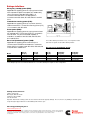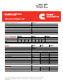
1
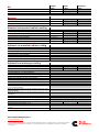
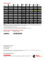
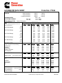
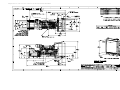
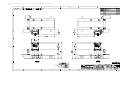
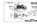
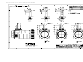
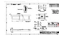
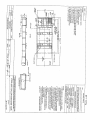
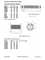
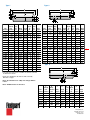
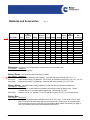
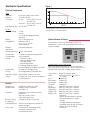
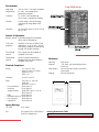
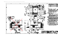
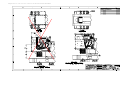
Bill of Materials Re: 2250KW Item Install-US-Stat 2250DQKH A331-2 L090-2 L097-2 R002-2 B453-2 H611-2 H605-2 H606-2 H608-2 KP80-2 H666-2 C127-2 A334-2 A333-2 E041-2 H556-2 D041-2 H607-2 L028-2 0416-0527 BA BC VI CM EF EN FT Description Diesel Genset: 60Hz-2250kW Installation-In USA, Stationary Genset-Diesel, 60Hz, 2250kW-Standby Rating Duty Rating-Standby Power Listing-UL 2200 Emissions-EPA, Tier1, NR Levels CI Voltage-277/480,3 Phase,Wye,4 Wire Alt-60Hz,Y480V,150-105C-SPC,40C amb Set Control-PCC Display-Control, Graphical Meters-AC Output, Analog Control Mounting-Right Facing Circuit Breaker – 3000A Breaker Indication-Ground Fault, 3-Pole Xfr Sw, Rmt Mt CT Separator-Fuel/Water Engine Starter-24 VDC Motor Battery Charging Alternator-Normal Output Engine Cooling-Radiator Coolant Heater-208/240/480V Engine Air Cleaner-Normal Duty Filters-Engine Oil, Full Flow and Bypass Genset Warranty-1 Year Comprehensive Battery Rack & Hold down Assembly Batteries Battery Charger Vibration Isolators Critical Muffler (Shipped Loose) Exhaust Flex (Shipped Loose) Weather Protective Enclosure 24 Hour Subbase Fuel Tank Qty 1 1 1 1 1 1 1 1 1 1 1 1 1 1 1 1 1 1 1 1 1 1 1 1 1 1 1 1 1 Diesel generator set QSK60 series engine EPA emissions 1450 kW - 2250 kW 60 Hz 1200 kW - 2000 kW 50 Hz Description Features Cummins Power Generation commercial generator sets are fully integrated power generation systems providing optimum performance, reliability and versatility for stationary, prime power and continuous duty power applications. Cummins heavy-duty engine - Rugged 4-cycle, industrial diesel delivers reliable power, low emissions and fast response to load changes. This generator set is designed in facilities certified to ISO9001 and manufactured in facilities certified to ISO9001 or ISO9002. The Prototype Test Support (PTS) program verifies the performance integrity of the generator set design. Cummins Power Generation products bearing the PTS symbol meet the prototype test requirements of NFPA 110 for Level 1 systems. All low voltage models are CSA certified to product class 4215-01. The generator set is available Listed to UL 2200, Stationary Engine Generator Assemblies. The PowerCommand control is Listed to UL 508 - Category NITW7 for U.S. and Canadian usage. Circuit breaker assemblies are UL 489 Listed for 100% continuous operation and also UL 869A Listed Service Equipment. U.S. EPA All 60 Hz models comply with EPA emissions requirements for stationary applications. Some 60 Hz models comply with EPA TPEM requirements for mobile applications. ® Alternator - Several alternator sizes offer selectable motor starting capability with low reactance 2/3 pitch windings, low waveform distortion with non-linear loads and fault clearing short-circuit capability. Permanent magnet generator - Offers enhanced motor starting and fault clearing short-circuit capability. ® Control system - The PowerCommand electronic control is standard equipment and provides total genset system integration including automatic remote starting/stopping, precise frequency and voltage regulation, alarm and status message display, AmpSentry™ protection, output metering, autoshutdown at fault detection and NFPA 110 Level 1 compliance. Cooling system - Standard integral set-mounted radiator system, designed and tested for rated ambient temperatures, simplifies facility design requirements for rejected heat. NFPA - The genset accepts full rated load in a single step in accordance with NFPA 110 for Level 1 systems. Warranty and service - Backed by a comprehensive warranty and worldwide distributor network. Prime rating 60 Hz 50 Hz kW (kVA) kW (kVA) Continuous rating 60 Hz 50 Hz kW (kVA) kW (kVA) Data sheets Model Standby rating 60 Hz 50 Hz kW (kVA) kW (kVA) 60 Hz 50 Hz DQKB 1750 (2188) 1500 (1875) 1600 (2000) 1350 (1688) 1450 (1813) 1200 (1500) D-3220/3224 D-3221 DQKC 2000 (2500) 1650 (2063) 1825 (2281) 1500 (1875) 1600 (2000) 1200 (1500) D-3222/3225 DQKD DQKH 1800 (2250) 2250 (2813) 1600 (2000) 1320 (1650) 2000 (2500) ©2007|Cummins Power Generation Inc.|All rights reserved|Specifications subject to change without notice|Cummins Power Generation and Cummins are registered trademarks of Cummins Inc. PowerCommand, AmpSentry and “Our energy working for you.” are trademarks of Cummins Power Generation. Other company, product or service names may be trademarks or service marks of others. S-1383p (9/07) D-3223 D-3250 D-3235 D-3236 Generator set specifications Governor regulation class Voltage regulation, no load to full load Random voltage variation Frequency regulation Random frequency variation Radio frequency emissions compliance ISO8528 Part 1 Class G3 ± 0.5% ± 0.5% Isochronous ± 0.25% IEC 801.2 through IEC 801.5; MIL STD 461C, Part 9 Engine specifications Design Bore Stroke Displacement Cylinder block 4 cycle, V-block, turbocharged and low temperature aftercooled 158.8 mm (6.25 in) 190.0 mm (7.48 in) 3 60.2 litres (3673 in ) Cast iron, 60°V, 16 cylinder 2200 amps minimum at ambient temperature of -18 °C to 0 °C (0 °F to 32 °F) 40 amps 24 volt, negative ground Direct injection: number 2 diesel fuel Triple element, 10 micron filtration, spin-on fuel filters with water separator Dry replaceable element Four spin-on, combination full flow and bypass filters 104 °F (40 °C) ambient radiator Battery capacity Battery charging alternator Starting voltage Fuel system Fuel filter Air cleaner type Lube oil filter type(s) Standard cooling system Alternator specifications Design Stator Rotor Brushless, 4 pole, revolving field 2/3 pitch Single bearing, flexible disc Class H is available on low and medium voltage, Class F is available on high voltage 150 ºC standby PMG (permanent magnet generator) A (U), B (V), C (W) Direct drive centrifugal blower fan < 5% no load to full linear load, < 3% for any single harmonic < 50 per NEMA MG1-22.43 <3 Insulation system Standard temperature rise Exciter type Phase rotation Alternator cooling AC waveform total harmonic distortion Telephone influence factor (TIF) Telephone harmonic factor (THF) Available voltages 60 Hz line-neutral/line-line • 219/380 • 277/480 • 2400/4160 • 254/440 • 347/600 • 7200/12470 • 7620/13200 • 7970/13800 50 Hz line-neutral/line-line • 220/380 • 240/415 • 1905/3300 • 230/400 • 254/440 • 3640/6300 • 3810/6600 • 6350/11000 * Note: Consult factory for other voltages. Generator set options and accessories Engine Low exhaust emission configuration DQKB 60 Hz, 5.5 g/hp-hr NOx data sheet D-3224 DQKC 60 Hz, 5.5 g/hp-hr NOx data sheet D-3225 208/240/480 V coolant heater for ambient above 4.5 °C (40 °F) 208/240/480 V coolant heater for ambient below 4.5 °C (40 °F) High capacity oil pan Control panel 120/240 V, 100 W control anticondensation space heater Paralleling configurations Remote fault signal package Run relay package Exhaust system Industrial grade exhaust silencer Residential grade exhaust silencer Critical grade exhaust silencer Alternator 80 °C rise alternator 105 °C rise alternator 125 °C rise alternator 120/240 V, 300 W anticondensation heater Temperature sensor - RTDs, 2/phase Temperature sensor - alternator bearing RTD Differential current transformers Cooling system Radiator, 50 °C ambient Heat exchanger cooling Remote radiator cooling * Note: Some options may not be available on all models - consult factory for availability. Our energy working for you.™ www.cumminspower.com ©2007|Cummins Power Generation Inc.|All rights reserved|Specifications subject to change without notice|Cummins Power Generation and Cummins are registered trademarks of Cummins Inc. PowerCommand, AmpSentry and “Our energy working for you.” are trademarks of Cummins Power Generation. Other company, product or service names may be trademarks or service marks of others. S-1383p (9/07) Generator set DQKC 60 Hz, 5.5 g/hp-hr NOx data sheet D-3225 208/240/480 V coolant heater Batteries Battery Rack w/hold-down - floor standing Circuit breaker - set mounted Disconnect switch - set mounted PowerCommand network Remote annunciator panel Spring isolators 2 year warranty 5 year warranty 10 year major components warranty Control system Operator panel features Standard control functions Analog AC metering panel - Provides color-coded display of generator set output voltage, current, frequency, power factor and kW. All phases of voltage and current are simultaneously displayed. Easy to see output status from a distance. • Integrated Isochronous governing and fuel control system. • Integrated 3-phase sensing voltage regulation system with automatic single and three phase fault regulation. • Integrated AC protective functions include over/under voltage, short-circuit, overcurrent (warning and shutdown) and overload. • Integrated engine management system including configurable cycle-cranking functions and configurable start sequence. • Comprehensive warning and shutdown protection including customer configurable warning and shutdown conditions. • Comprehensive data displays including 3-phase AC voltage, current, power factor, kW and kVA; engine oil pressure, coolant temperature, DC volts and other service functions; operating history (load and fault conditions) and system setup information. Graphical data display - Allows operator to view all engine and alternator data; perform operator adjustments for speed, voltage and time delays; view fault history; and set up and adjust the generator set (set up requires password access). A portion of the display is allocated to display system status including alarm and shutdown conditions. Display is controlled by sealed membrane switches. Up to 9 lines of data can be displayed with approximately 26 characters per line. LED status lamps - The status lamps indicate remote start command (green), not in auto (red-flashing), warning (amber) and shutdown (red). Mode selector switch - Off/manual/auto and run/stop switches allow remote automatic starting or manual starting from the operator panel. Panel includes an LED lamp to indicate manual mode operation. Options Exerciser switch - Automated exercise function in the control allows an operator to initiate an exercise period and have it automatically completed by the control. Fault reset switch - Allows the operator to reset the control after a warning or shutdown condition. LED lamp with switch indicates that a fault is present on the system. Panel lamps and switch - Operator panel can be illuminated by a series of high-intensity LED lamps controlled by a membrane switch on the panel. Panel lamps include a time delay to automatically switch off after a preset time period. Integrated digital paralleling controls including options for semi-automatic and automatic (isolated bus) applications. LonMark compliant network interface. Control anti-condensation heater. Key-type mode select switch. Relay outputs for genset running, common warning and common shutdown. Exhaust temperature alarm. Alternator temperature alarm(s). Centinel™ lube oil burn system. Power transfer control function to allow generator set to control remote power circuit breakers for open, fast closed or soft (ramping) power transfer from a utility source to the genset (2 minute maximum fail-todisconnect timer). Emergency stop switch - Provides positive and immediate shutdown of the generator set on operation. Construction - Operator panel is a sealed design with membrane switches for most functions. Mechanical switches are oil-tight design. Plug interfaces are provided to the generator set control system. Display panel labeling is configurable for language. Our energy working for you.™ www.cumminspower.com ©2007|Cummins Power Generation Inc.|All rights reserved|Specifications subject to change without notice|Cummins Power Generation and Cummins are registered trademarks of Cummins Inc. PowerCommand, AmpSentry and “Our energy working for you.” are trademarks of Cummins Power Generation. Other company, product or service names may be trademarks or service marks of others. S-1383p (9/07) Ratings definitions Emergency standby power (ESP): Applicable for supplying power to varying electrical load for the duration of power interruption of a reliable utility source. Emergency Standby Power (ESP) is in accordance with ISO 8528. Fuel Stop power in accordance with ISO 3046, AS 2789, DIN 6271 and BS 5514. Limited-time running power (LTP): Applicable for supplying power to a constant electrical load for limited hours. Limited Time Running Power (LTP) is in accordance with ISO 8528. Prime power (PRP): Applicable for supplying power to varying electrical load for unlimited hours. Prime Power (PRP) is in accordance with ISO 8528. Ten percent overload capability is available in accordance with ISO 3046, AS 2789, DIN 6271 and BS 5514. Base load (continuous) power (COP): Applicable for supplying power continuously to a constant electrical load for unlimited hours. Continuous Power (COP) in accordance with ISO 8528, ISO 3046, AS 2789, DIN 6271 and BS 5514. Model DQKB DQKC DQKD DQKH Dim “A” mm (in.) 6175 (243) 6175 (243) 6175 (243) 6175 (243) Dim “B” mm (in.) 2286 (90) 2286 (90) 2286 (90) 2494 (98) This outline drawing is for reference only, See respective model data sheet for specific model outline drawing number. Do not use for installation design Dim “C” mm (in.) 2537 (100) 2537 (100) 2537 (100) 3116 (123) Set Weight* dry kg (lbs) 14365 (31669) 14649 (32296) 14863 (32767) 15254 (33629) Set Weight* wet kg (lbs) 14868 (32779) 15152 (33405) 15366 (33876) 15781 (34790) * Note: Weights represent a set with standard features. See outline drawings for weights of other configurations. Cummins Power Generation rd 1400 73 Avenue N.E. Minneapolis, MN 55432 USA Telephone: 763 574 5000 Fax: 763 574 5298 Important: Back feed to a utility system can cause electrocution and/or property damage. Do not connect to any building’s electrical system except through an approved device or after building main switch is open. Our energy working for you.™ www.cumminspower.com ©2007|Cummins Power Generation Inc.|All rights reserved|Specifications subject to change without notice|Cummins Power Generation and Cummins are registered trademarks of Cummins Inc. PowerCommand, AmpSentry and “Our energy working for you.” are trademarks of Cummins Power Generation. Other company, product or service names may be trademarks or service marks of others. S-1383p (9/07) Model: DQKH Frequency: 60 Fuel type: Diesel h Generator set data sheet 2250 kW standby Exhaust emission data sheet: Emission compliance sheet: Sound performance data sheet: Cooling performance data sheet: Prototype test summary data sheet: Standard set-mounted radiator cooling outline: Optional set-mounted radiator cooling outline: Optional heat exchanger cooling outline: Optional remote radiator cooling outline: Fuel consumption Ratings Load US gph L/hr EDS-1014 EPA-1067 MSP-1001 MCP-126 PTS-155 0500-3877 0500-3878 Standby kW (kVA) Prime kW (kVA) 2250 (2812) 1/4 1/2 3/4 Full 45 171 113 429 150 569 Engine Engine manufacturer Engine model Configuration Aspiration Gross engine power output, kWm (bhp) BMEP at set rated load, kPa (psi) Bore, mm (in) Stroke, mm (in) Rated speed, rpm Piston speed, m/s (ft/min) Compression ratio Lube oil capacity, L (qt) Overspeed limit, rpm Regenerative power, kW 80 303 1/4 1/2 Continuous kW (kVA) 3/4 Full Standby Prime Continuous rating rating rating Cummins Inc. QSK60-G9 Cast iron, 60°V 16 cylinder Turbocharged and low temperature aftercooled 2425 (3251) 2682 (389) 159 (6.25) 190 (7.48) 1800 11.4 (2243) 14.5:1 176 (186) 2100 ±50 207 Fuel flow Maximum fuel flow, L/hr (US gph) Maximum fuel inlet restriction, kPa (in Hg) Maximum fuel inlet temperature, °C (°F) Full 1685 (445) 8.4 (2.5) 71 (160) ©2008|Cummins Power Generation Inc.|All rights reserved|Specifications subject to change without notice|Cummins Power Generation and Cummins are registered trademarks of Cummins Inc. “Our energy working for you.” is a trademark of Cummins Power Generation. D-3235g (4/08) Air 3 Combustion air, m /min (scfm) Maximum air cleaner restriction, kPa (in H2O) 3 Alternator cooling air, m /min (cfm) Standby rating 183 (6455) 6.2 (25) 161 (5700) Prime rating Exhaust Exhaust gas flow at set rated load, m3/min (cfm) Exhaust gas temperature, °C (°F) Maximum exhaust back pressure, kPa (in H2O) 445 (15705) 479 (895) 6.7 (27) Standard set-mounted radiator cooling Ambient design, °C ( °F) Fan load, kW/m (HP) Coolant capacity (with radiator), L (US gal) 3 Cooling system air flow, m /min (scfm) Total heat rejection, MJ/min (Btu/min) Maximum cooling air flow static restriction, kPa (in H2O) Maximum fuel return line restriction kPa (in Hg) 40 (104) 57.4 (77) 492 (130) 2294 (81000) 94.1 (97177) 0.12 (0.5) 23.7 (7) Optional set-mounted radiator cooling Ambient design, °C (°F) Fan load, kW/m (HP) Coolant capacity (with radiator), L (US gal) 3 Cooling system air flow, m /min (scfm) Total heat rejection, MJ/min (Btu/min) Maximum cooling air flow static restriction, kPa (in H2O) Maximum fuel return line restriction, kPa (in Hg) Optional heat exchanger cooling Set coolant capacity, L (US gal) Heat rejected, jacket water circuit, MJ/min (Btu/min) Heat rejected, aftercooler circuit, MJ/min (Btu/min) Heat rejected, fuel circuit, MJ/min (Btu/min) Total heat radiated to room, MJ/min (Btu/min) Maximum raw water pressure, jacket water circuit, kPa (psi) Maximum raw water pressure, aftercooler circuit, kPa (psi) Maximum raw water pressure, fuel circuit, kPa (psi) Maximum raw water flow, jacket water circuit, L/min (US gal/min) Maximum raw water flow, aftercooler circuit, L/min (US gal/min) Maximum raw water flow, fuel circuit, L/min (US gal/min) Minimum raw water flow @ 27 °C (80 °F) Inlet temp, jacket water circuit, L/min (US gal/min) Minimum raw water flow @ 27 °C (80 °F) Inlet temp, aftercooler circuit, L/min (US gal/min) Minimum raw water flow @ 27 °C (80 °F) Inlet temp, fuel circuit, L/min (US gal/min) Raw water delta P @ min flow, jacket water circuit, kPa (psi) Raw water delta P @ min flow, aftercooler circuit, kPa (psi) Raw water delta P @ min flow, fuel circuit, kPa (psi) Maximum jacket water outlet temp, °C (°F) Maximum aftercooler inlet temp, °C (°F) Maximum aftercooler inlet temp @ 25 °C (77 °F) ambient, °C ( °F) Maximum fuel return line restriction, kPa (in Hg) Our energy working for you.™ www.cumminspower.com ©2008|Cummins Power Generation Inc.|All rights reserved|Specifications subject to change without notice|Cummins Power Generation and Cummins are registered trademarks of Cummins Inc. “Our energy working for you.” is a trademark of Cummins Power Generation. D-3235g (4/08) Continuous rating Optional remote radiator cooling1 Set coolant capacity, L (US gal) Max flow rate @ max friction head, jacket water circuit, L/min (US gal/min) Max flow rate @ max friction head, aftercooler circuit, L/min (US gal/min) Heat rejected, jacket water circuit, MJ/min (Btu/min) Heat rejected, aftercooler circuit, MJ/min (Btu/min) Heat rejected, fuel circuit, MJ/min (Btu/min) Total heat radiated to room, MJ/min (Btu/min) Maximum friction head, jacket water circuit, kPa (psi) Maximum friction head, aftercooler circuit, kPa (psi) Maximum static head, jacket water circuit, m (ft) Maximum static head, aftercooler circuit, m (ft) Maximum jacket water outlet temp, °C (°F) Maximum aftercooler inlet temp @ 25 °C (77 °F) ambient, °C (°F) Maximum aftercooler inlet temp, °C (°F) Maximum fuel flow, L/hr (US gph) Maximum fuel return line restriction, kPa (in Hg) Standby rating 193 (51) Prime rating Continuous rating 1817 (480) 503 (133) 45.1 (42765) 36.4 (34525) 2.1 (2000) 18.8 (17887) 69 (10) 48 (7) 18 (60) 18 (60) 104 (220) 49 (120) 71 (160) 1685 (445) 30.5 (9) Weights2 Unit dry weight kgs (lbs) Unit wet weight kgs (lbs) 15254 (33629) 15781 (34790) Notes: 1 2 For non-standard remote installations contact your local Cummins Power Generation representative. Weights represent a set with standard features. See outline drawing for weights of other configurations. Derating factors Standby Engine power available up to 260 m (853 ft) at ambient temperatures up to 40 °C (104 °F). Above these elevations, derate at 3.3% per 305 m (1000 ft) and 8.4% per 10 °C (18 °F). Prime Continuous Ratings definitions Emergency standby power (ESP): Limited-time running power (LTP): Prime power (PRP): Base load (continuous) power (COP): Applicable for supplying power to varying electrical load for the duration of power interruption of a reliable utility source. Emergency Standby Power (ESP) is in accordance with ISO 8528. Fuel Stop power in accordance with ISO 3046, AS 2789, DIN 6271 and BS 5514. Applicable for supplying power to a constant electrical load for limited hours. Limited Time Running Power (LTP) is in accordance with ISO 8528. Applicable for supplying power to varying electrical load for unlimited hours. Prime Power (PRP) is in accordance with ISO 8528. Ten percent overload capability is available in accordance with ISO 3046, AS 2789, DIN 6271 and BS 5514. Applicable for supplying power continuously to a constant electrical load for unlimited hours. Continuous Power (COP) is in accordance with ISO 8528, ISO 3046, AS 2789, DIN 6271 and BS 5514. Our energy working for you.™ www.cumminspower.com ©2008|Cummins Power Generation Inc.|All rights reserved|Specifications subject to change without notice|Cummins Power Generation and Cummins are registered trademarks of Cummins Inc. “Our energy working for you.” is a trademark of Cummins Power Generation. D-3235g (4/08) Alternator data Voltage 380 380 440 440 480 480 480 480 600 600 600 600 4160 4160 4160 4160 12470 12470 13200-13800 13200-13800 13800 1 Connection Wye, 3-phase Wye, 3-phase Wye, 3-phase Wye, 3-phase Wye, 3-phase Wye, 3-phase Wye, 3-phase Wye, 3-phase Wye, 3-phase Wye, 3-phase Wye, 3-phase Wye, 3-phase Wye, 3-phase Wye, 3-phase Wye, 3-phase Wye, 3-phase Wye, 3-phase Wye, 3-phase Wye, 3-phase Wye, 3-phase Wye, 3-phase Temp rise degrees C 125 105 150 105 150 125 105 80 150 125 105 80 150 125 105 80 125 105 125 105 80 Duty S S S S S S S S S S S S S S S S S S S S S 2 Single phase 3 factor Max surge 4 kVA 7327 7963 7284 8438 7695 7284 8438 9728 7695 7265 8253 9611 6307 6307 6307 7315 6038 6685 6062 6833 8012 Winding No. 13 13 12 12 312 12 12 12 07 07 07 07 51 51 51 51 87 87 91 91 91 Alternator data sheet ADS-515 ADS-516 ADS-515 ADS-516 ADS-335 ADS-515 ADS-516 ADS-517 ADS-335 ADS-515 ADS-516 ADS-517 ADS-518 ADS-518 ADS-518 ADS-519 ADS-521 ADS-522 ADS-521 ADS-522 ADS-523 Feature Code B598 B599 B701 B665 B453 B276 B600 B601 B419 B602 B603 B604 B606 B467 B313 B605 B609 B608 B611 B612 B610 Notes: 1 Limited single phase capability is available from some three phase rated configurations. To obtain single phase rating, multipy the three phase 3 kW rating by the Single Phase Factor . All single phase ratings are at unity power factor. 2 Standby (S), Prime (P) and Continuous ratings (C). 3 Factor for the Single Phase Output from Three Phase Alternator formula listed below. 4 Maximum rated starting kVA that results in a minimum of 90% of rated sustained voltage during starting. Formulas for calculating full load currents: Three phase output Single phase output kW x 1000 Voltage x 1.73 x 0.8 kW x SinglePhas eFactor x 1000 Voltage Cummins Power Generation rd 1400 73 Avenue N.E. Minneapolis, MN 55432 USA Phone: 763 574 5000 Fax: 763 574 5298 Important: Back feed to a utility system can cause electrocution and/or property damage. Do not connect to any building’s electrical system except through an approved device or after building main switch is open. Our energy working for you.™ www.cumminspower.com ©2008|Cummins Power Generation Inc.|All rights reserved|Specifications subject to change without notice|Cummins Power Generation and Cummins are registered trademarks of Cummins Inc. “Our energy working for you.” is a trademark of Cummins Power Generation. D-3235g (4/08) ALTERNATOR DATA SHEET Frame Size P734G CHARACTERISTICS Stator Assembly: Rotor Assembly: Complete Assembly: WEIGHTS: MAXIMUM SPEED: EXCITATION CURRENT: INSULATION SYSTEM: 3 ∅ RATINGS 3503 lb 2705 lb 9259 lb 2250 3.24 0.54 Full Load No Load 1589 kg 1227 kg 4200 kg rpm Amps Amps Class H Throughout 60 Hz Voltage (0.8 power factor) (Based on specific temperature rise at 40°C ambient temperature) 220/380 (13) 240/416 (13) 220/380 (312) 240/416 (312) (winding no) 254/440 (312) 277/480 (312) 347/600 (07) 163°C Rise Ratings kW kVA 1864 2330 2120 2650 2260 2825 2356 2945 2356 2945 150°C Rise Ratings kW kVA 1812 2265 2060 2575 2200 2750 2288 2860 2288 2860 125°C Rise Ratings kW kVA 1744 2180 1980 2475 2112 2640 2200 2750 2200 2750 105°C Rise Ratings kW kVA 1620 2025 1844 2305 1964 2455 2048 2560 2048 2560 80°C Rise Ratings kW kVA 1500 1875 1704 2130 1816 2270 1892 2365 1892 2365 REACTANCES (per unit ± 10%) (Based on full load at 125°C Rise Rating) 220/380 (13) 240/416 (13) Synchronous Transient Subtransient Negative Sequence Zero Sequence 220/380 (13) MOTOR STARTING Maximum kVA 240/416 (13) (90% Sustained Voltage) TIME CONSTANTS 220/380 (13) (Sec) 240/416 (13) Transient Subtransient Open Circuit DC 240/416 (312) 254/440 (312) 277/480 (312) 347/600 (07) 4.73 0.27 0.19 0.26 0.05 4.48 0.25 0.18 0.25 0.05 4.27 0.24 0.17 0.23 0.04 3.74 0.21 0.15 0.21 0.04 2.91 0.16 0.11 0.15 0.03 220/380 (312) 240/416 (312) 254/440 (312) 277/480 (312) 347/600 (07) 7695 7695 7695 7695 7695 220/380 (312) 240/416 (312) 254/440 (312) 277/480 (312) 347/600 (07) 0.160 0.010 2.890 0.020 0.160 0.010 2.890 0.020 0.160 0.010 2.890 0.020 0.160 0.010 2.890 0.020 (@20°C) WINDINGS Stator Resistance Rotor Resistance Number of Leads 220/380 (312) (Line to Line, Ohms) (Ohms) Cummins Power Generation 220/380 (13) 240/416 (13) 0.160 0.010 2.890 0.020 220/380 (312) 240/416 (312) 254/440 (312) 277/480 (312) 347/600 (07) 0.00080 2.42 6 0.00080 2.42 6 0.00080 2.42 6 0.00080 2.42 6 0.00212 2.42 6 Specification May Change Without Notice ads-335c Exhaust Emission Data Sheet 2250DQKH 60 Hz Diesel Generator Set Engine Information: Model: Cummins Inc. QSK60-G9 Nonroad 1 Bore: Type: 4 Cycle, 60°V, 16 Cylinder Diesel Stroke: Aspiration: Turbocharged and Low Temperature Aftercooled Displacement: Compression Ratio: 14.5:1 Emission Control Device: Turbocharged and Low Temperature Aftercooled 1/4 Standby PERFORMANCE DATA BHP @ 1800 RPM (60 Hz) Fuel Consumption (gal/Hr) Exhaust Gas Flow (CFM) Exhaust Gas Temperature (°F) 1/2 Standby 3/4 Standby 813 45.1 5605 710 1626 80.0 9415 790 2438 113.2 12485 820 0.29 5.30 0.39 0.16 0.13 0.80 0.16 5.40 0.90 0.15 0.11 0.90 0.10 6.70 0.61 0.06 0.11 0.40 6.25 in. (159 mm) 7.48 in. (190 mm) 3673 cu. in. (60.2 liters) Full Standby 3251 150.2 15705 895 EXHAUST EMISSION DATA HC (Total Unburned Hydrocarbons) NOx (Oxides of Nitrogen as NO2) CO (carbon Monoxide) PM (Particular Matter) SO2 (Sulfur Dioxide) Smoke (Bosch) 0.10 7.70 0.83 0.05 0.11 0.40 All except Smoke are in g/bhp-hr TEST CONDITIONS Test Methods: Steady-state emissions recorded per ISO8178-1 during operation at rated engine speed(+/-2%) and stated constant load (+/-2%) with engine temperatures, pressures and emission rates stabilized. Fuel Specification: 40-48 Cetane Number, 0.05 Wt.% Sulfur; Reference ISO8178-5, 40 CFR86.1313-98 Type 2D and ASTM D975 No. 2-D. Reference Conditions: 25 °C (77 °F) Air inlet Temperature, 40 ° C(104 ° F) Fuel Inlet Temperature, 100kPa (29.53 inHg.) Barometric pressure; 10.7 g/kg (75 grains H2O/lb) of dry air Humidity (required for NOX correction); Intake Restriction set to maximum allowable limit for clean filter; Exhaust Back Pressure set to maximum allowable limit. Data was taken from a single engine test according to the test methods, fuel specification and reference conditions stated above and is subjected to instrumentation and engine-to-engine variability. Tests conducted with alternate test methods, instrumentation, fuel or reference conditions can yield different results. Data Subject to Change Without Notice. Cummins Power Generation Data and Specifications Subject to Change Without Notice eds-1014c EPA Stationary New Source Exhaust Emission Compliance Statement 2250DQKH 60 Hz Diesel Generator Set Compliance Information: The engine used in this generator set complies with U.S. EPA regulations under the provisions of 40 CFR 60, Stationary New Source emissions limits when tested per ISO 8178 D2. Engine Manufacturer: EPA Certificate Number: Effective Date: Date Issued: EPA Nonroad Diesel Engine Family: Cummins Inc. CEX-STATCI-07-46 05/04/07 05/07/07 7CEXL060.AAE Engine Information: Model: Cummins Inc. QSK60-G9 Bore: Engine Nameplate HP: 3251 Type: Stroke: 4 Cycle, 60°V, 16 Cylinder Diesel Aspiration: Turbocharged and Low Temperature Aftercooled Displacement: Compression Ratio: 14.5:1 Emission Control Device: Turbocharged and Low Temperature Aftercooled 6.25 in. (159 mm) 7.48 in. (190 mm) 3673 cu. in. (60.2 liters ) U.S. Environmental Protection Agency Stationary New Source Limits (All values are Grams per HP-Hour) COMPONENT NOx HC CO (Carbon Monoxide) PM (Particulate Matter) 6.9 1.0 8.5 0.40 Engine operation with excessive air intake or exhaust restriction beyond published maximum limits, or with improper maintenance, may result in elevated emission levels. Cummins Power Generation Data and Specifications Subject to Change Without Notice epa-1131b Exported on: Jun 25 2007 and is an Un-Controlled Document Exported on: Jun 25 2007 and is an Un-Controlled Document Exported on: Jun 25 2007 and is an Un-Controlled Document Exported on: Jun 25 2007 and is an Un-Controlled Document Exported on: Jun 25 2007 and is an Un-Controlled Document 10" X 10" X 18" Long (2) QTY - 2 ® Critical “300” Level Exhaust Silencers “F” Mounting Flange: Standard in sizes 4" to 22". Drilling matches 125/150# ASA standard. Typical Attenuation Curve dB(A)* (ACTUAL ATTENUATION MAY VARY ACCORDING TO APPLICATION) 35 “P” Male Pipe Threads: NPT ends offered in sizes 3/4" through 4". 30 25 Companion flanges available for 4" to 22". 20 Construction Features: Double wrapped body is standard on all "300" Level Critical Silencers. 15 10 5 Pressure Drop 31.5 63 125 250 500 1K 2K 4K 8K Octave Band Center Frequency (Hz) *Estimated Application: These silencers are recommended where ambient noise is low and a high degree of silencing is necessary. Construction: Aluminized Steel: Nelson Silencers through 26" O.D. are fabricated of aluminized steel as standard materials. This material has a maximum operating temperature of 1250°F. Mild Steel/Aluminized Steel: Nelson Silencers 30" O.D. and larger are fabricated of mild steel and aluminized steel. All silencers 30" O.D. and larger have aluminized steel bodies with all other components fabricated from mild steel. Silicone Aluminum Paint: Nelson Silencers through 26" O.D. are given a coat of high heat resistant silicone aluminum paint. Primer/Silicone Aluminum Paint: Nelson Silencers 30" O.D. and larger are given a coat of high heat, rust inhibiting primer and then a topcoat of high heat resistant silicone aluminum paint. Physical properties are maintained up to 900°F* on aluminized steel and 1100°F* on mild steel. 24 Pressure Drop (Inches of Water)* Typical Attenuation dB (A)* 40 22 20 18 16 14 12 10 8 6 4 2 0 1 2 3 4 5 6 7 8 9 10 11 12 13 14 Exhaust Gas Velocity in Thousands (Ft/Min) Note: When figuring pressure drop for side inlet or middle side inlet add 3" H2O to back pressure shown on above curve. *Estimated Sample Specification: The silencer is to be a Nelson Critical "300" Level Silencer constructed of aluminized steel (26" body diameter and smaller) or mild steel/aluminized steel (larger than 26" body diameter) with all welded construction and suitable for mounting in any position. Type 1 Type 3 D C G D C H B A E F A F B E A G A Part Number 41307* 41310* 41313* 41315* 41320* 41325* 41330* 41335* 41340* 41350* 41360* 41380* 41382* 41384* 41386* 41388* 41399* 41321* 41322* A Nominal Inlet Diameter .75 1.00 1.25 1.50 2.00 2.50 3.00 3.50 4.00 5.00 6.00 8.00 10.00 12.00 14.00 16.00 18.00 20.00 22.00 C B Body Dia. Body O.D. Length 4.2 21.3 5.0 23.4 6.1 27.5 8.1 30.7 9.0 40.8 10.1 47.2 11.1 49.5 12.1 51.3 12.1 58.3 14.1 63.5 16.1 72.0 22.1 78.7 26.2 79.7 30.2 104.8 42.2 108.2 42.2 156.2 48.2 133.9 54.3 159.6 60.3 161.3 D Overall Length 23.8 27.0 31.2 34.6 44.0 52.0 55.6 57.0 64.0 71.4 80.8 86.0 87.0 112.0 115.0 163.0 139.9 165.5 166.8 G F E Offset Offset Inlet To To C/L Length C/L .00 .00 1.3 0.75 0.72 1.8 .00 .00 1.8 .00 .00 1.9 .00 .00 1.6 .00 .00 2.4 .00 .00 3.1 .00 .00 2.3 1.82 1.80 2.9 2.60 2.56 4.0 2.00 2.00 4.4 .00 .00 3.7 .00 .00 3.7 .00 .00 3.6 .00 .00 3.4 .00 .00 3.4 .00 .00 3.1 .00 .00 3.3 .00 .00 2.8 Part Number 43320 43325 43330 43335 43340 43350 43360 43380 43382 43384 43386 43388 43399 43321 43322 A Nominal Inlet Diameter 2.0 2.5 3.0 3.5 4.0 5.0 6.0 8.0 10.0 12.0 14.0 16.0 18.0 20.0 22.0 C B Body Dia. Body O.D. Length 9.0 40.8 10.1 46.6 11.1 50.0 12.1 51.4 12.1 58.4 14.1 63.5 16.1 72.0 22.1 78.7 26.2 79.9 30.2 104.8 42.2 108.2 42.2 156.2 48.2 134.0 54.3 159.7 60.3 161.3 D Overall Length 42.4 49.3 52.8 54.2 61.2 67.4 76.4 82.3 83.4 108.4 111.6 159.6 137.0 162.9 164.1 G H F E Offset Offset To Inlet Outlet To C/L Length Length C/L 3.9 0 2.0 1.6 3.8 0 2.5 2.7 4.5 0 3.0 2.8 5.2 0 3.0 2.8 5.7 1.8 3.0 2.8 5.8 2.6 4.0 3.9 6.5 3.1 4.0 4.4 11.3 0 4.0 3.6 12.9 0 4.0 3.5 14.4 0 4.0 3.6 16.1 0 4.0 3.4 16.1 0 4.0 3.4 19.9 0 4.0 3.0 22.1 0 4.0 3.2 22.6 0 4.0 2.8 Type 4 D C H B * Inlet and outlet offset from centerline of silencer as shown in dimension E and F. Drains are standard on all silencers with a 9" body diameter or larger. F A E G Note: Specifications are subject to change without notice. A Note: All dimensions are in inches. Part Number 44740 44750 44760 44780 44782 44784 44786 A B C Nominal Body Inlet Diameter Body Diameter O.D. Length 4.0 12.1 58.4 5.0 14.1 63.6 6.0 16.1 72.0 8.0 22.1 78.7 10.0 26.2 79.9 12.0 30.2 104.8 14.0 42.2 108.2 D Overall Length 61.2 67.5 76.4 82.3 83.4 108.4 111.5 E F G H Offset Offset To To Inlet Outlet C/L C/L Length Length 29.2 1.8 3.0 2.8 31.8 2.6 4.0 3.9 36.0 3.1 4.0 4.4 39.3 0 4.0 3.6 39.9 0 4.0 3.5 52.4 0 4.0 3.6 54.1 0 4.0 3.3 ©Fleetguard, Inc. All Rights Reserved Printed in U.S.A. LT33503 5/01 . Batteries and Accessories Part Number 0416-0439 0416-0579 0416-0579-01 0416-0774 0416-0796 0416-0823 0416-0848 0416-0965 0416-0980 0416-1040 0416-1051 0416-1264 0416-1330 Battery Dry Dry Wet Dry Wet Wet Dry Wet Wet Dry Wet Dry Dry Cold Cranking Amps 1400 420 500 390 725 725 1080 800 1000 800 530 730 810 Voltage 12 12 12 12 12 12 12 12 12 12 12 12 12 Qty - 4 Reserve Capacity Length 370 20.75 60 10.25 75 10.25 90 13.00 150 13.00 150 13.45 270 20.80 120 10.26 200 13.00 NA 13.00 80 8.20 420 20.67 146 10.25 Width 10.75 6.80 6.80 5.56 6.80 6.78 8.80 6.83 7.00 6.80 6.80 10.83 6.63 Height 9.50 9.00 9.00 9.00 9.50 9.16 9.50 8.90 9.63 9.44 8.00 9.45 9.00 Group Size 8D 24 24 29F 31 31 4D N/A 24 31 26 80 24 Ship Weight lbs. 110 28 37 27 42 62 85 57 65 65 31 110 30 Qts. Electrolyte 16.0 5.9 5.9 5.1 4.2 4.2 13 N/A 4.2 4.2 3.69 160 5.9 Electrolyte: 6-quart (5.7 liter) single plastic container with a convenient filter tube. Part Number 0416-0534 Description 1.265 specific gravity Battery Racks: (not recommended for mounting on skids) Part Number 0416-0527 0416-0475 0541-0798 Description Holds one #416-0439 (4D or 8D) Battery. (Includes hold down brackets) (20 1/2” x 11”) Holds two #416-0457 (1H) Batteries. (Loose rack, not intended for anchoring.) (14 1/2½ “ x 9 1/4”) Holds two #416-0457 (1H) Batteries. (Includes hold down brackets) (13 7/8” x 9 7/8”) Battery Heater: Increases battery starting capability in lower than optimum ambient temperatures. Part Number 0333-0469 0541-0555 Description Heater is a 6” x 9” pad installed in the battery rack directly under the battery case. Comes complete with an 8’ cord and standard duplex plug. 200 watts @ 120 VAC Heater is a 6 1/2” x 8” pad with 3’ cord, 120 watt @ 120 VAC, 40° F/70° F preset thermostat Battery Box: Part Number 0416-1263 Description Battery Box has approximate inside dimensions of 21-1/8” Long X 11-3/4” Wide X 10-1/2” High. Box is constructed of black plastic with 4 mounting feet and a cover held on by 2 thumb screws. The box also has 2 slots on each side to accommodate battery cables. (See drawing on page 3). Note: Box material will become soft and pliable around 240° F. © 2005-2006 Cummins Power Generation Specifications subject to change without notice AC-150g (5/06) SMART benefits: EnerGenius solves the No. 1 problem with generator sets - failure to start. Simple. Intuitive adjustments allow quick field reconfiguration for any battery. Modern. Ingenious BatterySENS feature provides advance warning of battery system problems. Accurate. EnerGenius offers the most precise, fully automatic charging of lead and nickel-cadmium batteries. Engine start battery charger for mission-critical applications Product Highlights Highest reliability starting Dependable engine starting demands a battery that performs at its peak, every time. EnerGenius ensures this performance by supplying precisely the right charge to the battery at all times, year after year. Reliable. Meticulous design and premium components assure total system dependability and long life. Tough. Hardened design and construction withstand vibration, electrical stress and extreme temperatures. BatterySENSTM: Industry-first battery fault warning Unique BatterySENS system warns of high resistance battery or connections – helping dispatch service before engine start is needed. 4-Rate Charging User programmable Battery settings are easily programmed in the field. Field selectable 12/24-volt output is optional. Easy to read display Accurate digital metering of output volts and amps; remote status is via NFPA 110 Form C contacts. Environmentally and electrically hardened EnerGenius is resistant to extreme temperatures, vibration and electrical disturbances. Global acceptance EnerGenius complies with international safety and EMC standards including UL, ANSI, CSA and CE. EnerGenius Specifications Figure 1 Electrical Performance Input Selection: Dual input range switch select Nominal: 120/208-240 VAC Full output: 60 Hz: 50/60 Hz: 94-132 VAC, 57-63 Hz 187-264 VAC 94-132 VAC, 47-63 HZ 187-264 VAC Extended low line: 85/170 VAC Output Nominal voltage: 12-volt 24-volt 12/24-volt field programmable (optional) Battery compatibility: 6 or 12-cell lead-acid; flooded or VRLA. 9, 10, 18, 19, 20-cell nickel cadmium. Voltage adjustment: 6 discrete programs. Compensation slope with upper and lower limits, per manufacturer recommendations. Status Indicators & Alarms The EnerGenius alarm system exceeds NFPA-110 requirements, and it is the most comprehensive alarm system available. Voltage regulation: +0.5% line and load Current limit: 10 amps, rectangular characteristic Charge mode control: 4-rate automatic ·Constant current ·High-rate taper charge ·Finishing charge ·Maintaining charge Fast-charge program (boost) can be enabled or disabled in the field. Dead battery charge: Charger will recharge a fully discharged battery from zero volts. Operation without battery: BatterySENS system shuts down charger and issues alarm if the battery is disconnected. Features Temperature compensation: Enable or disable in the field. Remote sensor is optional. (see Figure 1) Protection: Electronic current limit/short circuit protection. Soft start current walk-in. Input and output fuses. Reverse, wrong, or no battery: Charger inhibit and fault alarm. Overtemperature: Output current gradually reduces to protect charger. Surface Mount Technology (SMT), conformal coated to resist environmental attack. Circuit card: Charger/battery status and alarms Local and remote indications by LED and individual Form C contacts for each alarm. Form C contacts can be field wired to provide a single summary alarm. Output volts & amps: AC on: Float mode: Fast charge: TC active: AC fail: Low battery: High battery: Charger fail: Battery fault: Bright LED digital meter accurate to within +2% volts & +5% amps Green LED Green LED Amber LED Green LED Red LED and Form C contact Red LED and Form C contact Red LED and Form C contact Red LED and Form C contact Red LED and Form C contact indicating: ·Battery disconnected or reversed ·Mismatched battery, charger voltage ·Charger to battery connections damaged, loose or high resistance ·Battery internal resistance excessive Environmental Easy field set up Operating temperature: -20C to +60C. Full output available to +40C. Overtemperature protection provided. Humidity: 5% to 95%, non-condensing. Circuit card is conformally coated. Altitude: 0-2000 meters with no derating. Automatic derating above 2000 meters. Vibration: 2G sinusoidal from 10 Hz to 150 Hz per UL 991. Controls & Adjustments Battery setting: 6 discrete programs for flooded, VRLA and Ni-Cd batteries. 12/24-volt program: Optional 12/24-volt unit offers field selection of 12 or 24 volts. Alarms and battery programs automatically change with output selection. Fast-charge control: Fast charge can be enabled or disabled in the field. Temp comp. control: Local or remote temperature compensation can be enabled or disabled in the field. Standards Compliance Safety: Vibration: UL 1236, UL 1012 CSA 22.2 No. 107.2-M89 EN 60335-2-29 NFPA 110 Mechanical Housing: Wall mount Material: .125" thick, non-corroding brushed aluminum Connections: Hard-wired input, output and alarm terminations Cooling: Natural convection UL 991, Class B W EMC: FCC Part 15, Class B ICES-003 EN 55011, Class A Line harmonics: EN 61000-3-2 Immunity: EN 61000-6-2 Surge transient: ANSI/IEEE C62.41, Cat. B EN 61000-4-5 ESD: EN 61000-4-2 Radiated immunity: EN 61000-4-3 Fast transient: EN 61000-4-4 Injected RF: EN 61000-4-6 D H Agency Markings UL, CSA: C-UL listed EN: CE marked, DOC to EN 60335 (50/60 Hz model only) Housing Dimensions Table Amps 10 Width 7.66" (195mm) Depth 6.48" (165mm) Height 10.50" (267mm) EnerGenius Battery-Interactive Closed-Loop Feedback EnerGenius examines the battery to provide the correct charge at all times, and issues appropriate alarms. Parameters monitored include: -Actual battery voltage -Charger volt set point -Battery current demand -Temperature -Battery polarity -Battery connected -Loose connections -Open battery cell(s) EnerGenius Ordering Information Table Output Volts Amps Input VAC NFPA-110 Alarms Hz Model Number Net Weight LBS. KG Agency Approvals 12 12 10 10 120/208-240 120/208-240 60 50/60 YES YES NRG12-10-RC NRG12-10-HC 24 24 10.9 10.9 UL, C-UL UL, C-UL, CE 24 24 10 10 120/208-240 120/208-240 60 50/60 YES YES NRG24-10-RC NRG24-10-HC 25 25 11.3 11.3 UL, C-UL UL, C-UL, CE 12/24 12/24 10 10 120/208-240 120/208-240 60 50/60 YES YES NRG22-10-RC NRG22-10-HC 25 25 11.3 11.3 UL, C-UL UL, C-UL, CE Model Number Breakout R STORED ENERGY SYSTEMS 1840 INDUSTRIAL CIRCLE LONGMONT, CO 80501 USA Fax: Phone: Sales Phone: Service Phone: Sales Email: WWW: 303.678.7504 303.678.7500 1.866.736.7872 1.800.742.2326 [email protected] www.sens-usa.com C Exported on: Jun 25 2007 and is an Un-Controlled Document Exported on: Jun 25 2007 and is an Un-Controlled Document QTY-10 SERIES C Vibro Isolators Series C Vibro Isolators are rugged cast iron housed isolators with oil tempered steel springs for all purpose applications. Isolators are available with external (CK) or internal (CI) adjustment and also feature adjustable or non-adjustable resilient snubbers for varying degrees of damping and to limit oscillation. All isolators are provided with a bottom sound pad for maximum noise reduction. These isolators are also available with chrome vanadium springs for shock applications. ______________________________________________________________ ISOL. RATED LOAD-lb. ISOL. RATED LOAD-lb. NO. STEADY IMPACT NO. STEADY IMPACT ______________________________________________________________ C*2-1 250 C*4-1 500 C*2-2 400 C*4-2 800 C*2-3 600 C*4-3 1200 C*2-4 1000 C*4-4 2000 C*2-5 1400 C*4-5 2800 C*2-6 2400 C*4-6 4800 C*2-S5 650 520 C*4-S5 1300 1040 C*2-S6 900 720 C*4-S6 1800 1440 C*2-S7 1200 960 C*4-S7 2400 1920 C*2-S8 2200 1650 C*4-S8 4400 3300 C*2-S9 2600 2450 C*4-S9 5200 4900 __________________________ ISOL. RATED LOAD-lb. NO. STEADY IMPACT __________________________ C*9-1 1125 C*9-2 1800 C*9-3 2700 C*9-4 4500 C*9-5 6300 C*9-6 10800 C*9-S5 2925 2340 C*9-S6 4000 3200 C*9-S7 5400 4320 C*9-S8 9900 7425 C*9-S9 11700 11025