1
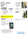
LIFT-505
BMF Lift Kit
Yamaha Drive
Gas or Electric
Installation Instructions
Contents of LIFT-505 Yamaha Drive BMF Lift Kit:
a
(1 ea.) BMF A-Arm Assembly
b
(1 ea.) Driver Side Shock Tower
c
(1 ea.) Passenger Side Shock Tower
d
(1 ea.) Driver Side Steering Knuckle
e
(1 ea.) Passenger Side Steering Knuckle
f
(1 ea.) Rear U-Bracket
g
(1 ea.) Connecting Rod Bracket
h
(2 ea.) Bags of Hardware (Contents on Next Page)
i
(1 ea.) Instructions
Page 12
Caution: Please read through the instructions carefully. Installer is responsible for damage if instructions are not followed properly. Look behind each
drill or cut location BEFORE YOU DRILL OR CUT. Installer is responsible for
damage (i.e. drilling/cutting into a wiring harness, battery, fuel tank etc.).
Extra installers will be helpful in some parts of the installation. Please refer
to all torqueing specifications on page 2 for installation.
Note: You must install larger tires and wheels once the cart is lifted. Stock
wheels will not work. We recommend a 22” tire with a minimum of a 10”
offset wheel for use on the RHOX BMF Lift Kit.
4. Adjust the tow-in by loosening the
jam nut then lengthen or shorten
the tie rod by turning the hex
shaped rod adjustment. Shortening
the tie rods increases the tow-in,
lengthening decreases it.
Contents of LIFT-505 Hardware Kit:
ITEM QTY. DESCRIPTION
TORQUE REQUIREMENTS
a.
1 ea. 12mm x 25 Hex Head Bolt
69.00 ft. lbs.
b.
1 ea. 12mm Nylock Nut
c.
4 ea. 10mm x 80 Hex Head Bolts
38.25 ft. lbs.
d.
6 ea. 10mm x 70 Hex Head Bolts
38.25 ft. lbs.
e.
2 ea. 10mm x 60 Hex Head Bolts
38.25 ft. lbs.
f.
12 ea. 10mm Nylock Nuts
g.
24 ea. 10mm Flat Washers
-------------------------------------------------------------
5. Once camber and tow adjustments are finalized and set, tighten all
hardware and jam nuts.
6. Reinstall the front bumper using the
Original Hardware.
NOTE: Cowl and body were removed for visibility purposes in the photos
shown. The BMF lift kit can be installed with the cowl and body installed.
Installation Preparation (Front of the Cart)
1. Make sure the parking brake is engaged and the key is in the off
position.
2. Electric Carts Only: If your cart has a Tow/Run Switch, place switch
in the Tow position.
3. Remove the hub caps (if any). Loosen lug nuts
on both front wheels. Do not remove lug nuts.
4. Chock the back of the rear wheels to prevent
the cart from moving.
5. Using a jack, safely lift the front end of the cart enough to accommodate the additional height of the larger tires and wheels.
6. Place jack stands securely under the chassis and remove jack.
7. Fully remove the (8) front lug nuts, front tires and wheels. Discard
the tires and wheels as they will not be reused.
Page 2
This completes the installation of your Yamaha Drive BMF Lift Kit.
Please enjoy safely!
Watch this installation and others on YouTube:
www.youtube.com/user/GolfCartInstructions
Page 11
Adjust the Tow-In and Camber
1. Drive forward and back 20-40 feet to check the tow-in and camber
before making adjustments. Only make adjustments if needed.
NOTE: For stability, an 1/8” tow-in with a positive camber is recommended. This will level out when the cart is loaded.
8. Remove the front bumper by removing the (2)
bolts holding it in place. Retain bumper and
hardware.
9. Disconnect the tie-rod ends from the steering
knuckles by removing the safety pin and nut
from the tie-rod end. Retain hardware.
10. Remove the steering knuckles from the spindles by removing the safety pins, nuts and
bolts. Discard steering knuckles and hardware.
11. Remove the shock assemblies by removing the bolts connecting
them to the cross frame and the A-arm. Retain shock assemblies
and hardware.
12. Remove and discard the A-arms. Retain hardware.
2. Adjust the camber by changing the mounting
position of the shock in the shock tower.
Mounting the shock to the outside of the cart
will make the camber more positive. Mounting it
to the inside of the cart will make the camber
more negative.
3. Calculate the tow-in of the
front tires by measuring the
center-to-center distance of
the front of the front tires
versus the center-to-center
distance of the back of the
front tires. The front
measurement should be
1/8” shorter than the rear.
Page 10
BMF Front Suspension Installation
NOTE: Please refer to page 2 for torqueing specifications for included
hardware. Please refer to vehicle’s maintenance manual for torqueing
specifications on reused hardware.
1. Identify the passenger side shock tower.
2. Insert the passenger side shock tower into the cross
frame as shown. Push the shock tower upward and
toward the cart; to the top of the cross frame.
Page 3
3. Align the hole in the shock tower with the hole
in the cross frame as indicated in yellow. If
needed, use a screwdriver to align the hole.
4. Insert the Original Bolt from the upper portion
of the shock into the aligned hole.
5. Insert a marking device through the thru holes
in the shock tower as shown. Mark a drill location on the side of the cross frame.
6. Remove the bolt and shock tower from the
cross frame.
7. Use a center punch and to mark the location of
the hole.
8. Wearing safety glasses, drill a 1/8”-3/16” pilot
hole through the cross frame at the marked location.
9. Drill a 13/32” hole through the pilot hole.
10. Reinsert the shock tower into the cross frame.
Align mounting holes.
11. Install the shock tower by using the Original Hardware from the upper portion of
the shock (yellow arrow) and (1) 10mm x
70 Hex Head Bolt, (2) 10mm Flat
Washers and (1) 10mm Nylock Nut (red
arrow).
12. Repeat Steps 1-11 for the driver side
shock tower.
13. Position the new BMF A-arm assembly in
front of the cart with the RHOX plate
facing forward.
14. Loosen the (4) bolts
on the mounting arms
of the A-arm assembly
for easier alignment.
15. Slightly spread the
mounting tabs on the
frame if needed for
installation.
Page 4
Head Bolt and (1) 12mm Nylock Nut (yellow arrow). Do not tighten.
15. Install the bracket to the chassis using (1) 10mm x 70 Hex Head
Bolt, (2) 10mm Flat Washers and (1) 10mm Nylock Nut (blue arrow).
16. Tighten both sets of hardware from steps 14 and 15.
NOTE: For matching bolt heads in the bagwell area, a second set of
10mm hardware is included in the BMF lift kit. Repeat steps 10-11
for the passenger side if desired. This will not effect the lift kit.
17. Reinstall the connecting rod to the new bracket and the original
mounting tab using the Original Hardware.
18. Tighten any hardware left loose in this section.
19. If the cart is not high enough to accommodate the larger tires and
wheels, raise the cart to the correct height with the jack.
20. Install the (2) rear tires/wheels on the rear hubs.
21. Remove the jack stands and lower the cart.
22. Remove the jack.
Page 9
6. Identify the U-bracket.
When oriented correctly, the
bracket will be angled
towards the front of the cart.
7. Slide the U-bracket into the
original shock mounts.
Install the U-bracket to the
shock mounts using (2)
10mm x 60 Hex Head Bolts,
(4) 10mm Flat Washers
and (2) 10mm Nylock Nuts.
8. Slowly raise the rear axle until the top of the shocks reach the new
shock mounts. Install the top of the shocks to the shock mounts
using the Original Hardware.
9. Reroute and reconnect any wires or cables removed in step 4. Use
wire ties to secure them if needed.
10. Locate the two bolts in the bagwell area. Remove the bolt on the
driver side.
11. Using the empty bolt hole as a guide, drill a 1/8” - 3/16” pilot hole
completely through the chassis. Then drill a 13/32” hole through
the pilot hole.
12. Orient the connecting rod bracket so the rounded corner is facing
downward and is closer to the driver side of the cart.
13. Place the connecting rod bracket on the underside of the chassis
and behind the original connecting rod mounting tab.
14. Install the bracket to the mounting tab using (1) 12mm x 25 Hex
Page 8
16. Using the Original Hardware,
bolt the new BMF A-arm
assembly to the chassis in the
(4) places where the original
A-arms were removed.
NOTE: Additional help is recommended during this step to help
support the A-arm assembly
during installation.
17. Tighten the hardware loosened in Step 14.
Keep the A-arm assembly aligned with the
frame.
18. Mount the shocks to the shock towers using
(1) 10mm x 70 Hex Head Bolt, (2) 10mm Flat
Washers and (1) 10mm Nylock Nut per shock.
It is recommended to install the shock in the
center hole position to start. If the camber
needs adjusting at the end of the installation,
the position can be changed.
19. Using the Original Hardware, mount the
bottom of the shocks to the BMF A-arms.
A rubber mallet can be used to align the
A-arm in the mounting tabs.
20. Attach the new passenger side steering
knuckle to the top of the spindle using (2)
10mm x 80 Hex Head Bolts, (4) 10mm
Flat Washers and (2) 10mm Nylock Nuts.
Torque the bolts to the correct torque
specifications shown on page 2.
21. Install the tie rod end to the steering knuckle using the Original
Hardware.
22. Repeat steps 20-21 for
the driver side steering
knuckle.
Page 5
23. Install the (2) front tires. The stock tires and
wheels will not work on the newly lifted cart.
Fully tighten the lug nuts on both wheels.
NOTE: It is recommended to use at least
22” tires on a 10” wheel with an offset. The
wheel shown is a RHOX Vegas TIR-RX160
with a RHOX Mojave II tire, TIR-265A.
BMF Rear Suspension Installation
Safety Note:
Proper eye and mouth protection should be worn during this section to
protect the installer from debris when working under the cart or drilling.
1. Carefully raise the jack to support
the rear axle.
24. Once the tire and wheels are fully secure, place the jack under the
cart. Remove jack stands and lower the cart safely to the ground.
Remove the chocks behind the rear wheels.
NOTE: The front bumper will remain off until the camber and tow
adjustments are made at the end of the installation.
2. Disconnect the rear connecting rod by removing the (2) bolts, nuts
and washers. Retain rod and hardware.
Installation Preparation (Rear of the Cart)
1. Turn the key to the off position and lock the parking brake.
2. Electric Carts Only: If your cart has a Tow/Run Switch, place switch
in the Tow position.
3. Chock the front of the front wheels to prevent the cart from moving.
4. Remove the rear access panel by
removing the rivets and unclipping it from
the body. Retain rivets.
5. Remove the hub caps (if any) on the rear
wheels. Loosen the lug nuts on both
wheels but do not remove the them.
6. Place a jack securely under the rear axle.
Safely lift the rear end of the cart enough
to accommodate the additional height of the
larger tires and wheels.
7. Place jack stands under the chassis on both
sides of the cart to stabilize it. Lower the jack
but do not remove it.
8. Fully remove the (8) rear lug nuts, rear tires and
wheels. Discard the tires and wheels as they
will not be reused.
3. Disconnect the top of the rear
shocks from the shock mounts.
Retain hardware.
4. Disconnect any wires or cables attached to
the motor that could be damaged when
lowering the rear suspension.
5. With the cart in the Tow position, slowly
and carefully lower the rear axle.
Safety Note: The electrical system could
be damaged if the cart is NOT in the Tow
position and a shock contacts the motor.
Page 6
Page 7