1
OB384--1.qxp 05.1.17 13:08 Page 1
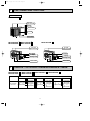
SPLIT-TYPE, AIR CONDITIONER
HFC
No. OB384
utilized
SERVICE MANUAL
R410A
Multi system type
Models
MUX-2A28VB
MUX-2A59VB
MUX-3A60VB
MUX-3A63VB
MUX-2A70VB
MUX-4A73VB
MUX-2A59VB
MUX-3A60VB
MUX-3A63VB
MUX-2A70VB
-
-
E1
E1
E1
E1
E1
E1
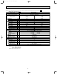
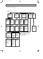
CONTENTS
E1
E1
E1
E1
Indication of
model name
NOTE:
•As for indoor unit MSC-CA20VB - E1 , MSC-CA25VB - E1
or MSC-CA35VB - E1 , refer to the service manual OB393.
•This manual describes technical data of outdoor unit.
•As for indoor unit MSC-GA20VB - E1 , MSC-GA25VB - E1
or MSC-GA35VB - E1 , refer to the service manual OB385.
1. TECHNICAL CHANGES ····································2
2. PART NAMES AND FUNCTIONS······················6
3. INDOOR / OUTDOOR
CORRESPONDENCE TABLE ···························6
4. SPECIFICATION·················································7
5. NOISE CRITERIA CURVES ·····························12
6. OUTLINES AND DIMENSIONS ······················ 13
7. WIRING DIAGRAM ··········································16
8. REFRIGERANT SYSTEM DIAGRAM ··············21
9. PERFORMANCE CURVES ······························32
10. ACTUATOR CONTROL····································55
11. TROUBLESHOOTING ······································56
12. DISASSEMBLY INSTRUCTIONS·····················63
13. PARTS LIST······················································68
OB384--1.qxp 05.1.17 13:08 Page 2
1
TECHNICAL CHANGES
MUX-A10WV- E1 ➔MUX-2A28VB- E1
MUX-A20WV- E1 ➔MUX-3A60VB- E1
1. Indication of capacity has been changed. (BTU➔kW)
MUX-A19WV- E1 ➔MUX-2A59VB- E1
MUX-A22WV- E1 ➔MUX-3A63VB- E1
MUX-A25WV- E1 ➔MUX-2A70VB- E1
MUX-A26WV- E1 ➔MUX-4A73VB- E1
1. Indication of capacity has been changed. (BTU➔kW)
2. Size of stop valve (Gas) has been changed. ([12.7➔[9.52)
2
OB384--1.qxp 05.1.17 13:08 Page 3
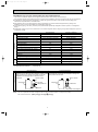
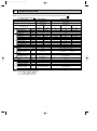
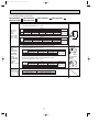
INFORMATION FOR THE AIR CONDITIONER WITH R410A REFRIGERANT
• This room air conditioner adopts HFC refrigerant (R410A) which never destroys the ozone layer.
• Pay particular attention to the following points, though the basic installation procedure is same as that for R22 conditioners.
1 As R410A has working pressure approximate 1.6 times as high as that of R22, some special tools and piping parts/
materials are required. Refer to the table below.
2 Take sufficient care not to allow water and other contaminations to enter the R410A refrigerant during storage and
installation, since it is more susceptible to contaminations than R22.
3 For refrigerant piping, use clean, pressure-proof parts/materials specifically designed for R410A. (Refer to 2. Refrigerant
piping.)
4 Composition change may occur in R410A since it is a mixed refrigerant. When charging, charge liquid refrigerant to prevent
composition change.
New refrigerant
R410A
R22
Composition (Ratio)
HFC-32: HFC-125 (50%:50%)
R22 (100%)
Refrigerant handling
Pseudo-azeotropic refrigerant
Single refrigerant
Not included
Included
Refrigerant
Chlorine
A1/A1
A1
72.6
86.5
Boiling point (:)
-51.4
-40.8
Steam pressure [25:](Mpa)
1.557
0.94
64
44.4
Non combustible
Non combustible
0
0.055
Refrigerant
Safety group (ASHRAE)
Molecular weight
Saturated steam density [25:](Kg/K)
Combustibility
ODP w1
GWP w2
Refrigerant charge method
1730
1700
From liquid phase in cylinder
Gas phase
Possible
Possible
Kind
Incompatible oil
Compatible oil
Color
Non
Light yellow
Non
Non
oil
Refrigeration
Additional charge on leakage
Smell
w1 :Ozone Destruction Parameter : based on CFC-11
w2 :Global Warmth Parameter
: based on CO2
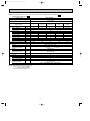
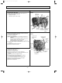
New Specification
Compressor
Previous refrigerant
Current Specification
The incompatible refrigeration oil easily separates from
Since refrigerant and refrigeration oil are compatible each,
refrigerant and is in the upper layer inside the suction muffler. refrigeration oil goes back to the compressor through the
Raising position of the oil back hole enables to back the
lower position oil back hole.
refrigeration oil of the upper layer to flow back to the
compressor.
Suction muffler
Suction muffler
Compressor
Oil back hole
Compressor
Refrigeration oil
Oil back hole
Refrigerant
Refrigeration oil /Refrigerant
NOTE : The unit of pressure has been changed to MPa on the international system of units(SI unit system).
f [Gauge])
The conversion factor is: 1(MPa [Gauge]) =10.2(kgf/f
3
OB384--1.qxp 05.1.17 13:08 Page 4
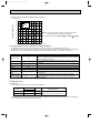
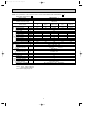
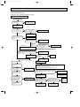
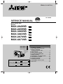
Conversion chart of refrigerant temperature and pressure
(MPa [Gauge])
4.0
Saturated liquid pressure
3.5
R410A
3.0
R22
2.5
2.0
NOTE : The unit of pressure has been changed to MPa on the
international system of units(SI unit system).
1.5
1.0
f [Gauge])
The conversion factor is: 1(MPa [Gauge]) =10.2(kgf/f
0.5
0.0
-0.5
-30 -20 -10
0
10
20
30
40
50
60
(:)
1.Tools dedicated for the air conditioner with R410A refrigerant
The following tools are required for R410A refrigerant. Some R22 tools can be substituted for R410A tools.
The diameter of the service port on the stop valve in outdoor unit has been changed to prevent any other refrigerant being
charged into the unit. Cap size has been changed from 7/16 UNF with 20 threads to 1/2 UNF with 20 threads.
R410A tools
Description
Can R22 tools be used?
Gauge manifold
No
Charge hose
No
Gas leak detector
Torque wrench
Yes
R410A has high pressures beyond the measurement range of existing
gauges. Port diameters have been changed to prevent any other refrigerant
from being charged into the unit.
Hose material and cap size have been changed to improve the pressure
resistance.
Dedicated for HFC refrigerant.
No
6.35 mm and 9.52 mm
Clamp bar hole has been enlarged to reinforce the spring strength in the tool.
Flare tool
Yes
Flare gauge
Vacuum pump
adapter
Electronic scale for
refrigerant charging
New
New
New
No : Not Substitutable for R410A
Provided for flaring work (to be used with R22 flare tool).
Provided to prevent the back flow of oil. This adapter enables you to use
vacuum pumps.
It is difficult to measure R410A with a charging cylinder because the
refrigerant bubbles due to high pressure and high-speed vaporization
Yes : Substitutable for R410A
2.Refrigerant piping
1 Specifications
Use the refrigerant pipes that meet the following specifications.
Outside diameter
mm
Wall
thickness
For liquid
6.35
0.8 mm
Heat resisting foam plastic
For gas
9.52
0.8 mm
Specific gravity 0.045 Thickness 8 mm
Pipe
Insulation material
• Use a copper pipe or a copper-alloy seamless pipe with a thickness of 0.8 mm. Never use any pipe with a thickness less
than 0.8mm, as the pressure resistance is insufficient.
4
OB384--1.qxp 05.1.17 13:08 Page 5
2 Flaring work and flare nut
Flaring work for R410A pipe differs from that for R22 pipe.
For details of flaring work, refer to Installation manual “FLARING WORK”.
Dimension of flare nut
Pipe diameter
mm
R410A
R22
6.35
17
17
9.52
22
22
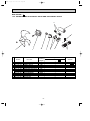
3.Refrigerant oil
Apply the special refrigeration oil (accessories: packed with indoor unit) to the flare and the union seat surfaces.
4.Air purge
• Do not discharge the refrigerant into the atmosphere.
Take care not to discharge refrigerant into the atmosphere during installation, reinstallation, or repairs to the refrigerant
circuit.
• Use the vacuum pump for air purging for the purpose of environmental protection.
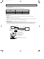
5.Additional charge
For additional charging, charge the refrigerant from liquid phase of the gas cylinder.
If the refrigerant is charged from the gas phase, composition change may occur in the refrigerant inside the cylinder and the
outdoor unit. In this case, ability of the refrigeration cycle decreases or normal operation can be impossible. However,
charging the liquid refrigerant all at once may cause the compressor to be locked. Thus, charge the refrigerant slowly.
Union
Stop valve
Indoor unit
Liquid pipe
Outdoor unit
Gas pipe
Refrigerant gas
cylinder
operating valve
Service port
Gauge manifold
valve (for R410A)
Charge hose (for R410A)
Refrigerant gas cylinder
for R410A with siphon
Refrigerant (liquid)
Electronic scale for refrigerant charging
5
OB384--1.qxp 05.1.17 13:08 Page 6
2
PART NAMES AND FUNCTIONS
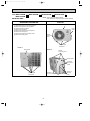
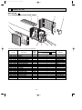
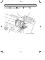
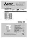
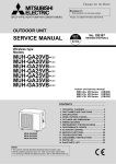
OUTDOOR UNIT
MUX-2A28VB- E1
Air inlet
(back and side)
Piping
Drain hose
Air outlet
Drain outlet
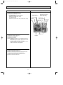
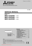
MUX-2A59VB- E1 MUX-3A63VB- E1
MUX-3A60VB- E1 MUX-2A70VB- E1
MUX-4A73VB- E1
Air inlet
(Back and side)
Air inlet
(Back and side)
Air outlet
Air outlet
Piping
Piping
Drainage hose
Drainage hose
Drain outlet
Drain outlet
3
INDOOR / OUTDOOR CORRESPONDENCE TABLE
MUX-2A28VB - E1
MUX-2A70VB - E1
MUX-2A59VB - E1
MUX-4A73VB - E1
MUX-3A60VB - E1
MUX-3A63VB - E1
OUTDOOR UNIT
MUX-2A28VB-
Combination of
the connectable
indoor units
E1
MUX-2A59VB-
A: MSC-CA35VBor
MSC-CA20VB- E1
MSC-GA35VBor
B: MSC-GA20VB- E1 B: MSC-CA20VBor
MSC-GA20VBA:
E1
MUX-3A60VB-
E1
E1
E1
E1
A: MSC-CA25VBB:
or
C: MSC-GA25VB-
E1
6
E1
E1
MUX-3A63VB-
E1
MUX-2A70VB-
E1
A: MSC-CA35VB- E1
or
A: MSC-CA35VB- E1
MSC-GA35VB- E1
or
B: MSC-CA20VB- E1 B: MSC-GA35VB- E1
or
C: MSC-GA20VB- E1
MUX-4A73VBA: MSC-CA35VBor
B: MSC-GA35VBC: MSC-CA25VBor
D: MSC-GA25VB-
E1
E1
E1
E1
E1
OB384--1.qxp 05.1.17 13:08 Page 7
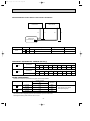
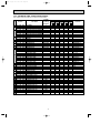
4
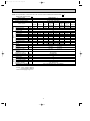
SPECIFICATION
NOTE: As for specification of the indoor units, refer to service manual OB393 (MSC-CA20/25/35VA- E1 ) or
OB385 (MSC-GA20/25/35VA- E1 ).
Outdoor model
MUX-2A59VB - E1
MUX-2A28VB - E1
Cooling
Cooling
Function
Single phase
Single phase
Outdoor unit power supply
230V,50Hz
230V,50Hz
Special
remarks
Fan
motor
Compressor
Capacity
Dehumidification
Outdoor air flow
Power outlet
Running current
Power input
Auxiliary heater
Power factor
Starting current
Compressor motor current
Fan motor current
kW
R/h
K /h
A
A
W
A(kW)
%
A
A
A
Coefficient of performance (C.O.P)
Model
Output
W
Winding
"
resistance (at 20:)
Model
Winding
"
resistance (at 20:)
Dimensions WOHOD
mm
Weight
kg
Sound level
dB
Fan speed
rpm
Fan speed regulator
Refrigerant filling
kg
capacity (R410A)
Refrigeration oil (Model)
cc
Electrical
data
Capacity
Indoor unit No.
Single
A or B
2.4
0.9
Double
A+B
1.4O2
0.2O2
1,914
10
3.20
725
3.25
730
—
98.5
97.7
21
2.91
2.96
0.29
3.16
3.50
RN092VHSHT
600
C-R 3.87
C-S 6.14
RA6V33-FC
WHT-BLK 223
BLK-RED 221
780O540O255
35
49
825
1
0.90 (Room A+B)
350 (NEO22)
NOTE: Test conditions are based on ISO 5151.
Cooling : Indoor DB27°C WB19°C
Outdoor DB35°C WB24°C
Indoor-Outdoor piping length : 5m
7
Single
A
3.5
1.4
Double
Single
A+B
B
3.5+2.4
2.4
1.4+0.9
0.9
2,460
20
5.73
8.96
3.51
1,280
2,005
785
—
97.2
97.1
97.3
48
2.94
5.16
8.39
0.57
2.93
2.65
2.84
MC1 : RN145VHSHT, MC2 : RN092VHSHT
MC1 : 1,000, MC2 : 600
C-R 3.87
C-R 2.43
MC1 :
, MC2 :
C-S 6.14
C-S 3.80
RA6V60-GA
WHT-BLK 90
BLK-RED 146
840O640O330
66
52
730
1
1.00 (Room A)
0.80 (Room B)
MC1 : 620 (NEO22), MC2 : 350 (NEO22)
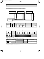
OB384--1.qxp 05.1.17 13:08 Page 8
Special
remarks
Fan
motor
Compressor
Electrical
data
Capacity
NOTE: As for specification of the indoor units, refer to service manual OB393 (MSC-CA20/25/35VA- E1 ) or
OB385 (MSC-GA20/25/35VA- E1 ).
Outdoor model
MUX-3A60VB - E1
Function
Cooling
Single phase
Outdoor unit power supply
230V,50Hz
Double
Single
Single
Double
Indoor unit No.
A+B or A+C
A
B or C
B+C
2.6+2.8
Capacity
2.6
2.9
1.75O2
kW
0.9+1.1
Dehumidification
0.9
1.2
0.3O2
R/h
2,460
Outdoor air flow
K /h
20
Power outlet
A
8.18
Running current
3.64
4.86
4.86
A
1,850
Power input
815
1,075
1,090
W
—
Auxiliary heater
A(kW)
98.3
Power factor
97.3
96.2
97.5
%
Starting current
47
A
Compressor motor current
3.07
4.29
4.29
7.61
A
Fan motor current
0.57
A
3.06
2.61
3.02
2.81
Coefficient of performance (C.O.P)
Model
MC1 : RN099VHSHT, MC2 : RN125VHSHT
Output
MC1 : 650, MC2 : 800
W
Winding
C-R 2.86
C-R 3.40
MC1 :
, MC2 :
"
resistance (at 20:)
C-S 5.72
C-S 4.56
RA6V60-GA
Model
Winding
WHT-BLK 90
"
resistance (at 20:)
BLK-RED 146
Dimensions WOHOD
840O640O330
mm
Weight
65
kg
Sound level
52
dB
Fan speed
730
rpm
Fan speed regulator
1
Refrigerant filling
0.80 (Room A)
kg
capacity (R410A)
1.00 (Room B+C)
MC1 : 350 (NEO22), MC2 : 350 (NEO22)
Refrigeration oil (Model)
cc
NOTE: Test conditions are based on ISO 5151.
Cooling : Indoor DB27°C WB19°C
Outdoor DB35°C WB24°C
Indoor-Outdoor piping length : 5m
8
Triple
A+B+C
2.5+1.75O2
0.8+0.3O2
8.41
1,885
97.5
7.84
3.02
OB384--1.qxp 05.1.17 13:08 Page 9
Special
remarks
Fan
motor
Compressor
Electrical
data
Capacity
NOTE: As for specification of the indoor units, refer to service manual OB393 (MSC-CA20/25/35VA- E1 ) or
OB385 (MSC-GA20/25/35VA- E1 ).
Outdoor model
MUX-3A63VB - E1
Cooling
Function
Single phase
Outdoor unit power supply
230V,50Hz
Double
Single
Single
Double
Indoor unit No.
A+B or A+C
A
B or C
B+C
3.5+2.4
3.5
2.4
1.45O2
Capacity
kW
1.4+0.9
1.4
0.9
0.4
Dehumidification
R/h
2,460
Outdoor air flow
K /h
Power outlet
20
A
5.73
3.64
3.69
Running current
8.92
A
1,280
815
830
Power input
1,975
W
Auxiliary heater
—
A(kW)
97.1
97.3
97.8
Power factor
96.3
%
Starting current
48
A
5.02
2.99
2.99
Compressor motor current
8.01
A
Fan motor current
0.57
A
2.65
2.82
3.22
2.88
Coefficient of performance (C.O.P)
Model
MC1 : RN145VHSHT, MC2 : RN092VHSHT
Output
MC1 : 1,000, MC2 : 600
W
Winding
C-R 3.87
C-R 2.43
MC1 :
, MC2 :
"
resistance (at 20:)
C-S 0.14
C-S 3.80
Model
RA6V60-GA
Winding
WHT-BLK 90
"
resistance (at 20:)
BLK-RED 146
Dimensions WOHOD
840O640O330
mm
Weight
67
kg
Sound level
52
dB
Fan speed
730
rpm
Fan speed regulator
1
Refrigerant filling
0.85 (Room A)
kg
capacity (R410A)
0.85 (Room B+C)
MC1 : 620 (NEO22), MC2 : 350 (NEO22)
Refrigeration oil (Model)
cc
NOTE: Test conditions are based on ISO 5151.
Cooling : Indoor DB27°C WB19°C
Outdoor DB35°C WB24°C
Indoor-Outdoor piping length 5m
9
Triple
A+B+C
3.4+1.45O2
1.4+0.4
8.84
1,980
97.4
8.01
3.01
OB384--1.qxp 05.1.17 13:08 Page 10
NOTE: As for specification of the indoor units, refer to service manual OB393 (MSC-CA20/25/35VAOB385 (MSC-GA20/25/35VA- E1 ).
Outdoor model
MUX-2A70VB - E1
Cooling
Function
Outdoor unit power supply
Single phase 230V,50Hz
Capacity
kW
Dehumidification
R/h
Outdoor air flow
K /h
Power outlet
A
Running current
A
Power input
W
Auxiliary heater
A(kW)
Power factor
%
Starting current
A
Compressor motor current
A
Fan motor current
A
Coefficient of performance (C.O.P)
Model
Output
W
Winding
"
resistance (at 20:)
Model
Winding
"
resistance (at 20:)
Dimensions WOHOD
mm
Weight
kg
Sound level
dB
Fan speed
rpm
Fan speed regulator
Refrigerant filling
kg
capacity (R410A)
Refrigeration oil (Model) cc
Special
remarks
Fan
motor
Compressor
Electrical
data
Capacity
Indoor unit No.
E1
) or
Single
A or B
Double
A+B
3.5
1.4
3.5O2
1.4O2
2,460
20
5.88
1,300
11.49
2,540
—
96.1
96.1
54
5.31
10.92
0.57
2.61
2.67
MC1 : RN145VHSHT, MC2 : RN145VHSHT
MC1 : 1,000, MC2 : 1,000
C-R 2.43
C-R 2.43
MC1 :
, MC2 :
C-S 3.80
C-S 3.80
RA6V60-GA
WHT-BLK 90
BLK-RED 146
840O640O330
68
52
730
1
0.95 (Room A)
0.95 (Room B)
MC1 : 620 (NEO22), MC2 : 620 (NEO22)
NOTE: Test conditions are based on ISO 5151.
Cooling : Indoor DB27°C WB19°C
Outdoor DB35°C WB24°C
Indoor-Outdoor piping length : 5m
10
OB384--1.qxp 05.1.17 13:08 Page 11
Special
remarks
Fan
motor
Compressor
Electrical
data
Capacity
NOTE: As for specification of the indoor units, refer to service manual OB393 (MSC-CA20/25/35VA- E1 ) or
OB385 (MSC-GA20/25/35VA- E1 ).
MUX-4A73VB - E1
Outdoor model
Cooling
Function
Single phase 230V,50Hz
Outdoor unit power supply
Triple
Double
Triple
Four
Single
Single
Double A+C or A+D Double
A+C+D
A+B+C
Indoor unit No.
or
or
or
C+D
A+B+C+D
A or B
C or D
A+B
B+C+D
B+C or B+D
A+B+D
3.4+2.7
3.4
2.75
1.7O2 1.95O2+2.8 3.4+1.7O2 1.95O2+1.7O2
1.95O2
kW
Capacity
1.2+1.1
1.2
1.1
0.3O2
0.2O2+1.1 1.2+0.3O2 0.2O2+0.3O2
0.2O2
R/h
Dehumidification
2,760
K /h
Outdoor air flow
20
A
Power outlet
9.57
5.28
4.54
4.78
9.61
9.66
9.75
5.46
A
Running current
2,095
1,180
1,015
1,060
2,105
2,140
2,210
1,210
W
Power input
—
A(kW)
Auxiliary heater
95.2
97.2
97.2
96.4
95.2
96.3
98.6
96.4
%
Power factor
52
A
Starting current
9.04
4.75
4.01
4.25
9.08
9.13
9.22
4.93
A
Compressor motor current
0.53
A
Fan motor current
2.81
2.79
2.62
3.01
3.02
3.02
3.09
3.02
Coefficient of performance (C.O.P)
MC1 : RN145VHSHT, MC2 : RN125VHSHT
Model
MC1 : 1,000, MC2 : 800
W
Output
Winding
C-R 2.86
C-R 2.43
"
MC1 :
, MC2 :
resistance (at 20:)
C-S 5.72
C-S 3.80
Model
RA6V60-FA
Winding
WHT-BLK 79
"
resistance (at 20:)
BLK-RED 80
mm
Dimensions WOHOD
840O850O330
76
kg
Weight
52
dB
Sound level
730
rpm
Fan speed
1
Fan speed regulator
1.05 (Room A+B)
Refrigerant filling
kg
1.05 (Room C+D)
capacity (R410A)
MC1 : 620 (NEO22), MC2 : 350 (NEO22)
Refrigeration oil (Model) cc
NOTE: Test conditions are based on ISO 5151.
Cooling : Indoor DB27°C WB19°C
Outdoor DB35°C WB24°C
Indoor-Outdoor piping length : 5m
11
OB384--1.qxp 05.1.17 13:08 Page 12
NOISE CRITERIA CURVES
MUX-2A28VB-
E1
FUNCTION
SPL(dB(A))
COOL
49
Test conditions.
Cooling : DB27:
90
MUX-2A59VB - E1
MUX-3A60VB - E1
MUX-3A63VB - E1
MUX-2A70VB - E1
LINE
WB19:
OCTAVE BAND SOUND PRESSURE LEVEL, dB re 0.0002 MICRO BAR
80
70
NC-70
60
NC-60
50
NC-50
40
NC-40
30
NC-30
20
52
WB24:
NC-70
60
NC-60
50
NC-50
40
NC-40
30
NC-30
APPROXIMATE
TERESHOLD OF
HEARING FOR
CONTINUOUS
NOISE
NC-20
10
63
125
250
500
1000
2000
4000
63
8000
MUX-4A73VB - E1
FUNCTION
SPL(dB(A))
COOL
52
Test conditions.
Cooling :DB35:
90
LINE
WB24:
80
70
NC-70
60
NC-60
50
NC-50
40
NC-40
30
NC-30
APPROXIMATE
TERESHOLD OF
HEARING FOR
CONTINUOUS
NOISE
NC-20
10
63
125
250
500
1000
2000
125
250
500
1000
2000
BAND CENTER FREQUENCIES, Hz
BAND CENTER FREQUENCIES, Hz
OCTAVE BAND SOUND PRESSURE LEVEL, dB re 0.0002 MICRO BAR
COOL
LINE
70
NC-20
10
20
SPL(dB(A))
80
20
APPROXIMATE
TERESHOLD OF
HEARING FOR
CONTINUOUS
NOISE
FUNCTION
Test conditions.
Cooling :DB35:
90
OCTAVE BAND SOUND PRESSURE LEVEL, dB re 0.0002 MICRO BAR
5
4000
8000
BAND CENTER FREQUENCIES, Hz
12
4000
8000
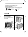
OB384--1.qxp 05.1.17 13:08 Page 13
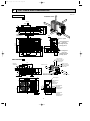
6
OUTLINES AND DIMENSIONS
Unit: mm
100mm or more
OUTDOOR UNIT
REQUIRED SPACE
MUX-2A28VB- E1
Air in
ore
m
00m
1
100
mm
320
or m
or m
255
285
320
109
32
ore
Air in
Drainage
3holes [33
147
ore
rm
mo
m
400
35
110
Air out
0m
m
25
or
mo
re
Service panel
10
122
500
780
40
10-
226
176
126
76
260
540
Liquid refrigerant
pipe joint
Refrigerant pipe
(flared) [6.35
120
56
MUX-2A59VB- E1
Gas refrigerant
pipe joint
Refrigerant pipe
(flared) [9.52
Open as a rule
500mm or more if
the front and both
sides are open
500
273
438
Air in
100mm or more
200mm or more if
there are obstacles
to both sides
100mm or more
Air in
100
360
330
34
Open as a rule
500mm or more if the back,
both sides and top are open
40
Air out
840
121
61
350mm or more
Service panel
65
80
264
13
76 50 5050
} B UNIT
} A UNIT
320
10°
640
Liquid refrigerant
pipe joint
Refrigerant pipe
(flared) {6.35
10°
125
30
Drainage
3holes {33
Gas refrigerant
pipe joint
Refrigerant pipe
(flared) {9.52
Gas refrigerant
pipe joint
Refrigerant pipe
(flared) {9.52
OB384--1.qxp 05.1.17 13:08 Page 14
Unit: mm
OUTDOOR UNIT
MUX-3A60VB- E1
MUX-3A63VB- E1
Open as a rule
500mm or more if
the front and both
sides are open
500
273
100mm or more
200mm or more if
there are obstacles
on both sides
100mm or more
438
Air in
Air in
360
330
34
125
30
Drainage
3 holes {33
Open as a rule
500mm or more if the back,
both sides and top are open
100
350mm or more
40
Air out
} C UNIT
} B UNIT
} A UNIT
76 50 505050 50
10°
Service panel
Liquid refrigerant
pipe joint
Refrigerant pipe
(flared) {6.35
320
10°
61
640
840
121
Gas refrigerant
pipe joint
Refrigerant pipe
(flared) {9.52
65
264
Open as a rule
500mm or more if
the front and both
sides are open
MUX-2A70VB- E1
500
273
100mm or more
200mm or more if
there are obstacles
on both sides
100mm or more
438
Air in
Air in
360
330
34
Open as a rule
500mm or more if the back,
both sides and top are open
100
350mm or more
40
Air out
840
121
61
} B UNIT
} A UNIT
264
80
14
76 50 5050
Liquid refrigerant
pipe joint
Refrigerant pipe
(flared) {6.35
320
10°
640
Service panel
10°
125
30
Drainage
3 holes {33
Gas refrigerant
pipe joint
Refrigerant pipe
(flared) {9.52
OB384--1.qxp 05.1.17 13:08 Page 15
OUTDOOR UNIT
MUX-4A73VB- E1
100mm or more
200mm or more if
there are obstacles
on both sides
40
30
34
438
273
Air in
100
100mm or more
360
330
125
Drainage
3 holes
{33
Open as a rule
500mm or more if
the front and both
sides are open
Air in
Air out 500
840
121
65
61
Open as a rule
500mm or more if the back,
both sides and top are open
350mm or more
Service panel
D Unit
C Unit
Gas refrigerant
pipe joint
Refrigerant pipe
(flared) {9.52
80
Gas refrigerant
pipe joint
Refrigerant pipe
(flared) {9.52
15
B Unit
A Unit
260
76 50 50 50 50 50 50 50
430
10°
10°
850
Liquid refrigerant
pipe joint
Refrigerant pipe
(flared) {6.35
Unit: mm
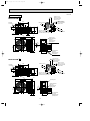
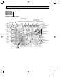
OB384--1.qxp 05.1.17 13:08 Page 16
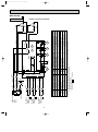
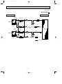
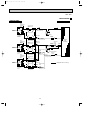
7
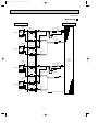
WIRING DIAGRAM
MUX-2A28VB - E1
MODEL WIRING DIAGRAM
TB1
1
2
1
WHT 1
TB3
BLU 2 BLU
1 BLU
21R1 BLU
BLU
21R2 BLU
2 BLU
BLU
1
X2
8
ORN
WHT
1 BLU
BLU 2
52C
BLU
C
C1 RED S MC
5 X1 1
3
6 X1 2
4
BRN
BRN
X1
8
BLK
YLW7
F62
F61
BLU
DSAR
TB2
WHT7
NAME
SYMBOL
BRN
BLU
2
WHT
WHT
BRN
CIRCUIT BREAKER
TO INDOOR
UNIT No.B
CONNECTING
12V
COM
N
PE
TO INDOOR
UNIT No.A
CONNECTING
12V
52C
NO
BRN
5 X2 1
BRN
L
3
6 X2 2
BRN
POWER SUPPLY
~/N
230V
50Hz
C2
OUTDOOR UNIT
R
BLK
WHT 1 WHT
BLU 2 BLK MF
RED 3 RED
4
BLU
WHT
2
BLU 1 BLU
2
TB3
SYMBOL
NAME
SYMBOL
MF
OUTDOOR FAN MOTOR(INNER FUSE)
21R
NAME
C1
COMPRESSOR CAPACITOR
21R1
SOLENOID COIL(A)
C2
OUTDOOR FAN CAPACITOR TB1,TB2,TB3 TERMINAL BLOCK
21R2
SOLENOID COIL(B)
SURGE ABSORBER
52C
COMPRESSOR CONTACTOR
DSAR
F61,F62 FUSE(2A)
MC
COMPRESSOR(INNER PROTECTOR)
X1
RELAY(A)
X2
RELAY(B)
21R
SOLENOID COIL
NOTE:1. About the indoor side electric wiring refer to the indoor unit electric wiring diagram for servicing.
2. Use copper conductors only. (For field wiring)
3. Symbols below indicate.
/: Terminal block,
: Connector
16
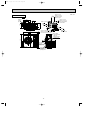
OB384--1.qxp 05.1.17 13:08 Page 17
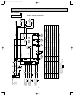
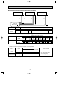
MUX-2A59VB - E1
MUX-2A70VB - E1
MODELS WIRING DIAGRAM
OUTDOOR UNIT
POWER SUPPLY TB1
L
~/N
230V
N
50Hz
2
BLU
1
ORN
BLU
X522
WHT
C2 RED
X521
S
BLK R MC2 C
WHT
2 3 4 5 6
C61
WHT
BLK
MF61
NAME
4
4
T61
CN91 1
SYMBOL
BRN
BRN
BRN
BLU
3
NR61
3
2
1
3
BLK R MC1 C
RED LD2
RED LD1
YLW
X521
X522
RED
1
3
2
1
F61
BLU
3 2 1 CN90 OUTDOOR CONTROL
P.C. BOARD
CN71
2 TB2
S
SR861
TO INDOOR
UNIT B
CONNECTING
12V
BRN
CN73
TO INDOOR
UNIT A
CONNECTING
12V
C1 RED
BLU
DSAR
CIRCUIT BREAKER
BLU 1
GRN/YLW
PE
TB4
BRN 2
SYMBOL
NAME
SYMBOL
TB1
NAME
C1
COMPRESSOR CAPACITOR(MC1)
MC1
COMPRESSOR(INNER PROTECTOR)
C2
COMPRESSOR CAPACITOR(MC2)
MC2
COMPRESSOR(INNER PROTECTOR) TB2~TB4 TERMINAL BLOCK
C61
OUTDOOR FAN CAPACITOR
MF61
OUTDOOR FAN MOTOR (INNER PROTECTOR)
SURGE ABSORBER
NR61
SURGE ABSORBER
X521
COMPRESSOR CONTACTOR(MC1)
FUSE(3.15A)
SR861
OUTDOOR FAN RELAY
X522
COMPRESSOR CONTACTOR(MC2)
DSAR
F61
NOTE:1. About the indoor side electric wiring refer to the indoor unit electric wiring diagram for servicing.
2. Use copper conductors only. (For field wiring)
3. Symbols below indicate.
/: Terminal block,
: Connector
17
T61
TERMINAL BLOCK
TRANSFORMER
TO INDOOR
UNIT C
CONNECTING
12V
TO INDOOR
UNIT A
CONNECTING
12V
TO INDOOR
UNIT B
CONNECTING
12V
18
3
2
WHT
1 CN91
COMPRESSOR(INNER PROTECTOR)
MC2
TB1
SR866
SR865
SR863
21RB
1 2 3
CN85
1 2 3
CN81
X522
4
SYMBOL
21R3
X521
4
1 2 3
CN86
3
21R4
NAME
SOLENOID COIL (B)
21R3
21R4
RELAY (B) (21R3)
TERMINAL BLOCK
SOLENOID COIL (C)
COMPRESSOR CONTACTOR(MC2)
SOLENOID COIL
X522
21RB
RELAY (C) (21R4)
RELAY (21RB)
TRANSFORMER
COMPRESSOR CONTACTOR(MC1)
T61
X521
OUTDOOR FAN RELAY
BLU
SURGE ABSORBER
OUTDOOR FAN MOTOR(INNER PROTECTOR) TB2~TB4 TERMINAL BLOCK
NAME
C61
T61
3
X522
X521
BLU
NOTE:1. About the indoor side electric wiring refer to the indoor unit electric wiring diagram for servicing.
2. Use copper conductors only. (For field wiring)
3. Symbols below indicate.
/: Terminal block,
: Connector
COMPRESSOR(INNER PROTECTOR)
MC1
SURGE ABSORBER
DSAR
FUSE(3.15A)
OUTDOOR FAN CAPACITOR
F61
NR61
COMPRESSOR CAPACITOR(MC2)
C2
C61
SR861
MF61
SYMBOL
NAME
MF61
1 2 3 4 5 6
COMPRESSOR CAPACITOR(MC1)
BLU
NR61
3 2 1 CN90 OUTDOOR CONTROL P.C. BOARD
BLU
C1
TB3
CN71
SYMBOL
1
2
1
3
2
1
3
2
ORN
1
BLU
BLU
2
GRN/YLW
YLW
TB2
DSAR
1
2
CIRCUIT BREAKER
BRN
WHT
BLK
PE
1
BRN
F61
SR861
BLU
RED
N
RED LD2
TB4
2
RED LD1
BRN
BLU
CN73
CN74
BRN
SR863
BLU
TB1
BLU
BRN
SR866
BLU
SR865
L
BLU
WHT
BLK R MC2 C
S
WHT
C2 RED
BLK R MC1 C
S
C1 RED
OUTDOOR UNIT
BLU
POWER SUPPLY
~/N
230V
50Hz
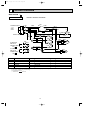
OB384--1.qxp 05.1.17 13:08 Page 18
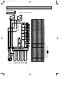
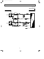
MUX-3A60VB - E1
MODEL WIRING DIAGRAM
TO INDOOR
UNIT C
CONNECTING
12V
TO INDOOR
UNIT A
CONNECTING
12V
TO INDOOR
UNIT B
CONNECTING
12V
19
COMPRESSOR(INNER PROTECTOR)
TB1
SR866
SR865
SR863
SR861
NR61
MF61
SYMBOL
MF61
1 2 3 4 5 6
NAME
21RB
1 2 3
CN85
1 2 3
CN81
X522
4
SYMBOL
21R3
X521
4
1 2 3
CN86
3
21R4
NAME
COMPRESSOR CONTACTOR(MC2)
SOLENOID COIL
SOLENOID COIL (B)
21RB
21R3
21R4
RELAY (B) (21R3)
TERMINAL BLOCK
SOLENOID COIL (C)
COMPRESSOR CONTACTOR(MC1)
X521
X522
OUTDOOR FAN RELAY
RELAY (C) (21R4)
S
C2 RED
WHT
WHT
BLK R MC2 C
TRANSFORMER
RELAY (21RB)
S
C1 RED
BLK R MC1 C
T61
BLU
SURGE ABSORBER
OUTDOOR FAN MOTOR(INNER PROTECTOR) TB2~TB4 TERMINAL BLOCK
C61
T61
3
X522
X521
BLU
NOTE:1. About the indoor side electric wiring refer to the indoor unit electric wiring diagram for servicing.
2. Use copper conductors only. (For field wiring)
3. Symbols below indicate.
/: Terminal block,
: Connector
COMPRESSOR(INNER PROTECTOR)
MC2
SURGE ABSORBER
DSAR
MC1
OUTDOOR FAN CAPACITOR
C61
FUSE(3.15A)
COMPRESSOR CAPACITOR(MC2)
C2
F61
COMPRESSOR CAPACITOR(MC1)
C1
3
2
WHT
1 CN91
BLU
NR61
3 2 1 CN90 OUTDOOR CONTROL P.C. BOARD
BLU
NAME
TB3
CN71
SYMBOL
1
2
1
3
2
1
3
2
ORN
1
BLU
BLU
2
GRN/YLW
YLW
TB2
DSAR
1
2
CIRCUIT BREAKER
BRN
WHT
BLK
PE
1
BRN
F61
SR861
BLU
RED
N
RED LD2
TB4
2
RED LD1
BRN
BLU
CN73
CN74
BRN
SR863
BLU
TB1
BLU
BRN
SR866
BLU
SR865
L
BLU
OUTDOOR UNIT
BLU
POWER SUPPLY
~/N
230V
50Hz
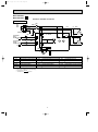
OB384--1.qxp 05.1.17 13:08 Page 19
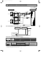
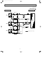
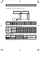
MUX-3A63VB - E1
MODEL WIRING DIAGRAM
20
2
CN86
2 3
SYMBOL
21R4
OUTDOOR FAN MOTOR(INNER PROTECTOR) TB1~TB4 TERMINAL BLOCK
TRANSFORMER
SURGE ABSORBER
T61
MF61
21R4
21R2
21R3
RELAY (A) (21R1)
SR868
COMPRESSOR(INNER PROTECTOR)
RELAY (B) (21R2)
SR867
COMPRESSOR(INNER PROTECTOR)
MC2
21R1
RELAY (C) (21R3)
MC1
21RB
RELAY (D) (21R4)
SR866
X522
21RA
SR865
NR61
21R3
1
RELAY (21RA)
FUSE(3.15A)
DSAR
CN85
2 3
RELAY (21RB)
SURGE ABSORBER
SR864
OUTDOOR FAN CAPACITOR
NAME
21R2
1
X521
21R1
CN84
2 3
X522
4
X522
3
OUTDOOR FAN RELAY
C61
1
CN83
2 3
1
T61
OUTDOOR CONTROL P.C. BOARD
BLU
BLU
F61
SR863
COMPRESSOR CAPACITOR(MC2)
C2
MF61
CN91 1 2 3 4 5 6
C61
1
SR861
YLW
1
3
1
SYMBOL
BLU
2
2
NAME
BRN
1
3
1
NR61
COMPRESSOR CAPACITOR(MC1)
BLU
2 TB3
2
3 2 1 CN90
C1
ORN
1
3
1
2
3
BLU
SYMBOL
BLU
BLU
2
GRN/YLW
WHT
DSAR
1
TB2
BLU 1
RED LD1
4
X521
3
X521
NAME
21RB
SOLENOID COIL (D)
SOLENOID COIL (C)
SOLENOID COIL (B)
SOLENOID COIL (A)
SOLENOID COIL (BALANCE)
COMPRESSOR CONTACTOR(MC2)
SOLENOID COIL (BALANCE)
COMPRESSOR CONTACTOR(MC1)
21RA
CN81
2 3
1
CN82
2 3
1
NOTE:1. About the indoor side electric wiring refer to the indoor unit electric wiring diagram for servicing.
2. Use copper conductors only. (For field wiring)
3. Symbols below indicate.
/: Terminal block,
: Connector
TO INDOOR
UNIT A
CONNECTING
12V
TO INDOOR
UNIT B
CONNECTING
12V
TO INDOOR
UNIT C
CONNECTING
12V
TO INDOOR
UNIT D
CONNECTING
12V
2
CIRCUIT BREAKER
BRN
CN74
CN73
CN72
CN71
BRN
F61
SR861
WHT
BLK
PE
BLU
N
RED
BRN
BLU
SR868
BLU
SR867
BLU
POWER SUPPLY
~/N
230V
50Hz
RED LD2
BRN
BLU
SR866
BLU
TB4
BLU
SR865
BLU
BRN 2
BLU
SR864
BLU
SR863
BLU
S
WHT
MC2 C
RED
WHT
BLK R
C2
S
MC1 C
RED
BLK R
C1
OUTDOOR UNIT
BLU
L TB1
OB384--1.qxp 05.1.17 13:08 Page 20
MUX-4A73VB - E1
MODEL WIRING DIAGRAM
OB384--1.qxp 05.1.17 13:08 Page 21
8
REFRIGERANT SYSTEM DIAGRAM
Unit : mm
MUX-2A28VB- E1
INDOOR UNIT
Room
temperature
thermistor
RT11
UNIT A
OUTDOOR UNIT
Solenoid
valve
Strainer 21R
#100
Refrigerant pipe
[9.52
(With insulation)
Indoor
heat
exchanger
Capillary tube
[3.0 x [1.4 x 1000
Stop valve
with service port
Muffler
Flared connection
Solenoid valve
21R1
Indoor coil
thermistor
RT12
Room
temperature
thermistor
RT11
UNIT B
Indoor
heat
exchanger
Refrigerant pipe
[6.35
(With insulation)
Stop
valve
Compressor
Strainer
#100
Capillary tube
[3.0 x [1.4 x 400
Outdoor
heat
exchanger
Capillary tube
[3.0 x [1.6 x 900
Refrigerant pipe
[9.52
(With insulation)
Stop valve
with service port
Flared connection
Solenoid valve
21R2
Indoor coil
thermistor
RT12
Refrigerant pipe
[6.35
(With insulation)
Stop
valve
Capillary tube
[3.0 x [1.4 x 400
Refrigerant flow in cooling
MAX. REFRIGERANT PIPING LENGTH & MAX. HEIGHT DIFFERENCE
Indoor unit A
Indoor unit B
Max. length
difference
10m
Outdoor unit
MUX-2A28VB- E1
Additional piping max. length 15m
ADDITIONAL REFRIGERANT CHARGE (R410A:g)
UNIT No.
A unit + B unit
Outdoor unit
precharged
900g
Refrigerant piping length (one way)
10 11 12 13 14 15 16 17 18 19 20 21 22 23 24 25 26 27 28 29 30
m m m m m m m m m m m m m m m m m m m m m
0 10 20 30 40 50 60 70 80 90 100 110 120 130 140 150 160 170 180 190 200
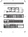
PIPING PREPARATION
1 Table below shows the specifications of pipes commercially available.
UNIT No.
A
and
B
UNIT
Pipe
For liquid
For gas
Outside diameter
mm
6.35
9.52
Insulation
thickness
8 mm
8 mm
2 Ensure that the 2 refrigerant pipes are well insulated to prevent condensation.
3 Refrigerant bending radius must be 10cm or more.
21
Insulation material
Heat resisting foam plastic
0.045 specific gravity
OB384--1.qxp 05.1.17 13:08 Page 22
Unit : mm
MUX-2A59VB- E1
INDOOR UNIT
OUTDOOR UNIT
Room
temperature
thermistor
RT11
UNIT A
Refrigerant pipe
[9.52
(With insulation)
Indoor
heat
exchanger
Stop valve
with service port
Muffler
Flared connection
Indoor coil
thermistor
RT12
Room
temperature
thermistor
RT11
UNIT B
Indoor
heat
exchanger
Compressor(A)
Stop valve
Refrigerant pipe
[6.35
(With insulation)
Capillary tube
Strainer
#100
[3.0 x [1.4 x 850
Refrigerant pipe
[9.52
(With insulation)
Flared connection
Outdoor
heat
exchanger
Muffler
Stop valve
with
service port
Compressor(B)
Indoor coil
thermistor
RT12
Refrigerant pipe
[6.35
(With insulation)
Stop valve
Capillary tube
[3.0 x [1.4 x 1100
Strainer
#100
Refrigerant flow in cooling
22
OB384--1.qxp 05.1.17 13:08 Page 23
MAX.REFRIGERANT PIPING LENGTH & MAX. HEIGHT DIFFERENCE
Indoor unit B
Indoor unit A
LA
H
H
LB
Outdoor unit
MUX-2A59VB - E1
UNIT No.
Max.
limits
Pipe length
Height difference (H)
No. of bends
A
LA
15m
10m
10
B
LB
15m
10m
10
ADDITIONAL REFRIGERANT CHARGE (R410A:g)
A unit
B unit
Refrigerant piping length (one way)
Outdoor unit
precharged
7m
8m
9m
10m
11m
12m
13m
14m
15m
1000g
0
20
40
60
80
100
120
140
160
Refrigerant piping length (one way,2 unit total)
Outdoor unit
precharged
7m
8m
9m
10m
11m
12m
13m
14m
15m
800g
0
20
40
60
80
100
120
140
160
PIPING PREPARATION
1Table below shows the specifications of pipes commercially available.
Outside diameter
UNIT No.
A unit
B unit
mm
Insulation
thickness
For liquid
6.35
8mm
For gas
9.52
8mm
For liquid
6.35
8mm
For gas
9.52
8mm
Pipe
2Ensure that the 2 refrigerant pipes are well insulated to prevent condensation.
3Refrigerant bending radius must be 10cm or more.
23
Insulation material
Heat resisting foam plastic
0.045 specific gravity
OB384--1.qxp 05.1.17 13:08 Page 24
Unit : mm
MUX-3A60VB- E1
INDOOR UNIT
OUTDOOR UNIT
Room
temperature
thermistor
RT11
UNIT A
Refrigerant pipe
[9.52
(With insulation)
Indoor
heat
exchanger
Muffler
Stop valve
with service port
Flared connection
Indoor coil
thermistor
RT12
Room
temperature
thermistor
RT11
UNIT B
Indoor
heat
exchanger
Refrigerant pipe
[6.35
(With insulation)
Refrigerant pipe
[9.52
(With insulation)
Capillary tube
[3.0 x [1.4 x 950
Stop valve
with
service port
UNIT C
Indoor
heat
exchanger
Solenoid
Strainer valve
21RB
#100
Outdoor
heat
exchanger
Muffler
Capillary tube
Flared connection
Solenoid valve
21R3
Compressor(B,C)
Refrigerant pipe
[6.35
(With insulation)
Capillary tube
[3.0 x [1.6 x 900
Capillary tube Strainer
#100
[3.0 x [1.6 x 900
Refrigerant pipe
[9.52
(With insulation)
Flared connection
Stop valve
with
service port
Stop
valve
Indoor coil
thermistor
RT12
Strainer
#100
[3.0 x [1.4 x 1000
Stop
valve
Indoor coil
thermistor
RT12
Room
temperature
thermistor
RT11
Compressor(A)
Stop valve
Refrigerant pipe
[6.35
(With insulation)
Solenoid valve
21R4
Capillary tube
[3.0 x [1.6 x 900
24
Refrigerant flow in cooling
OB384--1.qxp 05.1.17 13:08 Page 25
MAX.REFRIGERANT PIPING LENGTH & MAX. HEIGHT DIFFERENCE
Indoor unit C
Indoor unit B
Indoor unit A
H
LA
LB
H
LC
H
Outdoor unit
MUX-3A60VB - E1
Pipe length
UNIT No.
Max.
limits
A
LA
B
LB
C
LC
Height difference (H)
No. of bends
10m
10
15m
15m
LB
15m
+
LC
Total
30m
10m
10
10m
10
Total
15
ADDITIONAL REFRIGERANT CHARGE (R410A:g)
A unit
B unit + C unit
Refrigerant piping length (one way)
Outdoor unit
precharged
7m
8m
9m
10m
11m
12m
13m
14m
15m
800g
0
20
40
50
80
100
120
140
160
Refrigerant piping length (one way, 2 unit total)
Outdoor unit
precharged 10 11 12 13 14 15 16 17 18 19 20 21 22 23 24 25 26 28 27 29 30
m m m m m m m m m m m m m m m m m m m m m
1000g
0 10 20 30 40 50 60 70 80 90 100 110 120 130 140 150 160 180 170 190 200
PIPING PREPARATION
1Table below shows the specifications of pipes commercially available.
Outside diameter
UNIT No.
mm
Insulation
thickness
Pipe
A , B and
For liquid
6.35
8mm
C unit
For gas
9.52
8mm
2Ensure that the 2 refrigerant pipes are well insulated to prevent condensation.
3Refrigerant bending radius must be 100mm or more.
25
Insulation material
Heat resisting foam plastic
0.045 specific gravity
OB384--1.qxp 05.1.17 13:08 Page 26
Unit : mm
MUX-3A63VB- E1
INDOOR UNIT
OUTDOOR UNIT
Room
temperature
thermistor
RT11
UNIT A
Refrigerant pipe
[9.52
(With insulation)
Indoor
heat
exchanger
Muffler
Stop valve
with service port
Flared connection
Indoor coil
thermistor
RT12
Room
temperature
thermistor
RT11
UNIT B
Indoor
heat
exchanger
Capillary tube
Refrigerant pipe
[6.35
(With insulation)
Refrigerant pipe
[9.52
(With insulation)
[3.0 x [1.6 x 900
Stop valve
with
service port
UNIT C
Solenoid
valve
Strainer 21RB
#100
Muffler
[3.0 x [1.4 x 1000
Flared connection
Solenoid valve
21R3
Compressor(B,C)
Refrigerant pipe
[6.35
(With insulation)
Strainer
#100
Capillary tube
[3.0 x [1.6 x 900
Capillary tube
[3.0 x [1.6 x700
Refrigerant pipe
[9.52
(With insulation)
Indoor
heat
exchanger
Stop valve
with
service port
Flared connection
Stop
valve
Indoor coil
thermistor
RT12
Outdoor
heat
exchanger
Capillary tube
Stop
valve
Indoor coil
thermistor
RT12
Room
temperature
thermistor
RT11
Compressor(A)
Strainer
#100
Stop valve
Refrigerant pipe
[6.35
(With insulation)
Solenoid valve
21R4
Capillary tube
[3.0 x [1.6 x 900
26
Refrigerant flow in cooling
OB384--1.qxp 05.1.17 13:08 Page 27
MAX.REFRIGERANT PIPING LENGTH & MAX. HEIGHT DIFFERENCE
Indoor unit A
Indoor unit B
LA
H
Indoor unit C
H
LB
LC
H
Outdoor unit
MUX-3A63VB - E1
UNIT No.
Max.
limits
Pipe length
Unit A
LA
Unit B
LB
Unit C
Height difference (H)
No. of bends
10m
10
15m
LC
15m
LB
15m
+
LC
Total
30m
10m
10
10m
10
Total
15
ADDITIONAL REFRIGERANT CHARGE (R410A:g)
Unit A
Unit B + Unit C
Refrigerant piping length (one way)
Outdoor unit
precharged
7m
8m
9m
10m
11m
12m
13m
14m
15m
850g
0
20
40
60
80
100
120
140
160
Refrigerant piping length (one way, 2 unit total)
Outdoor unit
precharged 10 11 12 13 14 15 16 17 18 19 20 21 22 23 24 25 26 27 28 29 30
m m m m m m m m m m m m m m m m m m m m m
850g
0 10 20 30 40 50 60 70 80 90 100 110 120 130 140 150 160 170 180 190 200
PIPING PREPARATION
1Table below shows the specifications of pipes commercially available.
Outside diameter
UNIT No.
mm
Insulation
thickness
For liquid
6.35
8mm
For gas
9.52
8mm
For liquid
6.35
8mm
For gas
9.52
8mm
Pipe
Insulation material
Unit A
Unit B and Unit C
2Ensure that the 2 refrigerant pipes are well insulated to prevent condensation.
3Refrigerant bending radius must be 100mm or more.
27
Heat resisting foam plastic
0.045 specific gravity
OB384--1.qxp 05.1.17 13:08 Page 28
Unit : mm
MUX-2A70VB- E1
INDOOR UNIT
OUTDOOR UNIT
Room
temperature
thermistor
RT11
UNIT A
Refrigerant pipe
[9.52
(With insulation)
Indoor
heat
exchanger
Stop valve
with service port
Muffler
Flared connection
Indoor coil
thermistor
RT12
Room
temperature
thermistor
RT11
UNIT B
Indoor
heat
exchanger
Compressor(A)
Stop valve
Refrigerant pipe
[6.35
(With insulation)
Capillary tube
Strainer
#100
[3.0 x [1.4 x 700
Refrigerant pipe
[9.52
(With insulation)
Flared connection
Outdoor
heat
exchanger
Muffler
Stop valve
with
service port
Compressor(B)
Indoor coil
thermistor
RT12
Refrigerant pipe
[6.35
(With insulation)
Stop valve
Capillary tube
[3.0 x [1.4 x 700
Strainer
#100
Refrigerant flow in cooling
28
OB384--1.qxp 05.1.17 13:08 Page 29
MAX.REFRIGERANT PIPING LENGTH & MAX. HEIGHT DIFFERENCE
Indoor unit B
Indoor unit A
LA
H
H
LB
Outdoor unit
MUX-2A70VB - E1
UNIT No.
Max.
limits
Pipe length
Height difference (H)
No. of bends
A
LA
15m
10m
10
B
LB
15m
10m
10
ADDITIONAL REFRIGERANT CHARGE (R410A:g)
A unit
B unit
Refrigerant piping length (one way)
Outdoor unit
precharged
7m
8m
9m
10m
11m
12m
13m
14m
15m
950g
0
20
40
60
80
100
120
140
160
Refrigerant piping length (one way)
Outdoor unit
precharged
7m
8m
9m
10m
11m
12m
13m
14m
15m
950g
0
20
40
60
80
100
120
140
160
PIPING PREPARATION
1Table below shows the specifications of pipes commercially available.
Outside diameter
UNIT No.
A and B unit
mm
Insulation
thickness
For liquid
6.35
8mm
For gas
9.52
8mm
Pipe
2Ensure that the 2 refrigerant pipes are well insulated to prevent condensation.
3Refrigerant bending radius must be 10cm or more.
29
Insulation material
Heat resisting foam plastic
0.045 specific gravity
OB384--1.qxp 05.1.17 13:08 Page 30
Unit : mm
MUX-4A73VB- E1
INDOOR UNIT
Room
temperature
thermistor
RT11
UNIT A
OUTDOOR UNIT
Refrigerant pipe
{9.52
(With insulation)
Indoor
heat
exchanger
Strainer
#100
Stop valve
with service port
Solenoid
valve
21RA
Capillary tube
[3.0 x [1.4 x 1000
Muffler
Flared connection
Solenoid valve
21R1
Indoor coil
thermistor
RT12
Room
temperature
thermistor
RT11
UNIT B
Refrigerant pipe
{6.35
(With insulation)
Stop
valve
Compressor 1
Strainer
#100
Capillary tube
[3.0 x [1.8 x 700
Capillary tube
[3.0 x [2.0 x 700
Refrigerant pipe
{9.52
(With insulation)
Indoor
heat
exchanger
Stop valve
with service port
Flared connection
Solenoid valve
21R2
Indoor coil
thermistor
RT12
Room
temperature
thermistor
RT11
UNIT C
Refrigerant pipe
{6.35
(With insulation)
Stop
valve
Capillary tube
[3.0 x [1.8 x 700
Outdoor
heat
exchanger
Refrigerant pipe
{9.52
(With insulation)
Indoor
heat
exchanger
Strainer
#100
Stop valve
with service port
Solenoid
valve
21RB
Capillary tube
[3.0 x [1.4 x 1000
Muffler
Flared connection
Solenoid valve
21R3
Indoor coil
thermistor
RT12
Room
temperature
thermistor
RT11
UNIT D
Refrigerant pipe
{6.35
(With insulation)
Stop
valve
Capillary tube
[3.0 x [1.6 x 600
Capillary tube
Strainer
#100
[3.0 x [1.8 x 800
Refrigerant pipe
{9.52
(With insulation)
Indoor
heat
exchanger
Compressor 2
Stop valve
with service port
Flared connection
Solenoid valve
21R4
Indoor coil
thermistor
RT12
Refrigerant pipe
{6.35
(With insulation)
Stop
valve
Capillary tube
[3.0 x [1.6 x 600
Refrigerant flow in cooling
30
OB384--2.qxp 05.1.17 13:09 Page 31
MAX.REFRIGERANT PIPING LENGTH & MAX. HEIGHT DIFFERENCE
Indoor unit A
LA
Indoor unit B
H
Indoor unit C
LB
H
LC
Indoor unit D
H
LD
H
Outdoor unit
MUX-4A73VB- E1
Pipe length
UNIT No.
Max.
limits
A
LA
B
LB
Height difference (H)
LA
15m
+
C
LC
D
LD
15m
LB
15m
LC
+
15m
LD
No. of bends
Total
30m
10m
10
10m
10
Total
30m
10m
10
10m
10
Total
15
Total
15
ADDITIONAL REFRIGERANT CHARGE (R410A:g)
UNIT No.
Outdoor unit
precharged
Refrigerant piping length (one way, 2 unit total)
10 11 12 13 14 15 16 17 18 19 20 21 22 23 24 25 26 27 28 29 30
m m m m m m m m m m m m m m m m m m m m m
A unit + B unit
1050g
0
10 20 30 40 50 60 70 80 90 100 110 120 130 140 150 160 170 180 190 200
C unit + D unit
1050g
0
10 20 30 40 50 60 70 80 90 100 110 120 130 140 150 160 170 180 190 200
PIPING PREPARATION
1Table below shows the specifications of pipes commercially available.
Outside diameter
UNIT No.
A and B unit
C and D unit
mm
Insulation
thickness
For liquid
6.35
8mm
For gas
9.52
8mm
For liquid
6.35
8mm
For gas
9.52
8mm
Pipe
2Ensure that the 2 refrigerant pipes are well insulated to prevent condensation.
3Refrigerant bending radius must be 10cm or more.
31
Insulation material
Heat resisting foam plastic
0.045 specific gravity
OB384--2.qxp 05.1.17 13:09 Page 32
9
PERFORMANCE CURVES
MUX-2A28VB - E1 MUX-3A63VB - E1
MUX-2A59VB - E1 MUX-2A70VB - E1
MUX-3A60VB - E1 MUX-4A73VB - E1
The standard data contained in these specifications apply only to the operation of the air conditioner under normal conditions,
since operating conditions vary according to the areas where these units are installed. The following information has been provided to clarify the operating characteristics of the air conditioner under the conditions indicated by the performance curve.
(1) GUARANTEED VOLTAGE
198~264V, 50Hz
(2) AIR FLOW
Air flow should be set at MAX.
(3) MAIN READINGS
(1) Indoor intake air wet-bulb temperature :
(2) Indoor outlet air wet-bulb temperature :
(3) Outdoor intake air dry-bulb temperature :
(4) Total input:
°CWB
°CWB
°CDB
W
Indoor air wet/dry-bulb temperature difference on the left side of the chart on the next page shows the difference between
the indoor intake air wet/dry-bulb temperature and the indoor outlet air wet/dry-bulb temperature for your reference at service.
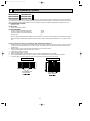
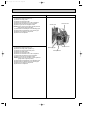
How to measure the indoor air wet-bulb/dry-bulb temperature difference
1.
2.
3.
4.
5.
6.
7.
Attach at least 2 sets of wet-and dry-bulb thermometers to the indoor air intake as shown in the figure, and at least 2 sets
of wet-and dry-bulb thermometers to the indoor air outlet. The thermometers must be attached to the position where air
speed is high.
Attach at least 2 sets of wet-and dry-bulb thermometers to the outdoor air intake.
Cover the thermometers to prevent direct rays of the sun.
Check that the air filter is cleaned.
Open windows and doors of room.
Press the EMERGENCY OPERATION switch once to start the EMERGENCY COOL MODE.
When system stabilizes after more than 15 minutes, measure temperature and take an average temperature.
10 minutes later, measure temperature again and check that the temperature does not change.
INDOOR UNIT
OUTDOOR UNIT
Wet-and dry-bulb
thermometers
Wet-and dry-bulb
thermometers
32
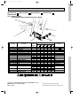
OB384--2.qxp 05.1.17 13:09 Page 33
10.2
10.3
8.6
9.4
9.4
9.4
8.5
7.8
8.5
8.5
8.6
7.7
7.1
7.7
7.7
7.7
6.9
6.3
6.9
6.9
6.9
6.1
6.1
6.2
MUX-2A70VB- E1
(Indoor unit A or B)
MUX-4A73VB- E1
(Indoor unit A or B)
9.4
8.6
8.7
9.9
9.4
7.8
8.5
7.8
7.9
9.0
7.1
7.7
7.1
7.1
8.1
6.3
6.9
6.3
6.4
7.3
5.6
6.1
5.6
5.7
6.4
6.1
5.6
MUX-3A63VB- E1
(Indoor unit B or C)
8.6
MUX-3A63VB- E1
(Indoor unit A)
10.2
MUX-3A60VB- E1
(Indoor unit B or C)
10.8
MUX-3A60VB- E1
(Indoor unit A)
9.5
MUX-2A59VB- E1
(Indoor unit B)
9.4
MUX-2A59VB- E1
(Indoor unit A)
10.2
MUX-4A73VB- E1
(Indoor unit C or D)
9.4 10.2
9.4
MUX-2A28VB- E1
(Indoor unit A or B)
Indoor air WB temperature
difference (deg.)
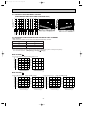
9-1.CAPACITY AND THE INPUT CURVES
(ONE INDOOR UNIT WITH ONE OUTDOOR UNIT)
9-2.OUTDOOR LOW PRESSURE AND OUTDOOR UNIT CURRENT
COOL operation
① Both indoor and outdoor unit are under same temperature/humidity condition.
➁
③
Dry-bulb temperature
Relative humidity (%)
20
50
25
60
30
70
Air flow should be set at MAX.
The unit of pressure has been changed to MPa on the international system of units(SI unit system).
f[Gauge] )
The conversion factor is : 1(MPa[Gauge]) =10.2(kgf/f
MUX-2A28VB- E1
12 1.2
11 1.1
10 1.0
230V
9 0.9
8 0.8
7 0.7
Outdoor unit current (A)
Outdoor low pressure (kgf/F[Gauge])
(kgf/F[Gauge])(MPa[Gauge]) Single operation (Unit A or B)
1.3
4.0
13
25
30
(˚C)
20
60
70
(%)
50
Ambient temperature(˚C)
Ambient humidity(%)
3.5
3.0
230V
2.5
2.0
25
30
(˚C)
20
60
70
(%)
50
Ambient temperature(˚C)
Ambient humidity(%) ˚C)
(%)
MUX-2A59VB- E1
9 0.9
8 0.8
7 0.7
6 0.6
230V
25
30
(˚C)
20
60
70
(%)
50
Ambient temperature(˚C)
Ambient humidity(%)
6.0
5.0
230V
4.0
3.0
25
30
(˚C)
20
60
70
(%)
50
Ambient temperature(˚C)
Ambient humidity(%)
33
Single operation (Unit B)
4.0
12 1.2
11 1.1
10 1.0
9 0.9
8 0.8
7 0.7
230V
Outdoor unit current (A)
10 1.0
7.0
Outdoor low pressure (kgf/F[Gauge])
11 1.1
(kgf/F[Gauge])(MPa[Gauge])
1.3
13
Single operation (Unit A)
Outdoor unit current (A)
Outdoor low pressure (kgf/F[Gauge])
(kgf/F[Gauge])(MPa[Gauge])
1.2
12
25
30
(˚C)
20
60
70
(%)
50
Ambient temperature(˚C)
Ambient humidity(%)
3.5
3.0
230V
2.5
2.0
25
30
(˚C)
20
60
70
(%)
50
Ambient temperature(˚C)
Ambient humidity(%)
OB384--2.qxp 05.1.17 13:09 Page 34
MUX-3A60VB- E1
10 1.0
230V
8 0.8
7 0.7
6 0.6
25
30
(˚C)
20
60
70
(%)
50
Ambient temperature(˚C)
Ambient humidity(%)
Outdoor low pressure (kgf/F[Gauge])
11 1.1
9 0.9
(kgf/F[Gauge])(MPa[Gauge]) Single operation (Unit B or C)
0.9
6.0
9
5.0
4.0
230V
3.0
2.0
25
30
(˚C)
20
60
70
(%)
50
Ambient temperature(˚C)
Ambient humidity(%)
8 0.8
7 0.7
230V
6 0.6
5 0.5
4 0.4
Outdoor unit current (A)
Single operation (Unit A)
Outdoor unit current (A)
Outdoor low pressure (kgf/F[Gauge])
(kgf/F[Gauge])(MPa[Gauge])
1.2
12
5.0
4.0
3.0
25
30
(˚C)
20
60
70
(%)
50
Ambient temperature(˚C)
Ambient humidity(%)
230V
25
30
(˚C)
20
60
70
(%)
50
Ambient temperature(˚C)
Ambient humidity(%)
MUX-3A63VB- E1
Single operation (Unit A)
9 0.9
230V
7 0.7
6 0.6
25
30
(˚C)
20
60
70
(%)
50
Ambient temperature(˚C)
Ambient humidity(%)
6.0
230V
5.0
4.0
25
30
(˚C)
20
60
70
(%)
50
Ambient temperature(˚C)
Ambient humidity(%)
12 1.2
3.5
11 1.1
3.0
10 1.0
230V
9 0.9
230V
2.5
8 0.8
7 0.7
Outdoor unit current (A)
10 1.0
Outdoor low pressure (kgf/F[Gauge])
11 1.1
8 0.8
(kgf/F[Gauge])(MPa[Gauge])Single operation (Unit B or C)
4.0
1.3
13
7.0
Outdoor unit current (A)
Outdoor low pressure (kgf/F[Gauge])
(kgf/F[Gauge])(MPa[Gauge])
1.2
12
25
30
(˚C)
20
60
70
(%)
50
Ambient temperature(˚C)
Ambient humidity(%)
2.0
25
30
(˚C)
20
60
70
(%)
50
Ambient temperature(˚C)
Ambient humidity(%)
MUX-2A70VB- E1
11 1.1
10 1.0
9 0.9
230V
8 0.8
7 0.7
6 0.6
Outdoor unit current (A)
Outdoor low pressure (kgf/F[Gauge])
(kgf/F[Gauge])(MPa[Gauge]) Single operation (Unit A or B)
1.2
7.0
12
25
30
(˚C)
20
60
70
(%)
50
Ambient temperature(˚C)
Ambient humidity(%)
6.0
230V
5.0
4.0
25
30
(˚C)
20
60
70
(%)
50
Ambient temperature(˚C)
Ambient humidity(%)
MUX-4A73VB- E1
230V
8 0.8
7 0.7
6 0.6
25
30
(˚C)
20
60
70
(%)
50
Ambient temperature(˚C)
Ambient humidity(%)
5.0
230V
4.0
3.0
25
30
(˚C)
20
60
70
(%)
50
Ambient temperature(˚C)
Ambient humidity(%)
34
10 1.0
9 0.9
230V
8 0.8
7 0.7
6 0.6
Outdoor unit current (A)
9 0.9
(kgf/F[Gauge])(MPa[Gauge])Single operation (Unit C or D)
5.0
1.1
11
Outdoor low pressure (kgf/F[Gauge])
10 1.0
Outdoor unit current (A)
Outdoor low pressure (kgf/F[Gauge])
(kgf/F[Gauge])(MPa[Gauge]) Single operation (Unit A or B)
6.0
1.1
11
25
30
(˚C)
20
60
70
(%)
50
Ambient temperature(˚C)
Ambient humidity(%)
4.0
230V
3.0
2.0
25
30
(˚C)
20
60
70
(%)
50
Ambient temperature(˚C)
Ambient humidity(%)
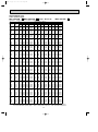
OB384--2.qxp 05.1.17 13:09 Page 35
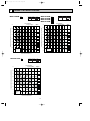
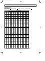
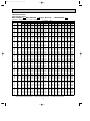
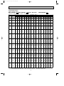
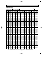
PERFORMANCE DATA
COOL operation (230V)
MSC-CA20VB - E1
MSC-GA20VB - E1 (Single) : MUX-2A28VB - E1
CAPACITY : 2.4(kW) SHF : 0.74 INPUT : 760(W)
INDOOR INDOOR
DB(:) WB(:)
21
21
22
22
22
23
23
23
24
24
24
24
25
25
25
25
26
26
26
26
26
27
27
27
27
27
28
28
28
28
28
29
29
29
29
29
30
30
30
30
30
31
31
31
31
31
32
32
32
32
32
NOTE
18
20
18
20
22
18
20
22
18
20
22
24
18
20
22
24
18
20
22
24
26
18
20
22
24
26
18
20
22
24
26
18
20
22
24
26
18
20
22
24
26
18
20
22
24
26
18
20
22
24
26
Q
2.82
2.94
2.82
2.94
3.06
2.82
2.94
3.06
2.82
2.94
3.06
3.22
2.82
2.94
3.06
3.22
2.82
2.94
3.06
3.22
3.31
2.82
2.94
3.06
3.22
3.31
2.82
2.94
3.06
3.22
3.31
2.82
2.94
3.06
3.22
3.31
2.82
2.94
3.06
3.22
3.31
2.82
2.94
3.06
3.22
3.31
2.82
2.94
3.06
3.22
3.31
OUTDOOR DB(:)
21
25
27
30
SHC SHF INPUT Q SHC SHF INPUT Q SHC SHF INPUT Q SHC SHF INPUT
1.58 0.56 608 2.70 1.51 0.56 638 2.59 1.45 0.56 669 2.50 1.40 0.56 699
1.29 0.44 638 2.82 1.24 0.44 676 2.74 1.20 0.44 692 2.64 1.16 0.44 722
1.69 0.60 608 2.70 1.62 0.60 638 2.59 1.56 0.60 669 2.50 1.50 0.60 699
1.41 0.48 638 2.82 1.35 0.48 676 2.74 1.31 0.48 692 2.64 1.27 0.48 722
1.10 0.36 661 2.95 1.06 0.36 703 2.88 1.04 0.36 722 2.76 0.99 0.36 752
1.80 0.64 608 2.70 1.73 0.64 638 2.59 1.66 0.64 669 2.50 1.60 0.64 699
1.53 0.52 638 2.82 1.47 0.52 676 2.74 1.42 0.52 692 2.64 1.37 0.52 722
1.22 0.40 661 2.95 1.18 0.40 703 2.88 1.15 0.40 722 2.76 1.10 0.40 752
1.92 0.68 608 2.70 1.84 0.68 638 2.59 1.76 0.68 669 2.50 1.70 0.68 699
1.65 0.56 638 2.82 1.58 0.56 676 2.74 1.53 0.56 692 2.64 1.48 0.56 722
1.35 0.44 661 2.95 1.30 0.44 703 2.88 1.27 0.44 722 2.76 1.21 0.44 752
1.03 0.32 692 3.10 0.99 0.32 730 3.02 0.97 0.32 752 2.93 0.94 0.32 790
2.03 0.72 608 2.70 1.94 0.72 638 2.59 1.87 0.72 669 2.50 1.80 0.72 699
1.76 0.60 638 2.82 1.69 0.60 676 2.74 1.64 0.60 692 2.64 1.58 0.60 722
1.47 0.48 661 2.95 1.42 0.48 703 2.88 1.38 0.48 722 2.76 1.32 0.48 752
1.16 0.36 692 3.10 1.11 0.36 730 3.02 1.09 0.36 752 2.93 1.05 0.36 790
2.14 0.76 608 2.70 2.05 0.76 638 2.59 1.97 0.76 669 2.50 1.90 0.76 699
1.88 0.64 638 2.82 1.80 0.64 676 2.74 1.75 0.64 692 2.64 1.69 0.64 722
1.59 0.52 661 2.95 1.54 0.52 703 2.88 1.50 0.52 722 2.76 1.44 0.52 752
1.29 0.40 692 3.10 1.24 0.40 730 3.02 1.21 0.40 752 2.93 1.17 0.40 790
0.93 0.28 730 3.22 0.90 0.28 768 3.17 0.89 0.28 790 3.07 0.86 0.28 813
2.26 0.80 608 2.70 2.16 0.80 638 2.59 2.07 0.80 669 2.50 2.00 0.80 699
2.00 0.68 638 2.82 1.92 0.68 676 2.74 1.86 0.68 692 2.64 1.80 0.68 722
1.71 0.56 661 2.95 1.65 0.56 703 2.88 1.61 0.56 722 2.76 1.55 0.56 752
1.42 0.44 692 3.10 1.36 0.44 730 3.02 1.33 0.44 752 2.93 1.29 0.44 790
1.06 0.32 730 3.22 1.03 0.32 768 3.17 1.01 0.32 790 3.07 0.98 0.32 813
2.37 0.84 608 2.70 2.27 0.84 638 2.59 2.18 0.84 669 2.50 2.10 0.84 699
2.12 0.72 638 2.82 2.03 0.72 676 2.74 1.97 0.72 692 2.64 1.90 0.72 722
1.84 0.60 661 2.95 1.77 0.60 703 2.88 1.73 0.60 722 2.76 1.66 0.60 752
1.54 0.48 692 3.10 1.49 0.48 730 3.02 1.45 0.48 752 2.93 1.41 0.48 790
1.19 0.36 730 3.22 1.16 0.36 768 3.17 1.14 0.36 790 3.07 1.11 0.36 813
2.48 0.88 608 2.70 2.38 0.88 638 2.59 2.28 0.88 669 2.50 2.20 0.88 699
2.23 0.76 638 2.82 2.14 0.76 676 2.74 2.08 0.76 692 2.64 2.01 0.76 722
1.96 0.64 661 2.95 1.89 0.64 703 2.88 1.84 0.64 722 2.76 1.77 0.64 752
1.67 0.52 692 3.10 1.61 0.52 730 3.02 1.57 0.52 752 2.93 1.52 0.52 790
1.32 0.40 730 3.22 1.29 0.40 768 3.17 1.27 0.40 790 3.07 1.23 0.40 813
2.59 0.92 608 2.70 2.48 0.92 638 2.59 2.38 0.92 669 2.50 2.30 0.92 699
2.35 0.80 638 2.82 2.26 0.80 676 2.74 2.19 0.80 692 2.64 2.11 0.80 722
2.08 0.68 661 2.95 2.01 0.68 703 2.88 1.96 0.68 722 2.76 1.88 0.68 752
1.80 0.56 692 3.10 1.73 0.56 730 3.02 1.69 0.56 752 2.93 1.64 0.56 790
1.46 0.44 730 3.22 1.42 0.44 768 3.17 1.39 0.44 790 3.07 1.35 0.44 813
2.71 0.96 608 2.70 2.59 0.96 638 2.59 2.49 0.96 669 2.50 2.40 0.96 699
2.47 0.84 638 2.82 2.37 0.84 676 2.74 2.30 0.84 692 2.64 2.22 0.84 722
2.20 0.72 661 2.95 2.13 0.72 703 2.88 2.07 0.72 722 2.76 1.99 0.72 752
1.93 0.60 692 3.10 1.86 0.60 730 3.02 1.81 0.60 752 2.93 1.76 0.60 790
1.59 0.48 730 3.22 1.54 0.48 768 3.17 1.52 0.48 790 3.07 1.47 0.48 813
2.82 1.00 608 2.70 2.70 1.00 638 2.59 2.59 1.00 669 2.50 2.50 1.00 699
2.59 0.88 638 2.82 2.48 0.88 676 2.74 2.41 0.88 692 2.64 2.32 0.88 722
2.33 0.76 661 2.95 2.24 0.76 703 2.88 2.19 0.76 722 2.76 2.10 0.76 752
2.06 0.64 692 3.10 1.98 0.64 730 3.02 1.94 0.64 752 2.93 1.87 0.64 790
1.72 0.52 730 3.22 1.67 0.52 768 3.17 1.65 0.52 790 3.07 1.60 0.52 813
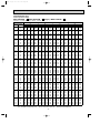
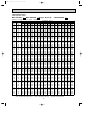
Q :Total capacity (kW)
SHC :Sensible heat capacity (kW)
SHF :Sensible heat factor
INPUT :Total power input (W)
35
DB :Dry-bulb temperature
WB :Wet-bulb temperature
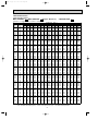
OB384--2.qxp 05.1.17 13:09 Page 36
PERFORMANCE DATA
COOL operation (230V)
MSC-CA20VB - E1
MSC-GA20VB - E1 (Single) : MUX-2A28VB - E1
CAPACITY : 2.4(kW) SHF : 0.74 INPUT : 760(W)
INDOOR INDOOR
DB(:) WB(:)
21
21
22
22
22
23
23
23
24
24
24
24
25
25
25
25
26
26
26
26
26
27
27
27
27
27
28
28
28
28
28
29
29
29
29
29
30
30
30
30
30
31
31
31
31
31
32
32
32
32
32
NOTE
18
20
18
20
22
18
20
22
18
20
22
24
18
20
22
24
18
20
22
24
26
18
20
22
24
26
18
20
22
24
26
18
20
22
24
26
18
20
22
24
26
18
20
22
24
26
18
20
22
24
26
Q
2.35
2.47
2.35
2.47
2.62
2.35
2.47
2.62
2.35
2.47
2.62
2.76
2.35
2.47
2.62
2.76
2.35
2.47
2.62
2.76
2.90
2.35
2.47
2.62
2.76
2.90
2.35
2.47
2.62
2.76
2.90
2.35
2.47
2.62
2.76
2.90
2.35
2.47
2.62
2.76
2.90
2.35
2.47
2.62
2.76
2.90
2.35
2.47
2.62
2.76
2.90
OUTDOOR DB(:)
35
40
SHC SHF INPUT Q SHC SHF INPUT
1.32 0.56 745 2.16 1.21 0.56 790
1.09 0.44 775 2.30 1.01 0.44 813
1.41 0.60 745 2.16 1.30 0.60 790
1.19 0.48 775 2.30 1.11 0.48 813
0.94 0.36 806 2.45 0.88 0.36 851
1.51 0.64 745 2.16 1.38 0.64 790
1.29 0.52 775 2.30 1.20 0.52 813
1.05 0.40 806 2.45 0.98 0.40 851
1.60 0.68 745 2.16 1.47 0.68 790
1.38 0.56 775 2.30 1.29 0.56 813
1.15 0.44 806 2.45 1.08 0.44 851
0.88 0.32 836 2.59 0.83 0.32 874
1.69 0.72 745 2.16 1.56 0.72 790
1.48 0.60 775 2.30 1.38 0.60 813
1.26 0.48 806 2.45 1.18 0.48 851
0.99 0.36 836 2.59 0.93 0.36 874
1.79 0.76 745 2.16 1.64 0.76 790
1.58 0.64 775 2.30 1.47 0.64 813
1.36 0.52 806 2.45 1.27 0.52 851
1.10 0.40 836 2.59 1.04 0.40 874
0.81 0.28 866 2.74 0.77 0.28 904
1.88 0.80 745 2.16 1.73 0.80 790
1.68 0.68 775 2.30 1.57 0.68 813
1.46 0.56 806 2.45 1.37 0.56 851
1.21 0.44 836 2.59 1.14 0.44 874
0.93 0.32 866 2.74 0.88 0.32 904
1.98 0.84 745 2.16 1.81 0.84 790
1.78 0.72 775 2.30 1.66 0.72 813
1.57 0.60 806 2.45 1.47 0.60 851
1.32 0.48 836 2.59 1.24 0.48 874
1.05 0.36 866 2.74 0.98 0.36 904
2.07 0.88 745 2.16 1.90 0.88 790
1.88 0.76 775 2.30 1.75 0.76 813
1.67 0.64 806 2.45 1.57 0.64 851
1.44 0.52 836 2.59 1.35 0.52 874
1.16 0.40 866 2.74 1.09 0.40 904
2.16 0.92 745 2.16 1.99 0.92 790
1.98 0.80 775 2.30 1.84 0.80 813
1.78 0.68 806 2.45 1.66 0.68 851
1.55 0.56 836 2.59 1.45 0.56 874
1.28 0.44 866 2.74 1.20 0.44 904
2.26 0.96 745 2.16 2.07 0.96 790
2.08 0.84 775 2.30 1.94 0.84 813
1.88 0.72 806 2.45 1.76 0.72 851
1.66 0.60 836 2.59 1.56 0.60 874
1.39 0.48 866 2.74 1.31 0.48 904
2.35 1.00 745 2.16 2.16 1.00 790
2.18 0.88 775 2.30 2.03 0.88 813
1.99 0.76 806 2.45 1.86 0.76 851
1.77 0.64 836 2.59 1.66 0.64 874
1.51 0.52 866 2.74 1.42 0.52 904
Q :Total capacity (kW)
SHC :Sensible heat capacity (kW)
Q
2.08
2.22
2.08
2.22
2.36
2.08
2.22
2.36
2.08
2.22
2.36
2.52
2.08
2.22
2.36
2.52
2.08
2.22
2.36
2.52
2.65
2.08
2.22
2.36
2.52
2.65
2.08
2.22
2.36
2.52
2.65
2.08
2.22
2.36
2.52
2.65
2.08
2.22
2.36
2.52
2.65
2.08
2.22
2.36
2.52
2.65
2.08
2.22
2.36
2.52
2.65
SHF :Sensible heat factor
INPUT :Total power input (W)
36
SHC
1.16
0.98
1.25
1.07
0.85
1.33
1.15
0.95
1.41
1.24
1.04
0.81
1.49
1.33
1.13
0.91
1.58
1.42
1.23
1.01
0.74
1.66
1.51
1.32
1.11
0.85
1.74
1.60
1.42
1.21
0.95
1.83
1.69
1.51
1.31
1.06
1.91
1.78
1.61
1.41
1.17
1.99
1.86
1.70
1.51
1.27
2.08
1.95
1.80
1.61
1.38
43
SHF INPUT
0.56 806
0.44 836
0.60 806
0.48 836
0.36 866
0.64 806
0.52 836
0.40 866
0.68 806
0.56 836
0.44 866
0.32 893
0.72 806
0.60 836
0.48 866
0.36 893
0.76 806
0.64 836
0.52 866
0.40 893
0.28 923
0.80 806
0.68 836
0.56 866
0.44 893
0.32 923
0.84 806
0.72 836
0.60 866
0.48 893
0.36 923
0.88 806
0.76 836
0.64 866
0.52 893
0.40 923
0.92 806
0.80 836
0.68 866
0.56 893
0.44 923
0.96 806
0.84 836
0.72 866
0.60 893
0.48 923
1.00 806
0.88 836
0.76 866
0.64 893
0.52 923
DB :Dry-bulb temperature
WB :Wet-bulb temperature
OB384--2.qxp 05.1.17 13:09 Page 37
PERFORMANCE DATA
COOL operation (230V)
MSC-CA20VB - E1
MSC-GA20VB - E1 (Single : Room B)
: MUX-2A59VB - E1
CAPACITY : 2.4(kW) SHF : 0.74 INPUT : 820(W)
INDOOR INDOOR
DB(:) WB(:)
21
21
22
22
22
23
23
23
24
24
24
24
25
25
25
25
26
26
26
26
26
27
27
27
27
27
28
28
28
28
28
29
29
29
29
29
30
30
30
30
30
31
31
31
31
31
32
32
32
32
32
NOTE
18
20
18
20
22
18
20
22
18
20
22
24
18
20
22
24
18
20
22
24
26
18
20
22
24
26
18
20
22
24
26
18
20
22
24
26
18
20
22
24
26
18
20
22
24
26
18
20
22
24
26
Q
2.82
2.94
2.82
2.94
3.06
2.82
2.94
3.06
2.82
2.94
3.06
3.22
2.82
2.94
3.06
3.22
2.82
2.94
3.06
3.22
3.31
2.82
2.94
3.06
3.22
3.31
2.82
2.94
3.06
3.22
3.31
2.82
2.94
3.06
3.22
3.31
2.82
2.94
3.06
3.22
3.31
2.82
2.94
3.06
3.22
3.31
2.82
2.94
3.06
3.22
3.31
OUTDOOR DB(:)
21
25
27
30
SHC SHF INPUT Q SHC SHF INPUT Q SHC SHF INPUT Q SHC SHF INPUT
1.58 0.56 656 2.70 1.51 0.56 689 2.59 1.45 0.56 722 2.50 1.40 0.56 754
1.29 0.44 689 2.82 1.24 0.44 730 2.74 1.20 0.44 746 2.64 1.16 0.44 779
1.69 0.60 656 2.70 1.62 0.60 689 2.59 1.56 0.60 722 2.50 1.50 0.60 754
1.41 0.48 689 2.82 1.35 0.48 730 2.74 1.31 0.48 746 2.64 1.27 0.48 779
1.10 0.36 713 2.95 1.06 0.36 759 2.88 1.04 0.36 779 2.76 0.99 0.36 812
1.80 0.64 656 2.70 1.73 0.64 689 2.59 1.66 0.64 722 2.50 1.60 0.64 754
1.53 0.52 689 2.82 1.47 0.52 730 2.74 1.42 0.52 746 2.64 1.37 0.52 779
1.22 0.40 713 2.95 1.18 0.40 759 2.88 1.15 0.40 779 2.76 1.10 0.40 812
1.92 0.68 656 2.70 1.84 0.68 689 2.59 1.76 0.68 722 2.50 1.70 0.68 754
1.65 0.56 689 2.82 1.58 0.56 730 2.74 1.53 0.56 746 2.64 1.48 0.56 779
1.35 0.44 713 2.95 1.30 0.44 759 2.88 1.27 0.44 779 2.76 1.21 0.44 812
1.03 0.32 746 3.10 0.99 0.32 787 3.02 0.97 0.32 812 2.93 0.94 0.32 853
2.03 0.72 656 2.70 1.94 0.72 689 2.59 1.87 0.72 722 2.50 1.80 0.72 754
1.76 0.60 689 2.82 1.69 0.60 730 2.74 1.64 0.60 746 2.64 1.58 0.60 779
1.47 0.48 713 2.95 1.42 0.48 759 2.88 1.38 0.48 779 2.76 1.32 0.48 812
1.16 0.36 746 3.10 1.11 0.36 787 3.02 1.09 0.36 812 2.93 1.05 0.36 853
2.14 0.76 656 2.70 2.05 0.76 689 2.59 1.97 0.76 722 2.50 1.90 0.76 754
1.88 0.64 689 2.82 1.80 0.64 730 2.74 1.75 0.64 746 2.64 1.69 0.64 779
1.59 0.52 713 2.95 1.54 0.52 759 2.88 1.50 0.52 779 2.76 1.44 0.52 812
1.29 0.40 746 3.10 1.24 0.40 787 3.02 1.21 0.40 812 2.93 1.17 0.40 853
0.93 0.28 787 3.22 0.90 0.28 828 3.17 0.89 0.28 853 3.07 0.86 0.28 877
2.26 0.80 656 2.70 2.16 0.80 689 2.59 2.07 0.80 722 2.50 2.00 0.80 754
2.00 0.68 689 2.82 1.92 0.68 730 2.74 1.86 0.68 746 2.64 1.80 0.68 779
1.71 0.56 713 2.95 1.65 0.56 759 2.88 1.61 0.56 779 2.76 1.55 0.56 812
1.42 0.44 746 3.10 1.36 0.44 787 3.02 1.33 0.44 812 2.93 1.29 0.44 853
1.06 0.32 787 3.22 1.03 0.32 828 3.17 1.01 0.32 853 3.07 0.98 0.32 877
2.37 0.84 656 2.70 2.27 0.84 689 2.59 2.18 0.84 722 2.50 2.10 0.84 754
2.12 0.72 689 2.82 2.03 0.72 730 2.74 1.97 0.72 746 2.64 1.90 0.72 779
1.84 0.60 713 2.95 1.77 0.60 759 2.88 1.73 0.60 779 2.76 1.66 0.60 812
1.54 0.48 746 3.10 1.49 0.48 787 3.02 1.45 0.48 812 2.93 1.41 0.48 853
1.19 0.36 787 3.22 1.16 0.36 828 3.17 1.14 0.36 853 3.07 1.11 0.36 877
2.48 0.88 656 2.70 2.38 0.88 689 2.59 2.28 0.88 722 2.50 2.20 0.88 754
2.23 0.76 689 2.82 2.14 0.76 730 2.74 2.08 0.76 746 2.64 2.01 0.76 779
1.96 0.64 713 2.95 1.89 0.64 759 2.88 1.84 0.64 779 2.76 1.77 0.64 812
1.67 0.52 746 3.10 1.61 0.52 787 3.02 1.57 0.52 812 2.93 1.52 0.52 853
1.32 0.40 787 3.22 1.29 0.40 828 3.17 1.27 0.40 853 3.07 1.23 0.40 877
2.59 0.92 656 2.70 2.48 0.92 689 2.59 2.38 0.92 722 2.50 2.30 0.92 754
2.35 0.80 689 2.82 2.26 0.80 730 2.74 2.19 0.80 746 2.64 2.11 0.80 779
2.08 0.68 713 2.95 2.01 0.68 759 2.88 1.96 0.68 779 2.76 1.88 0.68 812
1.80 0.56 746 3.10 1.73 0.56 787 3.02 1.69 0.56 812 2.93 1.64 0.56 853
1.46 0.44 787 3.22 1.42 0.44 828 3.17 1.39 0.44 853 3.07 1.35 0.44 877
2.71 0.96 656 2.70 2.59 0.96 689 2.59 2.49 0.96 722 2.50 2.40 0.96 754
2.47 0.84 689 2.82 2.37 0.84 730 2.74 2.30 0.84 746 2.64 2.22 0.84 779
2.20 0.72 713 2.95 2.13 0.72 759 2.88 2.07 0.72 779 2.76 1.99 0.72 812
1.93 0.60 746 3.10 1.86 0.60 787 3.02 1.81 0.60 812 2.93 1.76 0.60 853
1.59 0.48 787 3.22 1.54 0.48 828 3.17 1.52 0.48 853 3.07 1.47 0.48 877
2.82 1.00 656 2.70 2.70 1.00 689 2.59 2.59 1.00 722 2.50 2.50 1.00 754
2.59 0.88 689 2.82 2.48 0.88 730 2.74 2.41 0.88 746 2.64 2.32 0.88 779
2.33 0.76 713 2.95 2.24 0.76 759 2.88 2.19 0.76 779 2.76 2.10 0.76 812
2.06 0.64 746 3.10 1.98 0.64 787 3.02 1.94 0.64 812 2.93 1.87 0.64 853
1.72 0.52 787 3.22 1.67 0.52 828 3.17 1.65 0.52 853 3.07 1.60 0.52 877
Q :Total capacity (kW)
SHC :Sensible heat capacity (kW)
SHF :Sensible heat factor
INPUT :Total power input (W)
37
DB :Dry-bulb temperature
WB :Wet-bulb temperature
OB384--2.qxp 05.1.17 13:09 Page 38
PERFORMANCE DATA
COOL operation (230V)
MSC-CA20VB - E1
MSC-GA20VB - E1 (Single : Room B)
: MUX-2A59VB - E1
CAPACITY : 2.4(kW) SHF : 0.74 INPUT : 820(W)
INDOOR INDOOR
DB(:) WB(:)
21
21
22
22
22
23
23
23
24
24
24
24
25
25
25
25
26
26
26
26
26
27
27
27
27
27
28
28
28
28
28
29
29
29
29
29
30
30
30
30
30
31
31
31
31
31
32
32
32
32
32
NOTE
18
20
18
20
22
18
20
22
18
20
22
24
18
20
22
24
18
20
22
24
26
18
20
22
24
26
18
20
22
24
26
18
20
22
24
26
18
20
22
24
26
18
20
22
24
26
18
20
22
24
26
Q
2.35
2.47
2.35
2.47
2.62
2.35
2.47
2.62
2.35
2.47
2.62
2.76
2.35
2.47
2.62
2.76
2.35
2.47
2.62
2.76
2.90
2.35
2.47
2.62
2.76
2.90
2.35
2.47
2.62
2.76
2.90
2.35
2.47
2.62
2.76
2.90
2.35
2.47
2.62
2.76
2.90
2.35
2.47
2.62
2.76
2.90
2.35
2.47
2.62
2.76
2.90
OUTDOOR DB(:)
35
40
SHC SHF INPUT Q SHC SHF INPUT
1.32 0.56 804 2.16 1.21 0.56 853
1.09 0.44 836 2.30 1.01 0.44 877
1.41 0.60 804 2.16 1.30 0.60 853
1.19 0.48 836 2.30 1.11 0.48 877
0.94 0.36 869 2.45 0.88 0.36 918
1.51 0.64 804 2.16 1.38 0.64 853
1.29 0.52 836 2.30 1.20 0.52 877
1.05 0.40 869 2.45 0.98 0.40 918
1.60 0.68 804 2.16 1.47 0.68 853
1.38 0.56 836 2.30 1.29 0.56 877
1.15 0.44 869 2.45 1.08 0.44 918
0.88 0.32 902 2.59 0.83 0.32 943
1.69 0.72 804 2.16 1.56 0.72 853
1.48 0.60 836 2.30 1.38 0.60 877
1.26 0.48 869 2.45 1.18 0.48 918
0.99 0.36 902 2.59 0.93 0.36 943
1.79 0.76 804 2.16 1.64 0.76 853
1.58 0.64 836 2.30 1.47 0.64 877
1.36 0.52 869 2.45 1.27 0.52 918
1.10 0.40 902 2.59 1.04 0.40 943
0.81 0.28 935 2.74 0.77 0.28 976
1.88 0.80 804 2.16 1.73 0.80 853
1.68 0.68 836 2.30 1.57 0.68 877
1.46 0.56 869 2.45 1.37 0.56 918
1.21 0.44 902 2.59 1.14 0.44 943
0.93 0.32 935 2.74 0.88 0.32 976
1.98 0.84 804 2.16 1.81 0.84 853
1.78 0.72 836 2.30 1.66 0.72 877
1.57 0.60 869 2.45 1.47 0.60 918
1.32 0.48 902 2.59 1.24 0.48 943
1.05 0.36 935 2.74 0.98 0.36 976
2.07 0.88 804 2.16 1.90 0.88 853
1.88 0.76 836 2.30 1.75 0.76 877
1.67 0.64 869 2.45 1.57 0.64 918
1.44 0.52 902 2.59 1.35 0.52 943
1.16 0.40 935 2.74 1.09 0.40 976
2.16 0.92 804 2.16 1.99 0.92 853
1.98 0.80 836 2.30 1.84 0.80 877
1.78 0.68 869 2.45 1.66 0.68 918
1.55 0.56 902 2.59 1.45 0.56 943
1.28 0.44 935 2.74 1.20 0.44 976
2.26 0.96 804 2.16 2.07 0.96 853
2.08 0.84 836 2.30 1.94 0.84 877
1.88 0.72 869 2.45 1.76 0.72 918
1.66 0.60 902 2.59 1.56 0.60 943
1.39 0.48 935 2.74 1.31 0.48 976
2.35 1.00 804 2.16 2.16 1.00 853
2.18 0.88 836 2.30 2.03 0.88 877
1.99 0.76 869 2.45 1.86 0.76 918
1.77 0.64 902 2.59 1.66 0.64 943
1.51 0.52 935 2.74 1.42 0.52 976
Q :Total capacity (kW)
SHC :Sensible heat capacity (kW)
Q
2.08
2.22
2.08
2.22
2.36
2.08
2.22
2.36
2.08
2.22
2.36
2.52
2.08
2.22
2.36
2.52
2.08
2.22
2.36
2.52
2.65
2.08
2.22
2.36
2.52
2.65
2.08
2.22
2.36
2.52
2.65
2.08
2.22
2.36
2.52
2.65
2.08
2.22
2.36
2.52
2.65
2.08
2.22
2.36
2.52
2.65
2.08
2.22
2.36
2.52
2.65
SHF :Sensible heat factor
INPUT :Total power input (W)
38
SHC
1.16
0.98
1.25
1.07
0.85
1.33
1.15
0.95
1.41
1.24
1.04
0.81
1.49
1.33
1.13
0.91
1.58
1.42
1.23
1.01
0.74
1.66
1.51
1.32
1.11
0.85
1.74
1.60
1.42
1.21
0.95
1.83
1.69
1.51
1.31
1.06
1.91
1.78
1.61
1.41
1.17
1.99
1.86
1.70
1.51
1.27
2.08
1.95
1.80
1.61
1.38
43
SHF INPUT
0.56 869
0.44 902
0.60 869
0.48 902
0.36 935
0.64 869
0.52 902
0.40 935
0.68 869
0.56 902
0.44 935
0.32 964
0.72 869
0.60 902
0.48 935
0.36 964
0.76 869
0.64 902
0.52 935
0.40 964
0.28 996
0.80 869
0.68 902
0.56 935
0.44 964
0.32 996
0.84 869
0.72 902
0.60 935
0.48 964
0.36 996
0.88 869
0.76 902
0.64 935
0.52 964
0.40 996
0.92 869
0.80 902
0.68 935
0.56 964
0.44 996
0.96 869
0.84 902
0.72 935
0.60 964
0.48 996
1.00 869
0.88 902
0.76 935
0.64 964
0.52 996
DB :Dry-bulb temperature
WB :Wet-bulb temperature
OB384--2.qxp 05.1.17 13:09 Page 39
PERFORMANCE DATA
COOL operation (230V)
MSC-CA35VB - E1
MSC-GA35VB - E1 (Single : Room A)
: MUX-2A59VB - E1
CAPACITY : 3.5(kW) SHF : 0.73 INPUT : 1320(W)
INDOOR INDOOR
DB(:) WB(:)
21
21
22
22
22
23
23
23
24
24
24
24
25
25
25
25
26
26
26
26
26
27
27
27
27
27
28
28
28
28
28
29
29
29
29
29
30
30
30
30
30
31
31
31
31
31
32
32
32
32
32
NOTE
18
20
18
20
22
18
20
22
18
20
22
24
18
20
22
24
18
20
22
24
26
18
20
22
24
26
18
20
22
24
26
18
20
22
24
26
18
20
22
24
26
18
20
22
24
26
18
20
22
24
26
Q
4.11
4.29
4.11
4.29
4.46
4.11
4.29
4.46
4.11
4.29
4.46
4.69
4.11
4.29
4.46
4.69
4.11
4.29
4.46
4.69
4.83
4.11
4.29
4.46
4.69
4.83
4.11
4.29
4.46
4.69
4.83
4.11
4.29
4.46
4.69
4.83
4.11
4.29
4.46
4.69
4.83
4.11
4.29
4.46
4.69
4.83
4.11
4.29
4.46
4.69
4.83
OUTDOOR DB(:)
21
25
27
30
SHC SHF INPUT Q SHC SHF INPUT Q SHC SHF INPUT Q SHC SHF INPUT
2.25 0.55 1056 3.94 2.15 0.55 1109 3.78 2.07 0.55 1162 3.64 1.99 0.55 1214
1.83 0.43 1109 4.11 1.76 0.43 1175 3.99 1.70 0.43 1201 3.85 1.64 0.43 1254
2.41 0.59 1056 3.94 2.31 0.59 1109 3.78 2.22 0.59 1162 3.64 2.14 0.59 1214
2.00 0.47 1109 4.11 1.92 0.47 1175 3.99 1.86 0.47 1201 3.85 1.80 0.47 1254
1.55 0.35 1148 4.31 1.49 0.35 1221 4.20 1.46 0.35 1254 4.03 1.40 0.35 1307
2.58 0.63 1056 3.94 2.47 0.63 1109 3.78 2.37 0.63 1162 3.64 2.28 0.63 1214
2.17 0.51 1109 4.11 2.09 0.51 1175 3.99 2.02 0.51 1201 3.85 1.95 0.51 1254
1.73 0.39 1148 4.31 1.67 0.39 1221 4.20 1.63 0.39 1254 4.03 1.56 0.39 1307
2.74 0.67 1056 3.94 2.63 0.67 1109 3.78 2.52 0.67 1162 3.64 2.43 0.67 1214
2.35 0.55 1109 4.11 2.25 0.55 1175 3.99 2.18 0.55 1201 3.85 2.11 0.55 1254
1.91 0.43 1148 4.31 1.84 0.43 1221 4.20 1.79 0.43 1254 4.03 1.72 0.43 1307
1.44 0.31 1201 4.52 1.39 0.31 1267 4.41 1.35 0.31 1307 4.27 1.31 0.31 1373
2.91 0.71 1056 3.94 2.78 0.71 1109 3.78 2.67 0.71 1162 3.64 2.57 0.71 1214
2.52 0.59 1109 4.11 2.41 0.59 1175 3.99 2.34 0.59 1201 3.85 2.26 0.59 1254
2.08 0.47 1148 4.31 2.01 0.47 1221 4.20 1.96 0.47 1254 4.03 1.88 0.47 1307
1.63 0.35 1201 4.52 1.57 0.35 1267 4.41 1.53 0.35 1307 4.27 1.48 0.35 1373
3.07 0.75 1056 3.94 2.94 0.75 1109 3.78 2.82 0.75 1162 3.64 2.72 0.75 1214
2.69 0.63 1109 4.11 2.58 0.63 1175 3.99 2.50 0.63 1201 3.85 2.41 0.63 1254
2.26 0.51 1148 4.31 2.18 0.51 1221 4.20 2.13 0.51 1254 4.03 2.04 0.51 1307
1.82 0.39 1201 4.52 1.75 0.39 1267 4.41 1.71 0.39 1307 4.27 1.65 0.39 1373
1.29 0.27 1267 4.69 1.25 0.27 1333 4.62 1.23 0.27 1373 4.48 1.20 0.27 1412
3.24 0.79 1056 3.94 3.10 0.79 1109 3.78 2.97 0.79 1162 3.64 2.86 0.79 1214
2.86 0.67 1109 4.11 2.74 0.67 1175 3.99 2.66 0.67 1201 3.85 2.57 0.67 1254
2.44 0.55 1148 4.31 2.35 0.55 1221 4.20 2.30 0.55 1254 4.03 2.20 0.55 1307
2.00 0.43 1201 4.52 1.93 0.43 1267 4.41 1.88 0.43 1307 4.27 1.82 0.43 1373
1.48 0.31 1267 4.69 1.44 0.31 1333 4.62 1.42 0.31 1373 4.48 1.38 0.31 1412
3.40 0.83 1056 3.94 3.26 0.83 1109 3.78 3.13 0.83 1162 3.64 3.01 0.83 1214
3.03 0.71 1109 4.11 2.91 0.71 1175 3.99 2.82 0.71 1201 3.85 2.72 0.71 1254
2.62 0.59 1148 4.31 2.53 0.59 1221 4.20 2.47 0.59 1254 4.03 2.36 0.59 1307
2.19 0.47 1201 4.52 2.11 0.47 1267 4.41 2.06 0.47 1307 4.27 1.99 0.47 1373
1.68 0.35 1267 4.69 1.63 0.35 1333 4.62 1.60 0.35 1373 4.48 1.55 0.35 1412
3.57 0.87 1056 3.94 3.41 0.87 1109 3.78 3.28 0.87 1162 3.64 3.16 0.87 1214
3.20 0.75 1109 4.11 3.07 0.75 1175 3.99 2.98 0.75 1201 3.85 2.88 0.75 1254
2.80 0.63 1148 4.31 2.70 0.63 1221 4.20 2.63 0.63 1254 4.03 2.52 0.63 1307
2.38 0.51 1201 4.52 2.29 0.51 1267 4.41 2.24 0.51 1307 4.27 2.16 0.51 1373
1.87 0.39 1267 4.69 1.82 0.39 1333 4.62 1.79 0.39 1373 4.48 1.73 0.39 1412
3.73 0.91 1056 3.94 3.57 0.91 1109 3.78 3.43 0.91 1162 3.64 3.30 0.91 1214
3.37 0.79 1109 4.11 3.24 0.79 1175 3.99 3.14 0.79 1201 3.85 3.03 0.79 1254
2.98 0.67 1148 4.31 2.87 0.67 1221 4.20 2.80 0.67 1254 4.03 2.68 0.67 1307
2.57 0.55 1201 4.52 2.47 0.55 1267 4.41 2.41 0.55 1307 4.27 2.34 0.55 1373
2.06 0.43 1267 4.69 2.00 0.43 1333 4.62 1.97 0.43 1373 4.48 1.91 0.43 1412
3.89 0.95 1056 3.94 3.73 0.95 1109 3.78 3.58 0.95 1162 3.64 3.45 0.95 1214
3.55 0.83 1109 4.11 3.40 0.83 1175 3.99 3.30 0.83 1201 3.85 3.18 0.83 1254
3.15 0.71 1148 4.31 3.04 0.71 1221 4.20 2.97 0.71 1254 4.03 2.85 0.71 1307
2.75 0.59 1201 4.52 2.65 0.59 1267 4.41 2.59 0.59 1307 4.27 2.51 0.59 1373
2.26 0.47 1267 4.69 2.19 0.47 1333 4.62 2.16 0.47 1373 4.48 2.09 0.47 1412
4.06 0.99 1056 3.94 3.89 0.99 1109 3.78 3.73 0.99 1162 3.64 3.59 0.99 1214
3.72 0.87 1109 4.11 3.57 0.87 1175 3.99 3.46 0.87 1201 3.85 3.34 0.87 1254
3.33 0.75 1148 4.31 3.22 0.75 1221 4.20 3.14 0.75 1254 4.03 3.01 0.75 1307
2.94 0.63 1201 4.52 2.83 0.63 1267 4.41 2.77 0.63 1307 4.27 2.68 0.63 1373
2.45 0.51 1267 4.69 2.38 0.51 1333 4.62 2.34 0.51 1373 4.48 2.27 0.51 1412
Q :Total capacity (kW)
SHC :Sensible heat capacity (kW)
SHF :Sensible heat factor
INPUT :Total power input (W)
39
DB :Dry-bulb temperature
WB :Wet-bulb temperature
OB384--2.qxp 05.1.17 13:09 Page 40
PERFORMANCE DATA
COOL operation (230V)
MSC-CA35VB - E1
MSC-GA35VB - E1 (Single : Room A)
: MUX-2A59VB - E1
CAPACITY : 3.5(kW) SHF : 0.73 INPUT : 1320(W)
INDOOR INDOOR
DB(:) WB(:)
21
21
22
22
22
23
23
23
24
24
24
24
25
25
25
25
26
26
26
26
26
27
27
27
27
27
28
28
28
28
28
29
29
29
29
29
30
30
30
30
30
31
31
31
31
31
32
32
32
32
32
NOTE
18
20
18
20
22
18
20
22
18
20
22
24
18
20
22
24
18
20
22
24
26
18
20
22
24
26
18
20
22
24
26
18
20
22
24
26
18
20
22
24
26
18
20
22
24
26
18
20
22
24
26
Q
3.43
3.61
3.43
3.61
3.82
3.43
3.61
3.82
3.43
3.61
3.82
4.03
3.43
3.61
3.82
4.03
3.43
3.61
3.82
4.03
4.24
3.43
3.61
3.82
4.03
4.24
3.43
3.61
3.82
4.03
4.24
3.43
3.61
3.82
4.03
4.24
3.43
3.61
3.82
4.03
4.24
3.43
3.61
3.82
4.03
4.24
3.43
3.61
3.82
4.03
4.24
OUTDOOR DB(:)
35
40
SHC SHF INPUT Q SHC SHF INPUT
1.88 0.55 1294 3.15 1.72 0.55 1373
1.54 0.43 1346 3.36 1.43 0.43 1412
2.01 0.59 1294 3.15 1.85 0.59 1373
1.68 0.47 1346 3.36 1.57 0.47 1412
1.32 0.35 1399 3.57 1.24 0.35 1478
2.15 0.63 1294 3.15 1.98 0.63 1373
1.83 0.51 1346 3.36 1.70 0.51 1412
1.48 0.39 1399 3.57 1.38 0.39 1478
2.29 0.67 1294 3.15 2.10 0.67 1373
1.97 0.55 1346 3.36 1.84 0.55 1412
1.63 0.43 1399 3.57 1.52 0.43 1478
1.24 0.31 1452 3.78 1.16 0.31 1518
2.43 0.71 1294 3.15 2.23 0.71 1373
2.12 0.59 1346 3.36 1.97 0.59 1412
1.78 0.47 1399 3.57 1.67 0.47 1478
1.40 0.35 1452 3.78 1.31 0.35 1518
2.56 0.75 1294 3.15 2.35 0.75 1373
2.26 0.63 1346 3.36 2.11 0.63 1412
1.93 0.51 1399 3.57 1.81 0.51 1478
1.56 0.39 1452 3.78 1.46 0.39 1518
1.13 0.27 1505 3.99 1.07 0.27 1571
2.70 0.79 1294 3.15 2.48 0.79 1373
2.40 0.67 1346 3.36 2.24 0.67 1412
2.09 0.55 1399 3.57 1.95 0.55 1478
1.72 0.43 1452 3.78 1.61 0.43 1518
1.30 0.31 1505 3.99 1.22 0.31 1571
2.84 0.83 1294 3.15 2.61 0.83 1373
2.55 0.71 1346 3.36 2.38 0.71 1412
2.24 0.59 1399 3.57 2.10 0.59 1478
1.88 0.47 1452 3.78 1.77 0.47 1518
1.47 0.35 1505 3.99 1.38 0.35 1571
2.97 0.87 1294 3.15 2.73 0.87 1373
2.69 0.75 1346 3.36 2.51 0.75 1412
2.39 0.63 1399 3.57 2.24 0.63 1478
2.04 0.51 1452 3.78 1.92 0.51 1518
1.64 0.39 1505 3.99 1.54 0.39 1571
3.11 0.91 1294 3.15 2.86 0.91 1373
2.84 0.79 1346 3.36 2.64 0.79 1412
2.54 0.67 1399 3.57 2.38 0.67 1478
2.20 0.55 1452 3.78 2.07 0.55 1518
1.81 0.43 1505 3.99 1.70 0.43 1571
3.25 0.95 1294 3.15 2.98 0.95 1373
2.98 0.83 1346 3.36 2.78 0.83 1412
2.70 0.71 1399 3.57 2.52 0.71 1478
2.36 0.59 1452 3.78 2.22 0.59 1518
1.98 0.47 1505 3.99 1.86 0.47 1571
3.39 0.99 1294 3.15 3.11 0.99 1373
3.13 0.87 1346 3.36 2.91 0.87 1412
2.85 0.75 1399 3.57 2.67 0.75 1478
2.52 0.63 1452 3.78 2.37 0.63 1518
2.15 0.51 1505 3.99 2.02 0.51 1571
Q :Total capacity (kW)
SHC :Sensible heat capacity (kW)
Q
3.03
3.24
3.03
3.24
3.45
3.03
3.24
3.45
3.03
3.24
3.45
3.68
3.03
3.24
3.45
3.68
3.03
3.24
3.45
3.68
3.87
3.03
3.24
3.45
3.68
3.87
3.03
3.24
3.45
3.68
3.87
3.03
3.24
3.45
3.68
3.87
3.03
3.24
3.45
3.68
3.87
3.03
3.24
3.45
3.68
3.87
3.03
3.24
3.45
3.68
3.87
SHF :Sensible heat factor
INPUT :Total power input (W)
40
SHC
1.66
1.38
1.78
1.51
1.20
1.90
1.64
1.33
2.02
1.77
1.47
1.13
2.14
1.90
1.61
1.28
2.26
2.03
1.75
1.42
1.03
2.38
2.16
1.89
1.57
1.19
2.50
2.29
2.02
1.72
1.34
2.62
2.42
2.16
1.86
1.50
2.75
2.55
2.30
2.01
1.65
2.87
2.68
2.44
2.16
1.81
2.99
2.81
2.58
2.30
1.96
43
SHF INPUT
0.55 1399
0.43 1452
0.59 1399
0.47 1452
0.35 1505
0.63 1399
0.51 1452
0.39 1505
0.67 1399
0.55 1452
0.43 1505
0.31 1551
0.71 1399
0.59 1452
0.47 1505
0.35 1551
0.75 1399
0.63 1452
0.51 1505
0.39 1551
0.27 1604
0.79 1399
0.67 1452
0.55 1505
0.43 1551
0.31 1604
0.83 1399
0.71 1452
0.59 1505
0.47 1551
0.35 1604
0.87 1399
0.75 1452
0.63 1505
0.51 1551
0.39 1604
0.91 1399
0.79 1452
0.67 1505
0.55 1551
0.43 1604
0.95 1399
0.83 1452
0.71 1505
0.59 1551
0.47 1604
0.99 1399
0.87 1452
0.75 1505
0.63 1551
0.51 1604
DB :Dry-bulb temperature
WB :Wet-bulb temperature
OB384--2.qxp 05.1.17 13:09 Page 41
PERFORMANCE DATA
COOL operation (230V)
MSC-CA25VB - E1
MSC-GA25VB - E1 (Single : Room A)
: MUX-3A60VB - E1
CAPACITY : 2.6(kW) SHF : 0.75 INPUT : 850(W)
OUTDOOR DB(:)
21
25
27
Q SHC SHF INPUT Q SHC SHF INPUT Q SHC SHF INPUT Q
18
3.06 1.74 0.57 680 2.93 1.67 0.57 714 2.81 1.60 0.57 748 2.70
20
3.19 1.43 0.45 714 3.06 1.37 0.45 757 2.96 1.33 0.45 774 2.86
18
3.06 1.86 0.61 680 2.93 1.78 0.61 714 2.81 1.71 0.61 748 2.70
20
3.19 1.56 0.49 714 3.06 1.50 0.49 757 2.96 1.45 0.49 774 2.86
22
3.32 1.23 0.37 740 3.20 1.18 0.37 786 3.12 1.15 0.37 808 2.99
18
3.06 1.99 0.65 680 2.93 1.90 0.65 714 2.81 1.83 0.65 748 2.70
20
3.19 1.69 0.53 714 3.06 1.62 0.53 757 2.96 1.57 0.53 774 2.86
22
3.32 1.36 0.41 740 3.20 1.31 0.41 786 3.12 1.28 0.41 808 2.99
18
3.06 2.11 0.69 680 2.93 2.02 0.69 714 2.81 1.94 0.69 748 2.70
20
3.19 1.82 0.57 714 3.06 1.74 0.57 757 2.96 1.69 0.57 774 2.86
22
3.32 1.49 0.45 740 3.20 1.44 0.45 786 3.12 1.40 0.45 808 2.99
24
3.48 1.15 0.33 774 3.35 1.11 0.33 816 3.28 1.08 0.33 842 3.17
18
3.06 2.23 0.73 680 2.93 2.14 0.73 714 2.81 2.05 0.73 748 2.70
20
3.19 1.94 0.61 714 3.06 1.86 0.61 757 2.96 1.81 0.61 774 2.86
22
3.32 1.62 0.49 740 3.20 1.57 0.49 786 3.12 1.53 0.49 808 2.99
24
3.48 1.29 0.37 774 3.35 1.24 0.37 816 3.28 1.21 0.37 842 3.17
18
3.06 2.35 0.77 680 2.93 2.25 0.77 714 2.81 2.16 0.77 748 2.70
20
3.19 2.07 0.65 714 3.06 1.99 0.65 757 2.96 1.93 0.65 774 2.86
22
3.32 1.76 0.53 740 3.20 1.69 0.53 786 3.12 1.65 0.53 808 2.99
24
3.48 1.43 0.41 774 3.35 1.38 0.41 816 3.28 1.34 0.41 842 3.17
26
3.59 1.04 0.29 816 3.48 1.01 0.29 859 3.43 1.00 0.29 884 3.33
18
3.06 2.47 0.81 680 2.93 2.37 0.81 714 2.81 2.27 0.81 748 2.70
20
3.19 2.20 0.69 714 3.06 2.11 0.69 757 2.96 2.05 0.69 774 2.86
22
3.32 1.89 0.57 740 3.20 1.82 0.57 786 3.12 1.78 0.57 808 2.99
24
3.48 1.57 0.45 774 3.35 1.51 0.45 816 3.28 1.47 0.45 842 3.17
26
3.59 1.18 0.33 816 3.48 1.15 0.33 859 3.43 1.13 0.33 884 3.33
18
3.06 2.60 0.85 680 2.93 2.49 0.85 714 2.81 2.39 0.85 748 2.70
20
3.19 2.33 0.73 714 3.06 2.23 0.73 757 2.96 2.16 0.73 774 2.86
22
3.32 2.02 0.61 740 3.20 1.95 0.61 786 3.12 1.90 0.61 808 2.99
24
3.48 1.71 0.49 774 3.35 1.64 0.49 816 3.28 1.61 0.49 842 3.17
26
3.59 1.33 0.37 816 3.48 1.29 0.37 859 3.43 1.27 0.37 884 3.33
18
3.06 2.72 0.89 680 2.93 2.60 0.89 714 2.81 2.50 0.89 748 2.70
20
3.19 2.45 0.77 714 3.06 2.35 0.77 757 2.96 2.28 0.77 774 2.86
22
3.32 2.15 0.65 740 3.20 2.08 0.65 786 3.12 2.03 0.65 808 2.99
24
3.48 1.85 0.53 774 3.35 1.78 0.53 816 3.28 1.74 0.53 842 3.17
26
3.59 1.47 0.41 816 3.48 1.43 0.41 859 3.43 1.41 0.41 884 3.33
18
3.06 2.84 0.93 680 2.93 2.72 0.93 714 2.81 2.61 0.93 748 2.70
20
3.19 2.58 0.81 714 3.06 2.47 0.81 757 2.96 2.40 0.81 774 2.86
22
3.32 2.29 0.69 740 3.20 2.21 0.69 786 3.12 2.15 0.69 808 2.99
24
3.48 1.99 0.57 774 3.35 1.91 0.57 816 3.28 1.87 0.57 842 3.17
26
3.59 1.61 0.45 816 3.48 1.57 0.45 859 3.43 1.54 0.45 884 3.33
18
3.06 2.96 0.97 680 2.93 2.84 0.97 714 2.81 2.72 0.97 748 2.70
20
3.19 2.71 0.85 714 3.06 2.60 0.85 757 2.96 2.52 0.85 774 2.86
22
3.32 2.42 0.73 740 3.20 2.33 0.73 786 3.12 2.28 0.73 808 2.99
24
3.48 2.13 0.61 774 3.35 2.05 0.61 816 3.28 2.00 0.61 842 3.17
26
3.59 1.76 0.49 816 3.48 1.71 0.49 859 3.43 1.68 0.49 884 3.33
18
3.06 3.09 1.01 680 2.93 2.95 1.01 714 2.81 2.84 1.01 748 2.70
20
3.19 2.83 0.89 714 3.06 2.72 0.89 757 2.96 2.64 0.89 774 2.86
22
3.32 2.55 0.77 740 3.20 2.46 0.77 786 3.12 2.40 0.77 808 2.99
24
3.48 2.26 0.65 774 3.35 2.18 0.65 816 3.28 2.13 0.65 842 3.17
26
3.59 1.90 0.53 816 3.48 1.85 0.53 859 3.43 1.82 0.53 884 3.33
Q :Total capacity (kW)
SHF :Sensible heat factor
DB :Dry-bulb temperature
SHC :Sensible heat capacity (kW)
INPUT :Total power input (W)
WB :Wet-bulb temperature
41
INDOOR INDOOR
DB(:) WB(:)
21
21
22
22
22
23
23
23
24
24
24
24
25
25
25
25
26
26
26
26
26
27
27
27
27
27
28
28
28
28
28
29
29
29
29
29
30
30
30
30
30
31
31
31
31
31
32
32
32
32
32
NOTE
SHC
1.54
1.29
1.65
1.40
1.11
1.76
1.52
1.23
1.87
1.63
1.35
1.05
1.97
1.74
1.47
1.17
2.08
1.86
1.58
1.30
0.97
2.19
1.97
1.70
1.43
1.10
2.30
2.09
1.82
1.55
1.23
2.41
2.20
1.94
1.68
1.36
2.51
2.32
2.06
1.81
1.50
2.62
2.43
2.18
1.93
1.63
2.73
2.55
2.30
2.06
1.76
30
SHF INPUT
0.57 782
0.45 808
0.61 782
0.49 808
0.37 842
0.65 782
0.53 808
0.41 842
0.69 782
0.57 808
0.45 842
0.33 884
0.73 782
0.61 808
0.49 842
0.37 884
0.77 782
0.65 808
0.53 842
0.41 884
0.29 910
0.81 782
0.69 808
0.57 842
0.45 884
0.33 910
0.85 782
0.73 808
0.61 842
0.49 884
0.37 910
0.89 782
0.77 808
0.65 842
0.53 884
0.41 910
0.93 782
0.81 808
0.69 842
0.57 884
0.45 910
0.97 782
0.85 808
0.73 842
0.61 884
0.49 910
1.01 782
0.89 808
0.77 842
0.65 884
0.53 910
OB384--2.qxp 05.1.17 13:09 Page 42
PERFORMANCE DATA
COOL operation (230V)
MSC-CA25VB - E1
MSC-GA25VB - E1 (Single : Room A)
: MUX-3A60VB - E1
CAPACITY : 2.6(kW) SHF : 0.75 INPUT : 850(W)
35
Q SHC SHF INPUT
18
2.55 1.45 0.57 833
20
2.68 1.21 0.45 867
18
2.55 1.55 0.61 833
20
2.68 1.31 0.49 867
22
2.83 1.05 0.37 901
18
2.55 1.66 0.65 833
20
2.68 1.42 0.53 867
22
2.83 1.16 0.41 901
18
2.55 1.76 0.69 833
20
2.68 1.53 0.57 867
22
2.83 1.28 0.45 901
24
2.99 0.99 0.33 935
18
2.55 1.86 0.73 833
20
2.68 1.63 0.61 867
22
2.83 1.39 0.49 901
24
2.99 1.11 0.37 935
18
2.55 1.96 0.77 833
20
2.68 1.74 0.65 867
22
2.83 1.50 0.53 901
24
2.99 1.23 0.41 935
26
3.15 0.91 0.29 969
18
2.55 2.06 0.81 833
20
2.68 1.85 0.69 867
22
2.83 1.62 0.57 901
24
2.99 1.35 0.45 935
26
3.15 1.04 0.33 969
18
2.55 2.17 0.85 833
20
2.68 1.95 0.73 867
22
2.83 1.73 0.61 901
24
2.99 1.47 0.49 935
26
3.15 1.16 0.37 969
18
2.55 2.27 0.89 833
20
2.68 2.06 0.77 867
22
2.83 1.84 0.65 901
24
2.99 1.58 0.53 935
26
3.15 1.29 0.41 969
18
2.55 2.37 0.93 833
20
2.68 2.17 0.81 867
22
2.83 1.96 0.69 901
24
2.99 1.70 0.57 935
26
3.15 1.42 0.45 969
18
2.55 2.47 0.97 833
20
2.68 2.28 0.85 867
22
2.83 2.07 0.73 901
24
2.99 1.82 0.61 935
26
3.15 1.54 0.49 969
18
2.55 2.57 1.01 833
20
2.68 2.38 0.89 867
22
2.83 2.18 0.77 901
24
2.99 1.94 0.65 935
26
3.15 1.67 0.53 969
Q :Total capacity (kW)
SHC :Sensible heat capacity (kW)
INDOOR INDOOR
DB(:) WB(:)
21
21
22
22
22
23
23
23
24
24
24
24
25
25
25
25
26
26
26
26
26
27
27
27
27
27
28
28
28
28
28
29
29
29
29
29
30
30
30
30
30
31
31
31
31
31
32
32
32
32
32
NOTE
OUTDOOR DB(:)
40
Q SHC SHF INPUT Q
2.34 1.33 0.57 884 2.25
2.50 1.12 0.45 910 2.41
2.34 1.43 0.61 884 2.25
2.50 1.22 0.49 910 2.41
2.65 0.98 0.37 952 2.56
2.34 1.52 0.65 884 2.25
2.50 1.32 0.53 910 2.41
2.65 1.09 0.41 952 2.56
2.34 1.61 0.69 884 2.25
2.50 1.42 0.57 910 2.41
2.65 1.19 0.45 952 2.56
2.81 0.93 0.33 978 2.73
2.34 1.71 0.73 884 2.25
2.50 1.52 0.61 910 2.41
2.65 1.30 0.49 952 2.56
2.81 1.04 0.37 978 2.73
2.34 1.80 0.77 884 2.25
2.50 1.62 0.65 910 2.41
2.65 1.41 0.53 952 2.56
2.81 1.15 0.41 978 2.73
2.96 0.86 0.29 1012 2.87
2.34 1.90 0.81 884 2.25
2.50 1.72 0.69 910 2.41
2.65 1.51 0.57 952 2.56
2.81 1.26 0.45 978 2.73
2.96 0.98 0.33 1012 2.87
2.34 1.99 0.85 884 2.25
2.50 1.82 0.73 910 2.41
2.65 1.62 0.61 952 2.56
2.81 1.38 0.49 978 2.73
2.96 1.10 0.37 1012 2.87
2.34 2.08 0.89 884 2.25
2.50 1.92 0.77 910 2.41
2.65 1.72 0.65 952 2.56
2.81 1.49 0.53 978 2.73
2.96 1.22 0.41 1012 2.87
2.34 2.18 0.93 884 2.25
2.50 2.02 0.81 910 2.41
2.65 1.83 0.69 952 2.56
2.81 1.60 0.57 978 2.73
2.96 1.33 0.45 1012 2.87
2.34 2.27 0.97 884 2.25
2.50 2.12 0.85 910 2.41
2.65 1.94 0.73 952 2.56
2.81 1.71 0.61 978 2.73
2.96 1.45 0.49 1012 2.87
2.34 2.36 1.01 884 2.25
2.50 2.22 0.89 910 2.41
2.65 2.04 0.77 952 2.56
2.81 1.83 0.65 978 2.73
2.96 1.57 0.53 1012 2.87
SHF :Sensible heat factor
INPUT :Total power input (W)
42
43
SHC SHF INPUT
1.28 0.57 901
1.08 0.45 935
1.37 0.61 901
1.18 0.49 935
0.95 0.37 969
1.46 0.65 901
1.27 0.53 935
1.05 0.41 969
1.55 0.69 901
1.37 0.57 935
1.15 0.45 969
0.90 0.33 999
1.64 0.73 901
1.47 0.61 935
1.25 0.49 969
1.01 0.37 999
1.73 0.77 901
1.56 0.65 935
1.36 0.53 969
1.12 0.41 999
0.83 0.29 1033
1.82 0.81 901
1.66 0.69 935
1.46 0.57 969
1.23 0.45 999
0.95 0.33 1033
1.91 0.85 901
1.76 0.73 935
1.56 0.61 969
1.34 0.49 999
1.06 0.37 1033
2.00 0.89 901
1.85 0.77 935
1.66 0.65 969
1.45 0.53 999
1.18 0.41 1033
2.09 0.93 901
1.95 0.81 935
1.77 0.69 969
1.56 0.57 999
1.29 0.45 1033
2.18 0.97 901
2.04 0.85 935
1.87 0.73 969
1.67 0.61 999
1.41 0.49 1033
2.27 1.01 901
2.14 0.89 935
1.97 0.77 969
1.77 0.65 999
1.52 0.53 1033
DB :Dry-bulb temperature
WB :Wet-bulb temperature
OB384--2.qxp 05.1.17 13:09 Page 43
PERFORMANCE DATA
COOL operation (230V)
MSC-CA25VB - E1
MSC-GA25VB - E1 (Single : Room B)
: MUX-3A60VB - E1
CAPACITY : 2.9(kW) SHF : 0.71 INPUT : 1110(W)
INDOOR INDOOR
DB(:) WB(:)
21
21
22
22
22
23
23
23
24
24
24
24
25
25
25
25
26
26
26
26
26
27
27
27
27
27
28
28
28
28
28
29
29
29
29
29
30
30
30
30
30
31
31
31
31
31
32
32
32
32
32
NOTE
18
20
18
20
22
18
20
22
18
20
22
24
18
20
22
24
18
20
22
24
26
18
20
22
24
26
18
20
22
24
26
18
20
22
24
26
18
20
22
24
26
18
20
22
24
26
18
20
22
24
26
Q
3.41
3.55
3.41
3.55
3.70
3.41
3.55
3.70
3.41
3.55
3.70
3.89
3.41
3.55
3.70
3.89
3.41
3.55
3.70
3.89
4.00
3.41
3.55
3.70
3.89
4.00
3.41
3.55
3.70
3.89
4.00
3.41
3.55
3.70
3.89
4.00
3.41
3.55
3.70
3.89
4.00
3.41
3.55
3.70
3.89
4.00
3.41
3.55
3.70
3.89
4.00
OUTDOOR DB(:)
21
25
27
30
SHC SHF INPUT Q SHC SHF INPUT Q SHC SHF INPUT Q SHC SHF INPUT
1.82 0.53 888 3.26 1.74 0.53 932 3.13 1.67 0.53 977 3.02 1.61 0.53 1021
1.47 0.41 932 3.41 1.41 0.41 988 3.31 1.37 0.41 1010 3.19 1.32 0.41 1055
1.95 0.57 888 3.26 1.87 0.57 932 3.13 1.79 0.57 977 3.02 1.73 0.57 1021
1.61 0.45 932 3.41 1.54 0.45 988 3.31 1.50 0.45 1010 3.19 1.45 0.45 1055
1.23 0.33 966 3.57 1.19 0.33 1027 3.48 1.16 0.33 1055 3.34 1.11 0.33 1099
2.09 0.61 888 3.26 2.00 0.61 932 3.13 1.92 0.61 977 3.02 1.85 0.61 1021
1.75 0.49 932 3.41 1.68 0.49 988 3.31 1.63 0.49 1010 3.19 1.57 0.49 1055
1.38 0.37 966 3.57 1.33 0.37 1027 3.48 1.30 0.37 1055 3.34 1.24 0.37 1099
2.23 0.65 888 3.26 2.13 0.65 932 3.13 2.05 0.65 977 3.02 1.97 0.65 1021
1.89 0.53 932 3.41 1.82 0.53 988 3.31 1.76 0.53 1010 3.19 1.70 0.53 1055
1.53 0.41 966 3.57 1.47 0.41 1027 3.48 1.44 0.41 1055 3.34 1.38 0.41 1099
1.14 0.29 1010 3.74 1.10 0.29 1066 3.65 1.07 0.29 1099 3.54 1.04 0.29 1154
2.36 0.69 888 3.26 2.26 0.69 932 3.13 2.17 0.69 977 3.02 2.09 0.69 1021
2.04 0.57 932 3.41 1.95 0.57 988 3.31 1.89 0.57 1010 3.19 1.83 0.57 1055
1.67 0.45 966 3.57 1.62 0.45 1027 3.48 1.58 0.45 1055 3.34 1.51 0.45 1099
1.29 0.33 1010 3.74 1.25 0.33 1066 3.65 1.22 0.33 1099 3.54 1.18 0.33 1154
2.50 0.73 888 3.26 2.39 0.73 932 3.13 2.30 0.73 977 3.02 2.21 0.73 1021
2.18 0.61 932 3.41 2.09 0.61 988 3.31 2.03 0.61 1010 3.19 1.96 0.61 1055
1.82 0.49 966 3.57 1.76 0.49 1027 3.48 1.72 0.49 1055 3.34 1.64 0.49 1099
1.45 0.37 1010 3.74 1.40 0.37 1066 3.65 1.36 0.37 1099 3.54 1.32 0.37 1154
1.01 0.25 1066 3.89 0.98 0.25 1121 3.83 0.97 0.25 1154 3.71 0.94 0.25 1188
2.63 0.77 888 3.26 2.52 0.77 932 3.13 2.42 0.77 977 3.02 2.33 0.77 1021
2.32 0.65 932 3.41 2.23 0.65 988 3.31 2.16 0.65 1010 3.19 2.08 0.65 1055
1.97 0.53 966 3.57 1.90 0.53 1027 3.48 1.85 0.53 1055 3.34 1.78 0.53 1099
1.60 0.41 1010 3.74 1.55 0.41 1066 3.65 1.51 0.41 1099 3.54 1.46 0.41 1154
1.17 0.29 1066 3.89 1.14 0.29 1121 3.83 1.12 0.29 1154 3.71 1.09 0.29 1188
2.77 0.81 888 3.26 2.65 0.81 932 3.13 2.55 0.81 977 3.02 2.45 0.81 1021
2.46 0.69 932 3.41 2.36 0.69 988 3.31 2.29 0.69 1010 3.19 2.21 0.69 1055
2.12 0.57 966 3.57 2.04 0.57 1027 3.48 1.99 0.57 1055 3.34 1.91 0.57 1099
1.76 0.45 1010 3.74 1.69 0.45 1066 3.65 1.66 0.45 1099 3.54 1.60 0.45 1154
1.33 0.33 1066 3.89 1.29 0.33 1121 3.83 1.27 0.33 1154 3.71 1.24 0.33 1188
2.91 0.85 888 3.26 2.78 0.85 932 3.13 2.67 0.85 977 3.02 2.57 0.85 1021
2.60 0.73 932 3.41 2.50 0.73 988 3.31 2.42 0.73 1010 3.19 2.34 0.73 1055
2.27 0.61 966 3.57 2.19 0.61 1027 3.48 2.13 0.61 1055 3.34 2.04 0.61 1099
1.92 0.49 1010 3.74 1.84 0.49 1066 3.65 1.80 0.49 1099 3.54 1.74 0.49 1154
1.49 0.37 1066 3.89 1.45 0.37 1121 3.83 1.43 0.37 1154 3.71 1.38 0.37 1188
3.04 0.89 888 3.26 2.91 0.89 932 3.13 2.80 0.89 977 3.02 2.69 0.89 1021
2.75 0.77 932 3.41 2.63 0.77 988 3.31 2.56 0.77 1010 3.19 2.47 0.77 1055
2.41 0.65 966 3.57 2.33 0.65 1027 3.48 2.27 0.65 1055 3.34 2.18 0.65 1099
2.07 0.53 1010 3.74 1.99 0.53 1066 3.65 1.95 0.53 1099 3.54 1.89 0.53 1154
1.65 0.41 1066 3.89 1.60 0.41 1121 3.83 1.58 0.41 1154 3.71 1.53 0.41 1188
3.18 0.93 888 3.26 3.04 0.93 932 3.13 2.92 0.93 977 3.02 2.81 0.93 1021
2.89 0.81 932 3.41 2.77 0.81 988 3.31 2.69 0.81 1010 3.19 2.59 0.81 1055
2.56 0.69 966 3.57 2.47 0.69 1027 3.48 2.41 0.69 1055 3.34 2.31 0.69 1099
2.23 0.57 1010 3.74 2.14 0.57 1066 3.65 2.09 0.57 1099 3.54 2.03 0.57 1154
1.81 0.45 1066 3.89 1.76 0.45 1121 3.83 1.73 0.45 1154 3.71 1.68 0.45 1188
3.32 0.97 888 3.26 3.17 0.97 932 3.13 3.05 0.97 977 3.02 2.93 0.97 1021
3.03 0.85 932 3.41 2.91 0.85 988 3.31 2.82 0.85 1010 3.19 2.72 0.85 1055
2.71 0.73 966 3.57 2.61 0.73 1027 3.48 2.55 0.73 1055 3.34 2.44 0.73 1099
2.38 0.61 1010 3.74 2.29 0.61 1066 3.65 2.24 0.61 1099 3.54 2.17 0.61 1154
1.97 0.49 1066 3.89 1.92 0.49 1121 3.83 1.89 0.49 1154 3.71 1.83 0.49 1188
Q :Total capacity (kW)
SHC :Sensible heat capacity (kW)
SHF :Sensible heat factor
INPUT :Total power input (W)
43
DB :Dry-bulb temperature
WB :Wet-bulb temperature
OB384--2.qxp 05.1.17 13:09 Page 44
PERFORMANCE DATA
COOL operation (230V)
MSC-CA25VB - E1
MSC-GA25VB - E1 (Single : Room B)
: MUX-3A60VB - E1
CAPACITY : 2.9(kW) SHF : 0.71 INPUT : 1110(W)
INDOOR INDOOR
DB(:) WB(:)
21
21
22
22
22
23
23
23
24
24
24
24
25
25
25
25
26
26
26
26
26
27
27
27
27
27
28
28
28
28
28
29
29
29
29
29
30
30
30
30
30
31
31
31
31
31
32
32
32
32
32
NOTE
18
20
18
20
22
18
20
22
18
20
22
24
18
20
22
24
18
20
22
24
26
18
20
22
24
26
18
20
22
24
26
18
20
22
24
26
18
20
22
24
26
18
20
22
24
26
18
20
22
24
26
Q
2.84
2.99
2.84
2.99
3.16
2.84
2.99
3.16
2.84
2.99
3.16
3.34
2.84
2.99
3.16
3.34
2.84
2.99
3.16
3.34
3.51
2.84
2.99
3.16
3.34
3.51
2.84
2.99
3.16
3.34
3.51
2.84
2.99
3.16
3.34
3.51
2.84
2.99
3.16
3.34
3.51
2.84
2.99
3.16
3.34
3.51
2.84
2.99
3.16
3.34
3.51
OUTDOOR DB(:)
35
40
SHC SHF INPUT Q SHC SHF INPUT
1.51 0.53 1088 2.61 1.39 0.53 1154
1.23 0.41 1132 2.78 1.15 0.41 1188
1.63 0.57 1088 2.61 1.50 0.57 1154
1.35 0.45 1132 2.78 1.26 0.45 1188
1.05 0.33 1177 2.96 0.99 0.33 1243
1.74 0.61 1088 2.61 1.60 0.61 1154
1.47 0.49 1132 2.78 1.37 0.49 1188
1.18 0.37 1177 2.96 1.10 0.37 1243
1.86 0.65 1088 2.61 1.70 0.65 1154
1.59 0.53 1132 2.78 1.48 0.53 1188
1.31 0.41 1177 2.96 1.22 0.41 1243
0.98 0.29 1221 3.13 0.92 0.29 1277
1.97 0.69 1088 2.61 1.81 0.69 1154
1.71 0.57 1132 2.78 1.60 0.57 1188
1.43 0.45 1177 2.96 1.34 0.45 1243
1.11 0.33 1221 3.13 1.04 0.33 1277
2.08 0.73 1088 2.61 1.91 0.73 1154
1.83 0.61 1132 2.78 1.71 0.61 1188
1.56 0.49 1177 2.96 1.46 0.49 1243
1.24 0.37 1221 3.13 1.17 0.37 1277
0.89 0.25 1265 3.31 0.84 0.25 1321
2.20 0.77 1088 2.61 2.02 0.77 1154
1.95 0.65 1132 2.78 1.82 0.65 1188
1.68 0.53 1177 2.96 1.58 0.53 1243
1.38 0.41 1221 3.13 1.29 0.41 1277
1.03 0.29 1265 3.31 0.97 0.29 1321
2.31 0.81 1088 2.61 2.12 0.81 1154
2.07 0.69 1132 2.78 1.93 0.69 1188
1.81 0.57 1177 2.96 1.69 0.57 1243
1.51 0.45 1221 3.13 1.42 0.45 1277
1.17 0.33 1265 3.31 1.10 0.33 1321
2.42 0.85 1088 2.61 2.23 0.85 1154
2.19 0.73 1132 2.78 2.04 0.73 1188
1.94 0.61 1177 2.96 1.81 0.61 1243
1.64 0.49 1221 3.13 1.54 0.49 1277
1.31 0.37 1265 3.31 1.23 0.37 1321
2.54 0.89 1088 2.61 2.33 0.89 1154
2.31 0.77 1132 2.78 2.15 0.77 1188
2.06 0.65 1177 2.96 1.93 0.65 1243
1.78 0.53 1221 3.13 1.67 0.53 1277
1.45 0.41 1265 3.31 1.37 0.41 1321
2.65 0.93 1088 2.61 2.44 0.93 1154
2.43 0.81 1132 2.78 2.26 0.81 1188
2.19 0.69 1177 2.96 2.05 0.69 1243
1.91 0.57 1221 3.13 1.79 0.57 1277
1.59 0.45 1265 3.31 1.50 0.45 1321
2.77 0.97 1088 2.61 2.54 0.97 1154
2.55 0.85 1132 2.78 2.37 0.85 1188
2.32 0.73 1177 2.96 2.17 0.73 1243
2.04 0.61 1221 3.13 1.92 0.61 1277
1.73 0.49 1265 3.31 1.63 0.49 1321
Q :Total capacity (kW)
SHC :Sensible heat capacity (kW)
Q
2.51
2.68
2.51
2.68
2.86
2.51
2.68
2.86
2.51
2.68
2.86
3.05
2.51
2.68
2.86
3.05
2.51
2.68
2.86
3.05
3.20
2.51
2.68
2.86
3.05
3.20
2.51
2.68
2.86
3.05
3.20
2.51
2.68
2.86
3.05
3.20
2.51
2.68
2.86
3.05
3.20
2.51
2.68
2.86
3.05
3.20
2.51
2.68
2.86
3.05
3.20
SHF :Sensible heat factor
INPUT :Total power input (W)
44
SHC
1.34
1.11
1.44
1.22
0.95
1.54
1.32
1.07
1.64
1.43
1.18
0.89
1.74
1.54
1.29
1.01
1.84
1.64
1.41
1.14
0.81
1.94
1.75
1.52
1.26
0.94
2.04
1.86
1.64
1.38
1.07
2.14
1.97
1.75
1.50
1.20
2.24
2.07
1.87
1.62
1.32
2.34
2.18
1.98
1.74
1.45
2.44
2.29
2.09
1.87
1.58
43
SHF INPUT
0.53 1177
0.41 1221
0.57 1177
0.45 1221
0.33 1265
0.61 1177
0.49 1221
0.37 1265
0.65 1177
0.53 1221
0.41 1265
0.29 1304
0.69 1177
0.57 1221
0.45 1265
0.33 1304
0.73 1177
0.61 1221
0.49 1265
0.37 1304
0.25 1349
0.77 1177
0.65 1221
0.53 1265
0.41 1304
0.29 1349
0.81 1177
0.69 1221
0.57 1265
0.45 1304
0.33 1349
0.85 1177
0.73 1221
0.61 1265
0.49 1304
0.37 1349
0.89 1177
0.77 1221
0.65 1265
0.53 1304
0.41 1349
0.93 1177
0.81 1221
0.69 1265
0.57 1304
0.45 1349
0.97 1177
0.85 1221
0.73 1265
0.61 1304
0.49 1349
DB :Dry-bulb temperature
WB :Wet-bulb temperature
OB384--2.qxp 05.1.17 13:09 Page 45
PERFORMANCE DATA
COOL operation (230V)
MSC-CA35VB - E1 MSC-GA35VB - E1 (Single : Room A)
: MUX-3A63VB - E1
CAPACITY : 3.5(kW) SHF : 0.73 INPUT : 1320(W)
INDOOR INDOOR
DB(:) WB(:)
21
21
22
22
22
23
23
23
24
24
24
24
25
25
25
25
26
26
26
26
26
27
27
27
27
27
28
28
28
28
28
29
29
29
29
29
30
30
30
30
30
31
31
31
31
31
32
32
32
32
32
NOTE
Q
21
SHC SHF INPUT
18
4.11 2.25 0.55
20
4.29 1.83 0.43
18
4.11 2.41 0.59
20
4.29 2.00 0.47
22
4.46 1.55 0.35
18
4.11 2.58 0.63
20
4.29 2.17 0.51
22
4.46 1.73 0.39
18
4.11 2.74 0.67
20
4.29 2.35 0.55
22
4.46 1.91 0.43
24
4.69 1.44 0.31
18
4.11 2.91 0.71
20
4.29 2.52 0.59
22
4.46 2.08 0.47
24
4.69 1.63 0.35
18
4.11 3.07 0.75
20
4.29 2.69 0.63
22
4.46 2.26 0.51
24
4.69 1.82 0.39
26
4.83 1.29 0.27
18
4.11 3.24 0.79
20
4.29 2.86 0.67
22
4.46 2.44 0.55
24
4.69 2.00 0.43
26
4.83 1.48 0.31
18
4.11 3.40 0.83
20
4.29 3.03 0.71
22
4.46 2.62 0.59
24
4.69 2.19 0.47
26
4.83 1.68 0.35
18
4.11 3.57 0.87
20
4.29 3.20 0.75
22
4.46 2.80 0.63
24
4.69 2.38 0.51
26
4.83 1.87 0.39
18
4.11 3.73 0.91
20
4.29 3.37 0.79
22
4.46 2.98 0.67
24
4.69 2.57 0.55
26
4.83 2.06 0.43
18
4.11 3.89 0.95
20
4.29 3.55 0.83
22
4.46 3.15 0.71
24
4.69 2.75 0.59
26
4.83 2.26 0.47
18
4.11 4.06 0.99
20
4.29 3.72 0.87
22
4.46 3.33 0.75
24
4.69 2.94 0.63
26
4.83 2.45 0.51
Q :Total capacity (kW)
SHC :Sensible heat capacity
1056
1109
1056
1109
1148
1056
1109
1148
1056
1109
1148
1201
1056
1109
1148
1201
1056
1109
1148
1201
1267
1056
1109
1148
1201
1267
1056
1109
1148
1201
1267
1056
1109
1148
1201
1267
1056
1109
1148
1201
1267
1056
1109
1148
1201
1267
1056
1109
1148
1201
1267
(kW)
OUTDOOR DB(:)
25
27
SHC SHF INPUT Q SHC SHF INPUT
Q
3.94 2.15 0.55 1109 3.78
4.11 1.76 0.43 1175 3.99
3.94 2.31 0.59 1109 3.78
4.11 1.92 0.47 1175 3.99
4.31 1.49 0.35 1221 4.20
3.94 2.47 0.63 1109 3.78
4.11 2.09 0.51 1175 3.99
4.31 1.67 0.39 1221 4.20
3.94 2.63 0.67 1109 3.78
4.11 2.25 0.55 1175 3.99
4.31 1.84 0.43 1221 4.20
4.52 1.39 0.31 1267 4.41
3.94 2.78 0.71 1109 3.78
4.11 2.41 0.59 1175 3.99
4.31 2.01 0.47 1221 4.20
4.52 1.57 0.35 1267 4.41
3.94 2.94 0.75 1109 3.78
4.11 2.58 0.63 1175 3.99
4.31 2.18 0.51 1221 4.20
4.52 1.75 0.39 1267 4.41
4.69 1.25 0.27 1333 4.62
3.94 3.10 0.79 1109 3.78
4.11 2.74 0.67 1175 3.99
4.31 2.35 0.55 1221 4.20
4.52 1.93 0.43 1267 4.41
4.69 1.44 0.31 1333 4.62
3.94 3.26 0.83 1109 3.78
4.11 2.91 0.71 1175 3.99
4.31 2.53 0.59 1221 4.20
4.52 2.11 0.47 1267 4.41
4.69 1.63 0.35 1333 4.62
3.94 3.41 0.87 1109 3.78
4.11 3.07 0.75 1175 3.99
4.31 2.70 0.63 1221 4.20
4.52 2.29 0.51 1267 4.41
4.69 1.82 0.39 1333 4.62
3.94 3.57 0.91 1109 3.78
4.11 3.24 0.79 1175 3.99
4.31 2.87 0.67 1221 4.20
4.52 2.47 0.55 1267 4.41
4.69 2.00 0.43 1333 4.62
3.94 3.73 0.95 1109 3.78
4.11 3.40 0.83 1175 3.99
4.31 3.04 0.71 1221 4.20
4.52 2.65 0.59 1267 4.41
4.69 2.19 0.47 1333 4.62
3.94 3.89 0.99 1109 3.78
4.11 3.57 0.87 1175 3.99
4.31 3.22 0.75 1221 4.20
4.52 2.83 0.63 1267 4.41
4.69 2.38 0.51 1333 4.62
SHF :Sensible heat factor
INPUT :Total power input (W)
45
Q
30
SHC SHF INPUT
2.07 0.55 1162 3.64 1.99
1.70 0.43 1201 3.85 1.64
2.22 0.59 1162 3.64 2.14
1.86 0.47 1201 3.85 1.80
1.46 0.35 1254 4.03 1.40
2.37 0.63 1162 3.64 2.28
2.02 0.51 1201 3.85 1.95
1.63 0.39 1254 4.03 1.56
2.52 0.67 1162 3.64 2.43
2.18 0.55 1201 3.85 2.11
1.79 0.43 1254 4.03 1.72
1.35 0.31 1307 4.27 1.31
2.67 0.71 1162 3.64 2.57
2.34 0.59 1201 3.85 2.26
1.96 0.47 1254 4.03 1.88
1.53 0.35 1307 4.27 1.48
2.82 0.75 1162 3.64 2.72
2.50 0.63 1201 3.85 2.41
2.13 0.51 1254 4.03 2.04
1.71 0.39 1307 4.27 1.65
1.23 0.27 1373 4.48 1.20
2.97 0.79 1162 3.64 2.86
2.66 0.67 1201 3.85 2.57
2.30 0.55 1254 4.03 2.20
1.88 0.43 1307 4.27 1.82
1.42 0.31 1373 4.48 1.38
3.13 0.83 1162 3.64 3.01
2.82 0.71 1201 3.85 2.72
2.47 0.59 1254 4.03 2.36
2.06 0.47 1307 4.27 1.99
1.60 0.35 1373 4.48 1.55
3.28 0.87 1162 3.64 3.16
2.98 0.75 1201 3.85 2.88
2.63 0.63 1254 4.03 2.52
2.24 0.51 1307 4.27 2.16
1.79 0.39 1373 4.48 1.73
3.43 0.91 1162 3.64 3.30
3.14 0.79 1201 3.85 3.03
2.80 0.67 1254 4.03 2.68
2.41 0.55 1307 4.27 2.34
1.97 0.43 1373 4.48 1.91
3.58 0.95 1162 3.64 3.45
3.30 0.83 1201 3.85 3.18
2.97 0.71 1254 4.03 2.85
2.59 0.59 1307 4.27 2.51
2.16 0.47 1373 4.48 2.09
3.73 0.99 1162 3.64 3.59
3.46 0.87 1201 3.85 3.34
3.14 0.75 1254 4.03 3.01
2.77 0.63 1307 4.27 2.68
2.34 0.51 1373 4.48 2.27
DB :Dry-bulb temperature
WB :Wet-bulb temperature
0.55
0.43
0.59
0.47
0.35
0.63
0.51
0.39
0.67
0.55
0.43
0.31
0.71
0.59
0.47
0.35
0.75
0.63
0.51
0.39
0.27
0.79
0.67
0.55
0.43
0.31
0.83
0.71
0.59
0.47
0.35
0.87
0.75
0.63
0.51
0.39
0.91
0.79
0.67
0.55
0.43
0.95
0.83
0.71
0.59
0.47
0.99
0.87
0.75
0.63
0.51
1214
1254
1214
1254
1307
1214
1254
1307
1214
1254
1307
1373
1214
1254
1307
1373
1214
1254
1307
1373
1412
1214
1254
1307
1373
1412
1214
1254
1307
1373
1412
1214
1254
1307
1373
1412
1214
1254
1307
1373
1412
1214
1254
1307
1373
1412
1214
1254
1307
1373
1412
OB384--2.qxp 05.1.17 13:09 Page 46
PERFORMANCE DATA
COOL operation (230V)
MSC-CA35VB - E1 MSC-GA35VB - E1 (Single : Room A)
CAPACITY : 3.5(kW) SHF : 0.73 INPUT : 1320(W)
OUTDOOR DB(:)
35
40
INDOOR INDOOR
DB(:) WB(:) Q SHC SHF INPUT Q SHC SHF INPUT
21
21
22
22
22
23
23
23
24
24
24
24
25
25
25
25
26
26
26
26
26
27
27
27
27
27
28
28
28
28
28
29
29
29
29
29
30
30
30
30
30
31
31
31
31
31
32
32
32
32
32
NOTE
18
3.43 1.88 0.55
20
3.61 1.54 0.43
18
3.43 2.01 0.59
20
3.61 1.68 0.47
22
3.82 1.32 0.35
18
3.43 2.15 0.63
20
3.61 1.83 0.51
22
3.82 1.48 0.39
18
3.43 2.29 0.67
20
3.61 1.97 0.55
22
3.82 1.63 0.43
24
4.03 1.24 0.31
18
3.43 2.43 0.71
20
3.61 2.12 0.59
22
3.82 1.78 0.47
24
4.03 1.40 0.35
18
3.43 2.56 0.75
20
3.61 2.26 0.63
22
3.82 1.93 0.51
24
4.03 1.56 0.39
26
4.24 1.13 0.27
18
3.43 2.70 0.79
20
3.61 2.40 0.67
22
3.82 2.09 0.55
24
4.03 1.72 0.43
26
4.24 1.30 0.31
18
3.43 2.84 0.83
20
3.61 2.55 0.71
22
3.82 2.24 0.59
24
4.03 1.88 0.47
26
4.24 1.47 0.35
18
3.43 2.97 0.87
20
3.61 2.69 0.75
22
3.82 2.39 0.63
24
4.03 2.04 0.51
26
4.24 1.64 0.39
18
3.43 3.11 0.91
20
3.61 2.84 0.79
22
3.82 2.54 0.67
24
4.03 2.20 0.55
26
4.24 1.81 0.43
18
3.43 3.25 0.95
20
3.61 2.98 0.83
22
3.82 2.70 0.71
24
4.03 2.36 0.59
26
4.24 1.98 0.47
18
3.43 3.39 0.99
20
3.61 3.13 0.87
22
3.82 2.85 0.75
24
4.03 2.52 0.63
26
4.24 2.15 0.51
Q :Total capacity (kW)
SHC :Sensible heat capacity
1294
1346
1294
1346
1399
1294
1346
1399
1294
1346
1399
1452
1294
1346
1399
1452
1294
1346
1399
1452
1505
1294
1346
1399
1452
1505
1294
1346
1399
1452
1505
1294
1346
1399
1452
1505
1294
1346
1399
1452
1505
1294
1346
1399
1452
1505
1294
1346
1399
1452
1505
(kW)
Q
3.15 1.72 0.55 1373 3.03
3.36 1.43 0.43 1412 3.24
3.15 1.85 0.59 1373 3.03
3.36 1.57 0.47 1412 3.24
3.57 1.24 0.35 1478 3.45
3.15 1.98 0.63 1373 3.03
3.36 1.70 0.51 1412 3.24
3.57 1.38 0.39 1478 3.45
3.15 2.10 0.67 1373 3.03
3.36 1.84 0.55 1412 3.24
3.57 1.52 0.43 1478 3.45
3.78 1.16 0.31 1518 3.68
3.15 2.23 0.71 1373 3.03
3.36 1.97 0.59 1412 3.24
3.57 1.67 0.47 1478 3.45
3.78 1.31 0.35 1518 3.68
3.15 2.35 0.75 1373 3.03
3.36 2.11 0.63 1412 3.24
3.57 1.81 0.51 1478 3.45
3.78 1.46 0.39 1518 3.68
3.99 1.07 0.27 1571 3.87
3.15 2.48 0.79 1373 3.03
3.36 2.24 0.67 1412 3.24
3.57 1.95 0.55 1478 3.45
3.78 1.61 0.43 1518 3.68
3.99 1.22 0.31 1571 3.87
3.15 2.61 0.83 1373 3.03
3.36 2.38 0.71 1412 3.24
3.57 2.10 0.59 1478 3.45
3.78 1.77 0.47 1518 3.68
3.99 1.38 0.35 1571 3.87
3.15 2.73 0.87 1373 3.03
3.36 2.51 0.75 1412 3.24
3.57 2.24 0.63 1478 3.45
3.78 1.92 0.51 1518 3.68
3.99 1.54 0.39 1571 3.87
3.15 2.86 0.91 1373 3.03
3.36 2.64 0.79 1412 3.24
3.57 2.38 0.67 1478 3.45
3.78 2.07 0.55 1518 3.68
3.99 1.70 0.43 1571 3.87
3.15 2.98 0.95 1373 3.03
3.36 2.78 0.83 1412 3.24
3.57 2.52 0.71 1478 3.45
3.78 2.22 0.59 1518 3.68
3.99 1.86 0.47 1571 3.87
3.15 3.11 0.99 1373 3.03
3.36 2.91 0.87 1412 3.24
3.57 2.67 0.75 1478 3.45
3.78 2.37 0.63 1518 3.68
3.99 2.02 0.51 1571 3.87
SHF :Sensible heat factor
INPUT :Total power input (W)
46
: MUX-3A63VB - E1
43
SHC SHF INPUT
1.66 0.55 1399
1.38 0.43 1452
1.78 0.59 1399
1.51 0.47 1452
1.20 0.35 1505
1.90 0.63 1399
1.64 0.51 1452
1.33 0.39 1505
2.02 0.67 1399
1.77 0.55 1452
1.47 0.43 1505
1.13 0.31 1551
2.14 0.71 1399
1.90 0.59 1452
1.61 0.47 1505
1.28 0.35 1551
2.26 0.75 1399
2.03 0.63 1452
1.75 0.51 1505
1.42 0.39 1551
1.03 0.27 1604
2.38 0.79 1399
2.16 0.67 1452
1.89 0.55 1505
1.57 0.43 1551
1.19 0.31 1604
2.50 0.83 1399
2.29 0.71 1452
2.02 0.59 1505
1.72 0.47 1551
1.34 0.35 1604
2.62 0.87 1399
2.42 0.75 1452
2.16 0.63 1505
1.86 0.51 1551
1.50 0.39 1604
2.75 0.91 1399
2.55 0.79 1452
2.30 0.67 1505
2.01 0.55 1551
1.65 0.43 1604
2.87 0.95 1399
2.68 0.83 1452
2.44 0.71 1505
2.16 0.59 1551
1.81 0.47 1604
2.99 0.99 1399
2.81 0.87 1452
2.58 0.75 1505
2.30 0.63 1551
1.96 0.51 1604
DB :Dry-bulb temperature
WB :Wet-bulb temperature
OB384--2.qxp 05.1.17 13:09 Page 47
PERFORMANCE DATA
COOL operation (230V)
MSC-CA20VB - E1 MSC-GA20VB - E1 (Single : Room B or C)
: MUX-3A63VB - E1
CAPACITY : 2.4(kW) SHF : 0.74 INPUT : 850(W)
INDOOR INDOOR
DB(:) WB(:)
21
21
22
22
22
23
23
23
24
24
24
24
25
25
25
25
26
26
26
26
26
27
27
27
27
27
28
28
28
28
28
29
29
29
29
29
30
30
30
30
30
31
31
31
31
31
32
32
32
32
32
NOTE
Q
21
SHC SHF INPUT
18
2.82 1.58 0.56
20
2.94 1.29 0.44
18
2.82 1.69 0.60
20
2.94 1.41 0.48
22
3.06 1.10 0.36
18
2.82 1.80 0.64
20
2.94 1.53 0.52
22
3.06 1.22 0.40
18
2.82 1.92 0.68
20
2.94 1.65 0.56
22
3.06 1.35 0.44
24
3.22 1.03 0.32
18
2.82 2.03 0.72
20
2.94 1.76 0.60
22
3.06 1.47 0.48
24
3.22 1.16 0.36
18
2.82 2.14 0.76
20
2.94 1.88 0.64
22
3.06 1.59 0.52
24
3.22 1.29 0.40
26
3.31 0.93 0.28
18
2.82 2.26 0.80
20
2.94 2.00 0.68
22
3.06 1.71 0.56
24
3.22 1.42 0.44
26
3.31 1.06 0.32
18
2.82 2.37 0.84
20
2.94 2.12 0.72
22
3.06 1.84 0.60
24
3.22 1.54 0.48
26
3.31 1.19 0.36
18
2.82 2.48 0.88
20
2.94 2.23 0.76
22
3.06 1.96 0.64
24
3.22 1.67 0.52
26
3.31 1.32 0.40
18
2.82 2.59 0.92
20
2.94 2.35 0.80
22
3.06 2.08 0.68
24
3.22 1.80 0.56
26
3.31 1.46 0.44
18
2.82 2.71 0.96
20
2.94 2.47 0.84
22
3.06 2.20 0.72
24
3.22 1.93 0.60
26
3.31 1.59 0.48
18
2.82 2.82 1.00
20
2.94 2.59 0.88
22
3.06 2.33 0.76
24
3.22 2.06 0.64
26
3.31 1.72 0.52
Q :Total capacity (kW)
SHC :Sensible heat capacity
680
714
680
714
740
680
714
740
680
714
740
774
680
714
740
774
680
714
740
774
816
680
714
740
774
816
680
714
740
774
816
680
714
740
774
816
680
714
740
774
816
680
714
740
774
816
680
714
740
774
816
(kW)
Q
OUTDOOR DB(:)
25
27
SHC SHF INPUT Q SHC SHF INPUT
2.70 1.51 0.56 714 2.59
2.82 1.24 0.44 757 2.74
2.70 1.62 0.60 714 2.59
2.82 1.35 0.48 757 2.74
2.95 1.06 0.36 786 2.88
2.70 1.73 0.64 714 2.59
2.82 1.47 0.52 757 2.74
2.95 1.18 0.40 786 2.88
2.70 1.84 0.68 714 2.59
2.82 1.58 0.56 757 2.74
2.95 1.30 0.44 786 2.88
3.10 0.99 0.32 816 3.02
2.70 1.94 0.72 714 2.59
2.82 1.69 0.60 757 2.74
2.95 1.42 0.48 786 2.88
3.10 1.11 0.36 816 3.02
2.70 2.05 0.76 714 2.59
2.82 1.80 0.64 757 2.74
2.95 1.54 0.52 786 2.88
3.10 1.24 0.40 816 3.02
3.22 0.90 0.28 859 3.17
2.70 2.16 0.80 714 2.59
2.82 1.92 0.68 757 2.74
2.95 1.65 0.56 786 2.88
3.10 1.36 0.44 816 3.02
3.22 1.03 0.32 859 3.17
2.70 2.27 0.84 714 2.59
2.82 2.03 0.72 757 2.74
2.95 1.77 0.60 786 2.88
3.10 1.49 0.48 816 3.02
3.22 1.16 0.36 859 3.17
2.70 2.38 0.88 714 2.59
2.82 2.14 0.76 757 2.74
2.95 1.89 0.64 786 2.88
3.10 1.61 0.52 816 3.02
3.22 1.29 0.40 859 3.17
2.70 2.48 0.92 714 2.59
2.82 2.26 0.80 757 2.74
2.95 2.01 0.68 786 2.88
3.10 1.73 0.56 816 3.02
3.22 1.42 0.44 859 3.17
2.70 2.59 0.96 714 2.59
2.82 2.37 0.84 757 2.74
2.95 2.13 0.72 786 2.88
3.10 1.86 0.60 816 3.02
3.22 1.54 0.48 859 3.17
2.70 2.70 1.00 714 2.59
2.82 2.48 0.88 757 2.74
2.95 2.24 0.76 786 2.88
3.10 1.98 0.64 816 3.02
3.22 1.67 0.52 859 3.17
SHF :Sensible heat factor
INPUT :Total power input (W)
47
Q
30
SHC SHF INPUT
1.45 0.56 748 2.50 1.40
1.20 0.44 774 2.64 1.16
1.56 0.60 748 2.50 1.50
1.31 0.48 774 2.64 1.27
1.04 0.36 808 2.76 0.99
1.66 0.64 748 2.50 1.60
1.42 0.52 774 2.64 1.37
1.15 0.40 808 2.76 1.10
1.76 0.68 748 2.50 1.70
1.53 0.56 774 2.64 1.48
1.27 0.44 808 2.76 1.21
0.97 0.32 842 2.93 0.94
1.87 0.72 748 2.50 1.80
1.64 0.60 774 2.64 1.58
1.38 0.48 808 2.76 1.32
1.09 0.36 842 2.93 1.05
1.97 0.76 748 2.50 1.90
1.75 0.64 774 2.64 1.69
1.50 0.52 808 2.76 1.44
1.21 0.40 842 2.93 1.17
0.89 0.28 884 3.07 0.86
2.07 0.80 748 2.50 2.00
1.86 0.68 774 2.64 1.80
1.61 0.56 808 2.76 1.55
1.33 0.44 842 2.93 1.29
1.01 0.32 884 3.07 0.98
2.18 0.84 748 2.50 2.10
1.97 0.72 774 2.64 1.90
1.73 0.60 808 2.76 1.66
1.45 0.48 842 2.93 1.41
1.14 0.36 884 3.07 1.11
2.28 0.88 748 2.50 2.20
2.08 0.76 774 2.64 2.01
1.84 0.64 808 2.76 1.77
1.57 0.52 842 2.93 1.52
1.27 0.40 884 3.07 1.23
2.38 0.92 748 2.50 2.30
2.19 0.80 774 2.64 2.11
1.96 0.68 808 2.76 1.88
1.69 0.56 842 2.93 1.64
1.39 0.44 884 3.07 1.35
2.49 0.96 748 2.50 2.40
2.30 0.84 774 2.64 2.22
2.07 0.72 808 2.76 1.99
1.81 0.60 842 2.93 1.76
1.52 0.48 884 3.07 1.47
2.59 1.00 748 2.50 2.50
2.41 0.88 774 2.64 2.32
2.19 0.76 808 2.76 2.10
1.94 0.64 842 2.93 1.87
1.65 0.52 884 3.07 1.60
DB :Dry-bulb temperature
WB :Wet-bulb temperature
0.56
0.44
0.60
0.48
0.36
0.64
0.52
0.40
0.68
0.56
0.44
0.32
0.72
0.60
0.48
0.36
0.76
0.64
0.52
0.40
0.28
0.80
0.68
0.56
0.44
0.32
0.84
0.72
0.60
0.48
0.36
0.88
0.76
0.64
0.52
0.40
0.92
0.80
0.68
0.56
0.44
0.96
0.84
0.72
0.60
0.48
1.00
0.88
0.76
0.64
0.52
782
808
782
808
842
782
808
842
782
808
842
884
782
808
842
884
782
808
842
884
910
782
808
842
884
910
782
808
842
884
910
782
808
842
884
910
782
808
842
884
910
782
808
842
884
910
782
808
842
884
910
OB384--2.qxp 05.1.17 13:09 Page 48
PERFORMANCE DATA
COOL operation (230V)
MSC-CA20VB - E1 MSC-GA20VB - E1 (Single : Room B or C)
CAPACITY : 2.4(kW) SHF : 0.74 INPUT : 850(W)
OUTDOOR DB(:)
35
40
INDOOR INDOOR
DB(:) WB(:) Q SHC SHF INPUT Q SHC SHF INPUT
21
21
22
22
22
23
23
23
24
24
24
24
25
25
25
25
26
26
26
26
26
27
27
27
27
27
28
28
28
28
28
29
29
29
29
29
30
30
30
30
30
31
31
31
31
31
32
32
32
32
32
NOTE
18
2.35 1.32 0.56
20
2.47 1.09 0.44
18
2.35 1.41 0.60
20
2.47 1.19 0.48
22
2.62 0.94 0.36
18
2.35 1.51 0.64
20
2.47 1.29 0.52
22
2.62 1.05 0.40
18
2.35 1.60 0.68
20
2.47 1.38 0.56
22
2.62 1.15 0.44
24
2.76 0.88 0.32
18
2.35 1.69 0.72
20
2.47 1.48 0.60
22
2.62 1.26 0.48
24
2.76 0.99 0.36
18
2.35 1.79 0.76
20
2.47 1.58 0.64
22
2.62 1.36 0.52
24
2.76 1.10 0.40
26
2.90 0.81 0.28
18
2.35 1.88 0.80
20
2.47 1.68 0.68
22
2.62 1.46 0.56
24
2.76 1.21 0.44
26
2.90 0.93 0.32
18
2.35 1.98 0.84
20
2.47 1.78 0.72
22
2.62 1.57 0.60
24
2.76 1.32 0.48
26
2.90 1.05 0.36
18
2.35 2.07 0.88
20
2.47 1.88 0.76
22
2.62 1.67 0.64
24
2.76 1.44 0.52
26
2.90 1.16 0.40
18
2.35 2.16 0.92
20
2.47 1.98 0.80
22
2.62 1.78 0.68
24
2.76 1.55 0.56
26
2.90 1.28 0.44
18
2.35 2.26 0.96
20
2.47 2.08 0.84
22
2.62 1.88 0.72
24
2.76 1.66 0.60
26
2.90 1.39 0.48
18
2.35 2.35 1.00
20
2.47 2.18 0.88
22
2.62 1.99 0.76
24
2.76 1.77 0.64
26
2.90 1.51 0.52
Q :Total capacity (kW)
SHC :Sensible heat capacity
833
867
833
867
901
833
867
901
833
867
901
935
833
867
901
935
833
867
901
935
969
833
867
901
935
969
833
867
901
935
969
833
867
901
935
969
833
867
901
935
969
833
867
901
935
969
833
867
901
935
969
(kW)
Q
2.16 1.21 0.56 884 2.08
2.30 1.01 0.44 910 2.22
2.16 1.30 0.60 884 2.08
2.30 1.11 0.48 910 2.22
2.45 0.88 0.36 952 2.36
2.16 1.38 0.64 884 2.08
2.30 1.20 0.52 910 2.22
2.45 0.98 0.40 952 2.36
2.16 1.47 0.68 884 2.08
2.30 1.29 0.56 910 2.22
2.45 1.08 0.44 952 2.36
2.59 0.83 0.32 978 2.52
2.16 1.56 0.72 884 2.08
2.30 1.38 0.60 910 2.22
2.45 1.18 0.48 952 2.36
2.59 0.93 0.36 978 2.52
2.16 1.64 0.76 884 2.08
2.30 1.47 0.64 910 2.22
2.45 1.27 0.52 952 2.36
2.59 1.04 0.40 978 2.52
2.74 0.77 0.28 1012 2.65
2.16 1.73 0.80 884 2.08
2.30 1.57 0.68 910 2.22
2.45 1.37 0.56 952 2.36
2.59 1.14 0.44 978 2.52
2.74 0.88 0.32 1012 2.65
2.16 1.81 0.84 884 2.08
2.30 1.66 0.72 910 2.22
2.45 1.47 0.60 952 2.36
2.59 1.24 0.48 978 2.52
2.74 0.98 0.36 1012 2.65
2.16 1.90 0.88 884 2.08
2.30 1.75 0.76 910 2.22
2.45 1.57 0.64 952 2.36
2.59 1.35 0.52 978 2.52
2.74 1.09 0.40 1012 2.65
2.16 1.99 0.92 884 2.08
2.30 1.84 0.80 910 2.22
2.45 1.66 0.68 952 2.36
2.59 1.45 0.56 978 2.52
2.74 1.20 0.44 1012 2.65
2.16 2.07 0.96 884 2.08
2.30 1.94 0.84 910 2.22
2.45 1.76 0.72 952 2.36
2.59 1.56 0.60 978 2.52
2.74 1.31 0.48 1012 2.65
2.16 2.16 1.00 884 2.08
2.30 2.03 0.88 910 2.22
2.45 1.86 0.76 952 2.36
2.59 1.66 0.64 978 2.52
2.74 1.42 0.52 1012 2.65
SHF :Sensible heat factor
INPUT :Total power input (W)
48
: MUX-3A63VB - E1
43
SHC SHF INPUT
1.16 0.56 901
0.98 0.44 935
1.25 0.60 901
1.07 0.48 935
0.85 0.36 969
1.33 0.64 901
1.15 0.52 935
0.95 0.40 969
1.41 0.68 901
1.24 0.56 935
1.04 0.44 969
0.81 0.32 999
1.49 0.72 901
1.33 0.60 935
1.13 0.48 969
0.91 0.36 999
1.58 0.76 901
1.42 0.64 935
1.23 0.52 969
1.01 0.40 999
0.74 0.28 1033
1.66 0.80 901
1.51 0.68 935
1.32 0.56 969
1.11 0.44 999
0.85 0.32 1033
1.74 0.84 901
1.60 0.72 935
1.42 0.60 969
1.21 0.48 999
0.95 0.36 1033
1.83 0.88 901
1.69 0.76 935
1.51 0.64 969
1.31 0.52 999
1.06 0.40 1033
1.91 0.92 901
1.78 0.80 935
1.61 0.68 969
1.41 0.56 999
1.17 0.44 1033
1.99 0.96 901
1.86 0.84 935
1.70 0.72 969
1.51 0.60 999
1.27 0.48 1033
2.08 1.00 901
1.95 0.88 935
1.80 0.76 969
1.61 0.64 999
1.38 0.52 1033
DB :Dry-bulb temperature
WB :Wet-bulb temperature
OB384--2.qxp 05.1.17 13:09 Page 49
PERFORMANCE DATA
COOL operation (230V)
MSC-CA35VB - E1
MSC-GA35VB - E1 (Single) : MUX-2A70VB - E1
CAPACITY : 3.5(kW) SHF : 0.73 INPUT : 1340(W)
INDOOR INDOOR
DB(:) WB(:)
21
21
22
22
22
23
23
23
24
24
24
24
25
25
25
25
26
26
26
26
26
27
27
27
27
27
28
28
28
28
28
29
29
29
29
29
30
30
30
30
30
31
31
31
31
31
32
32
32
32
32
NOTE
18
20
18
20
22
18
20
22
18
20
22
24
18
20
22
24
18
20
22
24
26
18
20
22
24
26
18
20
22
24
26
18
20
22
24
26
18
20
22
24
26
18
20
22
24
26
18
20
22
24
26
Q
4.11
4.29
4.11
4.29
4.46
4.11
4.29
4.46
4.11
4.29
4.46
4.69
4.11
4.29
4.46
4.69
4.11
4.29
4.46
4.69
4.83
4.11
4.29
4.46
4.69
4.83
4.11
4.29
4.46
4.69
4.83
4.11
4.29
4.46
4.69
4.83
4.11
4.29
4.46
4.69
4.83
4.11
4.29
4.46
4.69
4.83
4.11
4.29
4.46
4.69
4.83
OUTDOOR DB(:)
21
25
27
30
SHC SHF INPUT Q SHC SHF INPUT Q SHC SHF INPUT Q SHC SHF INPUT
2.25 0.55 1072 3.94 2.15 0.55 1126 3.78 2.07 0.55 1179 3.64 1.99 0.55 1233
1.83 0.43 1126 4.11 1.76 0.43 1193 3.99 1.70 0.43 1219 3.85 1.64 0.43 1273
2.41 0.59 1072 3.94 2.31 0.59 1126 3.78 2.22 0.59 1179 3.64 2.14 0.59 1233
2.00 0.47 1126 4.11 1.92 0.47 1193 3.99 1.86 0.47 1219 3.85 1.80 0.47 1273
1.55 0.35 1166 4.31 1.49 0.35 1240 4.20 1.46 0.35 1273 4.03 1.40 0.35 1327
2.58 0.63 1072 3.94 2.47 0.63 1126 3.78 2.37 0.63 1179 3.64 2.28 0.63 1233
2.17 0.51 1126 4.11 2.09 0.51 1193 3.99 2.02 0.51 1219 3.85 1.95 0.51 1273
1.73 0.39 1166 4.31 1.67 0.39 1240 4.20 1.63 0.39 1273 4.03 1.56 0.39 1327
2.74 0.67 1072 3.94 2.63 0.67 1126 3.78 2.52 0.67 1179 3.64 2.43 0.67 1233
2.35 0.55 1126 4.11 2.25 0.55 1193 3.99 2.18 0.55 1219 3.85 2.11 0.55 1273
1.91 0.43 1166 4.31 1.84 0.43 1240 4.20 1.79 0.43 1273 4.03 1.72 0.43 1327
1.44 0.31 1219 4.52 1.39 0.31 1286 4.41 1.35 0.31 1327 4.27 1.31 0.31 1394
2.91 0.71 1072 3.94 2.78 0.71 1126 3.78 2.67 0.71 1179 3.64 2.57 0.71 1233
2.52 0.59 1126 4.11 2.41 0.59 1193 3.99 2.34 0.59 1219 3.85 2.26 0.59 1273
2.08 0.47 1166 4.31 2.01 0.47 1240 4.20 1.96 0.47 1273 4.03 1.88 0.47 1327
1.63 0.35 1219 4.52 1.57 0.35 1286 4.41 1.53 0.35 1327 4.27 1.48 0.35 1394
3.07 0.75 1072 3.94 2.94 0.75 1126 3.78 2.82 0.75 1179 3.64 2.72 0.75 1233
2.69 0.63 1126 4.11 2.58 0.63 1193 3.99 2.50 0.63 1219 3.85 2.41 0.63 1273
2.26 0.51 1166 4.31 2.18 0.51 1240 4.20 2.13 0.51 1273 4.03 2.04 0.51 1327
1.82 0.39 1219 4.52 1.75 0.39 1286 4.41 1.71 0.39 1327 4.27 1.65 0.39 1394
1.29 0.27 1286 4.69 1.25 0.27 1353 4.62 1.23 0.27 1394 4.48 1.20 0.27 1434
3.24 0.79 1072 3.94 3.10 0.79 1126 3.78 2.97 0.79 1179 3.64 2.86 0.79 1233
2.86 0.67 1126 4.11 2.74 0.67 1193 3.99 2.66 0.67 1219 3.85 2.57 0.67 1273
2.44 0.55 1166 4.31 2.35 0.55 1240 4.20 2.30 0.55 1273 4.03 2.20 0.55 1327
2.00 0.43 1219 4.52 1.93 0.43 1286 4.41 1.88 0.43 1327 4.27 1.82 0.43 1394
1.48 0.31 1286 4.69 1.44 0.31 1353 4.62 1.42 0.31 1394 4.48 1.38 0.31 1434
3.40 0.83 1072 3.94 3.26 0.83 1126 3.78 3.13 0.83 1179 3.64 3.01 0.83 1233
3.03 0.71 1126 4.11 2.91 0.71 1193 3.99 2.82 0.71 1219 3.85 2.72 0.71 1273
2.62 0.59 1166 4.31 2.53 0.59 1240 4.20 2.47 0.59 1273 4.03 2.36 0.59 1327
2.19 0.47 1219 4.52 2.11 0.47 1286 4.41 2.06 0.47 1327 4.27 1.99 0.47 1394
1.68 0.35 1286 4.69 1.63 0.35 1353 4.62 1.60 0.35 1394 4.48 1.55 0.35 1434
3.57 0.87 1072 3.94 3.41 0.87 1126 3.78 3.28 0.87 1179 3.64 3.16 0.87 1233
3.20 0.75 1126 4.11 3.07 0.75 1193 3.99 2.98 0.75 1219 3.85 2.88 0.75 1273
2.80 0.63 1166 4.31 2.70 0.63 1240 4.20 2.63 0.63 1273 4.03 2.52 0.63 1327
2.38 0.51 1219 4.52 2.29 0.51 1286 4.41 2.24 0.51 1327 4.27 2.16 0.51 1394
1.87 0.39 1286 4.69 1.82 0.39 1353 4.62 1.79 0.39 1394 4.48 1.73 0.39 1434
3.73 0.91 1072 3.94 3.57 0.91 1126 3.78 3.43 0.91 1179 3.64 3.30 0.91 1233
3.37 0.79 1126 4.11 3.24 0.79 1193 3.99 3.14 0.79 1219 3.85 3.03 0.79 1273
2.98 0.67 1166 4.31 2.87 0.67 1240 4.20 2.80 0.67 1273 4.03 2.68 0.67 1327
2.57 0.55 1219 4.52 2.47 0.55 1286 4.41 2.41 0.55 1327 4.27 2.34 0.55 1394
2.06 0.43 1286 4.69 2.00 0.43 1353 4.62 1.97 0.43 1394 4.48 1.91 0.43 1434
3.89 0.95 1072 3.94 3.73 0.95 1126 3.78 3.58 0.95 1179 3.64 3.45 0.95 1233
3.55 0.83 1126 4.11 3.40 0.83 1193 3.99 3.30 0.83 1219 3.85 3.18 0.83 1273
3.15 0.71 1166 4.31 3.04 0.71 1240 4.20 2.97 0.71 1273 4.03 2.85 0.71 1327
2.75 0.59 1219 4.52 2.65 0.59 1286 4.41 2.59 0.59 1327 4.27 2.51 0.59 1394
2.26 0.47 1286 4.69 2.19 0.47 1353 4.62 2.16 0.47 1394 4.48 2.09 0.47 1434
4.06 0.99 1072 3.94 3.89 0.99 1126 3.78 3.73 0.99 1179 3.64 3.59 0.99 1233
3.72 0.87 1126 4.11 3.57 0.87 1193 3.99 3.46 0.87 1219 3.85 3.34 0.87 1273
3.33 0.75 1166 4.31 3.22 0.75 1240 4.20 3.14 0.75 1273 4.03 3.01 0.75 1327
2.94 0.63 1219 4.52 2.83 0.63 1286 4.41 2.77 0.63 1327 4.27 2.68 0.63 1394
2.45 0.51 1286 4.69 2.38 0.51 1353 4.62 2.34 0.51 1394 4.48 2.27 0.51 1434
Q :Total capacity (kW)
SHC :Sensible heat capacity (kW)
SHF :Sensible heat factor
INPUT :Total power input (W)
49
DB :Dry-bulb temperature
WB :Wet-bulb temperature
OB384--2.qxp 05.1.17 13:09 Page 50
PERFORMANCE DATA
COOL operation (230V)
MSC-CA35VB - E1
MSC-GA35VB - E1 (Single) : MUX-2A70VB - E1
CAPACITY : 3.5(kW) SHF : 0.73 INPUT : 1340(W)
INDOOR INDOOR
DB(:) WB(:)
21
21
22
22
22
23
23
23
24
24
24
24
25
25
25
25
26
26
26
26
26
27
27
27
27
27
28
28
28
28
28
29
29
29
29
29
30
30
30
30
30
31
31
31
31
31
32
32
32
32
32
NOTE
18
20
18
20
22
18
20
22
18
20
22
24
18
20
22
24
18
20
22
24
26
18
20
22
24
26
18
20
22
24
26
18
20
22
24
26
18
20
22
24
26
18
20
22
24
26
18
20
22
24
26
Q
3.43
3.61
3.43
3.61
3.82
3.43
3.61
3.82
3.43
3.61
3.82
4.03
3.43
3.61
3.82
4.03
3.43
3.61
3.82
4.03
4.24
3.43
3.61
3.82
4.03
4.24
3.43
3.61
3.82
4.03
4.24
3.43
3.61
3.82
4.03
4.24
3.43
3.61
3.82
4.03
4.24
3.43
3.61
3.82
4.03
4.24
3.43
3.61
3.82
4.03
4.24
OUTDOOR DB(:)
35
40
SHC SHF INPUT Q SHC SHF INPUT
1.88 0.55 1313 3.15 1.72 0.55 1394
1.54 0.43 1367 3.36 1.43 0.43 1434
2.01 0.59 1313 3.15 1.85 0.59 1394
1.68 0.47 1367 3.36 1.57 0.47 1434
1.32 0.35 1420 3.57 1.24 0.35 1501
2.15 0.63 1313 3.15 1.98 0.63 1394
1.83 0.51 1367 3.36 1.70 0.51 1434
1.48 0.39 1420 3.57 1.38 0.39 1501
2.29 0.67 1313 3.15 2.10 0.67 1394
1.97 0.55 1367 3.36 1.84 0.55 1434
1.63 0.43 1420 3.57 1.52 0.43 1501
1.24 0.31 1474 3.78 1.16 0.31 1541
2.43 0.71 1313 3.15 2.23 0.71 1394
2.12 0.59 1367 3.36 1.97 0.59 1434
1.78 0.47 1420 3.57 1.67 0.47 1501
1.40 0.35 1474 3.78 1.31 0.35 1541
2.56 0.75 1313 3.15 2.35 0.75 1394
2.26 0.63 1367 3.36 2.11 0.63 1434
1.93 0.51 1420 3.57 1.81 0.51 1501
1.56 0.39 1474 3.78 1.46 0.39 1541
1.13 0.27 1528 3.99 1.07 0.27 1595
2.70 0.79 1313 3.15 2.48 0.79 1394
2.40 0.67 1367 3.36 2.24 0.67 1434
2.09 0.55 1420 3.57 1.95 0.55 1501
1.72 0.43 1474 3.78 1.61 0.43 1541
1.30 0.31 1528 3.99 1.22 0.31 1595
2.84 0.83 1313 3.15 2.61 0.83 1394
2.55 0.71 1367 3.36 2.38 0.71 1434
2.24 0.59 1420 3.57 2.10 0.59 1501
1.88 0.47 1474 3.78 1.77 0.47 1541
1.47 0.35 1528 3.99 1.38 0.35 1595
2.97 0.87 1313 3.15 2.73 0.87 1394
2.69 0.75 1367 3.36 2.51 0.75 1434
2.39 0.63 1420 3.57 2.24 0.63 1501
2.04 0.51 1474 3.78 1.92 0.51 1541
1.64 0.39 1528 3.99 1.54 0.39 1595
3.11 0.91 1313 3.15 2.86 0.91 1394
2.84 0.79 1367 3.36 2.64 0.79 1434
2.54 0.67 1420 3.57 2.38 0.67 1501
2.20 0.55 1474 3.78 2.07 0.55 1541
1.81 0.43 1528 3.99 1.70 0.43 1595
3.25 0.95 1313 3.15 2.98 0.95 1394
2.98 0.83 1367 3.36 2.78 0.83 1434
2.70 0.71 1420 3.57 2.52 0.71 1501
2.36 0.59 1474 3.78 2.22 0.59 1541
1.98 0.47 1528 3.99 1.86 0.47 1595
3.39 0.99 1313 3.15 3.11 0.99 1394
3.13 0.87 1367 3.36 2.91 0.87 1434
2.85 0.75 1420 3.57 2.67 0.75 1501
2.52 0.63 1474 3.78 2.37 0.63 1541
2.15 0.51 1528 3.99 2.02 0.51 1595
Q :Total capacity (kW)
SHC :Sensible heat capacity (kW)
Q
3.03
3.24
3.03
3.24
3.45
3.03
3.24
3.45
3.03
3.24
3.45
3.68
3.03
3.24
3.45
3.68
3.03
3.24
3.45
3.68
3.87
3.03
3.24
3.45
3.68
3.87
3.03
3.24
3.45
3.68
3.87
3.03
3.24
3.45
3.68
3.87
3.03
3.24
3.45
3.68
3.87
3.03
3.24
3.45
3.68
3.87
3.03
3.24
3.45
3.68
3.87
SHF :Sensible heat factor
INPUT :Total power input (W)
50
SHC
1.66
1.38
1.78
1.51
1.20
1.90
1.64
1.33
2.02
1.77
1.47
1.13
2.14
1.90
1.61
1.28
2.26
2.03
1.75
1.42
1.03
2.38
2.16
1.89
1.57
1.19
2.50
2.29
2.02
1.72
1.34
2.62
2.42
2.16
1.86
1.50
2.75
2.55
2.30
2.01
1.65
2.87
2.68
2.44
2.16
1.81
2.99
2.81
2.58
2.30
1.96
43
SHF INPUT
0.55 1420
0.43 1474
0.59 1420
0.47 1474
0.35 1528
0.63 1420
0.51 1474
0.39 1528
0.67 1420
0.55 1474
0.43 1528
0.31 1575
0.71 1420
0.59 1474
0.47 1528
0.35 1575
0.75 1420
0.63 1474
0.51 1528
0.39 1575
0.27 1628
0.79 1420
0.67 1474
0.55 1528
0.43 1575
0.31 1628
0.83 1420
0.71 1474
0.59 1528
0.47 1575
0.35 1628
0.87 1420
0.75 1474
0.63 1528
0.51 1575
0.39 1628
0.91 1420
0.79 1474
0.67 1528
0.55 1575
0.43 1628
0.95 1420
0.83 1474
0.71 1528
0.59 1575
0.47 1628
0.99 1420
0.87 1474
0.75 1528
0.63 1575
0.51 1628
DB :Dry-bulb temperature
WB :Wet-bulb temperature
OB384--2.qxp 05.1.17 13:09 Page 51
PERFORMANCE DATA
COOL operation (230V)
MSC-CA25VB - E1
MSC-GA25VB - E1 (Single : Room C )
: MUX-4A73VB - E1
CAPACITY : 2.75(kW) SHF :0.73 INPUT : 1050(W)
21
Q SHC SHF INPUT
18
3.23 1.76 0.55 840
20
3.37 1.43 0.43 882
18
3.23 1.89 0.59 840
20
3.37 1.57 0.47 882
22
3.51 1.21 0.35 914
18
3.23 2.02 0.63 840
20
3.37 1.70 0.51 882
22
3.51 1.35 0.39 914
18
3.23 2.15 0.67 840
20
3.37 1.84 0.55 882
22
3.51 1.49 0.43 914
24
3.69 1.12 0.31 956
18
3.23 2.28 0.71 840
20
3.37 1.97 0.59 882
22
3.51 1.63 0.47 914
24
3.69 1.27 0.35 956
18
3.23 2.41 0.75 840
20
3.37 2.11 0.63 882
22
3.51 1.77 0.51 914
24
3.69 1.42 0.39 956
26
3.80 1.01 0.27 1008
18
3.23 2.54 0.79 840
20
3.37 2.24 0.67 882
22
3.51 1.91 0.55 914
24
3.69 1.57 0.43 956
26
3.80 1.16 0.31 1008
18
3.23 2.67 0.83 840
20
3.37 2.37 0.71 882
22
3.51 2.05 0.59 914
24
3.69 1.71 0.47 956
26
3.80 1.31 0.35 1008
18
3.23 2.80 0.87 840
20
3.37 2.51 0.75 882
22
3.51 2.19 0.63 914
24
3.69 1.86 0.51 956
26
3.80 1.46 0.39 1008
18
3.23 2.92 0.91 840
20
3.37 2.64 0.79 882
22
3.51 2.33 0.67 914
24
3.69 2.01 0.55 956
26
3.80 1.61 0.43 1008
18
3.23 3.05 0.95 840
20
3.37 2.78 0.83 882
22
3.51 2.47 0.71 914
24
3.69 2.16 0.59 956
26
3.80 1.76 0.47 1008
18
3.23 3.18 0.99 840
20
3.37 2.91 0.87 882
22
3.51 2.61 0.75 914
24
3.69 2.30 0.63 956
26
3.80 1.92 0.51 1008
Q :Total capacity (kW)
SHC :Sensible heat capacity (kW)
INDOOR INDOOR
DB(:) WB(:)
21
21
22
22
22
23
23
23
24
24
24
24
25
25
25
25
26
26
26
26
26
27
27
27
27
27
28
28
28
28
28
29
29
29
29
29
30
30
30
30
30
31
31
31
31
31
32
32
32
32
32
NOTE
OUTDOOR DB(:)
25
27
30
Q SHC SHF INPUT Q SHC SHF INPUT Q SHC SHF INPUT
3.09 1.69 0.55 882 2.97 1.62 0.55 924 2.86 1.56 0.55 966
3.23 1.37 0.43 935 3.14 1.33 0.43 956 3.03 1.29 0.43 998
3.09 1.81 0.59 882 2.97 1.74 0.59 924 2.86 1.67 0.59 966
3.23 1.50 0.47 935 3.14 1.46 0.47 956 3.03 1.41 0.47 998
3.38 1.17 0.35 971 3.30 1.14 0.35 998 3.16 1.09 0.35 1040
3.09 1.93 0.63 882 2.97 1.86 0.63 924 2.86 1.79 0.63 966
3.23 1.63 0.51 935 3.14 1.58 0.51 956 3.03 1.53 0.51 998
3.38 1.30 0.39 971 3.30 1.27 0.39 998 3.16 1.22 0.39 1040
3.09 2.06 0.67 882 2.97 1.98 0.67 924 2.86 1.90 0.67 966
3.23 1.76 0.55 935 3.14 1.71 0.55 956 3.03 1.65 0.55 998
3.38 1.44 0.43 971 3.30 1.40 0.43 998 3.16 1.34 0.43 1040
3.55 1.08 0.31 1008 3.47 1.06 0.31 1040 3.36 1.02 0.31 1092
3.09 2.18 0.71 882 2.97 2.09 0.71 924 2.86 2.02 0.71 966
3.23 1.89 0.59 935 3.14 1.83 0.59 956 3.03 1.77 0.59 998
3.38 1.57 0.47 971 3.30 1.53 0.47 998 3.16 1.47 0.47 1040
3.55 1.22 0.35 1008 3.47 1.20 0.35 1040 3.36 1.16 0.35 1092
3.09 2.30 0.75 882 2.97 2.21 0.75 924 2.86 2.13 0.75 966
3.23 2.02 0.63 935 3.14 1.96 0.63 956 3.03 1.89 0.63 998
3.38 1.71 0.51 971 3.30 1.67 0.51 998 3.16 1.60 0.51 1040
3.55 1.37 0.39 1008 3.47 1.33 0.39 1040 3.36 1.29 0.39 1092
3.69 0.98 0.27 1061 3.63 0.96 0.27 1092 3.52 0.93 0.27 1124
3.09 2.43 0.79 882 2.97 2.33 0.79 924 2.86 2.25 0.79 966
3.23 2.15 0.67 935 3.14 2.08 0.67 956 3.03 2.01 0.67 998
3.38 1.84 0.55 971 3.30 1.80 0.55 998 3.16 1.72 0.55 1040
3.55 1.51 0.43 1008 3.47 1.47 0.43 1040 3.36 1.43 0.43 1092
3.69 1.12 0.31 1061 3.63 1.11 0.31 1092 3.52 1.07 0.31 1124
3.09 2.55 0.83 882 2.97 2.45 0.83 924 2.86 2.36 0.83 966
3.23 2.28 0.71 935 3.14 2.21 0.71 956 3.03 2.13 0.71 998
3.38 1.98 0.59 971 3.30 1.93 0.59 998 3.16 1.85 0.59 1040
3.55 1.65 0.47 1008 3.47 1.61 0.47 1040 3.36 1.56 0.47 1092
3.69 1.27 0.35 1061 3.63 1.25 0.35 1092 3.52 1.21 0.35 1124
3.09 2.68 0.87 882 2.97 2.57 0.87 924 2.86 2.47 0.87 966
3.23 2.41 0.75 935 3.14 2.34 0.75 956 3.03 2.25 0.75 998
3.38 2.11 0.63 971 3.30 2.06 0.63 998 3.16 1.98 0.63 1040
3.55 1.79 0.51 1008 3.47 1.75 0.51 1040 3.36 1.69 0.51 1092
3.69 1.42 0.39 1061 3.63 1.40 0.39 1092 3.52 1.36 0.39 1124
3.09 2.80 0.91 882 2.97 2.69 0.91 924 2.86 2.59 0.91 966
3.23 2.54 0.79 935 3.14 2.46 0.79 956 3.03 2.37 0.79 998
3.38 2.25 0.67 971 3.30 2.19 0.67 998 3.16 2.10 0.67 1040
3.55 1.93 0.55 1008 3.47 1.89 0.55 1040 3.36 1.83 0.55 1092
3.69 1.57 0.43 1061 3.63 1.54 0.43 1092 3.52 1.50 0.43 1124
3.09 2.92 0.95 882 2.97 2.81 0.95 924 2.86 2.70 0.95 966
3.23 2.67 0.83 935 3.14 2.59 0.83 956 3.03 2.50 0.83 998
3.38 2.38 0.71 971 3.30 2.33 0.71 998 3.16 2.23 0.71 1040
3.55 2.08 0.59 1008 3.47 2.03 0.59 1040 3.36 1.96 0.59 1092
3.69 1.71 0.47 1061 3.63 1.69 0.47 1092 3.52 1.64 0.47 1124
3.09 3.05 0.99 882 2.97 2.93 0.99 924 2.86 2.82 0.99 966
3.23 2.80 0.87 935 3.14 2.71 0.87 956 3.03 2.62 0.87 998
3.38 2.52 0.75 971 3.30 2.46 0.75 998 3.16 2.36 0.75 1040
3.55 2.22 0.63 1008 3.47 2.17 0.63 1040 3.36 2.10 0.63 1092
3.69 1.86 0.51 1061 3.63 1.83 0.51 1092 3.52 1.78 0.51 1124
SHF :Sensible heat factor
DB :Dry-bulb temperature
INPUT :Total power input (W)
WB :Wet-bulb temperature
51
OB384--2.qxp 05.1.17 13:09 Page 52
PERFORMANCE DATA
COOL operation (230V)
MSC-CA25VB - E1
MSC-GA25VB - E1 (Single : Room C)
: MUX-4A73VB - E1
CAPACITY : 2.75(kW) SHF : 0.73 INPUT : 1050(W)
INDOOR INDOOR
DB(:) WB(:)
21
21
22
22
22
23
23
23
24
24
24
24
25
25
25
25
26
26
26
26
26
27
27
27
27
27
28
28
28
28
28
29
29
29
29
29
30
30
30
30
30
31
31
31
31
31
32
32
32
32
32
NOTE
18
20
18
20
22
18
20
22
18
20
22
24
18
20
22
24
18
20
22
24
26
18
20
22
24
26
18
20
22
24
26
18
20
22
24
26
18
20
22
24
26
18
20
22
24
26
18
20
22
24
26
Q
2.70
2.83
2.70
2.83
3.00
2.70
2.83
3.00
2.70
2.83
3.00
3.16
2.70
2.83
3.00
3.16
2.70
2.83
3.00
3.16
3.33
2.70
2.83
3.00
3.16
3.33
2.70
2.83
3.00
3.16
3.33
2.70
2.83
3.00
3.16
3.33
2.70
2.83
3.00
3.16
3.33
2.70
2.83
3.00
3.16
3.33
2.70
2.83
3.00
3.16
3.33
OUTDOOR DB(:)
35
40
SHC SHF INPUT Q SHC SHF INPUT
1.47 0.55 1029 2.48 1.35 0.55 1092
1.20 0.43 1071 2.64 1.12 0.43 1124
1.58 0.59 1029 2.48 1.45 0.59 1092
1.32 0.47 1071 2.64 1.23 0.47 1124
1.03 0.35 1113 2.81 0.97 0.35 1176
1.68 0.63 1029 2.48 1.55 0.63 1092
1.43 0.51 1071 2.64 1.33 0.51 1124
1.15 0.39 1113 2.81 1.08 0.39 1176
1.79 0.67 1029 2.48 1.65 0.67 1092
1.54 0.55 1071 2.64 1.44 0.55 1124
1.27 0.43 1113 2.81 1.19 0.43 1176
0.96 0.31 1155 2.97 0.91 0.31 1208
1.90 0.71 1029 2.48 1.74 0.71 1092
1.66 0.59 1071 2.64 1.54 0.59 1124
1.39 0.47 1113 2.81 1.30 0.47 1176
1.09 0.35 1155 2.97 1.02 0.35 1208
2.01 0.75 1029 2.48 1.84 0.75 1092
1.77 0.63 1071 2.64 1.65 0.63 1124
1.51 0.51 1113 2.81 1.42 0.51 1176
1.22 0.39 1155 2.97 1.14 0.39 1208
0.88 0.27 1197 3.14 0.83 0.27 1250
2.12 0.79 1029 2.48 1.94 0.79 1092
1.88 0.67 1071 2.64 1.76 0.67 1124
1.63 0.55 1113 2.81 1.53 0.55 1176
1.34 0.43 1155 2.97 1.26 0.43 1208
1.01 0.31 1197 3.14 0.96 0.31 1250
2.22 0.83 1029 2.48 2.04 0.83 1092
2.00 0.71 1071 2.64 1.86 0.71 1124
1.75 0.59 1113 2.81 1.64 0.59 1176
1.47 0.47 1155 2.97 1.38 0.47 1208
1.15 0.35 1197 3.14 1.08 0.35 1250
2.33 0.87 1029 2.48 2.14 0.87 1092
2.11 0.75 1071 2.64 1.97 0.75 1124
1.87 0.63 1113 2.81 1.75 0.63 1176
1.60 0.51 1155 2.97 1.50 0.51 1208
1.28 0.39 1197 3.14 1.21 0.39 1250
2.44 0.91 1029 2.48 2.24 0.91 1092
2.22 0.79 1071 2.64 2.07 0.79 1124
1.99 0.67 1113 2.81 1.87 0.67 1176
1.72 0.55 1155 2.97 1.62 0.55 1208
1.41 0.43 1197 3.14 1.33 0.43 1250
2.55 0.95 1029 2.48 2.34 0.95 1092
2.34 0.83 1071 2.64 2.18 0.83 1124
2.11 0.71 1113 2.81 1.98 0.71 1176
1.85 0.59 1155 2.97 1.74 0.59 1208
1.55 0.47 1197 3.14 1.46 0.47 1250
2.65 0.99 1029 2.48 2.44 0.99 1092
2.45 0.87 1071 2.64 2.28 0.87 1124
2.23 0.75 1113 2.81 2.09 0.75 1176
1.98 0.63 1155 2.97 1.86 0.63 1208
1.68 0.51 1197 3.14 1.58 0.51 1250
Q :Total capacity (kW)
SHC :Sensible heat capacity (kW)
Q
2.38
2.54
2.38
2.54
2.71
2.38
2.54
2.71
2.38
2.54
2.71
2.89
2.38
2.54
2.71
2.89
2.38
2.54
2.71
2.89
3.04
2.38
2.54
2.71
2.89
3.04
2.38
2.54
2.71
2.89
3.04
2.38
2.54
2.71
2.89
3.04
2.38
2.54
2.71
2.89
3.04
2.38
2.54
2.71
2.89
3.04
2.38
2.54
2.71
2.89
3.04
SHF :Sensible heat factor
INPUT :Total power input (W)
52
SHC
1.30
1.08
1.39
1.18
0.93
1.49
1.28
1.04
1.58
1.39
1.15
0.88
1.68
1.49
1.26
1.00
1.77
1.59
1.37
1.11
0.81
1.87
1.69
1.48
1.23
0.93
1.96
1.79
1.58
1.34
1.05
2.06
1.90
1.69
1.46
1.17
2.15
2.00
1.80
1.57
1.29
2.25
2.10
1.91
1.69
1.41
2.34
2.20
2.02
1.80
1.53
43
SHF INPUT
0.55 1113
0.43 1155
0.59 1113
0.47 1155
0.35 1197
0.63 1113
0.51 1155
0.39 1197
0.67 1113
0.55 1155
0.43 1197
0.31 1234
0.71 1113
0.59 1155
0.47 1197
0.35 1234
0.75 1113
0.63 1155
0.51 1197
0.39 1234
0.27 1276
0.79 1113
0.67 1155
0.55 1197
0.43 1234
0.31 1276
0.83 1113
0.71 1155
0.59 1197
0.47 1234
0.35 1276
0.87 1113
0.75 1155
0.63 1197
0.51 1234
0.39 1276
0.91 1113
0.79 1155
0.67 1197
0.55 1234
0.43 1276
0.95 1113
0.83 1155
0.71 1197
0.59 1234
0.47 1276
0.99 1113
0.87 1155
0.75 1197
0.63 1234
0.51 1276
DB :Dry-bulb temperature
WB :Wet-bulb temperature
OB384--2.qxp 05.1.17 13:09 Page 53
PERFORMANCE DATA
COOL operation (230V)
MSC-CA35VB - E1
MSC-GA35VB - E1 (Single : Room A)
: MUX-4A73VB - E1
CAPACITY : 3.4(kW) SHF : 0.77 INPUT : 1220(W)
INDOOR INDOOR
DB(:) WB(:)
21
21
22
22
22
23
23
23
24
24
24
24
25
25
25
25
26
26
26
26
26
27
27
27
27
27
28
28
28
28
28
29
29
29
29
29
30
30
30
30
30
31
31
31
31
31
32
32
32
32
32
NOTE
18
20
18
20
22
18
20
22
18
20
22
24
18
20
22
24
18
20
22
24
26
18
20
22
24
26
18
20
22
24
26
18
20
22
24
26
18
20
22
24
26
18
20
22
24
26
18
20
22
24
26
Q
4.00
4.17
4.00
4.17
4.34
4.00
4.17
4.34
4.00
4.17
4.34
4.56
4.00
4.17
4.34
4.56
4.00
4.17
4.34
4.56
4.69
4.00
4.17
4.34
4.56
4.69
4.00
4.17
4.34
4.56
4.69
4.00
4.17
4.34
4.56
4.69
4.00
4.17
4.34
4.56
4.69
4.00
4.17
4.34
4.56
4.69
4.00
4.17
4.34
4.56
4.69
OUTDOOR DB(:)
21
25
27
30
SHC SHF INPUT Q SHC SHF INPUT Q SHC SHF INPUT Q SHC SHF INPUT
2.37 0.59 976 3.83 2.27 0.59 1025 3.67 2.18 0.59 1074 3.54 2.10 0.59 1122
1.97 0.47 1025 4.00 1.89 0.47 1086 3.88 1.83 0.47 1110 3.74 1.77 0.47 1159
2.53 0.63 976 3.83 2.42 0.63 1025 3.67 2.32 0.63 1074 3.54 2.24 0.63 1122
2.14 0.51 1025 4.00 2.05 0.51 1086 3.88 1.99 0.51 1110 3.74 1.92 0.51 1159
1.70 0.39 1061 4.18 1.64 0.39 1129 4.08 1.60 0.39 1159 3.91 1.54 0.39 1208
2.69 0.67 976 3.83 2.57 0.67 1025 3.67 2.47 0.67 1074 3.54 2.38 0.67 1122
2.30 0.55 1025 4.00 2.21 0.55 1086 3.88 2.14 0.55 1110 3.74 2.07 0.55 1159
1.88 0.43 1061 4.18 1.81 0.43 1129 4.08 1.77 0.43 1159 3.91 1.69 0.43 1208
2.85 0.71 976 3.83 2.73 0.71 1025 3.67 2.62 0.71 1074 3.54 2.52 0.71 1122
2.47 0.59 1025 4.00 2.37 0.59 1086 3.88 2.30 0.59 1110 3.74 2.22 0.59 1159
2.05 0.47 1061 4.18 1.98 0.47 1129 4.08 1.93 0.47 1159 3.91 1.85 0.47 1208
1.61 0.35 1110 4.39 1.55 0.35 1171 4.28 1.51 0.35 1208 4.15 1.46 0.35 1269
3.01 0.75 976 3.83 2.88 0.75 1025 3.67 2.77 0.75 1074 3.54 2.66 0.75 1122
2.64 0.63 1025 4.00 2.53 0.63 1086 3.88 2.45 0.63 1110 3.74 2.37 0.63 1159
2.22 0.51 1061 4.18 2.15 0.51 1129 4.08 2.09 0.51 1159 3.91 2.01 0.51 1208
1.79 0.39 1110 4.39 1.72 0.39 1171 4.28 1.68 0.39 1208 4.15 1.63 0.39 1269
3.17 0.79 976 3.83 3.03 0.79 1025 3.67 2.91 0.79 1074 3.54 2.80 0.79 1122
2.80 0.67 1025 4.00 2.69 0.67 1086 3.88 2.61 0.67 1110 3.74 2.52 0.67 1159
2.40 0.55 1061 4.18 2.31 0.55 1129 4.08 2.26 0.55 1159 3.91 2.16 0.55 1208
1.97 0.43 1110 4.39 1.90 0.43 1171 4.28 1.85 0.43 1208 4.15 1.80 0.43 1269
1.47 0.31 1171 4.56 1.43 0.31 1232 4.49 1.40 0.31 1269 4.35 1.36 0.31 1305
3.33 0.83 976 3.83 3.19 0.83 1025 3.67 3.06 0.83 1074 3.54 2.95 0.83 1122
2.97 0.71 1025 4.00 2.85 0.71 1086 3.88 2.76 0.71 1110 3.74 2.67 0.71 1159
2.57 0.59 1061 4.18 2.48 0.59 1129 4.08 2.42 0.59 1159 3.91 2.32 0.59 1208
2.15 0.47 1110 4.39 2.07 0.47 1171 4.28 2.03 0.47 1208 4.15 1.96 0.47 1269
1.66 0.35 1171 4.56 1.61 0.35 1232 4.49 1.58 0.35 1269 4.35 1.54 0.35 1305
3.49 0.87 976 3.83 3.34 0.87 1025 3.67 3.21 0.87 1074 3.54 3.09 0.87 1122
3.14 0.75 1025 4.00 3.01 0.75 1086 3.88 2.92 0.75 1110 3.74 2.82 0.75 1159
2.74 0.63 1061 4.18 2.65 0.63 1129 4.08 2.58 0.63 1159 3.91 2.48 0.63 1208
2.34 0.51 1110 4.39 2.25 0.51 1171 4.28 2.20 0.51 1208 4.15 2.13 0.51 1269
1.84 0.39 1171 4.56 1.79 0.39 1232 4.49 1.76 0.39 1269 4.35 1.71 0.39 1305
3.65 0.91 976 3.83 3.49 0.91 1025 3.67 3.35 0.91 1074 3.54 3.23 0.91 1122
3.30 0.79 1025 4.00 3.17 0.79 1086 3.88 3.07 0.79 1110 3.74 2.97 0.79 1159
2.92 0.67 1061 4.18 2.81 0.67 1129 4.08 2.75 0.67 1159 3.91 2.63 0.67 1208
2.52 0.55 1110 4.39 2.43 0.55 1171 4.28 2.37 0.55 1208 4.15 2.29 0.55 1269
2.03 0.43 1171 4.56 1.97 0.43 1232 4.49 1.94 0.43 1269 4.35 1.88 0.43 1305
3.81 0.95 976 3.83 3.65 0.95 1025 3.67 3.50 0.95 1074 3.54 3.37 0.95 1122
3.47 0.83 1025 4.00 3.33 0.83 1086 3.88 3.23 0.83 1110 3.74 3.12 0.83 1159
3.09 0.71 1061 4.18 2.98 0.71 1129 4.08 2.91 0.71 1159 3.91 2.79 0.71 1208
2.70 0.59 1110 4.39 2.60 0.59 1171 4.28 2.54 0.59 1208 4.15 2.46 0.59 1269
2.22 0.47 1171 4.56 2.15 0.47 1232 4.49 2.12 0.47 1269 4.35 2.06 0.47 1305
3.97 0.99 976 3.83 3.80 0.99 1025 3.67 3.65 0.99 1074 3.54 3.51 0.99 1122
3.64 0.87 1025 4.00 3.49 0.87 1086 3.88 3.38 0.87 1110 3.74 3.27 0.87 1159
3.26 0.75 1061 4.18 3.15 0.75 1129 4.08 3.07 0.75 1159 3.91 2.94 0.75 1208
2.88 0.63 1110 4.39 2.78 0.63 1171 4.28 2.71 0.63 1208 4.15 2.63 0.63 1269
2.41 0.51 1171 4.56 2.34 0.51 1232 4.49 2.30 0.51 1269 4.35 2.23 0.51 1305
4.13 1.03 976 3.83 3.95 1.03 1025 3.67 3.79 1.03 1074 3.54 3.65 1.03 1122
3.80 0.91 1025 4.00 3.65 0.91 1086 3.88 3.54 0.91 1110 3.74 3.41 0.91 1159
3.44 0.79 1061 4.18 3.32 0.79 1129 4.08 3.24 0.79 1159 3.91 3.10 0.79 1208
3.07 0.67 1110 4.39 2.95 0.67 1171 4.28 2.88 0.67 1208 4.15 2.79 0.67 1269
2.59 0.55 1171 4.56 2.52 0.55 1232 4.49 2.48 0.55 1269 4.35 2.41 0.55 1305
Q :Total capacity (kW)
SHC :Sensible heat capacity (kW)
SHF :Sensible heat factor
INPUT :Total power input (W)
53
DB :Dry-bulb temperature
WB :Wet-bulb temperature
OB384--2.qxp 05.1.17 13:09 Page 54
PERFORMANCE DATA
COOL operation (230V)
MSC-CA35VB - E1
MSC-GA35VB - E1 (Single : Room A)
: MUX-4A73VB - E1
CAPACITY : 3.4(kW) SHF : 0.77 INPUT : 1220(W)
INDOOR INDOOR
DB(:) WB(:)
21
21
22
22
22
23
23
23
24
24
24
24
25
25
25
25
26
26
26
26
26
27
27
27
27
27
28
28
28
28
28
29
29
29
29
29
30
30
30
30
30
31
31
31
31
31
32
32
32
32
32
NOTE
18
20
18
20
22
18
20
22
18
20
22
24
18
20
22
24
18
20
22
24
26
18
20
22
24
26
18
20
22
24
26
18
20
22
24
26
18
20
22
24
26
18
20
22
24
26
18
20
22
24
26
Q
3.33
3.50
3.33
3.50
3.71
3.33
3.50
3.71
3.33
3.50
3.71
3.91
3.33
3.50
3.71
3.91
3.33
3.50
3.71
3.91
4.11
3.33
3.50
3.71
3.91
4.11
3.33
3.50
3.71
3.91
4.11
3.33
3.50
3.71
3.91
4.11
3.33
3.50
3.71
3.91
4.11
3.33
3.50
3.71
3.91
4.11
3.33
3.50
3.71
3.91
4.11
OUTDOOR DB(:)
35
40
SHC SHF INPUT Q SHC SHF INPUT
1.98 0.59 1196 3.06 1.81 0.59 1269
1.66 0.47 1244 3.26 1.54 0.47 1305
2.11 0.63 1196 3.06 1.94 0.63 1269
1.80 0.51 1244 3.26 1.67 0.51 1305
1.46 0.39 1293 3.47 1.36 0.39 1366
2.24 0.67 1196 3.06 2.06 0.67 1269
1.94 0.55 1244 3.26 1.80 0.55 1305
1.60 0.43 1293 3.47 1.50 0.43 1366
2.38 0.71 1196 3.06 2.18 0.71 1269
2.08 0.59 1244 3.26 1.94 0.59 1305
1.75 0.47 1293 3.47 1.64 0.47 1366
1.38 0.35 1342 3.67 1.30 0.35 1403
2.51 0.75 1196 3.06 2.30 0.75 1269
2.22 0.63 1244 3.26 2.07 0.63 1305
1.90 0.51 1293 3.47 1.78 0.51 1366
1.54 0.39 1342 3.67 1.44 0.39 1403
2.64 0.79 1196 3.06 2.43 0.79 1269
2.36 0.67 1244 3.26 2.20 0.67 1305
2.05 0.55 1293 3.47 1.92 0.55 1366
1.69 0.43 1342 3.67 1.59 0.43 1403
1.29 0.31 1391 3.88 1.21 0.31 1452
2.78 0.83 1196 3.06 2.55 0.83 1269
2.50 0.71 1244 3.26 2.33 0.71 1305
2.20 0.59 1293 3.47 2.06 0.59 1366
1.85 0.47 1342 3.67 1.74 0.47 1403
1.45 0.35 1391 3.88 1.37 0.35 1452
2.91 0.87 1196 3.06 2.67 0.87 1269
2.64 0.75 1244 3.26 2.46 0.75 1305
2.35 0.63 1293 3.47 2.20 0.63 1366
2.01 0.51 1342 3.67 1.88 0.51 1403
1.62 0.39 1391 3.88 1.52 0.39 1452
3.04 0.91 1196 3.06 2.79 0.91 1269
2.78 0.79 1244 3.26 2.59 0.79 1305
2.49 0.67 1293 3.47 2.33 0.67 1366
2.16 0.55 1342 3.67 2.03 0.55 1403
1.78 0.43 1391 3.88 1.68 0.43 1452
3.18 0.95 1196 3.06 2.92 0.95 1269
2.92 0.83 1244 3.26 2.72 0.83 1305
2.64 0.71 1293 3.47 2.47 0.71 1366
2.32 0.59 1342 3.67 2.18 0.59 1403
1.95 0.47 1391 3.88 1.83 0.47 1452
3.31 0.99 1196 3.06 3.04 0.99 1269
3.06 0.87 1244 3.26 2.85 0.87 1305
2.79 0.75 1293 3.47 2.61 0.75 1366
2.48 0.63 1342 3.67 2.32 0.63 1403
2.11 0.51 1391 3.88 1.99 0.51 1452
3.44 1.03 1196 3.06 3.16 1.03 1269
3.20 0.91 1244 3.26 2.98 0.91 1305
2.94 0.79 1293 3.47 2.75 0.79 1366
2.63 0.67 1342 3.67 2.47 0.67 1403
2.28 0.55 1391 3.88 2.14 0.55 1452
Q :Total capacity (kW)
SHC :Sensible heat capacity (kW)
Q
2.94
3.15
2.94
3.15
3.35
2.94
3.15
3.35
2.94
3.15
3.35
3.57
2.94
3.15
3.35
3.57
2.94
3.15
3.35
3.57
3.76
2.94
3.15
3.35
3.57
3.76
2.94
3.15
3.35
3.57
3.76
2.94
3.15
3.35
3.57
3.76
2.94
3.15
3.35
3.57
3.76
2.94
3.15
3.35
3.57
3.76
2.94
3.15
3.35
3.57
3.76
SHF :Sensible heat factor
INPUT :Total power input (W)
54
SHC
1.74
1.49
1.86
1.61
1.32
1.98
1.74
1.45
2.10
1.86
1.58
1.26
2.21
1.99
1.72
1.40
2.33
2.12
1.85
1.55
1.18
2.45
2.24
1.99
1.69
1.33
2.57
2.37
2.12
1.83
1.48
2.69
2.49
2.25
1.97
1.63
2.80
2.62
2.39
2.12
1.78
2.92
2.75
2.52
2.26
1.93
3.04
2.87
2.66
2.40
2.08
43
SHF INPUT
0.59 1293
0.47 1342
0.63 1293
0.51 1342
0.39 1391
0.67 1293
0.55 1342
0.43 1391
0.71 1293
0.59 1342
0.47 1391
0.35 1434
0.75 1293
0.63 1342
0.51 1391
0.39 1434
0.79 1293
0.67 1342
0.55 1391
0.43 1434
0.31 1482
0.83 1293
0.71 1342
0.59 1391
0.47 1434
0.35 1482
0.87 1293
0.75 1342
0.63 1391
0.51 1434
0.39 1482
0.91 1293
0.79 1342
0.67 1391
0.55 1434
0.43 1482
0.95 1293
0.83 1342
0.71 1391
0.59 1434
0.47 1482
0.99 1293
0.87 1342
0.75 1391
0.63 1434
0.51 1482
1.03 1293
0.91 1342
0.79 1391
0.67 1434
0.55 1482
DB :Dry-bulb temperature
WB :Wet-bulb temperature
OB384--2.qxp 05.1.17 13:09 Page 55
10
ACTUATOR CONTROL
OUTDOOR UNIT ACTUATOR CONTROL
MUX-2A28VB - E1
INDOOR UNIT
ACTUATOR
COMPRESSOR
MUX-2A59VB - E1 MUX-2A70VB - E1
ON
MC
OFF
OUTDOOR
FAN MOTOR
OFF
21R
21R2
ON
ON
OFF
COMPRE-
OFF
ON
SSOR
OFF
OFF
ANY UNIT ON
OFF
INDOOR UNIT
ACTUATOR
ON
ON
OFF
OFF
ON
OFF (OPEN)
OFF
OFF
ON (OPEN)
ON
–
OFF (CLOSE)
OFF
–
MC1
MC2
–
ON
OFF (CLOSE)
–
OFF
B
ON
ON
–
OFF
OFF
–
ON
–
ON
OFF
–
OFF
INDOOR UNIT
ACTUATOR
COMPRE-
ON
OFF
SSOR
MC2
MUX-3A60VB - E1 MUX-3A63VB - E1
INDOOR UNIT
ACTUATOR
MC1
SSOR
MC2
B
C
OFF
ON
ON
–
–
OFF
OFF
–
–
ON
OUTDOOR
MF61
FAN MOTOR
OFF
–
ON
ON
–
ON
OFF
–
OFF
ON
ON
OFF
ON
OUTDOOR
MF61
FAN MOTOR
OFF
21R3
SOLENOID
VALVE
21R4
21RB
ON
A
COMPRE-
–
OFF
21R1
21R2
OFF
ANY UNIT ON
21R3
OFF
OFF
OFF
ON (OPEN)
–
ON
–
OFF (CLOSE)
–
OFF
–
ON (OPEN)
–
–
ON
OFF (CLOSE)
–
–
OFF
21RA
–
ON
ON
(BALANCE)
–
ON
OFF
–
OFF
ON
–
OFF
OFF
ON (CLOSE)
OFF (OPEN)
ANY UNIT ON
OFF
OFF
MUX-4A73VB - E1
MC1
ON (OPEN)
A
OUTDOOR
ON
MF61
FAN MOTOR
OFF
OFF
ON
ON (CLOSE)
(BALANCE)
21R1
B
ON
ON
MF
SOLENOID
VALVE
A
SOLENOID
VALVE
“–” means that the indoor unit is not related to the control of actuator.
55
21R4
A
B
C
D
ON
ON
–
–
ON
OFF
–
–
OFF
ON
–
–
OFF OFF
–
–
ON
ON
–
ON
OFF
–
OFF
ON
–
OFF OFF
–
–
–
–
–
ANY UNIT ON
OFF OFF OFF OFF
ON
–
–
–
OFF (CLOSE) OFF
–
ON (OPEN)
–
–
–
ON (OPEN)
ON
–
–
OFF (CLOSE)
–
OFF
–
–
ON (OPEN)
–
–
ON
–
OFF (CLOSE)
–
–
OFF
–
ON (OPEN)
–
–
–
ON
OFF (CLOSE)
–
–
–
OFF
ON
ON
–
–
ON
OFF
–
–
OFF
ON
–
–
ON (CLOSE)
OFF (OPEN)
OFF OFF
–
–
ON
ON
–
ON
OFF
–
OFF
ON
–
OFF OFF
–
–
21RB ON (CLOSE)
(BALANCE)
–
–
OFF (OPEN)
–
OB384--2.qxp 05.1.17 13:09 Page 56
11
TROUBLESHOOTING
MUX-2A28VB - E1
MUX-2A59VB - E1
MUX-3A60VB - E1
MUX-3A63VB - E1
MUX-2A70VB - E1
MUX-4A73VB - E1
11-1. Cautions on troubleshooting
1. Before troubleshooting, check the following:
1) Check the power supply voltage.
2) Check the indoor/outdoor connecting wire for mis-wiring.
2. Take care the following during servicing.
1) Before servicing the air conditioner, be sure to turn off the main unit first with the remote controller, and then after
confirming the horizontal vane is closed, turn off the breaker and / or disconnect the power plug.
2) Be sure to turn OFF the power supply before removing the front panel, the cabinet, the top panel, and the electronic
control P.C. board.
3) When removing the electrical parts, be careful to the residual voltage of smoothing capacitor.
4) When removing the electronic control P.C. board, hold the edge of the board with care NOT to apply stress on the
components.
5) When connecting or disconnecting the connectors, hold the housing of the connector. DO NOT pull the lead wires.
Lead wiring
Housing point
3. Troubleshooting procedure
1) First, check if the OPERATION INDICATOR lamp on the indoor unit is flashing on and off to indicate an abnormality.
To make sure, check how many times the abnormality indication is flashing on and off before starting service work.
2) Before servicing check that the connector and terminal are connected properly.
3) If the electronic control P.C. board is supposed to be defective, check the copper foil pattern for disconnection and
the components for bursting and discoloration.
4) When troubleshooting, refer to 11-2.
56
OB384--2.qxp 05.1.17 13:09 Page 57
11-2. Instruction of troubleshooting
Start
Indoor unit
operates.
Outdoor unit
doesn't operate
normally.
Indoor unit
operates.
Outdoor unit
doesn't
operate.
Indoor unit
doesn't receive
the signal from
remote controller.
Outdoor unit
operates in
only Test Run
operation.
Outdoor unit
doesn't
operate
even in
Test Run
operation.
Outdoor unit
doesn't
stop even
if indoor unit
stops.
Indoor unit
operates,
when the
EMERGENCY
OPERATION
switch is
pressed.
Indoor unit
doesn't operate,
when the
EMERGENCY
OPERATION
switch is
pressed.
Check room
temperature
thermistor.
Refer to
"Test point
diagram and
voltage".
Refer to 11-4.A
"Check of
outdoor unit".
Refer to 11-4.B
"Check of
outdoor unit".
Refer to
"Check of
remote
controller
and receiver
P.C. board".
1. Check indoor /
outdoor
connecting wire.
2. Refer to
"Check of indoor
electronic control
P.C. board".
Flash on and
off at 0.5-second
intervals
Cause:
Wrong setting
of switch (SW2-2)
on the electronic
control P.C. board.
2-time flash
Cause:
Indoor unit
• Trouble of
room temperature/
indoor coil
thermistor
3-time flash
Cause:
Indoor unit
• Trouble of
indoor fan
motor
Refer to 11-4.C
"Check of
MU & MUX TYPE /
MUH & MXZ TYPE
SWITCH OVER "
(When
outdoor unit
doesn't work.).
Check room
temperature
thermistor
and indoor
coil thermistor.
Refer to
"Test point
diagram and
voltage".
Refer to
"Check of
indoor fan
motor".
OPERATION
INDICATOR
lamp on the
indoor unit is
flashing on
and off.
As for indoor unit MSC-CA type, refer to
service manual OB393.
As for indoor unit MSC-GA type, refer to
service manual OB385.
57
Indoor unit
operates.
But indoor
unit doesn't
blow out
cool air.
Refer to 11-4.D
"Check of
indoor / outdoor
units' connection
and outdoor unit".
OB384--2.qxp 05.1.17 13:09 Page 58
11-3. Trouble criterion of main parts
MUX-2A28VB - E1 MUX-2A59VB - E1 MUX-3A60VB - E1 MUX-3A63VB - E1
MUX-2A70VB - E1 MUX-4A73VB - E1
Part name
Figure
Check method and criterion
Measure the resistance between the terminals with a tester.
(Coil wiring temperature-10°C ~ 40°C)
Normal
Compressor
(MC, MC1,
MC2)
INNER
PROTECTOR
150°C OPEN
90°C CLOSE
MUX-2A28VB
RN092VHSHT RN145VHSHT RN092VHSHT RN099VHSHT RN125VHSHT
Open
or
C-R 3.41 ~ 4.18Ω 2.14 ~ 2.63Ω 3.41 ~ 4.18Ω 2.99 ~ 3.67Ω 2.52 ~ 3.09Ω
C-S 5.41 ~ 6.63Ω 3.35 ~ 4.11Ω 5.41 ~ 6.63Ω 4.02 ~ 4.39Ω 5.04 ~ 6.18Ω short-circuit
Normal
MUX-2A70VB
C-R
C-S
Outdoor fan
motor
(MF, MF61)
INNER FUSE
MUX-2A28VB
145°C OPEN
INNER
PROTECTOR
MUX-2A59/3A60/
3A63/2A70/
4A73VB
RN145VHSHT
RN145VHSHT
RN125VHSHT
2.14 ~ 2.63Ω
3.35 ~ 4.11Ω
2.14 ~ 2.63Ω
3.35 ~ 4.11Ω
2.14 ~ 2.63Ω
3.35 ~ 4.11Ω
2.52 ~ 3.09Ω
5.04 ~ 6.18Ω
Open
or
short-circuit
MUX-2A28VB
Measure the resistance between the terminals with a tester.
(Coil wiring temperature -10°C ~ 40°C)
Color of
lead wire
WHT-BLK
BLK-RED
Abnormal
Normal
MUX-2A28VB
196 ~ 241Ω
208 ~ 246Ω
MUX-2A59VB
79 ~ 98Ω
129 ~ 158Ω
MUX-3A60VB
79 ~ 98Ω
129 ~ 158Ω
BLK
MUX-2A70VB
79 ~ 98Ω
129 ~ 158Ω
Measure the resistance with a tester.
Normal
1410 ~ 1730Ω
RED WHT
MUX-2A59/3A60/
3A63/2A70/
4A73VB
Abnormal
Normal
WHT-BLK
BLK-RED
FUSE
Open or
short-circuit
Measure the resistance between the terminals with a tester.
(Coil wiring temperature -10°C ~ 40°C)
MUX-3A63VB
79 ~ 98Ω
129 ~ 158Ω
P
Abnormal
MUX-4A73VB
RN145VHSHT
145i8°C OPEN
Solenoid coil
21R, 21RA,
21RB, 21R1,
21R2, 21R3,
21R4
Abnormal
MUX-3A60VB
MUX-2A59VB, MUX-3A63VB
MUX-4A73VB
69 ~ 85Ω
70 ~ 86Ω
Open or
short-circuit
P
BLK RED
WHT
(Part temperature -10°C ~ 40°C)
Abnormal
Open or short-circuit
P INNER PROTECTOR
58
OB384--2.qxp 05.1.17 13:09 Page 59
11-4.Troubleshooting flow
Compressor and / or outdoor fan doesn’t operate.
A Check of outdoor unit
Start
Is there 230V AC
between L - N on the TB1
of outdoor unit?
Yes
Press the EMERGENCY
OPERATION switch of all
indoor units.
No
3 minutes later, is there
12V DC between
1 - 2 on the all terminal
blocks of outdoor unit?
Check the power supply
and connecting wire.
Is there 12V DC between
1 - 2 on the terminal
block of each indoor unit?
No
No
Check the indoor unit.
Yes
Yes
Check and rectify the
connecting wire of
indoor and outdoor unit.
Is there 10~15V DC between
JP20 DC12V and JP19 GND
on outdoor control P.C.
board?
No
Turn OFF the power supply.
Yes
Is fuse(F61) on the outdoor
control P.C. board broken?
No
Replace the outdoor
control P.C. board.
Yes
MUX-3A60/3A63/
4A73VB
2A59/2A70VB
Disconnect connector of outdoor fan motor
CN91 and outdoor fan capacitor C61.
Measure resistance on
all the solenoid coils.
Is resistance 0"?
No
Is the resistance 0" or ∞ between the lead wire
No
WHT and BLK of outdoor fan motor, or between
the lead wire RED and BLK of outdoor fan motor?
(Refer to 11-3.)
Yes
Replace the solenoid coil.
Short both terminal
of fuse(F61).
Yes
Replace the outdoor
fan motor and fuse(F61).
Is the resistance 0" between No
Replace
the fuse(F61) and the terminal
the fuse(F61).
of CN903?
Yes
Replace the outdoor
control P.C. board.
Fan motor doesn't operate.
Compressor doesn't operate.
Turn OFF the power supply
to outdoor unit.
Does outdoor control P.C.
board connect with outdoor
fan capacitor C61?
Yes
No Connect the outdoor control
P.C. board with outdoor fan
capacitor C61.
Disconnect connector of
outdoor fan motor CN91
and outdoor fan capacitor
C61.
Is the resistance 0" or ∞
between the lead wire
WHT and BLK of outdoor
fan motor, or between the
lead wire RED and BLK
of outdoor fan motor?
(Refer to 11-3.)
Yes
Replace the outdoor
fan motor.
Turn OFF the power supply to outdoor unit.
Disconnect connecting wire of X521 and X522 from outdoor control P.C. board.
Insulate terminal of connecting wires to prevent contact of other parts.
Turn ON the power supply to outdoor unit.
Press the EMERGENCY OPERATION switch of all indoor unit.
3 minutes later, is the resistance 0" between the
terminal 3 and 4 of X521 on outdoor control P.C. board,
and between the terminal 3 and 4 of X522 on outdoor
control P.C. board?
No
Turn OFF the power supply
to outdoor unit.
Yes
Replace the outdoor
control P.C. board.
Turn OFF the power supply
to outdoor unit.
No
Replace the outdoor
control P.C. board.
Is the resistance 0" or ∞
between the terminal C and
R of MC1, and between the
terminal C and S of MC1?
(Refer to 11-3.)
Yes
Replace the
compressor MC1.
59
No
Is the resistance 0" or ∞
between the terminal C and
R of MC2, and between the
terminal C and S of MC2?
(Refer to 11-3.)
Yes
Replace the
compressor MC2.
No
Check and
rectify the
connecting wire
of terminal and
compressor.
OB384--2.qxp 05.1.17 13:09 Page 60
Compressor and / or outdoor fan doesn’t stop.
B Check of outdoor unit
Start
Turn OFF the power supply.
After 1 minute, turn ON
power supply again.
Does compressor or
outdoor fan motor stop?
No
Yes
Is there 12V DC between
No
1–2 on the outdoor
terminal block (TB2 or TB3)?
Yes
Replace the outdoor
control P.C. board.
Replace the indoor
electoronic control
P.C. board.
OK
When OPERATION INDICATOR lamp flashes 0.5-second intervals.
Outdoor unit doesn’t operate.
C Check of MU & MUX TYPE / MUH & MXZ TYPE SWITCH OVER
Start
Turn OFF the power supply (indoor / outdoor unit).
Set switch (SW2-2) on the indoor electronic
control P.C. board to MUX type. w1
Yes
Does the unit operate?
OK
w 1 Set the switch (SW2-2) on indoor electronic control P.C. board to
MUX type, when the outdoor unit is MUX type.
If the setting is MUH or MXZ type, the unit does not work.
Refer to MU & MUX TYPE / MUH& MXZ TYPE SWITCH OVER
on service manual OB393 or OB385.
No
Refer to the
"Instruction of
troubleshooting."
60
OB384--3.qxp 05.1.17 13:10 Page 61
Cool air does not blow out although indoor unit is operating.
D Check of indoor/outdoor units’ connection and outdoor unit
w In case of troubleshooting, be sure to operate indoor unit by emergency operation switch.
Start
Turn ON the power supply, and operate all the indoor
units at a time.
Turn OFF the power supply.
Remove solenoid coil's connector that corresponds
to the indoor unit, which does not blow out cool air.
Then, measure the resistance of solenoid coil.
No
Do they perform the cooling operation?
Yes
Operate the indoor unit one by one, and measure
the voltage between 1 and 2 of outdoor
terminal block for each indoor unit.
Match the signs of terminal block whose voltage is
12V DC and pipe of indoor/ outdoor units' connection.
w1.
Do the resistance value normal?
(Refer to 11-3.)
No
Replace the solenoid coil.
Yes
w1. MUX-2A28/3A60/3A63/4A73VB
If the pipe of indoor unit that does not operate is cooled
though the combination of pipe and connecting wire is correct,
check the solenoid coil. Refer to 7.WIRING DIAGRAM.
Reconnect solenoid coil's connector.
Then turn the main power on and operate the
indoor unit that does not blow out cool air.
Measure the voltage of solenoid coil's connector that
corresponds to the indoor unit, which is operated.
Is voltage 230V?
No MUX-2A28VB
Check wiring of outdoor
unit and relay. (Refer to page 16.)
Yes
OK
Model
MUX-2A28VB
MUX-3A60VB
MUX-3A63VB
MUX-4A73VB
Indoor
unit
Terminal
block
A
TB2
21R1
B
TB2
21R2
B
TB3
21R3-CN85
C
TB4
21R4-CN86
A
TB2
21R1-CN83
B
TB3
21R2-CN84
C
TB4
21R3-CN85
D
TB5
21R4-CN86
MUX-2A59/3A60/3A63/
2A70/4A73VB
Connector for
solenoid coil control
21R
21RB-CN81
21RA-CN82
21RB-CN81
61
Replace the outdoor
control P.C. board.
OB384--3.qxp 05.1.17 13:10 Page 62
11-5. Test point diagram and voltage
MUX-2A59VB - E1
MUX-3A60VB - E1
MUX-3A63VB - E1
MUX-2A70VB - E1
MUX-4A73VB - E1
Outdoor control P.C. board
To indoor unit B
Solenoid coil 21R2
To fan capacitor
To fan motor
To indoor unit A
Solenoid coil 21R1
To indoor unit C
Solenoid coil 21R3
To fan
capacitor
To indoor unit D
Solenoid coil 21R4
To solenoid coil 21RA
To solenoid coil
21RB
W From
indoor
unit A
12V DC
1+,3-
To compressor
MC1
To terminal
block
W From
indoor
unit B
12V DC
1+,3W From
indoor
unit C
12V DC
1+,3-
To compressor
MC2
To terminal
block
Fuse 250V AC
3.15A
Power supply
input
230V AC
W From
indoor
unit D
12V DC
1+,3-
Surge absorber
(NR61)
+
}
12V DC
W In case of MUX-4A73VB
62
OB384--3.qxp 05.1.17 13:10 Page 63
12
DISASSEMBLY INSTRUCTIONS
<"Terminal with locking mechanism" Detaching points>
The terminal which has the locking mechanism can be detached as shown below.
There are two types ( Refer to (1) and (2)) of the terminal with locking mechanism.
The terminal without locking mechanism can be detached by pulling it out.
Check the shape of the terminal before detaching.
(1) Slide the sleeve and check if there is a locking lever or not.
(2) The terminal with this connector has the
locking mechanism.
Sleeve
1Slide the sleeve.
2Pull the terminal while
pushing the locking
lever.
Locking lever
1Hold the sleeve, and
pull out the terminal
slowly.
Connector
12-1. MUX-2A28VB - E1
OUTDOOR UNIT
OPERATING PROCEDURE
PHOTOS
1. Removing the cabinet
(1)
(2)
(3)
(4)
(5)
Remove the
Remove the
Remove the
Remove the
Remove the
the insides.
(6) Remove the
(7) Remove the
screws of the top panel.
screw of the service panel.
screws of the cabinet.
screws of the front panel and motor support.
service panel, and remove the screw from
Screws of the front panel
and motor support
top panel.
cabinet.
Fuse (F61)
Compressor
capacitor (C1)
Fuse (F62)
Terminal
block
(TB1)
Screws
of the
cabinet
Photo 2
Screws of the top panel
Terminal
block
(TB2)
Screws
of fixing
relay
panel
Outdoor fan
Screw of fixing
capacitor Relay
relay panel
(C2)
(o1)
Terminal block
(TB3)
Screws
of the
top
panel
Screws
of the
service
panel
Photo 3
Relay panel
Photo 1
Surge
absorber
(DSAR)
Contactor (52C)
Relay
(o2)
63
Screws
of the
cabinet
OB384--3.qxp 05.1.17 13:10 Page 64
OPERATING PROCEDURE
PHOTOS
2. Removing the relay panel
(1) Remove the service panel and the cabinet.(Refer to 1.)
(2) Remove the following connectors.
• Outdoor fan motor
• Solenoid coil (21R, 21R1, 21R2)
Photo 4
Screws of
the outdoor
fan motor
Hook
Lead wire
Lead
clamp
Propeller
Propeller
nut
Outdoor
fan motor
Outdoor Solenoid coil
fan motor connector
connector (21R, 21R1,
21R2)
3. Removing the propeller and the outdoor fan motor
Photo 5
(1) Remove the cabinet. (Refer to 1.)
(2) Remove the propeller nut.
(3) Remove the propeller.
Screws of the
NOTE : Loose the propeller in the rotating direction for
solenoid coil
removal.
(21R)
When attaching the propeller, align the mark on the
propeller and the motor shaft cut section.
Set the propeller in position by using the cut on the
shaft and the mark on the propeller.
(4) Remove lead clamps and disconnect the outdoor fan motor
connector.
(5) Remove screws fixing the fan motor.
Discharge
(6) Remove the outdoor fan motor.
pipe
Screws of the
solenoid coil
(21R1)
Screws
of the
solenoid
coil
(21R2)
Glass
terminal
4. Removing the compressor
(1)
(2)
(3)
(4)
(5)
Remove the cabinet. (Refer to 1.)
Remove the relay panel.
Remove the soundproof felt.
Remove the terminal cover on the compressor.
Disconnect lead wires from the glass terminal of the compressor.
(6) Recover gas from the refrigerant circuit.
NOTE:Recover gas from the pipes until the pressure
gauge shows 0 kg/cm2 (0 MPa).
(7) Disconnect the welded part of the discharge pipe.
(8) Disconnect the welded part of the suction pipe.
(9) Remove nuts fixing the compressor.
(10) Remove the compressor.
64
Compressor
Suction pipe
Screws of the
compressor
Terminal
cover
OB384--3.qxp 05.1.17 13:10 Page 65
12-2. MUX-2A59VB - E1 MUX-3A60VB - E1 MUX-3A63VB - E1 MUX-2A70VB - E1
MUX-4A73VB - E1
NOTE : These photos are MUX-3A60VB.
OUTDOOR UNIT
Other models are almost the same as MUX-3A60VB.
OPERATING PROCEDURE
PHOTOS
1.Removing the cabinet
(1)
(2)
(3)
(4)
(5)
(6)
(7)
(8)
Remove
Remove
Remove
Remove
Remove
Remove
Remove
Remove
the
the
the
the
the
the
the
the
Photo 1
screws of the service panel.
screws of the top panel.
service panel.
top panel.
screws of the front panel.
front panel.
screws of the back panel.
back panel.
Top panel
Front
panel
Screws
of the front
panel
Screws of the
front panel
Photo 3
Photo 2
Back panel
Screws
of the top panel
Service panel
Screws of
the service
panel
Screws of
the front panel
Screws of the
back panel
65
Screws of
the back
panel
OB384--3.qxp 05.1.17 13:10 Page 66
OPERATING PROCEDURE
PHOTOS
2. Removing the relay panel
Photo 4
(1) Remove the cabinet. (Refer to 1.)
(2) Disconnect the following connectors.
. Outdoor fan motor
. Only MUX-3A60VB and MUX-3A63VB
Solenoid coil (21RB, 21R3, 21R4)
. Only MUX-4A73VB
Solenoid coil (21RA, 21RB, 21R1, 21R2, 21R3, 21R4)
Screws of the
outdoor fan motor
Back panel
Outdoor
fan
motor
Solenoid coil connector
(21RA, 21RB, 21R1,
21R2, 21R3, 21R4)
Outdoor fan
motor connector
Screws of the
relay panel
Clamp
Propeller nut
3. Removing the propeller
(1) Remove the cabinet. (Refer to 1.)
(2) Remove the propeller nut.
(3) Remove the propeller.
NOTE : Loose the propeller in the rotating direction for
removal.
When attaching the propeller, align the mark on the
propeller and the motor shaft cut section.
Set the propeller in position by using the cut on the
shaft and the mark on the propeller.
4. Removing the outdoor fan motor
(1) Remove the cabinet. (Refer to 1.)
(2) Remove the propeller. (Refer to 3.)
(3) Remove the clamp of outdoor fan motor lead wire and
disconnect the outdoor fan motor connector.
(4) Remove the screws fixing the outdoor fan motor.
(5) Remove the outdoor fan motor.
66
Propeller
Screws of
the relay
panel
OB384--3.qxp 05.1.17 13:10 Page 67
OPERATING PROCEDURE
PHOTOS
5. Removing the compressor (A, B)
Photo 5
(1) Remove the cabinet. (Refer to 1.)
(2) Remove the relay panel.
(3) Remove the soundproof felt.
(4) Remove the terminal cover on the compressor.
(5) Disconnect lead wires from the compressor.
(6) Recover gas from the refrigerant circuit.
NOTE:Recover gas from the pipes until the pressure
gauge shows 0 kg/cm2 (0 MPa).
(7) Disconnect the welded part of the discharge pipe.
(8) Disconnect the welded part of the suction pipe.
(9) Remove nuts fixing the compressor.
(10) Remove the compressor.
Terminal cover
Suction pipe
6. Removing the compressor (C)
Discharge pipe
(1) Remove the cabinet. (Refer to 1.)
(2) Remove the relay panel. (Refer to 2.)
(3) Remove the screws fixing back panel.
(4) Remove the back panel.
(5) Remove the soundproof felt.
(6) Remove the terminal cover on the compressor.
(7) Disconnect lead wires from the compressor.
(8) Recover gas from the refrigerant circuit.
NOTE:Recover gas from the pipes until the pressure
gauge shows 0 kg/cm2 (0 MPa).
(9) Disconnect the welded part of the discharge pipe.
(10) Disconnect the welded part of the suction pipe.
(11) Remove nuts fixing the compressor.
(12) Remove the compressor.
Soundproof felt
67
Terminal cover
OB384--3.qxp 05.1.17 13:10 Page 68
13
PARTS LIST
MUX-2A28VB - E1
13-1. OUTDOOR UNIT STRUCTURAL PARTS
12
11
9
10
1
2
3
13
14
15
4
5
6
7
8
Part numbers that are circled are not shown in the illustration.
No.
1
2
3
4
5
6
7
8
9
10
11
12
13
14
15
16
17
18
Part No.
E02
E02
E02
E02
E02
E02
E02
E02
E02
E02
E02
E02
E02
E02
E02
E02
E02
E02
E02
E02
755
815
815
742
075
837
755
755
837
837
336
815
750
751
755
755
759
024
289
642
630
232
521
900
506
290
661
662
245
233
515
297
490
490
490
492
492
936
936
936
Part name
OUTDOOR HEAT EXCHANGER
CABINET
GRILLE(OUT)
COMPRESSOR
COMPRESSOR RUBBER SET
BASE
STOP VALVE(GAS)
STOP VALVE(LIQUID)
SERVICE PANEL
BACK PANEL
MOTOR SUPPORT
TOP PANEL
SOLENOID COIL
SOLENOID COIL(A)
SOLENOID COIL(B)
SOLENOID VALVE(21R1,21R2)
SOLENOID VALVE(21R)
CAPILLARY TUBE
CAPILLARY TUBE
CAPILLARY TUBE
Symbol
in Wiring
Diagram
Q'ty/unit
MUX-2A28VB1
1
1
1
3
1
2
2
1
1
1
1
1
1
1
2
1
1
1
2
MC
21R
21R1
21R2
68
Remarks
E1
RN092VHSHT
3RUBBERS/SET
{9.52
{6.35
{3.0x{1.4x1000
(A, B room)
{3.0x{1.6x900
(A, B room)
{3.0x{1.4x400
OB384--3.qxp 05.1.17 13:10 Page 69
MUX-2A28VB - E1
13-2. OUTDOOR UNIT ELECTRICAL PARTS AND FUNCTIONAL PARTS
11
9
8
10
B
A
2
1
No.
1
2
3
4
5
6
7
8
9
10
11
Part No.
E02
E02
E07
E02
E02
E02
E02
E02
E02
E02
E02
E07
665
677
056
900
755
755
637
755
890
742
095
001
501
301
374
351
341
340
374
374
383
353
382
241
3
4
Part name
Symbol
in Wiring
Diagram
PROPELLER
OUTDOOR FAN MOTOR
TERMINAL BLOCK
OUTDOOR FAN CAPACITOR
RELAY
COMPRESSOR CONTACTOR
TERMINAL BLOCK
TERMINAL BLOCK
SURGE ABSORBER
COMPRESSOR CAPACITOR
FUSE
FUSE HOLDER
MF
TB3
C2
X1,X2
52C
TB2
TB1
DSAR
C1
F61,F62
69
5
6
7
Q'ty/unit
MUX-2A28VB1
1
1
1
2
1
1
1
1
1
2
2
E1
Remarks
RA6V332.0+ /440V AC
4P FIGURE A
3P FIGURE B
20+ /450V AC
250V/ 2A
OB384--3.qxp 05.1.17 13:10 Page 70
MUX-2A59VB - E1 MUX-3A60VB - E1 MUX-2A70VB - E1
13-3. OUTDOOR UNIT STRUCTURAL PARTS
MUX-4A73VB - E1
17
18
1
2
6
3
4
15
5
14
13
6
7
8
9 10
11
12
16
These figures show MUX-3A60VB.
70
OB384--3.qxp 05.1.17 13:10 Page 71
13-3. OUTDOOR UNIT STRUCTURAL PARTS
Part numbers that are circled are not shown in the illustration.
Symbol
No.
Part No.
1 E02
E02
2
E02
E02
E02
3 E02
E02
E02
4 E02
E02
5 E02
6 E02
7 E02
E02
8 E02
9 E02
E02
E02
E02
E02
10 E02
E02
E02
E02
E02
E02
11 E02
12 E02
13 E02
14 E02
15 E02
E02
16
E02
E02
17
E02
18 E02
19 E02
20 E02
21 E02
22 E02
23 E02
24 E02
25 E02
26 E02
27 E02
28 E02
29 E02
819
636
726
922
924
925
923
926
737
819
819
819
742
743
744
746
756
199
757
289
134
408
140
176
077
726
075
756
757
756
024
756
759
757
759
817
637
652
652
726
728
729
730
726
727
755
759
297
515
515
630
630
630
630
630
232
232
521
009
900
900
900
900
936
936
936
936
936
936
936
937
937
936
506
290
661
662
936
245
245
233
233
009
490
490
491
490
490
490
490
491
491
492
492
Part Name
TOP PANEL
MOTOR SUPPORT
MOTOR SUPPORT
OUTDOOR HEAT EXCHANGER
OUTDOOR HEAT EXCHANGER
OUTDOOR HEAT EXCHANGER
OUTDOOR HEAT EXCHANGER
OUTDOOR HEAT EXCHANGER
CABINET
CABINET
FAN GUARD
HANDLE
COMPRESSOR
COMPRESSOR
COMPRESSOR
COMPRESSOR
CAPILLARY TUBE
CAPILLARY TUBE
CAPILLARY TUBE
CAPILLARY TUBE
CAPILLARY TUBE
CAPILLARY TUBE
CAPILLARY TUBE
CAPILLARY TUBE
CAPILLARY TUBE
CAPILLARY TUBE
COMPRESSOR RUBBER SET
BASE
STOP VALVE (GAS)
STOP VALVE (LIQ)
CAPILLARY TUBE
SERVICE PANEL
SERVICE PANEL
BACK PANEL (OUT)
BACK PANEL (OUT)
HANDLE
SOLENOID COIL
SOLENOID COIL (B)
SOLENOID COIL (C)
SOLENOID COIL (BALANCE)
SOLENOID COIL (BALANCE)
SOLENOID COIL (A)
SOLENOID COIL (B)
SOLENOID COIL (C)
SOLENOID COIL (D)
SOLENOID VALVE
SOLENOID VALVE
Q'ty / unit
in Wiring MUX-2A59 MUX-3A60 MUX-3A63 MUX-2A70 MUX-4A73
Remarks
Diagram
VB- E1 VB- E1 VB- E1 VB- E1 VB- E1
1
1
1
1
1
1
1
1
1
1
1
1
1
1
1
1
1
1
1
1
1
1
1
1
1
2
2
2
2
2
1
1
MC1,MC2
RN092VHSHT
1
MC1
RN099VHSHT
1
1
MC1,MC2
1
2
RN145VHSHT
1
1
MC1,MC2
RN125VHSHT
(B room)
1
[3.0O[1.4O1100
(A room)
1
[3.0O[1.4O850
(A room)
1
[3.0O[1.4O950
(A, B, C room)
3
3
[3.0O[1.6O900
(B, C room)
1
[3.0O[1.6O700
(A, B room)
2
[3.0O[1.4O700
(C, D room)
1
[3.0O[1.8O800
(A, B room)
1
[3.0O[2.0O700
(A, B room)
2
[3.0O[1.8O700
(C,D room)
2
[3.0O[1.6O600
6
6
6
6
6
3RUBBERS/SET
1
1
1
1
1
4
3
3
2
2
[9.52
4
3
3
2
2
[6.35
2
1
1
[3.0O[1.4O1000
1
1
1
1
1
1
1
1
1
1
1
1
1
1
1
21RB
1
1
21R3
1
1
21R4
1
1
1
21RA
1
21RB
1
21R1
1
21R2
1
21R3
1
21R4
4
2
2
2
1
1
71
OB384--3.qxp 05.1.17 13:11 Page 72
MUX-2A59VB - E1 MUX-3A60VB - E1 MUX-3A63VB - E1 MUX-2A70VB - E1
MUX-4A73VB - E1
13-4. OUTDOOR UNIT
FUNCTIONAL PARTS AND ELECTRICAL PARTS
10
12 11
1
9
8
7
2
6
B
A
4
3
No.
Part No.
Part Name
Symbol
Q'ty / unit
in Wiring
MUX-2A59 MUX-3A60 MUX-3A63 MUX-2A70 MUX-4A73
VB- E1 VB- E1 VB- E1 VB- E1 VB- E1
1
1
1
1
1
1
1
1
1
1
1
1
1
1
1
1
1
1
1
1
1
1
1
1
2
1
1
1
1
1
1
1
1
1
1
1
1
1
1
1
1
1
1
1
1
2
1
1
1
2
1
1
1
1
1
1
1
1
1
1
Diagram
1
2
3
4
5
E02
E02
E02
E02
E02
E02
E02
E02
756
726
214
756
757
758
759
085
301
301
501
444
444
444
444
385
OUTDOOR FAN MOTOR
OUTDOOR FAN MOTOR
PROPELLER
OUTDOOR CONTROL P.C. BOARD
OUTDOOR CONTROL P.C. BOARD
OUTDOOR CONTROL P.C. BOARD
OUTDOOR CONTROL P.C. BOARD
SURGE ABSORBER
E02 637 374 TERMINAL BLOCK
E02
6 E02
E02
7 E02
8 E02
E02
9
E02
637
756
895
890
127
742
377
374
351
351
382
353
TERMINAL BLOCK
TERMINAL BLOCK
OUTDOOR FAN CAPACITOR
OUTDOOR FAN CAPACITOR
FUSE
COMPRESSOR CAPACITOR
665 353 COMPRESSOR CAPACITOR
10 E02 667 353 COMPRESSOR CAPACITOR
11 E02 890 383 SURGE ABSORBER
12 E07 056 374 TERMINAL BLOCK
5
MF61
MF61
NR61
TB2
TB2,TB3
TB3
TB1
C61
C61
F61
C2
C2
C1,C2
C1
C1,C2
DSAR
TB4
Remarks
RA6V60RA6V60-
4P FIGURE A
3P FIGURE B
3P
3.0+/440V AC
4.0+/440V AC
250V/3.15A
20+/450V AC
25+/450V AC
30+/450V AC
HEAD OFFICE: MITSUBISHI DENKI BLDG.,2-2-3, MARUNOUCHI, CHIYODA-KU, TOKYO100-8310, JAPAN
C Copyright 2005 MITSUBISHI ELECTRIC ENGINEERING CO.,LTD
Distributed in Jan. 2005. No.OB384 6
Made in Japan
New publication, effective Jan. 2005
Specifications subject to change without notice.