1
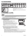
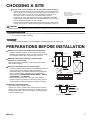
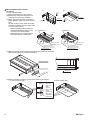
INSTALLATION MANUAL R410A Split series FDXS25F2VEB FDXS35F2VEB FDXS50F2VEB FDXS60F2VEB CE - DECLARACION-DE-CONFORMIDAD CE - DICHIARAZIONE-DI-CONFORMITA CE - ∆HΛΩΣΗ ΣΥΜΜΟΡΦΩΣΗΣ 19 ob upoštevanju določb: 20 vastavalt nõuetele: 21 следвайки клаузите на: 22 laikantis nuostatų, pateikiamų: 23 ievērojot prasības, kas noteiktas: 24 održiavajúc ustanovenia: 25 bunun koşullarına uygun olarak: 07 ** 08 ** 09 ** 10 ** 11 ** 12 ** 11 Information * enligt <A> och godkänts av <B> enligt Certifikatet <C>. 12 Merk * som det fremkommer i <A> og gjennom positiv bedømmelse av <B> ifølge Sertifikat <C>. 13 Huom * jotka on esitetty asiakirjassa <A> ja jotka <B> on hyväksynyt Sertifikaatin <C> mukaisesti. 14 Poznámka * jak bylo uvedeno v <A> a pozitivně zjištěno <B> v souladu s osvědčením <C>. 15 Napomena * kako je izloženo u <A> i pozitivno ocijenjeno od strane <B> prema Certifikatu <C>. Takayuki Fujii Managing Director 5th of November 2012 13 ** 14 ** 15 ** 16 ** 17 ** 18 ** CE - ATITIKTIES-DEKLARACIJA CE - ATBILSTĪBAS-DEKLARĀCIJA CE - VYHLÁSENIE-ZHODY CE - UYUMLULUK-BİLDİRİSİ DICZ*** on valtuutettu laatimaan Teknisen asiakirjan. Společnost DICZ*** má oprávnění ke kompilaci souboru technické konstrukce. DICZ*** je ovlašten za izradu Datoteke o tehničkoj konstrukciji. A DICZ*** jogosult a műszaki konstrukciós dokumentáció összeállítására. DICZ*** ma upoważnienie do zbierania i opracowywania dokumentacji konstrukcyjnej. DICZ*** este autorizat să compileze Dosarul tehnic de construcţie. 19 ** 20 ** 21 ** 22 ** 23 ** 24 ** 25 ** <C> <B> <A> 74736-KRQ/EMC97-4957 DEKRA (NB0344) DAIKIN.TCF.015P12/11-2012 19 Direktive z vsemi spremembami. 20 Direktiivid koos muudatustega. 21 Директиви, с техните изменения. 22 Direktyvose su papildymais. 23 Direktīvās un to papildinājumos. 24 Smernice, v platnom znení. 25 Deǧiştirilmiş halleriyle Yönetmelikler. DICZ*** je pooblaščen za sestavo datoteke s tehnično mapo. DICZ*** on volitatud koostama tehnilist dokumentatsiooni. DICZ*** е оторизирана да състави Акта за техническа конструкция. DICZ*** yra įgaliota sudaryti šį techninės konstrukcijos failą. DICZ*** ir autorizēts sastādīt tehnisko dokumentāciju. Spoločnosť DICZ*** je oprávnená vytvoriť súbor technickej konštrukcie. DICZ*** Teknik Yapı Dosyasını derlemeye yetkilidir. 21 Забележка * както е изложено в <A> и оценено положително от <B> съгласно Сертификата <C>. 22 Pastaba * kaip nustatyta <A> ir kaip teigiamai nuspręsta <B> pagal Sertifikatą <C>. 23 Piezīmes * kā norādīts <A> un atbilstoši <B> pozitīvajam vērtējumam saskaņā ar sertifikātu <C>. 24 Poznámka * ako bolo uvedené v <A> a pozitívne zistené <B> v súlade s osvedčením <C>. 25 Not * <A>’da belirtildiği gibi ve <C> Sertifikasına göre <B> tarafından olumlu olarak değerlendirildiği gibi. 10 Direktiver, med senere ændringer. 11 Direktiv, med företagna ändringar. 12 Direktiver, med foretatte endringer. 13 Direktiivejä, sellaisina kuin ne ovat muutettuina. 14 v platném znění. 15 Smjernice, kako je izmijenjeno. 16 irányelv(ek) és módosításaik rendelkezéseit. 17 z późniejszymi poprawkami. 18 Directivelor, cu amendamentele respective. 16 megfelelnek az alábbi szabvány(ok)nak vagy egyéb irányadó dokumentum(ok)nak, ha azokat előírás szerint használják: 17 spełniają wymogi następujących norm i innych dokumentów normalizacyjnych, pod warunkiem że używane są zgodnie z naszymi instrukcjami: 18 sunt în conformitate cu următorul (următoarele) standard(e) sau alt(e) document(e) normativ(e), cu condiţia ca acestea să fie utilizate în conformitate cu instrucţiunile noastre: 19 skladni z naslednjimi standardi in drugimi normativi, pod pogojem, da se uporabljajo v skladu z našimi navodili: 20 on vastavuses järgmis(t)e standardi(te)ga või teiste normatiivsete dokumentidega, kui neid kasutatakse vastavalt meie juhenditele: 21 съответстват на следните стандарти или други нормативни документи, при условие, че се използват съгласно нашите инструкции: 22 atitinka žemiau nurodytus standartus ir (arba) kitus norminius dokumentus su sąlyga, kad yra naudojami pagal mūsų nurodymus: 23 tad, ja lietoti atbilstoši ražotāja norādījumiem, atbilst sekojošiem standartiem un citiem normatīviem dokumentiem: 24 sú v zhode s nasledovnou(ými) normou(ami) alebo iným(i) normatívnym(i) dokumentom(ami), za predpokladu, že sa používajú v súlade s našim návodom: 25 ürünün, talimatlarımıza göre kullanılması koşuluyla aşağıdaki standartlar ve norm belirten belgelerle uyumludur: 01 Directives, as amended. 02 Direktiven, gemäß Änderung. 03 Directives, telles que modifiées. 04 Richtlijnen, zoals geamendeerd. 05 Directivas, según lo enmendado. 06 Direttive, come da modifica. 07 Οδηγιών, όπως έχουν τροποποιηθεί. 08 Directivas, conforme alteração em. 09 Директив со всеми поправками. 16 Megjegyzés * a(z) <A> alapján, a(z) <B> igazolta a megfelelést, a(z) <C> tanúsítvány szerint. 17 Uwaga * zgodnie z dokumentacją <A>, pozytywną opinią <B> i Świadectwem <C>. 18 Notă * aşa cum este stabilit în <A> şi apreciat pozitiv de <B> în conformitate cu Certificatul <C>. 19 Opomba * kot je določeno v <A> in odobreno s strani <B> v skladu s certifikatom <C>. 20 Märkus * nagu on näidatud dokumendis <A> ja heaks kiidetud <B> järgi vastavalt sertifikaadile <C>. Low Voltage 2006/95/EC Machinery 2006/42/EC ** Electromagnetic Compatibility 2004/108/EC * CE - IZJAVA O SKLADNOSTI CE - VASTAVUSDEKLARATSIOON CE - ДЕКЛАРАЦИЯ-ЗА-ϹЪОТВЕТСТВИЕ 17 m deklaruje na własną i wyłączną odpowiedzialność, że modele klimatyzatorów, których dotyczy niniejsza deklaracja: 18 r declară pe proprie răspundere că aparatele de aer condiţionat la care se referă această declaraţie: 19 o z vso odgovornostjo izjavlja, da so modeli klimatskih naprav, na katere se izjava nanaša: 20 x kinnitab oma täielikul vastutusel, et käesoleva deklaratsiooni alla kuuluvad kliimaseadmete mudelid: 21 b декларира на своя отговорност, че моделите климатична инсталация, за които се отнася тази декларация: 22 t visiška savo atsakomybe skelbia, kad oro kondicionavimo prietaisų modeliai, kuriems yra taikoma ši deklaracija: 23 v ar pilnu atbildību apliecina, ka tālāk uzskaitīto modeļu gaisa kondicionētāji, uz kuriem attiecas šī deklarācija: 24 k vyhlasuje na vlastnú zodpovednosť, že tieto klimatizačné modely, na ktoré sa vzťahuje toto vyhlásenie: 25 w tamamen kendi sorumluluǧunda olmak üzere bu bildirinin ilgili olduǧu klima modellerinin aşaǧıdaki gibi olduǧunu beyan eder: CE - IZJAVA-O-USKLAĐENOSTI CE - MEGFELELŐSÉGI-NYILATKOZAT CE - DEKLARACJA-ZGODNOŚCI CE - DECLARAŢIE-DE-CONFORMITATE 08 estão em conformidade com a(s) seguinte(s) norma(s) ou outro(s) documento(s) normativo(s), desde que estes sejam utilizados de acordo com as nossas instruções: 09 соответствуют следующим стандартам или другим нормативным документам, при условии их использования согласно нашим инструкциям: 10 overholder følgende standard(er) eller andet/andre retningsgivende dokument(er), forudsat at disse anvendes i henhold til vore instrukser: 11 respektive utrustning är utförd i överensstämmelse med och följer följande standard(er) eller andra normgivande dokument, under förutsättning att användning sker i överensstämmelse med våra instruktioner: 12 respektive utstyr er i overensstemmelse med følgende standard(er) eller andre normgivende dokument(er), under forutssetning av at disse brukes i henhold til våre instrukser: 13 vastaavat seuraavien standardien ja muiden ohjeellisten dokumenttien vaatimuksia edellyttäen, että niitä käytetään ohjeidemme mukaisesti: 14 za předpokladu, že jsou využívány v souladu s našimi pokyny, odpovídají následujícím normám nebo normativním dokumentům: 15 u skladu sa slijedećim standardom(ima) ili drugim normativnim dokumentom(ima), uz uvjet da se oni koriste u skladu s našim uputama: Η DICZ*** είναι εξουσιοδοτημένη να συντάξει τον Τεχνικό φάκελο κατασκευής. A DICZ*** está autorizada a compilar a documentação técnica de fabrico. Компания DICZ*** уполномочена составить Комплект технической документации. DICZ*** er autoriseret til at udarbejde de tekniske konstruktionsdata. DICZ*** är bemyndigade att sammanställa den tekniska konstruktionsfilen. DICZ*** har tillatelse til å kompilere den Tekniske konstruksjonsfilen. delineato nel <A> e giudicato positivamente da <B> secondo il Certificato <C>. 07 Σημείωση * όπως καθορίζεται στο <A> και κρίνεται θετικά από το <B> σύμφωνα με το Πιστοποιητικό <C>. 08 Nota * tal como estabelecido em <A> e com o parecer positivo de <B> de acordo com o Certificado <C>. 09 Примечание * как указано в <A> и в соответствии с положительным решением <B> согласно Свидетельству <C>. 10 Bemærk * som anført i <A> og positivt vurderet af <B> i henhold til Certifikat <C>. 06 Nota * DICZ*** is authorised to compile the Technical Construction File. DICZ*** hat die Berechtigung die Technische Konstruktionsakte zusammenzustellen. DICZ*** est autorisé à compiler le Dossier de Construction Technique. DICZ*** is bevoegd om het Technisch Constructiedossier samen te stellen. DICZ*** está autorizado a compilar el Archivo de Construcción Técnica. DICZ*** è autorizzata a redigere il File Tecnico di Costruzione. as set out in <A> and judged positively by <B> according to the Certificate <C>. wie in <A> aufgeführt und von <B> positiv beurteilt gemäß Zertifikat <C>. tel que défini dans <A> et évalué positivement par <B> conformément au Certificat <C>. zoals vermeld in <A> en positief beoordeeld door <B> overeenkomstig Certificaat <C>. como se establece en <A> y es valorado positivamente por <B> de acuerdo con el Certificado <C>. 10 under iagttagelse af bestemmelserne i: 11 enligt villkoren i: 12 gitt i henhold til bestemmelsene i: 13 noudattaen määräyksiä: 14 za dodržení ustanovení předpisu: 15 prema odredbama: 16 követi a(z): 17 zgodnie z postanowieniami Dyrektyw: 18 în urma prevederilor: ***DICZ = Daikin Industries Czech Republic s.r.o. 01 ** 02 ** 03 ** 04 ** 05 ** 06 ** 05 Nota * 04 Bemerk * 03 Remarque * 02 Hinweis * 01 Note * 01 following the provisions of: 02 gemäß den Vorschriften der: 03 conformément aux stipulations des: 04 overeenkomstig de bepalingen van: 05 siguiendo las disposiciones de: 06 secondo le prescrizioni per: 07 με τήρηση των διατάξεων των: 08 de acordo com o previsto em: 09 в соответствии с положениями: EN60335-2-40, 01 are in conformity with the following standard(s) or other normative document(s), provided that these are used in accordance with our instructions: 02 der/den folgenden Norm(en) oder einem anderen Normdokument oder -dokumenten entspricht/entsprechen, unter der Voraussetzung, daß sie gemäß unseren Anweisungen eingesetzt werden: 03 sont conformes à la/aux norme(s) ou autre(s) document(s) normatif(s), pour autant qu'ils soient utilisés conformément à nos instructions: 04 conform de volgende norm(en) of één of meer andere bindende documenten zijn, op voorwaarde dat ze worden gebruikt overeenkomstig onze instructies: 05 están en conformidad con la(s) siguiente(s) norma(s) u otro(s) documento(s) normativo(s), siempre que sean utilizados de acuerdo con nuestras instrucciones: 06 sono conformi al(i) seguente(i) standard(s) o altro(i) documento(i) a carattere normativo, a patto che vengano usati in conformità alle nostre istruzioni: 07 είναι σύμφωνα με το(α) ακόλουθο(α) πρότυπο(α) ή άλλο έγγραφο(α) κανονισμών, υπό την προϋπόθεση ότι χρησιμοποιούνται σύμφωνα με τις οδηγίες μας: FDXS25F2VEB, FDXS35F2VEB, FDXS50F2VEB, FDXS60F2VEB, CE - ERKLÆRING OM-SAMSVAR CE - ILMOITUS-YHDENMUKAISUUDESTA CE - PROHLÁŠENÍ-O-SHODĚ 09 u заявляет, исключительно под свою ответственность, что модели кондиционеров воздуха, к которым относится настоящее заявление: 10 q erklærer under eneansvar, at klimaanlægmodellerne, som denne deklaration vedrører: 11 s deklarerar i egenskap av huvudansvarig, att luftkonditioneringsmodellerna som berörs av denna deklaration innebär att: 12 n erklærer et fullstendig ansvar for at de luftkondisjoneringsmodeller som berøres av denne deklarasjon, innebærer at: 13 j ilmoittaa yksinomaan omalla vastuullaan, että tämän ilmoituksen tarkoittamat ilmastointilaitteiden mallit: 14 c prohlašuje ve své plné odpovědnosti, že modely klimatizace, k nimž se toto prohlášení vztahuje: 15 y izjavljuje pod isključivo vlastitom odgovornošću da su modeli klima uređaja na koje se ova izjava odnosi: 16 h teljes felelőssége tudatában kijelenti, hogy a klímaberendezés modellek, melyekre e nyilatkozat vonatkozik: CE - DECLARAÇÃO-DE-CONFORMIDADE CE - ЗАЯВЛЕНИЕ-О-СООТВЕТСТВИИ CE - OVERENSSTEMMELSESERKLÆRING CE - FÖRSÄKRAN-OM-ÖVERENSTÄMMELSE 01 a declares under its sole responsibility that the air conditioning models to which this declaration relates: 02 d erklärt auf seine alleinige Verantwortung daß die Modelle der Klimageräte für die diese Erklärung bestimmt ist: 03 f déclare sous sa seule responsabilité que les appareils d'air conditionné visés par la présente déclaration: 04 l verklaart hierbij op eigen exclusieve verantwoordelijkheid dat de airconditioning units waarop deze verklaring betrekking heeft: 05 e declara baja su única responsabilidad que los modelos de aire acondicionado a los cuales hace referencia la declaración: 06 i dichiara sotto sua responsabilità che i condizionatori modello a cui è riferita questa dichiarazione: 07 g δηλώνει με αποκλειστική της ευθύνη ότι τα μοντέλα των κλιματιστικών συσκευών στα οποία αναφέρεται η παρούσα δήλωση: 08 p declara sob sua exclusiva responsabilidade que os modelos de ar condicionado a que esta declaração se refere: Daikin Industries Czech Republic s.r.o. CE - DECLARATION-OF-CONFORMITY CE - KONFORMITÄTSERKLÄRUNG CE - DECLARATION-DE-CONFORMITE CE - CONFORMITEITSVERKLARING 3P323721-3A SAFETY PRECAUTIONS The original instructions are written in English. All other languages are translations of the original instructions. • Read these Safety Precautions carefully to ensure correct installation. • This manual classifies the precautions into WARNING and CAUTION. Be sure to follow all the precautions below: they are all important for ensuring safety. WARNING...............Failure to follow any of WARNING is likely to result in such grave consequences as death or serious injury. CAUTION .............. Failure to follow any of CAUTION may in some cases result in grave consequences. • The following safety symbols are used throughout this manual: Be sure to observe this instruction. Be sure to establish an earth connection. Never attempt. • After completing installation, test the unit to check for installation errors. Give the user adequate instructions concerning the use and cleaning of the unit according to the Operation Manual. WARNING • Installation should be left to the dealer or another professional. Improper installation may cause water leakage, electrical shock, or fire. • Install the air conditioner according to the instructions given in this manual. Incomplete installation may cause water leakage, electrical shock, or fire. • Be sure to use only the specified accessories and spare parts for installation work. Failure to use the specified parts may result in the unit falling, water leakage, electric shocks or fire. • Install the air conditioner on a solid base that can support the weight of the unit. An inadequate base or incomplete installation may cause injury in the event the unit falls off the base. • Electrical work should be carried out in accordance with the installation manual and the national electrical wiring rules or code of practice. Insufficient capacity or incomplete electrical work may cause electrical shock or fire. • Be sure to use a dedicated power circuit. Never use a power supply shared by another appliance. • For wiring, use a cable length enough to cover the entire distance with no connection. Do not use an extension cord. Do not put other loads on the power supply, use a dedicated power circuit. (Failure to do so may cause abnormal heat, electric shock or fire.) • Use the specified types of wires for electrical connections between the indoor and outdoor units. Firmly clamp the interconnecting wires so their terminals receive no external stresses. Incomplete connections or clamping may cause terminal overheating or fire. • After connecting interconnecting and supply wiring be sure to shape the cables so that they do not put undue force on the electrical covers or panels. Install covers over the wires. Incomplete cover installation may cause terminal overheating, electrical shock, or fire. • When installing or relocating the system, be sure to keep the refrigerant circuit free from substances other than the specified refrigerant (R410A), such as air. (Any presence of air or other foreign substance in the refrigerant circuit causes an abnormal pressure rise or rupture, resulting in injury.) • If any refrigerant has leaked out during the installation work, ventilate the room. (The refrigerant produces a toxic gas if exposed to flames.) • After all installation is complete, check to make sure that no refrigerant is leaking out. (The refrigerant produces a toxic gas if exposed to flames.) • During pump-down, stop the compressor before removing the refrigerant piping. If the compressor is still running and the shut-off valve is open during pump-down, air will be sucked in when the refrigerant piping is removed, causing abnormal pressure in the freezer cycle which will lead to breakage and even injury. • During installation, attach the refrigerant piping securely before running the compressor. If the compressor is not attached and the shut-off valve is open during pump-down, air will be sucked in when the compressor is run, causing abnormal pressure in the freezer cycle which will lead to breakage and even injury. • When carrying out piping connection, take care not to let air substances other than the specified refrigerant go into refrigeration cycle. Otherwise, it will cause lower capacity, abnormal high pressure in the refrigeration cycle, explosion and injury. • Be sure to establish an earth. Do not earth the unit to a utility pipe, arrester, or telephone earth. Incomplete earth may cause electrical shock, or fire. A high surge current from lightning or other sources may cause damage to the air conditioner. • Be sure to install an earth leakage breaker. Failure to install an earth leakage breaker may result in electric shocks, or fire. CAUTION • Do not install the air conditioner in a place where there is danger of exposure to inflammable gas leakage. If the gas leaks and builds up around the unit, it may catch fire. • Establish drain piping according to the instructions of this manual. Inadequate piping may cause flooding. • Tighten the flare nut according to the specified method such as with a torque wrench. If the flare nut is tightened too hard, the flare nut may crack after a long time and cause refrigerant leakage. • Only handle the indoor unit with gloves. English 1 ACCESSORIES Clamp metal Insulation for fitting 1 pc. 1 each Washer for Drain hose hanging bracket Sealing pad Large and small 3 pcs. 1 each (only for 50-60 type) 1 pc. 1 pc. Sealing material Clamp 2 pcs. 6 pcs. 8 pcs. Washer Screws for fixing plate duct flanges 1 set 1 set 4 pcs. 24 pcs. 2 large for gas pipe Large 1 small for liquid pipe Stored in outlet vent Optional accessories Air fillter 1 pc. Small Hanger (right) insulation [ Other ] • Operation manual • Installation manual ・ This indoor unit requires one of remote controllers. ・ There are two type of remote controller: wired and wireless. Select a remote controller according to customers request and install in an appropriate place Refer to catalogues and technical literature for selecting a suitable remote controller CHOOSING A SITE • Before choosing the installation site, obtain user approval. Indoor unit Caution • When moving the unit during or after unpacking, make sure to lift it by holding its lifting lugs. Do not exert any pressure on other parts, especially the refrigerant piping, drain piping and flange parts. Wear protective gears (gloves and so on) when installing the unit. • If you think the humidity inside the ceiling might exceed 30°C and RH80%, reinforce the insulation on the unit body. Use glass wool or polyethylene foam as insulation so that the thickness is more than 10mm and fits inside the ceiling opening. 300 or more Maintenance space 20 or more Ceiling If there is no ceiling Control box *H= 240 or 2500 or more more Optimum air distribution is ensured. The air passage is not blocked. Condensate can drain properly. The ceiling is strong enough to bear the weight of the indoor unit. A false ceiling does not seem to be at an incline. Sufficient clearance for maintenance and servicing is ensured. Piping between the indoor and outdoor units is within the allowable limits. (Refer to the installation manual for the outdoor unit.) • The indoor unit, outdoor unit, power supply wiring and transmission wiring is at least 1 meter away from televisions and radios. This prevents image interference and noise in electrical appliances. (Noise may be generated depending on the conditions under which the electric wave is generated, even if a one-meter allowance is maintained.) • The equipment is not intended for use in a potentially explosive atmosphere. 200 • • • • • • • Floor surface (length : mm) Use suspension bolts to install the unit. Check whether or not the ceiling is strong enough to support the weight of the unit. If there is a risk that the ceiling is not strong enough, reinforce the ceiling before installing the unit. Select the *H dimension such that a downward slope of at least 1/100 is ensured as indicated in “DRAIN PIPING WORK”. • To avoid contact with the fan, one of the following precaution actions must be taken: - Install the unit as high as possible at a minimum bottom height of 2.7 m. - Install the unit as high as possible at a minimum bottom height of 2.5 m in case the fan is externally screened by parts which can be removed without the aid of tools (e.g. false sealing, grill ... ). - Install the unit with ducting and grill which can only be removed with the aid of tooling. It shall be installed so that it gives adequate protection against touching the fan. If a maintenance panel exists in the ducting, it shall only be possible to remove the panel by the aid of tooling to avoid contact with the fan. The protection shall be according to relevant European and local legislation. There are no restrictions concerning the installation height. 2 English CHOOSING A SITE Select the signal receiver mounting location according to the following conditions: • Install the signal receiver, which has a built-in temperature sensor, near the intake vent where there is convection of air and it can get an accurate reading of the room’s temperature. If the intake vent is in another room or the unit cannot be installed near the intake vent for any other reason, install it 1.5m above the floor on a wall where there is convection. • In order to get an accurate reading of the room’s temperature, install the signal receiver in a location where it is not exposed directly to cold or hot air from the air discharge grille or to direct sunlight. • Since the receiver has a built-in light receptor to receive signals from the wireless remote controller, do not mount it in a location where the signal may be blocked by a curtain, etc. Air discharge grille: Wooden or plastic grille is recommended because condensation may occur depending on humidity conditions. Caution If the signal receiver is not installed in a location where there is convection of air, it may be unable to get an accurate reading of the room’s temperature. Wireless remote controller • Turn on all the fluorescent lamps in the room, if any, and find the site where remote controller signals are properly received by the indoor unit (within 4 metres). Outdoor unit • For outdoor unit installation, see the installation manual supplied with the outdoor unit. PREPARATIONS BEFORE INSTALLATION Relation of the unit to the suspension bolt positions. 620 • Install the inspection opening on the control box side where maintenance and inspection of the control box are easy. Install the inspection opening also in the lower part of the unit. Ceiling Air inlet A Air discharge (length : mm) (See the technical documentation for the range of the external static pressure setting.) Open the installation hole. (Pre-set ceilings) • Once the installation hole is opened in the ceiling where the unit is to be installed, pass refrigerant piping, drain piping, transmission wiring, and remote controller wiring (unneeded if using a wireless remote controller) to the unit’s piping and wiring holes.See “REFRIGERANT PIPING WORK”, “DRAIN PIPING WORK”, and “WIRING”. • After opening the ceiling hole, make sure ceiling is level if needed. It might be necessary to reinforce the ceiling frame to prevent shaking.Consult an architect or carpenter for details. 620 Control box 450×450 (Inspection opening size) Model 15-20-25-32 type 40-50 type 63 type (length: mm) A B 750 740 950 940 1150 1140 Install the suspension bolts. (Use W3/8 to M10 suspension bolts.) Use a hole-in-anchor, sunken insert, sunken anchor for existing ceilings, and a sunken insert, sunken anchor or other part to be procured in the field to reinforce the ceiling to bearing the weight of the unit. (Refer to Fig.) SERVICE SPACE A Suspension bolt pitch B (Suspension bolt pitch) Make sure the range of the unit’s external static pressure is not exceeded. 500 Allow view Inspection door (Ceiling opening) Ceiling slab Anchor bolt Long nut or turn-buckle Suspension bolt Indoor unit Note: All the above parts are field supplied. English 3 Mount chamber lid and air filter (accessory). In case of bottom suction. (1)Remove the chamber lid. (7 locations) (2)Reattach the removed chamber lid in the orientation shown in Fig.(7 locations) (3)Attach sealing pad as shown in the figure below. (Stored in outlet vent) (only for 50-60 type) (In order to take in the air inside the ceiling, and when not taking in air from outdoor air, it is not necessary to stick.) • Attach the sealing pad (accessory) to the plate metal sections which are not (3) covered by anti-sweat material. • Make sure there are no gaps between the different pieces of sealing pad. (1) (2) Air inlet Chamber lid Chamber lid Air inlet Air discharge Air discharge Sealing pad (Small) (accessory) Sealing pad (Small) (accessory) Air inlet Air inlet Air discharge Sealing pad (Large) (accessory) Anti-sweat material included with the product Air discharge Sealing pad (Lar (accessory) Anti-sweat material included with the product For rear intake type For bottom intake type (4)Attach the hanger (right) insulation to the right hanger. (Stored in outlet vent) (See the below figure for the sticking base line.) Hanger bracket (right) Hanger (right) insulation ARROW VIEW Slit c Sti kin gb as in el e (5)Attach the air filter (accessory) in the manner shown in the diagram. In case of bottom side In case of back side Main unit Force Filter Force 4 Attach the filter to the main unit while pushing down on the bends. (2 bends for 25-35 type, 3 bends for 50-60 type) English INDOOR UNIT INSTALLATION As for the parts to be used for installation work, be sure to use the provided accessories and specified parts designated by our company. Install the indoor unit temporarily. • Attach the hanger bracket to the suspension bolt. Be sure to fix it securely by using a nut and washer from the upper and lower sides of the hanger bracket. (Refer to Fig.) [ Securing the hanger bracket ] [ How to secure washers ] Part to be procured in the field Washer for hanging bracket (accessory) [ PRECAUTION ] Since the unit uses a plastic drain pan, prevent welding spatter and other foreign substances from entering the outlet hole during installation. Hanger bracket Insert below washer Washer fixing plate (accessory) Tighten (double nut) Adjust the height of the unit. Check the unit is horizontally level. Level Vinyl tube Caution Make sure the unit is installed level using a level or a plastic tube filled with water.In using a plastic tube instead of a level ,adjust the top surface of the unit to the surface of the water at both ends of the plastic tube and adjust the unit horizontally.(One thing to watch out for in particular is if it is installed so that the slope is not in the direction of the drain piping,as this might cause leaking.) Tighten the upper nut. Mounting the remote controller. Refer to the “installation manual of the remote controller” supplied with remote controller. English 5 For heat pump: If your feet feel cold when using the heating function, it is recommended that the air discharge grille shown at below be attached. 45° (Adjustable angle) OUTDOOR UNIT INSTALLATION Install as described in the installation manual supplied with the outdoor unit. REFRIGERANT PIPING WORK See the installation manual supplied with the outdoor unit. 1. FLARING THE PIPE END 1) Cut the pipe end with a pipe cutter. 2) Remove burrs with the cut surface facing downward so that the chips do not enter the pipe. 3) Put the flare nut on the pipe. 4) Flare the pipe. 5) Check that the flaring is properly made. (Cut exactly at right angles.) Remove burrs Flaring Set exactly at the position shown below. A Die A Flare tool for R410A Conventional flare tool Clutch-type Clutch-type (Ridgid-type) Wing-nut type (Imperial-type) 0-0.5mm 1.0-1.5mm 1.5-2.0mm Check Flare’s inner surface must be flaw-free. The pipe end must be evenly flared in a perfect circle. Make sure that the flare nut is fitted. Warning Do not use mineral oil on flared part. Prevent mineral oil from getting into the system as this would reduce the lifetime of the units. Never use piping which has been used for previous installations. Only use parts which are delivered with the unit. Do never install a drier to this R410A unit in order to guarantee its lifetime. The drying material may dissolve and damage the system. Incomplete flaring may cause refrigerant gas leakage. 2. REFRIGERANT PIPING 1) To prevent gas leakage, apply refrigeration machine oil on both inner and outer surfaces of the flare. (Use refrigeration oil for R410A) 2) Align the centres of both flares and tighten the flare nuts 3 or 4 turns by hand. Then tighten them fully with the torque wrenches. • Use torque wrenches when tightening the flare nuts to prevent damage to the flare nuts and escaping gas. Ø9.5 33-39N•m Flare nut tightening torque Gas side Ø12.7 50-60N•m Liquid side Ø6.4 15-17N•m Caution Overtightening may damage the flare and cause leaks. 6 English REFRIGERANT PIPING WORK 3) After the work is finished, make sure to check that there is no gas leak. Coat here with refrigeration machine oil Torque wrench Spanner Flare nut Piping union 4) After checking for gas leaks, be sure to insulate the pipe connections. • Insulate using the insulation for fitting included with the liquid and gas pipes. Besides, make sure the insulation for fitting on the liquid and gas piping has its seams facing up. (Tighten both edges with clamp.) • For the gas piping, wrap the medium sealing pad over the insulation for fitting (flare nut part). Gas Piping Insulation Procedure Piping insulation material (main unit) Insulation for fitting (accessory) Attach to base Flare nut connection Turn seams up Main unit Measure the length of the gas pipe as you will have to cover it with the sealing tape. Small sealing pad (accessory) Main unit Clamp (accessory) Piping insulation material (Field supplied) Liquid Piping Insulation Procedure Insulation for fitting (accessory) Piping insulation material (main unit) Liquid pipe Gas pipe Flare nut connection Attach to base Turn seams up Main unit Clamp (accessory) Wrap the sealing tape around the gas pipe. Piping insulation material (Field supplied) Caution Be sure to insulate any field piping all the way to the piping connection inside the unit. Any exposed piping may cause condensation or burns if touched. Cautions on Pipe Handling Wall • Protect the open end of the pipe against dust and moisture. (Tighten both edges with clamp.) • All pipe bends should be as gentle as possible. Use a pipe bender for bending. (Bending radius should be 30 to 40mm or larger.) Be sure to place a cap. Rain If no flare cap is available, cover the flare mouth with tape to keep dirt or water out. Selection of Copper and Heat Insulation materials When using commercial copper pipes and fittings, observe the following: • Insulation material: Polyethylene foam Heat transfer rate: 0.041 to 0.052W/mK (0.035 to 0.045kcal/mh°C) Refrigerant gas pipe’s surface temperature reaches 110°C max. Choose heat insulation materials that will withstand this temperature. • Be sure to insulate both the gas and liquid piping and to provide insulation dimensions as below. Gas side 25/35 class 50/60 class O.D. 9.5mm O.D. 12.7mm Liquid side O.D. 6.4mm Gas pipe thermal insulation 25/35 class 50/60 class Liquid pipe thermal insulation I.D. 12-15mm I.D. 14-16mm I.D. 8-10mm Thickness 0.8mm Also, when subject to high humidity, heat insulation of the refrigerant piping (the unit piping and branch piping) must be further reinforced. Reinforce the insulation when installing the unit near bathrooms, kitchens, and other similar locations. Refer to the following: • 30°C, more than 75% RH: 20mm Min. in thickness If the insulation is not sufficient, condensation may form on the surface of the insulation. • Use separate thermal insulation pipes for gas and liquid refrigerant pipes. English Thickness 10mm Min. Inter-unit wiring Gas pipe Gas pipe insulation Finishing tape Liquid pipe Liquid pipe insu Drain hose 7 DRAIN PIPING WORK Caution Make sure all water is out before making the duct connection. Install the drain piping. Drain pipe connection hole • Make sure the drain works properly. • The diameter of the drain pipe should be greater than or equal to the diameter of the connecting pipe (vinyl tube; pipe size: 20mm; outer dimension: 26mm). Refrigerant pipes Connect the drain pipe after removing the rubber cap and insulation tubing attached to the connection hole. • Keep the drain pipe short and sloping downwards at a gradient of at least 1/100 to prevent air pockets from forming. Caution Water accumulating in the drain piping can cause the drain to clog. • To keep the drain tube from sagging, space hanging wires every 1 to 1.5m. • Use the drain hose and the metal clamp. Insert the drain hose fully into the drain socket and firmly tighten the metal clamp with the upper part of the tape on the hose end. Tighten the metal clamp until the screw head is less than 4mm from the hose. • The two areas below should be insulated because condensation may form there causing water to leak. • Drain piping passing indoors Large sealing pad Clamp metal • Drain sockets (accessory) (accessory) Referring the figure below, insulate the metal clamp and drain hose using the Clamp metal included large sealing pad. (accessory) Tape Drain hose ≤4mm PRECAUTIONS Drain piping connections • Do not connect the drain piping directly to sewage pipes that smell of ammonia. The ammonia in the sewage might enter the indoor unit through the drain pipes and corrode the heat exchanger. • Do not twist or bend the drain hose, so that excessive force is not applied to it. (This type of treatment may cause leaking.) After piping work is finished, check drainage flows smoothly. • Gradually insert approximately 1L of water into the drain pan to check drainage in the manner described below. • Gradually pour approximately 1L of water from the outlet hole into the drain pan to check drainage. • Check the drainage. Air outlet Portable pump Bucket Refrigerant pipes Drain outlet 8 English INSTALLING THE DUCT Connect the duct supplied in the field. Air inlet side • Attach the duct and intake-side flange (field supply). • Connect the flange to the main unit with accessory screws (in 16, 20 or 24 positions). • Wrap the intake-side flange and duct connection area with aluminum tape or something similar to prevent air escaping. Caution When attaching a duct to the intake side, be sure also to attach an air filter inside the air passage on the intake side. (Use an air filter whose dust collecting efficiency is at least 50% in a gravimetric technique.) Outlet side • Connect the duct according to the inside of the outlet-side flange. • Wrap the outlet-side flange and the duct connection area with aluminum tape or something similar to prevent air escaping. Flange (Field supply) Main unit Connection screw (accessory) Flange Insulation material (Field supply) Aluminum tape (Field supply) Aluminum tape (Field supply) Air inlet side Outlet side Caution • Be sure to insulate the duct to prevent condensation from forming. (Material: glass wool or polyethylene foam, 25mm thick) • Use electric insulation between the duct and the wall when using metal ducts to pass metal laths of the net or fence shape or metal plating into wooden buildings. English 9 WIRING See the installation manual supplied with the outdoor unit. HOW TO CONNECT WIRINGS. • Wire only after removing the control box lid as shown in the Fig. Control box lid Power supply wiring Earth wire • Make sure to let a wire go through a wire penetration area. • After wiring, seal the wire and wire penetration area to prevent moisture and small creatures from the outside. • Wrap the strong and weak electric lines with the sealing material as shown in the figure below. (Otherwise, moisture or small creatures such as insects from the outside may cause short-circuit inside the control box.) Attach securely so that there are no gaps. Sealing material (accessory) Wiring Diagram (Rear) ∗Remote controller wiring Wiring through hole Wire Outside unit Inside unit [How to adhere it] Caution • When clamping the wiring, use the included clamping material as shown in the Fig. to prevent outside pressure being exerted on the wiring connections and clamp firmly. • When doing the wiring, make sure the wiring is neat and does not cause the control box lid to stick up, then close the cover firmly. When attaching the control box lid, make sure you do not pinch any wires. • Outside the machine, separate the weak wiring (remote controller wiring) and strong wiring (earth wire and power supply wiring) at least 50mm so that they do not pass through the same place together. Proximity may cause electrical interference, malfunctions, and breakage. [ PRECAUTION ] • See also the “Electrical Wiring Diagram Nameplate” when wiring the unit for electrical power. [ Connecting electrical wiring ] • Power supply wiring and Earth wire Remove the control box lid. Next, pull the wires into the unit through the wiring through hole and connect to the power wiring terminal block (4P). Be sure to put the part of the sheathed vinyl into the control box. Indoor PCboard (ASSY) Clamps (for preventing slippage) *Transmission wiring *Remote controller wiring * Do not connect power supply wiring here. That may cause malfunction Power supply wiring Earth wire Control box Control box 㽢 䕿 Power supply wiring/Earth wire 10 English Warning Do not use tapped wires, stand wires, extensioncords, or starbust connections, as they may cause overheating, electrical shock, or fire. To outdoor unit When wire length exceeds 10m, use 2.0mm wires. Indoor unit 1 2 3 1.6mm or 2.0mm H07RN-F TRIAL OPERATION AND TESTING Trial operation and testing (1) Measure the supply voltage and make sure that it falls in the specified range. (2) Trial operation should be carried out in either cooling or heating mode. Trial operation from remote controller (1) Press ON/OFF button to turn on the system. (2) Simultaneously press center of TEMP button and MODE button. (3) Press MODE button twice. (“ ” will appear on the display to indicate that Trial Operation mode is selected.) (4) Trial run mode terminates in approx. 30 minutes and switches into normal mode. To quit a trial operation, press ON/OFF button. For Heat pump. In cooling mode, select the lowest programmable temperature; in heating mode, select the highest programmable temperature. • Trial operation may be disabled in either mode depending on the room temperature. • After trial operation is complete, set the temperature to a normal level (26°C to 28°C in cooling mode, 20°C to 24°C in heating mode). • For protection, the system disables restart operation for 3 minutes after it is turned off. (3) Carry out the test operation in accordance with the Operation Manual to ensure that all functions and parts, are working properly. * The air conditioner requires a small amount of power in its standby mode. If the system is not to be used for some time after installation, shut off the circuit breaker to eliminate unnecessary power consumption. * If the circuit breaker trips to shut off the power to the air conditioner, the system will restore the original operation mode when the circuit breaker is turned on again. Test items Test items Indoor and outdoor units are installed properly on solid bases. No refrigerant gas leaks. Refrigerant gas and liquid pipes and indoor drain hose extension are thermally insulated. Draining line is properly installed. System is properly earthed. The specified wires are used for interconnecting wire connections. Indoor or outdoor unit’s air inlet or discharge has clear path of air. Shut-off valves are opened. Indoor unit properly receives remote controller commands. English Symptom (diagnostic display on RC) Check Fall, vibration, noise Incomplete cooling/heating function Water leakage Water leakage Electrical leakage Inoperative or burn damage Incomplete cooling/heating function Inoperative 11 WIRING DIAGRAM : FIELD WIRING : CONNECTOR : WIRE CLAMP : PROTECTIVE EARTH (SCREW) : LIVE : NEUTRAL L N BLK BLU BRN GRY ORG PNK : BLACK : BLUE : BROWN : GREY : ORANGE : PINK PRP RED WHT YLW GRN : PURPLE : RED : WHITE : YELLOW : GREEN INDOOR UNIT RECEIVER/DISPLAY UNIT A1P........................ PRINTED CIRCUIT BOARD A2P ........................PRINTED CIRCUIT BOARD C105...................... CAPACITOR A3P ........................PRINTED CIRCUIT BOARD PS.......................... POWER SUPPLY CIRCUIT BS1 ........................PUSH BUTTON (ON/OFF) RC ......................... RECEIVING CIRCUIT H1P ........................LIGHT EMITTING DIODE (ON-RED) TC.......................... TRANSMISSION CIRCUIT H2P ........................LIGHT EMITTING DIODE (FILTER DING-RED) HAP ....................... LIGHT EMITTING DIODE (SERVICE MONITORING –GREEN) H3P ........................LIGHT EMITTING DIODE (TIMER-GREEN) M1F ....................... MOTOR (FAN) H4P ........................LIGHT EMITTING DIODE (DEFROST-ORANGE) SS1 ........................SELECTOR SWITCH (MAIN/SUB) M1P ....................... MOTOR (DRAIN PUMP) SS2 ........................SELECTOR SWITCH (WIRELESS ADRESS SET) Q1DI ...................... EARTH LEAK DETECTOR R1T........................ THERMISTOR (AIR) ADAPTOR FOR WIRING R2T, R3T ............... THERMISTOR (COIL) KHuR .....................MAGNETIC RELAY S1L ........................ FLOAT SWITCH KFR ........................MAGNETIC RELAY SS1........................ SELECTOR SWITCH (EMERGENCY) V1R ....................... DIODE BRIDGE KCR .......................MAGNETIC RELAY F1U ........................FUSE((B),5A,250V) X1M ....................... TERMINAL BLOCK (CONTROL) F2U ........................FUSE((B),5A,250V) X2M ....................... TERMINAL BLOCK (POWER SUPPLY) Z1C........................ FERRITE CORE (NOISE FILTER) Z1F ........................ NOISE FILTER CONNECTOR FOR OPTIONAL PARTS X24A ......................CONNECTOR (WIRELESSREMOTE CONTROLLER) X33A ......................CONNECTOR (ADAPTOR FOR WIRING) X35A ......................CONNECTOR (POWER SUPPLY CONNECTOR) WIRED REMOTE CONTROLLER R1T ........................THERMISTOR (AIR) SS1 ........................SELECTOR SWITCH (MAIN/SUB) WIRED REMOTE CONTROLLER : Wired remote controller (OPTIONAL ACCESSORY) : (Optional accessory) SWITCH BOX (INDOOR) : Switch box (indoor) TRANSMISSION WIRING : Transmission wiring CENTRAL REMOTE CONTROLLER : Central remote controller INPUT FROM OUTSIDE : Input from outside NOTE 12 1. USE COPPER CONDUCTORS ONLY. 2. WHEN USING THE CENTRAL REMOTE CONTROLLER, SEE MANUAL FOR CONNECTION TO THE UNIT. 3. WHEN CONNECTING THE INPUT WIRES FROM OUTSIDE, FORCED "OFF" OR "ON/OFF" CONTROL OPERATION CAN BE SELECTED BY THE REMOTE CONTROLLER. SEE INSTALLATION MANUAL FOR MORE DETAILS. 4. REMOTE CONTROLLER MODEL VARIES ACCORDING TO THE COMBINATION SYSTEM, CONFIRM ENGINEERING DATA AND CATALOGS, ETC. BEFORE CONNECTING. English 4P325054-1 2012.07 Copyright 2012 Daikin