1
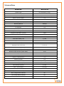
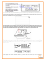
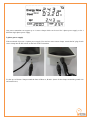
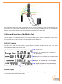
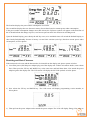
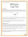
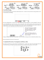
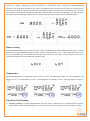
User Manual
Energy Genius Basic RTD
Thank you for purchasing this Energy Genius wireless electricity monitor. This guide will help you set up the wireless
monitoring system quickly and easily.
What are included in the standard package?
Your package should contain:
1pc of Display Unit
1pc of Power Adapter for the Display Unit
1pc of 1-way Power Transmitter
1pc of Sensor Clamp fixed on the transmitter
1pc of RJ45-USB Data Cable (3m) - Optional
as displayed in the right photo
and 1pc of the User Manual
The monitor can support up to 15pcs of 1-way
power transmitters and each transmitter can
support up to 3pcs of sensor clamps.
If you’ve bought extra transmitters and sensor clamps, please put them in appropriate place before installation.
If any parts are missing, please contact your seller immediately.
Before installation, please pay attention to following information:
1) Please read all instructions before you use the monitoring system
2) Please shake the Display Unit and the Power Transmitter first before installation. In case you hear any sound from
inside of the part, please don’t use it. Please replace it with your seller.
3) Do not allow children or people unfamiliar with these instructions to use your monitoring system.
4) Keep the monitor, transmitter and sensor clamp away from sources of heat, water or any other liquid.
5) Place the monitor, transmitter and sensor clamp where children can not touch or pull.
6) Don’t try to disassemble or modify any parts of the monitoring system. In case of problem, please consult your seller
or contact…..
7) Don’t use the monitoring system if you find your electric wire in abnormal conditions, such as loose wire, exposed
copper wire, burnt mark on wire insulation layer, holes on wire layer or damage on electric meter. In case of such
abnormalities, please consult a professional electrician immediately.
8) Periodically check all wires and components to ensure there is no damage.
9) Use a dry cloth to clean. Don’t use solvent, abrasive cleaners or water.
Technical Data
Model No.
RCS-S22A
System Type
Uni-directional (1-way)
LCD Screen Size (mm)
79*48.5
Portability of the Display Unit
Portable, with built-in battery
With DC Power Adapter
Yes
Wireless Transmission
Yes
Indoor Minimum Covering Distance (over partitions)
30m
Mounting Options
Desktop
PC Link
Yes, with RJ45 to USB data cable
PC Software
Yes
Compatibility with 3-phase
Yes
Supported coding channels
15 channels
Supported transmitter quantity
15pcs
Supported sensor clamps quantity
3pcs per transmitter
Sensor Clamp Diameter
10mm and 25mm optional
Transmitter Battery Life
2 years
Signal Interval
8 seconds
Data Accuracy
1A—100A, 7% for 10mm and 18mm clamp
Displayed Cost Currencies
£, Euro, $
Customizable Voltage Range
80-265V
Maximum Input Current (under 220V)
60A or 100A
Minimum Input Current (under 220V)
0.2A
KW reading in real time
Yes
Cost Forecast
Per Hour/Day/Month
Display of CO2 Emission
Yes
Memory function
Yes
KWH History Reading
Yes, 30 days Energy Consumption
Automatic Switching of Display Modes
No
Data Storage Capacity
2 years
Date / Time Display
Time Only
Indoor Temperature Display
Yes
Compatible with Economy 7
Yes
Over-voltage Alarm Indicator
No
Low-voltage Alarm Indicator
No
Over-loading Alarm Indicator
No
System Installation
Step 1: Attach the Display Unit to a power supply socket.
Use the power adapter to attach the Display Unit to a power supply socket nearby. After being connected to power
supply, the LCD screen of the Display Unit will display as below right photo, where the “Energy Now” value is
dashes.
Now keep the Display Unit powered on at all times.
Step 2: Make the 1-way Power Transmitter start to work
Keep the Transmitter as close to the Display Unit as possible. Pull out the clear plastic tab (marked with
“REMOVE BEFORE USING”) from the back of the transmitter. The tab is an insulation sheet, once it is pulled out,
the built-in batteries will make the transmitter start to work immediately.
Step 3: Pairing of the Display Unit with the Transmitter
Press the UP/DOWN key of the Display Unit to choose the coding channel (CH01-CH15, beside the CLOCK
symbol) which is to be used to pair with the transmitter, for example, in below photo, CH03 is chosen as the
channel number.
Let’s start from CH01. Press the UP/DOWN key to choose CH01, then press the DOWN key and hold it there for 3
seconds. Release the DOWN key when the antenna icon is flashing at the top right corner of the LCD screen, as
below photo. The Display Unit is now ready for pairing.
Keep the transmitter close to the Display Unit in the same room. Make sure that the plastic tab has been removed. Now
use a slim stick to push into the pairing hole of the transmitter (as shown in below photo) and hold it there until the
LED light of the transmitter flashes quickly. The transmitter is now starting to pair with the Display Unit.
The pairing may take up to 60 seconds. When the pairing is successfully finished, the antenna icon stops flashing
and stays on the top right corner of the LCD screen. The “Energy Now” value on the LCD screen will change from
dashes to 0 Watt.
If the Display Unit and the Transmitter failed to get paired within 60 seconds, they will exit the pairing
automatically. Please try pairing again.
If more 1-way Power Transmitters need to be paired, just choose different channel number and repeat in the same
way. Up to 15pcs of Transmitter can be paired with one RCS-S22A Display Unit. The transmitter sends pairing
signal for 60 seconds once it is in pairing mode, so please wait for 60 seconds before you pair the next transmitter.
Note: If more than one transmitter is to be paired, prepare a note and write down the channel numbers and their
corresponding transmitters for future reminder.
Step 4: Installation of the 1-way Transmitter and the Sensor Clamp
The transmitter already has a sensor clamp fixed together with it. You may choose to put the Transmitter in a dry
place near the monitored object or stick the Transmitter on the wall near the monitored object.
Fix the Sensor Clamp around the live wire or the null line (also called zero line) of the monitored object, just as
below photo is showing (Don’t fix the clamp around the ground wire). Make sure to let the wire pass through the
clamp.
Note: There are three kinds of optional sensor clamp, one with the diameter of 10mm (as shown in above photo); the others are
18mm and 25mm (as shown in below photo).
The Sensor Clamp immediately starts to sensor the current and the energy monitoring system starts to work. The
LCD screen of the Display Unit should now display the power consumption of the monitored object in real time,
and the third line will display the power change, for example as below photo.
One power transmitter can support up to 3 sensor clamps which can be used for 3-phase power supply or for 3
different single-phase power supply.
3-phase power supply
If the monitored object use a 3-phase power supply. You need two more sensor clamps. Attach the DC plug of each
sensor clamp into the DC sockets on the back of the Transmitter.
Fix the 3pcs of Sensor Clamps around the lines of Phase-A, B and C (Don’t fix the clamps around the ground wire
and neutral wire).
Note: Under single phase power supply, one transmitter can work on up to three objects by using 3pcs sensor clamps fixed
around the live wire or the null line of each object (if they are close enough to the transmitter). In this case, the information
displayed on the screen of the Display Unit for this transmitter is a total value of these three objects.
Settings and Functions of the Display Unit
After the Display Unit and the Transmitter have been successfully paired, we need to make some settings of the
LCD screen so that we can get desired correct information from the Display Unit.
Full LCD Symbols
First have a look at the full LCD symbols to get an idea of the meaning of each word and value for the Main
Display Interface and how the monitor works.
Default Display
Also have a look at an example of the Default Display as below photo. The Default Display is what the user usually
sees from the LCD in normal working mode.
The first line displays the power under consumption in real time.
The second line displays the cost forecast in money for one hour based on current power under consumption.
If the power under consumption changes more than 30watt, the Up/Down symbol will appear on the third line of
the LCD and indicate the change of power, cost forecast per hour and CO2 emission in switching mode.
Upon the Default Display, press shortly the OK key once, twice and third times will switch the Default Display to
show hourly/Daily/Monthly forecast of money cost and CO2 emission (unit: kgs) based on current power under
consumption, as below photos.
Resetting and Data Clearance
If the unit needs to be reset and the data needs to be cleared from the display unit, please operate as below:
1) Cut off the power (Pull the power adapter plug out of the display unit. If there are batteries inside, remove them
first). Then press the UP key and DOWN key at the same time and hold them there. Now attach the power
adapter again to the display unit. The LCD screen will display the full LCD symbols as below photo:
2) Now release the UP key and DOWN key.. The LCD screen will display programming version number, as
below photo:
3) Then pull out the power adapter and re-attach the power adapter. The LCD will display Energy Now value as
dashes. Up to now the data clearance is finished. The transmitters need to be paired again with the Display Unit
and all settings need to re-done.
Voltage Setting
Upon the Default Display, please press UP/DOWN key to select the Channel number that need to set the voltage.
When the desired channel number appears, press at the same time the OK key and the DOWN key and hold them
there for about 3 seconds until the LCD enters into the voltage setting interface as per below photo where the first
number "1" of 120 (maybe “2” of 230) is flashing.
Please use the UP/DOWN key to scroll to the correct number (0-6) and press OK key for the first number. Then
you will see the second number flashing, please scroll to the correct number (0-9) and press OK key for the second
number. Do the same for the last number to exit the voltage setting.
Every Channel can set a different voltage. If the object is single phase, please just set the single voltage. For
3-phase, the voltage set should be the (line-to-line voltage), not (line-to-neutral voltage). And (line-to-line
voltage)=1.732*(line-to-neutral voltage).
Coding Channels View
If more than one Transmitter is paired with the energy Display Unit, the Default Display displays the total data of
all paired transmitters. To view the information of a single transmitter, press the UP/DOWN key upon the Default
Display to tune into different coding channels for different Transmitters. The CLOCK value will accordingly
change to display the channel numbers for all paired transmitters (from CH01-CH15). And the values on the LCD
screen will immediately change accordingly to provide real time information for the tuned channels.
Pressing the DOWN key upon CH01 or pressing the UP key upon CH15 will return the LCD to the Default Display.
Otherwise the LCD will stay in the display for the selected channel.
Upon the display of single channel viewing, press shortly the OK key once, twice and third times will switch the
display to show hourly/Daily/Monthly forecast of money cost and CO2 emission (unit: kgs) based on current power
under consumption for the selected channel.
Clock/Date Setting
Upon the Default Display, press OK key and hold it there for 3 seconds to enter into the time setting interface. First
it is the HOUR value flashing.
Press the UP/DOWN key to get the correct value for the hour, then press OK key to switch to MINUTE value and
use the UP/DOWN key to get the correct value for the minute. Press OK key and the LCD will enter into the
setting interface for Data. Please set the flashing value in turn of correct Year, Month and Date and press OK key to
confirm each one. The confirmation of the data will return the LCD to the Default Display.
During the setting, if idle time of no operation is over 60 seconds, the setting will exit automatically without saving.
Please note that the clock runs in 24-hour mode.
Accumulated Electricity Consumption and History Data
Press OK key and UP key at the same time and hold them for 3 seconds. The LCD screen will display the total
accumulated energy consumption and CO2 emission (unit: kgs) starting from the pairing, as below photo.
Upon above display, continuously press the DOWN key will lead the LCD to display the total accumulated
electricity cost spent from the pairing, the energy consumption and CO2 emission (unit: kgs) for current day, the
electricity cost spent for current day, the energy consumption and CO2 emission for current month, the electricity
cost spent for current month, respectively and in turn, as below photos. Press the OK during this viewing will return
the LCD to the Default Display. Idleness of key operation for 60seconds will also return to Default Display.
Buzzer Setting
Upon the Default Display, press at the same time UP key and DOWN key and hold them there for about 3 seconds
until the LCD screen displays the Buzzer status. “bOFF” means the Buzzer is off. “bON” means the Buzzer is on.
Press the UP/DOWN key to switch the Buzzer status. Press OK key to exit setting. If key operation is idle for 60
seconds, the setting will exit automatically without saving.
Temperature
The temperature that can be displayed on the screen is -9~50℃. For temperature under -9℃, the temperature will
display as LO℃. For temperature over 50℃, the temperature will display as HO℃. The temperature accuracy is
±2℃.
Electricity Tariff Setting
1) Currency Setting: Upon the Default Display, press the UP key and hold it for 3 seconds until the currency
symbol flashes. Press the UP/DOWN key to select the desired currency symbol. Press the OK key to confirm.
2) Tariff Setting: After OK confirmation of currency setting, on the LCD screen the word “SET” appears on the
bottom left corner and the number “00” flashes on the bottom right corner. Now you may choose to set up a
single tariff or set up a multi-tariff (up to 3 tariffs):
a)
To set up a single tariff:
Press OK key upon the flashing “00”, a default value will flash on the LCD. Then press the UP/DOWN
key to get the correct value of each flashing number and press OK key to confirm until the complete tariff
value is set. Pressing OK key on the last flashing number will exit the setting.
b)
To set up a multi-tariff:
Press the UP key upon the flashing “00” and “00” will change to “01”, then press OK key to enter into the
setting interface for multi-tariff.
Now the “01” symbol displayed on the right bottom of the LCD stands for the first tariff to be set up.
Press the UP/DOWN key to get the correct value of each flashing number and press OK key to confirm
until the complete tariff value is set.
After the pressing of OK key to confirm the first complete tariff value, the “CLOCK” value will begin to
flash. Now press the UP/DOWN key to set each flashing value and press the OK key to confirm until you
get the complete correct time for the Start Time of “01” period. The Start Time of “01” period is usually
00:00.
After confirmation of the Start Time of “01” period, “02” appears at the bottom right corner of the screen
and again the tariff value will flash. Now operate the same way to set up the tariff and Start Time for “02”
period and “03” period. After the setting of “03” period is finished, the LCD will return to the Default
Display.
Please note that the start time of “02” period is the end time of “01” period, and for the same reason, the
start time of “03” period is the end time of “02” period. Three periods run in 24Hour circle.
If only two different tariffs need to be set up. The setting up process still need to go through “01”, “02”
and “03” periods accordingly, you need to choose two of the periods and set up the same tariff for them.
If there is no button operation for 60 seconds, the LCD will automatically return to the Default Display.
RJ45-USB Data Cable and SEMS Software - Optional
The RJ45-USB Data Cable and the SEMS software allow you to view your electricity consumption data on your
computer. Please download the software here http://www.currentcost.net/softwareoptions.html Before installation
of the software, please read carefully the file help file.
Limited One Year Warranty
PowerSave Inc. warrants this product for a period of one (1) year from date of purchase for all defects in
workmanship or materials to the original user or consumer purchaser. This warranty excludes and does not cover
defects, malfunctions, or failures caused by misuse, unauthorized repairs, modifications or accidental damage. All
defective parts will be repaired free of charge or replaced.
Note: This warranty does not apply to batteries. This warranty is only applicable to a product purchased through a
PowerSave Inc. authorized Reseller. In no event shall PowerSave, Inc. be liable for consequential or incidental
damages. This warranty is in lieu of all other expressed warranties. The duration of any implied warranty is limited
to the period of the expressed warranty set forth above.
Thank you for reading this user manual and using our product.
If you need help please visit our help options at
www.powersve.us
or www.enerati.com
or send an email to [email protected]
6278 N. Federal Highway, #294
Fort Lauderdale, FL 33308