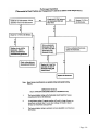
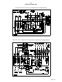
1
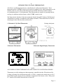
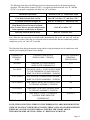
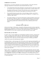
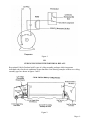
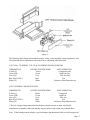
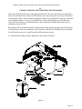
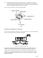
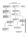
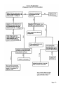
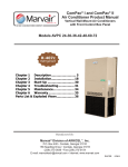
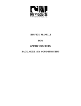
SERVICE MANUAL
12VDC WALL THERMOSTAT
AIR CONDITIONING
SYSTEMS
ROOFTOP UNITS ONLY
! WARNING - SHOCK HAZARD!
TO PREVENT THE POSSIBILITY OF SEVERE PERSONAL INJURY, DEATH, OR
EQUIPMENT DAMAGE DUE TO ELECTRICAL SHOCK, ALWAYS BE SURE THE
POWER SUPPLY TO THE APPLIANCE IS DISCONNECTED BEFORE DOING ANY
WORK ON THE APPLIANCE. THIS CAN NORMALLY BE ACCOMPLISHED BY
SWITCHING THE BREAKER FOR THE AIR CONDITIONER TO OFF,
DISCONNECTING ALL EXTERNAL ELECTRICAL CONNECTIONS AND CORDS,
SWITCHING ON BOARD ELECTRICAL GENERATORS AND INVERTERS TO OFF,
AND REMOVING THE CABLE FROM EACH POSITIVE TERMINAL ON ALL
STORAGE AND STARTING BATTERIES.
DANGER
SOME DIAGNOSTIC TESTING MAY BE DONE ON ENERGIZED CIRCUITS.
ELECTRICAL SHOCK CAN OCCUR IF NOT TESTED PROPERLY. TESTING TO BE
DONE BY QUALIFIED TECHNICIANS ONLY
The steps outlined in this manual are intended to guide the service technician through the
process of correctly diagnosing a Coleman Mach series rooftop air conditioner
with a remote wall thermostat control system.
Page -1-
TABLE OF CONTENTS
PAGE
I.
INTRODUCTION TO WALL THERMOSTATS ......................
3
II
INTRODUCTION TO RELAYS ................................................. 5
HOW DO RELAYS FUNCTION ..................................... 5
III
CHECKING CEILING PLENUMS WITH INDIVIDUAL
RELAYS ...................................................................................... 6
IV
CHECKING CEILING PLENUMS WITH PRINTED
CIRCUIT BOARDS .................................................................... 8
CHECKING THE THERMOSTAT OPERATION .......... 9
CHECKING THE PRINTED CIRCUIT BOARD
OPERATION .................................................................. 10
V
DIAGNOSTIC FLOW CHARTS ...............................................
VI
WIRING DIAGRAMS ............................................................. 16
11
Page -2-
I.
INTRODUCTION TO WALL THERMOSTATS
All of the air conditioning functions are controlled by the wall mounted thermostat . These
thermostats utilize a 12 VDC electrical circuit which is supplied by the vehicle manufacture or the
installer of the A/C unit. Most of the thermostats provided by Recreation Vehicle Products
are combination (Heat / Cool) thermostats. These thermostats are capable of operating both the
roof top air conditioner and any furnace with a 12 VDC control circuit.
The Figures below list three of the most commonly found Coleman/RV Products Wall Mounted
Thermostats for rooftop air conditioners (heat pumps excluded). These thermostats are listed in
chronological order from the oldest to the newest.
1. Mechanical / By-Metal Thermostats
2.Electronic Thermostats
Heating Anticipator
3.Electronic Digital Display Thermostats
NOTE:
ALL THREE OF THESE THERMOSTATS ARE COMPLETELY INTERCHANGEABLE.
Thermostats are really nothing more than temperature controlled switches. When the need for
Cooling or Heating exists the thermostat sends a 12VDC(+) signal to the control relays or a P.C.
board which in turn energizes the air conditioner components or the furnace. (Note: Relays and
P.C. boards will be further discussed later in lesson II).
Page -3-
The following chart shows the different electrical connections made by the thermostat during
operation. The chart below assumes12VDC(+) is supplied to thermostat Red wire “R” and that
12VDC(-) or ground is supplied to the Blue wire “B” at all times.
Thermostat Operations
Internal 12VDC(+) Connections Made
Cool Mode Selected On Low Fan
Red “R” to Yellow “Y” and Gray “GL”
Cool Mode Selected On High Fan
Red “R” to Yellow “Y” and Green “GH”
Heat Mode Selected On Any Fan Speed
(Note: Furnace blower operates independently
from sequencer or time delay in furnace)
Red “R” to White “W”
Fan Only Selected (Hi-Fan Only)
Red “R” to Green “GH”
Note: When the auto cool mode is selected on the thermostat the fan cycles “on” and “off” with the
compressor as needed. When the on cool mode has been selected the fan runs continuously and the
compressor cycles “on” and “off” as needed.
The following chart depicts thermostat wiring and the wiring destinations for air conditioners with
control boxes containing Printed Circuit Boards.
THERMOSTAT
TERMINAL /
WIRE
CONTROL AND SUPPLY
WIRING (OEM / VENDOR)
CEILING ASSEMBLY
TERMINAL
DESIGNATION
R or RED
ONE RED, (+) 12VDC SUPPLY
WIRE TO THE THERMOSTAT
N /A
B or BLUE
TWO BLUE, ONE (-) 12VDC SUPPLY WIRE
TO THE THERMOSTAT AND ONE BLUE
WIRE TO CEILING ASSEMBLY / PLENUM
B
Y or YELLOW
ONE YELLOW, COMPRESSOR CONTROL
WIRE TO CEILING ASSEMBLY / PLENUM
Y
GH or GREEN
ONE GREEN, HIGH FAN CONTROL WIRE
TO CEILING ASSEMBLY / PLENUM
GH
GL or GRAY
ONE GRAY, LOW FAN CONTROL WIRE
TO CEILING ASSEMBLY / PLENUM
GL
W or WHITE
ONE WHITE, 12VDC (+) FURNACE
CONTROL WIRE FROM THE
THERMOSTAT
NOTE: The (W) White wire is not available on COOL ONLY thermostats.
FURNACE
NOTE: THE CONNECTING WIRES TO THE THERMOSTAT ARE PROVIDED BY THE
VEHICLE MANUFACTURER OR INSTALLER. THESE O.E.M. OR VENDOR SUPPLIED
WIRES MAY NOT BE COLOR CODED AS NOTED IN THE CHART ABOVE.
THE GROUND WIRE MUST BE A ZERO “0" RESISTANCE GROUND.
Page -4-
THERMOSTAT LOCATION
Thermostats are very sensitive instruments. For accurate temperature control and comfort the
following considerations for thermostat locations should be taken into account:
1.
Locate the thermostat on an inside wall about five foot above the floor. Pick a dry area where
air circulation is good. The thermostat should be mounted within a reasonable distance from
the appliance the thermostat will control. This will assure a more accurate temperature
relationship between the thermostat and the appliance the thermostat will control.
2.
Do not install the thermostat where there are unusual heating conditions; such as direct
sunlight, heat producing appliances (television, radio, wall lamp, etc.); or a furnace or air
conditioner supply register.
3.
Note: When installing or servicing these thermostats the technician should take all necessary
precautions not to short any positive wire to ground. Permanent damage to the thermostat
may occur. Make sure all connections are good and tight. Loose connections may cause
relay chattering which leads to welded relay contacts on air conditioner printed circuit
boards.
II.
INTRODUCTION TO RELAYS
In the previous chapter on thermostats we learned the wall thermostat makes necessary connections
that provide low voltage power to initiate all of the air conditioning or heating functions. There is one
question left unanswered. How do we use this 12VDC power to operate a 115VAC appliance?
THE ANSWER IS: We use relays or printed circuit boards with relays located on them.
HOW DO RELAYS FUNCTION
So what is a relay? A relay is defined as an electromagnetic mechanism moved by a small electrical
current in a control circuit (12VDC in this case). How does this relay work? As this mechanism
moves back and forth in the relay it will open or close a set of contacts capable of carrying high
voltage and (115VAC in this case). All of our control circuit relays are normally open and the
contacts close as power from the thermostat is applied.
As shown in Figure 1. on the next page, the 115VAC power to the compressor is interrupted by a set
of normally open contacts on the relay. In order for these contacts to close 12VDC must be applied
by the wall thermostat to the relay coil. When the thermostat switch is placed in the cool position
12VDC(+) travels from the thermostat red wire to the thermostat yellow (Y) wire and then to the
relay coil. When the coil is activated an electromagnet inside the relay will pull the contacts closed.
The 115VAC will now operate the compressor until the thermostat opens or the system switch is
turned to the off position.
Figure 1. shows a very simplified control circuit for compressor operation only. The entire control
circuit for the A/C / Heating system would include the rest of the thermostat functions and possibly 2
or 3 more relays. In addition to the compressor relay you would need a separate relay for Low Fan,
one for High Fan, and possibly one for Heat, if a heat pump or electric heating element is used.
Please refer to the previous lesson or use the chart below for proper wiring from the wall thermostat
to each individual relay.
Page -5-
Figure 1
III.
CEILING PLENUMS WITH INDIVIDUAL RELAYS
Recreational Vehicle Products built 2 types of ceiling assembly packages which incorporate
individual relays for the air conditioner system functions. Line drawing examples of these two ceiling
assembly types are shown in figures 2 and 3.
Figure 2.
Page -6-
Figure 3
The following charts depict the thermostat control wiring, ceiling assembly wiring destinations, and
relay functions for air conditioners with control boxes containing individual relays
6799-720 & -726 SERIES, 7330-720 & 726 SERIES CEILING PLENUMS
THERMOSTAT
Yellow (Y)
Green (GH)
Gray (GL)
Blue (B) (12VDC-)
White (W)
CEILING PLENUM WIRE*
Yellow
Green
Gray
Blue
White
UNIT OPERATION
Compressor relay
High Fan relay
Low Fan relay
N/A
Furnace or Heat Element relay
6799-730 SERIES CEILING PLENUM
THERMOSTAT
CEILING PLENUM WIRE*
UNIT OPERATION
Yellow (Y)
Black
Compressor
Green (GH)
Green
High Fan
Gray (GL)
Gray
Low Fan
Blue (B) (12VDC-)
Blue
N/A
White (W)
White
Furnace or Heat Element relay
.
* The low voltage wiring connections for the these control systems are hard wired by the
manufacturer or installer of the unit and they may not all use color coded wire as noted above.
Note: If the heating system includes a gas fired furnace the thermostat white wire will energize the
Page -7-
furnace control circuit, (Usually a time delay relay located at the furnace).
IV.
CEILING PLENUMS WITH PRINTED CIRCUIT BOARDS
Most of the 7000 and 8000 series ceiling plenums built since 1992 have had Printed Circuit Boards
instead of individual relays. Printed circuit boards are less costly and require less wiring. The Printed
Circuit Boards all have relays mounted permanently on them. Even though the boards may look much
more complicated they are very easy to troubleshoot. On the following pages you will find some
visual aids that will help you trouble shoot these units without removing the thermostat or the air
conditioner control box lid.
Recreational Vehicle Products has and is building many ceiling assembly packages which use Printed
Circuit Boards to control air conditioner system functions. Just like the individual relays, the Printed
Circuit Board must receive a signal from the wall thermostat to operate.
A common ducted ceiling assembly application is shown here in Figure 4.
Figure 4
Page -8-
Note: In ducted applications similar to the one found in Figure 4, the Printed Circuit Board /
Control Box Assembly is found mounted in the return air opening of the Air Conditioner. In
some older applications the Printed Circuit Board / Control Box Assembly will be located in
the center of the roof opening just above the return air grille.
Figure 5 shows an exploded view of the Control Box Assembly
Figure 5
CHECKING THE THERMOSTAT OPERATION
The 12 Volt DC signal from the wall thermostat may be checked at the Low Voltage Terminal Strip
(Figure 6) located externally on the ceiling plenum wiring box
Figure 6. Low Voltage Terminal Strip
Anytime the thermostat is placed in the FAN ONLY position you should be able to read
12VDC between terminals GH and B at the Low Voltage Terminal Strip (see figure 6) .
Anytime the thermostat is placed in the LOW COOL position you should be able to read
12VDC between terminals GL and B for the Low Fan, and between terminals Y and B for
compressor operation.
Page -9-
Anytime the thermostat is placed in the HIGH COOL position you should be able to read
12VDC between terminals GH and B for the High Fan, and between terminals Y and B for
Compressor operation.
Note: Thermostat operation in the Heating Mode cannot be tested at the Ceiling Assembly Low
Voltage Terminal Strip if the thermostat is operating a gas fired furnace.
Note: The wall thermostat will be equipped with an optional Electric Heat / Gas Heat switch if the
Recreational Vehicle is equipped with a Heat Pump or with an Electric Heating Element. In
this case the Electric Heat Mode may be checked the Low Voltage Terminal Strip. In either
case the Low Voltage Terminal Strip will have an additional terminal labeled “W” for electric
heating operation. When Electric Heat is chosen at the thermostat you should be able to read
12VDC between terminals W and B. Please note, the “W” terminal is not shown on the Low
Voltage Terminal Strip (Figure 6) or in the chart below because it is not tremendously
common.
.
THERMOSTAT
CEILING ASSEMBLY TERMINAL
UNIT OPERATION
Yellow (Y)
(Y)
Compressor
Green (GH)
(GH)
High Fan
Gray (GL)
(GL)
Low Fan
Blue (B) (12VDC-)
(B)
N/A
If you do not find voltage at the Ceiling Assembly Low Voltage Terminal Strip as described above
the problem needs to be traced back to the thermostat or the vehicles low voltage wiring.
CHECKING THE PRINTED CIRCUIT BOARD OPERATION
Low voltage MUST be verified at the Low Voltage Terminal Strip as described earlier in this text or
as noted in the chart below before preceding to the next step, or checking the Printed Circuit Board.
In order to continue you must first verify the 115VAC power source to the Air Conditioner Control
Box Assembly. If the 115VAC power source is NOT present, all of the Air Conditioner functions will
be dead and power must be restored to continue. 115VAC power must be present to the Circuit
Board if any one of the Air Conditioner functions are working.
The operation of the printed circuit board may be checked at the High Voltage 9-Pin Connector
(Figure 7) without removing the electric box lid. The chart below shows the 115VAC connections
made by the Circuit Board to the High Voltage 9-Pin Connector
THERMOSTAT CONNECTIONS
AT THE LOW VOLTAGE
TERMINAL STRIP
12VDC at Y and B
12VDC at GH and B
12VDC at GL and B
115VAC CONNECTIONS
MADE BETWEEN TERMINALS
AT THE 9 PIN CONNECTOR
Terminals # 1 and # 3
Terminals # 5 and # 9
Terminals # 6 and # 9
Page -10-
Figure 7. High Voltage 9-Pin Connector
Note: To check voltage at the 9 pin connector plug it may be necessary to unplug the upper unit from
the control box
If the Air Conditioner is still not functioning and both 12VDC and 115VAC are present and
accountable at their proper locations the problem is located in the upper unit.
If the correct 115VAC connections are NOT made at the 9 pin connector plug after12VDC power
is applied to the Low Voltage Terminal Strip; the problem is in the Printed Circuit Board with
one exception as described below.
The low temperature freeze thermistor could open the compressor relay on the Circuit Board if the Air
Conditioner Evaporator Coil starts to freeze. If this switch is opens you would still have 12VDC at
terminals Y and B, but no voltage would be present at terminals 1 and 3 in the High Voltage 9-Pin
Connector. The Freeze Thermister opens if the evaporator coil temperature drops below 32 degrees and
closes at 55 degrees. The probe end of this switch should be found pushed into the fins of the evaporator
coil and the wires are hooked to the Printed Circuit Board. It is OK to remove the thermister wire from
the Board and jump around these terminals fore diagnostic purposes.
If the Air Conditioner compressor is running and NO VOLTAGE is found between terminals Y
and B on the Low Voltage Terminal Strip the Printed Circuit Board must be replaced. The
compressor relay has evidently welded shut.
In conclusion, you can save a lot of time if you get in the habit of going immediately to the ducted control
box assembly for trouble shooting purposes. There in a matter of minutes you can tell if the problem is
in the Thermostat, the Printed Circuit Board, or the Upper Unit.
V.
DIAGNOSTIC FLOW CHARTS
Note: When working with the following diagnostic flow charts, start at the top left corner and work
towards the right or down the page as applicable. Do not skip around or start in middle without
performing all prior steps.
DANGER
THE FOLLOWING DIAGNOSTIC TESTING WILL BE DONE ON ENERGIZED
CIRCUITS. ELECTRICAL SHOCK CAN OCCUR IF NOT TESTED PROPERLY.
TESTING TO BE DONE BY QUALIFIED TECHNICIANS ONLY
Page -11-
Page -12-
Page -13-
Page -14-
Page -15-
VI.
WIRING DIAGRAMS
7330-730 & 8330-733 Series Cool Only Ducted Ceiling Plenums
7330-735, 7330-736 & 8330-735 Series Heat/ Cool Ducted Ceiling Plenums
Page -16-
7330-720 & 8330-723 Series Cool Only Remote Free Delivery Ceiling Plenums
7330-725, 7330-726 & 8330-725 Series Heat/Cool Remote Free Delivery Ceiling Plenums
Page -17-
RV Products
A Division of Airxcel, Inc.
P.O. Box 4020
Wichita, KS 67204
1976-376 (4-02)
Page -18-