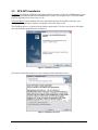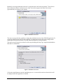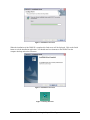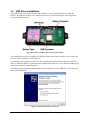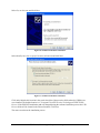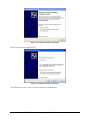
1
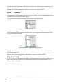
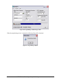
GPS-207S PROGRAMMING SOFTWARE
USER MANUAL
CES WIRELESS TECHNOLOGIES, CORP.
925-122 South Semoran Boulevard
Winter Park, Florida 32792
September 14, 2010
GPS207S Programming Software Manual vAp1.doc
Revision A.1
© Copyright CES WIRELESS TECHNOLOGIES CORP. (2010)
The information contained in this document is subject to change without notice and should not be construed as a commitment by CES
WIRELESS TECHNOLOGIES CORP. unless such commitment is expressly given in a covering document.
TABLE OF CONTENTS
TABLE OF CONTENTS ..............................................................................................................................2
TABLE OF FIGURES ..................................................................................................................................3
COPYRIGHT ................................................................................................................................................4
CHANGE LOG .............................................................................................................................................4
1.0
Introduction....................................................................................................................................5
2.0
GPS-207S Installation....................................................................................................................6
3.0
USB Drivers Installation................................................................................................................9
4.0
Using the GPS207S .....................................................................................................................17
4.1
Configure the Com Port ...............................................................................................................17
4.1.1
Determining the Com Port Number...................................................................................17
4.1.2
Configuring the Com Port in the GPS207S.......................................................................19
4.2
File Menu.....................................................................................................................................20
4.2.1
Open ..................................................................................................................................21
4.2.2
Save ...................................................................................................................................21
4.2.3
Save As ..............................................................................................................................21
4.2.4
Exit ....................................................................................................................................22
4.3
Configure Menu...........................................................................................................................22
4.3.1
Com Port............................................................................................................................23
4.3.2
Verify Connected...............................................................................................................23
4.3.3
Connect New Device .........................................................................................................23
4.4
Help Menu ...................................................................................................................................23
4.4.1
About .................................................................................................................................24
4.5
GPS207S Main Form...................................................................................................................24
4.5.1
Cellular System Parameters...............................................................................................25
4.5.2
Communication Parameters...............................................................................................25
4.5.2.1 Unit Number ......................................................................................................................26
4.5.2.2 IP Address..........................................................................................................................26
4.5.2.3
Port ...................................................................................................................................26
4.5.3
GPS Configuration ............................................................................................................26
4.5.3.1
GPS Reporting Type.........................................................................................................26
4.5.3.2 Stationary Interval .............................................................................................................26
4.5.3.3 In Motion Interval..............................................................................................................26
4.5.3.5 Static Asset ........................................................................................................................26
4.5.3.5 In Motion ...........................................................................................................................27
4.5.4
Send Config ............................................................................................................................27
6.0
Support.........................................................................................................................................29
© CES Wireless Technologies Corp – 2010
Page 2 of 29
TABLE OF FIGURES
Figure 1: Installation Screen #1.....................................................................................................................6
Figure 2: Installation Screen #2.....................................................................................................................6
Figure 3: Installation Screen #3.....................................................................................................................7
Figure 4: Installation Screen #4.....................................................................................................................7
Figure 5: Installation Screen #5.....................................................................................................................8
Figure 6: Installation Screen #6.....................................................................................................................8
Figure 7: Desktop Shortcut ...........................................................................................................................8
Figure 8: Location of USB Connector inside of the GPS207 .......................................................................9
Figure 9: Found New Hardware Wizard #1 ..................................................................................................9
Figure 10: Found New Hardware Wizard #2 ..............................................................................................10
Figure 11: Found New Hardware Wizard #3 ..............................................................................................10
Figure 12: Found New Hardware Wizard #4 ..............................................................................................11
Figure 13: Found New Hardware Wizard #5 ..............................................................................................11
Figure 14: Found New Hardware Wizard #6 ..............................................................................................12
Figure 15: Found New Hardware Wizard #7 ..............................................................................................12
Figure 16: Found New Hardware Wizard #8 ..............................................................................................13
Figure 17: Hardware Wizard, Windows Compatibility Test.......................................................................13
Figure 18: Found New Hardware Wizard #9 ..............................................................................................14
Figure 19: Found New Hardware Wizard #10 ............................................................................................14
Figure 20: Found New Hardware Wizard #11 ............................................................................................15
Figure 21: Found New Hardware Wizard #12 ............................................................................................15
Figure 22: Hardware Wizard, Windows Compatibility Test.......................................................................16
Figure 23: Found New Hardware Wizard #13 ............................................................................................16
Figure 24: GPS207S Main Form.................................................................................................................17
Figure 25: System Properties ......................................................................................................................18
Figure 26: System Properties, Hardware.....................................................................................................18
Figure 27: Device Manager.........................................................................................................................19
Figure 28: Expand the Ports in the Device Manager...................................................................................19
Figure 29: Ports (COM & LPT) in the Device Manager.............................................................................19
Figure 30: Configure Menu.........................................................................................................................20
Figure 31: Select Com Port Form................................................................................................................20
Figure 32: File Menu...................................................................................................................................20
Figure 33: Open Dialog...............................................................................................................................21
Figure 34: GPS207S Title Bar Displaying Configuration File Name .........................................................21
Figure 35: Save GPS207 Config File ..........................................................................................................22
Figure 36: Save Current Configuration Dialog ...........................................................................................22
Figure 37: Configure Menu.........................................................................................................................23
Figure 38: Device is Connected Dialog ......................................................................................................23
Figure 39: Device Not Connected or Com Port Not Properly Defined Dialog...........................................23
Figure 40: Help About Form .......................................................................................................................24
Figure 41: GPS207S Main Form.................................................................................................................25
Figure 42: Select Network...........................................................................................................................25
Figure 43: Static Asset - Stationary Interval Selections..............................................................................26
Figure 44: In Motion - Stationary Interval Selections.................................................................................27
Figure 45: In Motion - In Motion Interval Selections .................................................................................27
© CES Wireless Technologies Corp – 2010
Page 3 of 29
COPYRIGHT
The information in this manual and any software in this product remain the property of CES Wireless
Technologies Corp. Duplication or disclosure is not permitted without the prior written consent of CES
Wireless. CES Wireless reserves the right to change products, specifications, and installation data at any
time, without notice. All information contained in this document is carefully prepared and offered in good
faith as a guide in the installation, operation, use and servicing of our products. Installers must insure that
the final installation operates satisfactory, within relevant regulatory requirements. We accept no
responsibility for incorrect installations.
Windows XP and 2000 are registered trademarks of Microsoft. All other trademarks are the property their
respective owners.
A CES Wireless publication. © Copyright CES Wireless 1997-2010
CHANGE LOG
Date
2010-08-27
Author
Doug Hamilton
2010-09-14
Doug Hamilton
Description
Initial release (A.0)
Added new images for the Static Interval after once or twice a week
reporting capability was added.
© CES Wireless Technologies Corp – 2010
Page 4 of 29
1.0
Introduction
The GPS-207S Programming Software is used to program the GPS-207 asset tracking device. This
manual describes the installation of the software and the USB drivers required to communicate with the
device. It also describes the options available within the software and how they effect the operation of the
GPS-207 including what effects different settings have on the estimated life of the battery.
Supported operating systems for the GPS207S include Windows 2000, Windows XP and Windows Vista.
© CES Wireless Technologies Corp – 2010
Page 5 of 29
2.0
GPS-207S Installation
CD Install: To install the GPS207S programming software insert the CD into the CD-ROM drive of your
computer. The installation should start automatically. If it does not, navigate to the CD using Windows
Explorer and double click on the setup.exe file.
Download Install: If the installation files were downloaded navigate to the folder where they were
downloaded, using Windows Explorer, and double click on the setup.exe file.
The installation process is typical for most Windows applications. The first screen (below) will appear
once the installation program has been initialized.
Figure 1: Installation Screen #1
Click on the Next button to advance to the second part of the installation process.
Figure 2: Installation Screen #2
© CES Wireless Technologies Corp – 2010
Page 6 of 29
Read the License Agreement and select the “I accept the terms in the license agreement”. Then click on
the next button to advance to the next screen. Note: If you do not agree to the terms if the license
agreement then you cannot use the software.
Figure 3: Installation Screen #3
The next screen provides the capability to change the installation location of the GPS207S application. To
accept the default location click on the next button. To change the location click on the Change button
and navigate to the desired location. Click OK when done and click on the next button
The next screen will show the user details of the setup including the Setup Type, Application Installation
Path and User information.
Figure 4: Installation Screen #4
Click on the install button to start the installation process. A screen similar to the one shown below will
be displayed while the application is installed.
© CES Wireless Technologies Corp – 2010
Page 7 of 29
Figure 5: Installation Screen #5
When the installation of the GPS207S is complete this final screen will be displayed. Click on the finish
button to exit the installation application. You should now have shortcuts to the GPS207S on the
computer desktop and on the start menu.
Figure 6: Installation Screen #6
Figure 7: Desktop Shortcut
© CES Wireless Technologies Corp – 2010
Page 8 of 29
3.0
USB Drivers Installation
The GPS207S has a mini-USB style connector inside that is used to program the device. Open the
GPS207. Disconnect the battery if it is connected and remove it from the enclosure. This will provide
access to the USB connector.
Figure 8: Location of USB Connector inside of the GPS207
The communication process is handled via USB Drivers that create virtual com ports. These virtual com
ports are used to communicate with the device.
To install the drivers connect the GPS-207 to the computer using a mini-USB to USB cable (CES P/N
CBLxx). When the GPS207 is connected to the computer for the first time, or to a different USB port, the
user will be prompted to install the drivers.
The Windows operating system automatically detects the presence of a new USB device. The following
screen will be displayed:
Figure 9: Found New Hardware Wizard #1
© CES Wireless Technologies Corp – 2010
Page 9 of 29
Select No, not this time and click Next.
Figure 10: Found New Hardware Wizard #2
Select Install from a list or specific location (Advanced) and click Next.
Figure 11: Found New Hardware Wizard #3
Click on the Include this location in the search check box. Browse to the folder where the USB drivers
were installed. The default location is C:\Program Files\CES Wireless Technologies\GPS207S\USB
Drivers. If the GPS207S installation path was changed during the software installation process the USB
Drivers folder will be located in the selected location. Click Next.
The next screen shows the installation process.
© CES Wireless Technologies Corp – 2010
Page 10 of 29
Figure 12: Found New Hardware Wizard #4
Once the installation of the driver for the Locosto USB device is complete the following screen will be
displayed:
Figure 13: Found New Hardware Wizard #5
Click Finish and the next step in the USB device installation process will begin and the following screen
will be displayed.
© CES Wireless Technologies Corp – 2010
Page 11 of 29
Figure 14: Found New Hardware Wizard #6
Select No, not this time and click Next.
Figure 15: Found New Hardware Wizard #7
Select Install from a list or specific location (Advanced) and click Next.
© CES Wireless Technologies Corp – 2010
Page 12 of 29
Figure 16: Found New Hardware Wizard #8
Click on the Include this location in the search check box. Browse to the folder where the USB drivers
were installed. The default location is C:\Program Files\CES Wireless Technologies\GPS207S\USB
Drivers. If the GPS207S installation path was changed during the software installation process the USB
Drivers folder will be located in the selected location. Click Next.
The following screen may be displayed.
Figure 17: Hardware Wizard, Windows Compatibility Test
If the above is displayed click on Continue Anyway and the software will be installed. The following
screen will be displayed.
© CES Wireless Technologies Corp – 2010
Page 13 of 29
Figure 18: Found New Hardware Wizard #9
Click Finish and the next step in the USB device installation process will begin and the following screen
will be displayed.
Figure 19: Found New Hardware Wizard #10
Select No, not this time and click Next.
© CES Wireless Technologies Corp – 2010
Page 14 of 29
Figure 20: Found New Hardware Wizard #11
Select Install from a list or specific location (Advanced) and click Next.
Figure 21: Found New Hardware Wizard #12
Click on the Include this location in the search check box. Browse to the folder where the USB drivers
were installed. The default location is C:\Program Files\CES Wireless Technologies\GPS207S\USB
Drivers. If the GPS207S installation path was changed during the software installation process the USB
Drivers folder will be located in the selected location. Click Next.
The following screen may be displayed.
© CES Wireless Technologies Corp – 2010
Page 15 of 29
Figure 22: Hardware Wizard, Windows Compatibility Test
If the above is displayed click on Continue Anyway and the software will be installed. The following
screen will be displayed.
Figure 23: Found New Hardware Wizard #13
Click Finish to complete the installation of the USB drivers.
© CES Wireless Technologies Corp – 2010
Page 16 of 29
4.0
Using the GPS207S
To run the GPS207S programming software double click on the icon on the desktop or click on the Start
button, select All Programs, select the CES Wireless Technologies folder and then click on GPS207S.
The main form will be displayed.
Figure 24: GPS207S Main Form
4.1
Configure the Com Port
The first step in using the GPS207S is to configure the com port used to communicate with the GPS207.
4.1.1 Determining the Com Port Number
With the GPS207 connected to a USB port bring up the Windows Device Manager to determine what
com port has been assigned to the GPS207. To access the Device Manager click ob the Start button and
select Control Panel. Once the Control Panel is displayed select System.
© CES Wireless Technologies Corp – 2010
Page 17 of 29
Figure 25: System Properties
Click on the Hardware tab. Click on the button labeled Device Manager.
Figure 26: System Properties, Hardware
The Device Manager will now be displayed.
© CES Wireless Technologies Corp – 2010
Page 18 of 29
Figure 27: Device Manager
Click on the plus sign in front of Ports (COM & LPT).
Figure 28: Expand the Ports in the Device Manager
Something similar to the image below will be displayed.
Figure 29: Ports (COM & LPT) in the Device Manager
Make a note of the com port assigned to the CES Wireless Technologies GPS207 Modem. In the example
above this is COM6. This is the com port to use to program with the GPS207.
4.1.2 Configuring the Com Port in the GPS207S
To configure the com port select Configure on the main menu and then select Com Port. The Select Com
Port form will be displayed.
© CES Wireless Technologies Corp – 2010
Page 19 of 29
Figure 30: Configure Menu
Figure 31: Select Com Port Form
Select the Com Port number that has been assigned to the GPS207 Modem as noted in section 4.1.1. Click
OK. The selection will be stored in the application settings so that this only needs to be done once, or if
the Com Port number changes (i.e. if the GPS207 is connected to a different USB port).
The GPS207S is now configured to communicate with the GPS207.
4.2
File Menu
The File menu has four options on it. They are Open, Save, Save As and Exit.
Figure 32: File Menu
© CES Wireless Technologies Corp – 2010
Page 20 of 29
4.2.1 Open
The Open menu selection provides the capability to open a saved configuration. To open a saved
configuration select Open on the File menu. The Open dialog will be displayed.
Figure 33: Open Dialog
Select the desired save configuration file (GPS207S configuration files have a .207 extension) and click
Open. The file name of the configuration that was opened will be displayed in the GPS207S title bar.
Figure 34: GPS207S Title Bar Displaying Configuration File Name
4.2.2 Save
To save the current configuration select Save. If a configuration file was previously loaded or the current
configuration was previously saved the current settings will be saved in the same file. Otherwise the Save
As dialog will be displayed (refer to Section 4.2.3).
4.2.3 Save As
To save the current configuration in a new file select Save As. The Save GPS207 Config File form will be
displayed.
© CES Wireless Technologies Corp – 2010
Page 21 of 29
Figure 35: Save GPS207 Config File
This is the typical Windows save file dialog. Navigate to the folder where you wish to save the file. Enter
the file name and click on Save. The GPS207 configuration file extension (.207) will automatically be
appended onto the file name that was entered.
4.2.4 Exit
To exit the GPS207S application select File and then Exit. A prompt will be displayed to save the current
configuration. It is highly recommended that the configuration be saved the first time the application is
configured. Otherwise the Com Port will have to be configured again next time the application is used.
Figure 36: Save Current Configuration Dialog
Note – the GPS207S application can also be closed by clicking on the Exit button or the red X in the
upper right corner of the main application form.
4.3
Configure Menu
The Configure menu has three items on it. They are Com Port, Verify Connected and Connect New
Device.
© CES Wireless Technologies Corp – 2010
Page 22 of 29
Figure 37: Configure Menu
4.3.1 Com Port
Refer to Section 4.1 for more information on how to configure the com port.
4.3.2 Verify Connected
To verify that a device is connected and that the com port has been properly configured select Verify
Connected.
If a device is connected and the com port has been properly configured the following dialog will be
displayed.
Figure 38: Device is Connected Dialog
If a device is not connected or the com port has not been properly configured the following dialog will be
displayed.
Figure 39: Device Not Connected or Com Port Not Properly Defined Dialog
4.3.3 Connect New Device
To connect a new device select the Connect New Device menu selection. This is important to do when
programming multiple devices. Select this item and then disconnect the current device. Connect the new
device.
4.4
Help Menu
There is one option on the Help menu: About.
© CES Wireless Technologies Corp – 2010
Page 23 of 29
4.4.1 About
Selecting About on the Help menu will cause the following form to be displayed. The form displays the
copyright notice and the version number of the software as well as other important information.
Figure 40: Help About Form
Click OK to close the form.
4.5
GPS207S Main Form
The main form of the GPS207S has three categories of programming parameters, a button to send the
configuration to the GPS207, a progress bar, a label displaying the estimated battery life based upon the
currently selected parameters and an exit button.
The different categories of programming parameters are
Cellular System Parameters
Communication Parameters
GPS Configuration
© CES Wireless Technologies Corp – 2010
Page 24 of 29
Figure 41: GPS207S Main Form
4.5.1 Cellular System Parameters
The Cellular System Parameters contain the information necessary to connect to the cellular network.
These values are supplied by the cellular provider. The parameters are APN, User Name and Password.
Enter the information that was provided by the cellular provider. Known cellular parameters can be
selected by clicking on the button next to the APN field. When this is done the Select Network form will
be displayed.
Figure 42: Select Network
If using one of the networks on the form click on it and click OK. This will cause the cellular parameters
in the GPS207S main form to be updated with these values. If the network being used is not in the list you
will have to contact the cellular provider to obtain them.
4.5.2 Communication Parameters
The Communication Parameters contain the information required to send data to Power-Trak3 or to
FleetLinc. There are three fields: Unit Number, IP Address and Port.
© CES Wireless Technologies Corp – 2010
Page 25 of 29
4.5.2.1
Unit Number
The Unit Number is a unique identifier that enables the software to determine which device is which. It is
very important that a unique number be programmed into each GPS-201. If using FleetLinc the Unit
Number will be provided by CES Wireless Technologies.
4.5.2.2
IP Address
The IP Address of the software (i.e. Power-Trak3 or FleetLinc) should be entered here. This is the IP
Address to which the GPS-207 will send packets to.
4.5.2.3
Port
The Port number used to communicate with the server should be entered here. This port should match the
configuration of the software on the server.
4.5.3 GPS Configuration
There are also three fields in the GPS Configuration. They are GPS Reporting Type, Stationary Interval
and In Motion Interval.
4.5.3.1
GPS Reporting Type
There are two selections for the GPS Reporting Type. They are Static Asset (refer to Section 4.5.3.4) and
In Motion (refer to Section 4.5.3.5).
4.5.3.2
Stationary Interval
The Stationary Interval is the interval the device should report at. For a Static Asset this is how often the
device should report its position. For an In Motion asset this is the interval that the GPS207 should report
its position when not moving.
4.5.3.3
In Motion Interval
The In Motion Interval only applies when the GPS Reporting Type is set to In Motion. This is the interval
at which the GPS207 will report while it is moving.
4.5.3.5
Static Asset
If the GPS207 is to be programmed to report its position at fixed time intervals regardless of movement
select Static Asset as the GPS Reporting Type.
The next step is to select the desired reporting interval from the available selections. The minimum value
is 120 minutes (2 hours) and the maximum is 10080 minutes (once per week).
Figure 43: Static Asset - Stationary Interval Selections
© CES Wireless Technologies Corp – 2010
Page 26 of 29
Note: the label at the bottom of the GPS207S form will display the estimated battery life based upon the
selected reporting interval.
Once the report interval is defined the configuration is ready to be sent to the GPS207.
4.5.3.5
In Motion
If the GPS207 is to be programmed to report using the In Motion GPS Reporting Type (report position at
one interval while stationary and at another interval if it is in motion) there are two additional parameters
– the stationary interval and the in motion interval.
The Stationary Interval has the following selections when using the In Motion type.
Figure 44: In Motion - Stationary Interval Selections
After selecting the stationary reporting interval the next step is to select the In Motion reporting interval.
These are the available selections
Figure 45: In Motion - In Motion Interval Selections
Note: the label at the bottom of the GPS207S form will display the estimated battery life based upon the
selected reporting intervals.
Once the report intervals are defined the configuration is ready to be sent to the GPS207.
4.5.4 Send Config
Once all of the parameters are defined the GPS207 can be programmed. This is done by clicking on the
Send Config button. As the GPS207 is programmed the progress bar to the right of the Send Config
button will display the progress.
© CES Wireless Technologies Corp – 2010
Page 27 of 29
Figure 46: Programming a GPS207 Progress Bar
When the programming process is complete the following dialog will be displayed
Figure 47: Programming Complete
© CES Wireless Technologies Corp – 2010
Page 28 of 29
6.0
Support
If you need help, we are easily accessible ….
Telephone:
Call 407-679-9440, and ask for product support.
Fax:
407-679-8110
Email:
[email protected]
Skype:
Please email [email protected] to obtain your currently assigned support
engineer’s Skype address.
Product support may ask you to E-MAIL a copy of the programmed parameters to us for analysis. To do
this, go to FILE on the DP-1000S main menu, and click on SAVE AS. Note the path to the saved file in
the save file dialog. Attach this file to an e-mail and send it to you product support representative or to the
e-mail address noted above.
Product support may ask you to PRINT a copy of the programmed parameters, and fax to for analysis. To
do this, go to FILE on the DP-1000S main menu, and click on PRINT.
Support Resources: www.ceswireless.com
FTP Site: Please go to www.ceswireless.com and register for an FTP site User Name and Password
© CES Wireless Technologies Corp – 2010
Page 29 of 29