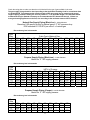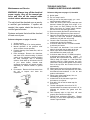
1
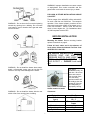
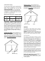
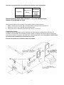
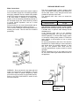
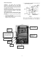
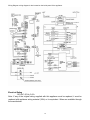
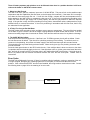
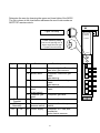
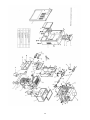
AUTOMATIC
INSTANTANEOUS WATER HEATER
Controlled Energy Corp.
340 Mad River Park
Waitsfield, VT 05673
Tel. (800) 642-3111
Tech support is available at
www.controlledenergy.com
INSTALLATION AND OWNER’S
MANUAL
FOR YOUR SAFETY - This product
must be installed and serviced by a
professional
service
technician,
qualified in water heater installation.
Installation and/or operation could
create carbon monoxide gas and flue
gases, which could cause serious injury
or death. Improper installation and/or
operation will void the warranty.
In
the
Commonwealth
of
Massachusetts this product must be
installed by a licensed plumber.
WARNING: If the information in this
manual is not followed exactly, a fire or
explosion may result, causing property
damage, personal injury or death.
MODEL AQUASTAR 240 FX
•
Do not store or use gasoline or
other flammable vapors and liquids
in the vicinity of this or any other
appliance.
•
WHAT TO DO IF YOU SMELL GAS
•
Suitable for water (potable) heating only
WATER HEATER
•
Manufactured by Takagi Industrial Co. USA Inc.
The Aquastar name is trademarked and licensed by Bosch.
•
•
•
•
•
•
•
•
•
•
FEATURES
ENDLESS HOT WATER
ON DEMAND, NO STAND-BY LOSS
COMPACT, SAVE SPACE
CONSERVES ENERGY
COMPUTER CONTROLS
COMPUTERIZED SAFETY
NO PILOT LIGHT
•
•
AVAILABLE ACCESSORIES (see p.16)
REMOTE THERMOSTAT –240TSTAT
WALL SUPPORT BRACKETS – 240BRACKET
HORIZONTAL VENT TERMINATOR WITH
DRAFT DAMPER - FXHOOD
•
1
Do not try to light any
appliances.
Do not touch any electrical
switch, also do not use any
phone in your building.
Immediately call your gas
supplier from a neighbor’s
phone. Follow the gas
supplier’s instructions.
If you cannot reach your gas
supplier,
call
the
fire
department.
Installation and service must be
performed by a qualified installer,
service agency or the gas supplier.
SPECIFICATIONS
TABLE OF CONTENTS
For Your Safety
…………. 3
Operation
…………. 4
•
•
•
•
•
•
General
Normal Operation
Start Up
Temperature
Freeze Prevention
Winterizing
Installation
•
•
•
•
•
•
•
•
•
•
•
•
…………. 4
…………. 4
…………. 4
…….4 & 22
..….……. 4
…………. 5
Natural Gas Input
Min. 37,000 Btu
Max. 165,000 Btu
LP Gas Input
Min. 35,000 Btu
Max. 165,000 Btu
Gas Connection
¾” NPT
Water Connections
¾” NPT
Water Pressure
Min. 15 psi
Max. 150 psi
…………. 5
Natural Gas Pressure
before appliance:
General
…………. 5
Outdoor Installation
…………. 6
Indoor Installation
…………. 7
High Altitude
…….…… 7
Combustion Air
……….….8
Venting
……….….8
Manufactured Home (Mobile home) and
Recreation Park Trailer Installation
…………..10
Gas Supply
…………. 10
Water Connections
…………. 12
Pressure Relief Valve …………. 12
Electrical Connection …………. 13
Wiring Diagram
…………. 14
Initiating the Heater
…………. 15
Accessories
…………..16
LP Gas Pressure
before appliance:
…………. 17
Common Questions
…………. 17
Part List
…………. 21
Min. 11” WC
Max. 14” WC
Manifold Pressure*
Natural 3.5” WC
LP Gas 4.0” WC
*measured with a maximum hot water flow rate (5.3
gallon per minute)
Weight
Dimensions
Ignition
60 lbs.
24 ½” x 16 ½” x 8 ¼”
Electronic Ignition
Electrical Supply
AC 120 V
less than 2 amp
***
Maintenance and Service …………. 17
Trouble Shooting
Min. 5” WC
Max. 10.5” WC
•
•
•
•
•
2
Inlet gas pressure before appliance
must not exceed above value.
For gas pressures lower than 5” WC for
Natural Gas or 11” WC for LPG, do not
install until gas pressure is corrected.
Check the rating plate to insure this
product matches your specifications.
High Altitude installations: see p.7
Takagi - USA is constantly improving its
products, therefore specifications are
subject to change without prior notice.
that the 240FX only be installed outside in
warm or mild climates. Locations with winter
temperatures that regularly drop below freezing
are not recommended. Refer to the section on
Winterizing and Freeze Prevention Device for
more information.
FOR YOUR SAFETY
PLEASE, READ CAREFULLY THIS MANUAL AND
FOLLOW IT FOR YOUR SAFETY.
1. Follow all local codes, or in the absence of
local codes, follow the most recent edition
of the National Fuel Gas Code, ANSI
Z223.1/NFPA 54 in the USA.
2. Properly ground the unit in accordance with all
local codes or in the absence of local codes,
with the National Electrical Codes, ANSI/NFPA
70 in the USA or CSA standard C22.1 Canada
Electrical Code Part 1 in Canada.
3. Carefully plan where to install water heater.
Correct combustion air supply and flue pipe
installation are very important. If not installed
correctly, fatal accidents can be caused by lack
of air, carbon monoxide poisoning or fire.
Locate water heater where water leakage will
not do damage to surrounding areas. If there is
a possibility of water damage install a suitable
drain pan under the unit that will not restrict
combustion air.
4. National Fire and Building Codes do not allow a
gas fired water heater installation in a
bathroom, bedroom or any occupied room
normally kept closed. The place where you
install the heater must have enough ventilation.
5. Check the rating plate for the correct gas type,
gas pressure, water pressure, and electrical
rating before installing it.
Rating plate
6.
7.
If any problem should occur, turn off all hot
water taps and turn off the gas. Then call a
trained technician, the Gas Company or
Controlled Energy.
WARNING : Do not disconnect the electrical
supply if the temperatures will be near freezing.
The Freeze Prevention Device only works if the
unit has proper electrical power. In outdoor
installations the Freeze Prevention Device is
rated for temperatures down to 5ºF (-15ºC) in a
wind free environment. The wind chill factor will
cause the AQ240FX Water Heater to freeze
and be damaged at temperatures above 5ºF
(-15ºC). Due to this we strongly recommend
3
8.
WARNING : Before bathing or showering
always check the water temperature. Do
not leave children or the infirm
unsupervised in the shower or bath. The
water temperature is set at 122ºF (50ºC)
from the factory to maximize the amount of
hot water you can use. See p.4
9.
WARNING : Do not use this appliance if
any part has been underwater. Immediately
call a certified gas technician to inspect and
service the unit if necessary.
10.
WARNING : Do not store or use gasoline or
other flammable vapors and liquids in the
vicinity of this or any other appliance.
11.
WARNING : Do not reverse the water and
gas connections as this will damage the
water heater and can cause severe injury
or death from scalds. Follow the diagram
below when installing the AQ240FX water
heater.
12.
WARNING : The heater may still operate
when improperly installed. It will, however,
be less efficient and could eventually
damage the heater. It could even result in
human sickness or death due to oxygen
deprivation
and
carbon
monoxide
poisoning.
2. “Fire On” lamp extinguished, the exhaust fan
will continue to operate for 70 seconds.
OPERATION
General
The AQ240FX Water Heater is an instantaneous,
tankless water heater designed to supply
household and commercial hot water with total
efficiency. The principle behind the AQ240FX Water
Heater is simple. Once you open a hot water tap,
water flows through the water heater. The water
flow sensor signals the computer to electronically
ignite the burners and the computer monitors the
water temperature, volume of water, and gas flow
the insure you get the right amount of hot water.
After the burners are ignited the “fire on” lamp is lit.
Start Up
Once the unit has been properly installed, check the
gas and water connections for leaks. Check for
proper ventilation and combustion air to the heater.
Purge the gas and water lines to remove debris.
Then follow these steps to turn on your unit.
1. Close the manual gas control valve located on
the gas line.
2. Fully open the manual water control valve on
the water supply line.
3. Open a hot water tap, to verify that water will
flow to that tap. Then close the hot water tap.
4. Fully open the manual gas control valve
installed.
5. Turn on the 120 volt 60 Hz power supply to the
water heater.
The burners activate at a .75 gallon per minute flow
rate. After the burners are ignited, the flow rate can
be lowered to 0.6 gallons per minute to maintain the
heater on.
Now as long as you have water, adequate gas
supply and electricity, you will get an endless flow
of hot water. Open a hot water tap to turn on the
water heater. Close the tap to turn off the water
heater.
Temperature
The 240FX has been set at the factory to deliver
122º F (50º C) water. This is electronically
controlled by the computer. When drawing hot
water, mix with cold water if necessary to get a
desired temperature.
See degree rise table on page 22.
Normal Operation
To Turn on water heater
1. Open a hot water tap.
2. Burners ignite, “Fire On” lamp is lit and the
exhaust fan operates.
WARNING : Temperatures above 125º F (52º C)
can cause severe burns or death from scalding.
Children, the disabled and the elderly are at high
risk of being injured. Feel the water temperature
before bathing or showering. Do not leave children,
disabled, and the elderly unsupervised.
The inlet water temperature will dictate how
much hot water you can produce, but you will
not be able to produce more than 5.3 gallons
per minute of hot water because there is a flow
governor restricting the water flow.
3. Mix with cold water to get the correct
temperature water.
Freeze Prevention Devices
This unit comes equipped with heaters that
discourage the unit from freezing in an outdoor
To Turn off your water heater
1. Close the hot water tap
4
installation. For this freeze prevention system to
operate there has to be electrical power to the unit.
The freeze prevention devices will not work if
the electrical power source is disconnected. The
unit has been rated for temperatures down to 5º F
(-15º C) in a wind free environment. The wind chill
factor will cause the unit to freeze at temperatures
above 5º F (-15º C). Due to this we strongly
recommend that the 240FX only be installed
outside in warm or mild climates. Locations with
winter temperatures that regularly drop below
freezing are not recommended. Do not install the
water heater in an area with extremely cold
weather. This will void your warranty and
Controlled Energy will not be responsible for any
damage that occurs.
CAUTION : The pipe heaters are located on the
AQ240FX Water Heater only. Any hot or cold
water pipes located outside of the unit will not
be protected. Properly protect and insulate
these pipes from freezing.
1. Make sure all hot water taps are closed and the
drain plugs are securely attached.
2. Purge the water line of debris.
3. Turn on the manual water control valve located
on the water supply line.
4. Open all the hot water taps to verify water flows
to the taps. Then close hot water taps.
5. Turn on the manual gas control valve located
on the gas supply line.
6. Turn on the power supply to the AQ240FX
Water Heater.
Supplied by installer
Controlled Energy strongly recommends the
use of its CSA approved vent terminator with a
built in back draft flapper for any Horizontally
vented indoor installations where outside
temperatures will be below freezing. Without it
negative air can freeze the copper heat
exchanger in the AQ240FX when not in use. If
this type of vent terminator was not purchased
with the heater and you are in a cold climate,
please contact your distributor or Controlled
Energy to order. Item FXHOOD
Fig. A
Winterizing
INSTALLATION
If you will not be using your heater for a long period
of time or if the temperatures will drop below 5º F
(-15º C) with the wind chill factor, turn off your
heater and drain the unit of water. This will keep
your unit from freezing and being damaged. Follow
these instructions carefully:
1. Turn off the power supply to the Water Heater.
2. Turn off the manual gas shut off valve located
outside your heater.
3. Turn off the manual water shut off valve located
on the water supply line. See Fig. A
4. Open all hot water taps in the house.
(Bathroom, kitchen, laundry room, etc.). When
the water flow has ceased, close all hot water
taps.
5. Have a bucket or pan to catch the water from
the units drain plugs. Remove the drain plugs to
drain all the water out of the unit.
6. Leave for 5 minutes.
7. Securely screw the drain plugs back into place.
Please keep this owner’s manual in a
safe place for future reference. Copies of
this manual are available from Controlled
Energy
This section is for the installer. The
installer is responsible for the correct
installation of your AQ240FX Water
Heater.
For Your Safety : Only a gas technician
or qualified plumber may service or
install your product.
General
All gas water heaters require careful and correct
installation to insure safe and efficient operation.
This manual must be followed exactly.
1. Read the For Your Safety section in the
beginning of this manual.
Now when you want to use your heater again follow
these steps:
5
2. This unit is not capable of being used as a pool
or spa heater, nor is it certified for space
heating.
3. The internal gas regulator is preset at the
factory. It is computer controlled and should not
need adjustment. Do not supply unit with inlet
gas pressure that exceeds the specified
maximum amount on page 2 of this manual.
4. Suitable for potable water heating only.
5. Maintain proper space for servicing. Install the
unit so that it can be connected or removed
easily.
6. The electrical connection requires a means for
switching off the power supply.
7. Avoid installing the unit in an area with high
levels of dust, sand or debris. Impure particles
from these objects may clog the air vent or
reduce functions of the rotating fan and cause
incomplete combustion.
8. Do not install the unit where the exhaust vent is
pointing into any opening in a building. For
horizontally vented installations: Do not install
exhaust vent against vinyl siding. Allow
exhaust vent to mount flush to a non plastic
surface such as pine board or plywood and
maintain at least a 3 inch clearance from the
vinyl.
9. The 240FX can be wall supported Indoors or
Outdoors using the 240BRACKET accessory.
See page 13. These wall support brackets are
required when wall hanging. Floor mounted
installations require use of the smaller Wall
Mount Brackets. See pages 6-7 and table
below. Additional strapping to prevent tipping
or falling in earthquake-prone zones may be
required. Check local codes.
OUTDOOR INSTALLATION
Follow all local codes and in the absence of
local codes, follow the National Fuel Gas Code
ANSI Z221.23 in the USA.
Locate the water heater in an open, unroofed area,
and maintain the following minimum clearances
from combustible and noncombustible materials.
Piping side
Front (Maintenance
space)
Floor
Back of heater
Non piping side
Top of heater
12”
24”
Non combustible
base Min. 3” off the
ground
1”
6”
36”
Do not install this water heater under an overhang,
less than 3 feet from its top. The area under an
overhang must be open to three sides.
Included Accessories
Check that all parts listed below were included with
the unit.
When installing the AQ240FX on a placement
stand, be sure to adjust the legs so that it stands
level and secure. (Adjustable legs can be moved up
to 1”)
Pressure Relief Valve
Use the two L shaped Wall Mount Brackets to
securely attach the AQ240FX to a wall surface. Use
a screw to attach the longer part of the wall mount
bracket temporarily to the heater and determine
screw positions on the wall. Then drill a ¼” hole in
the wall. Insert anchor. Tighten all 4 screws.
Minimum clearance behind the heater is 1”.
6
WARNING: Improper installation can cause nausea
or asphyxiation from carbon monoxide and flue
gases which could result in severe injury or death.
FOR HIGH ALTITUDE INSTALLATIONS ABOVE
5,000 FEET
The btu output of the AQ240FX will be reduced 4%
for each 1,000 feet over 5,000 feet. The computer
operation of the heater properly monitors the btu
output and combustion quality of the heater up to a
5,000 foot elevation. Above 5,000 feet this will
result in lower degree rise. For installations above
10,000 feet please contact CEC.
WARNING : Do not have the flue terminal pointing
toward any opening into a building. Do not locate
your heater in a pit or location where gas and water
can accumulate.
INDOOR INSTALLATION
Mounting the heater: Review mounting bracket
options in section 9 on page 6.
Follow all local codes and in the absence of
local codes, follow the National Fuel Gas Code
ANSI Z221.23 in the USA.
FOR INDOOR INSTALLATION REMOVE
OUTDOOR VENT CAP AND ∗CUT
PRESSURE SWITCH JUMP WIRE THEN
INSTALL 4” VENTING DIRECTLY ON
FLUE OUTLET. ∗ : PLEASE! Look inside
unit.
WARNING : Do not install the heater where water,
debris, or flammable vapors may get into the flue
terminal. This may cause damage to the heater.
See p. 13 for Fan Pressure
Switch location in heater
For indoor
installations only, cut
this wire. Be sure to
place wire nuts on
the cut ends. Once
cut, this safety
pressure switch will
be ready to shut the
heater off if the unit
is inadequately or
improperly venting.
Clearances
WARNING : Do not install the heater with the vent
within 4 feet of any opening into a building.
Piping side
Front (Maintenance
space)
Floor
Back of heater
Non piping side
Top of heater
7
Min. 6”
Max. 24”
Min. 4”
Noncombustible
base
1”
Min. 2”
11”
INSIDE AIR SUPPLY; when combustion air is
supplied from inside the building. Each opening of
the closet door should have a minimum free area of
one square inch per 1000 BTUH input of the total
input rating of all appliances in the enclosed area.
Combustion Air Supply
The water heater location must be provided with a
proper amount of combustion air. See the latest
edition of ANSI Standard Z223.1 and any local
codes that are applicable.
DO NOT INSTALL DIRECTLY ON CARPETING.
In general these requirements specify that if the unit
is installed in a confined space there must be
permanent air supply openings.
Minimum size of open space required for 240FX
Water heater
size
165,000
BTU
Volume
8,250 Cubic
Ft.
Area with an
8 Ft. ceiling
1,031
Square Ft.
If the 240FX is installed in an area smaller than
indicated above, then the installer must make
special provisions for combustion air in the form of
two openings, one within 12” of the top and one
within 12” of the bottom of the space, each having a
total free area of 1 square inch per 1,000 BTUH of
rated input if the air is taken from inside the house.
This requirement reduces to 1 square inch per
4,000 BTUH if the air is taken from the outside.
See the National Fuel Gas Code for alternate
methods.
Air Vents
(165 sq. in. each)
VENTING
This Category III water heater must be vented in
accordance with Venting of Equipment, of the latest
edition of the National Fuel Gas Code.
WARNING : Improper venting of this appliance can
result in excessive levels of Carbon Monoxide
which can result in severe personal injury or death.
OUTSIDE AIR SUPPLY; when combustion air is
supplied directly through an outside wall, such as
intake louver openings into the dwelling. Each
opening should give a minimum free area of one
square inch per 4000 BTUH input of the total input
rating of all combustion appliances in the enclosed
area.
240FX
240FX
Vent Connections
This Category III water heater is listed for use with
single wall stainless (AL29-4C) or galvanized vent
pipe of 26 minimum gauge and must maintain a 3”
clearance to combustibles. Use of a special gas
vent listed for Type II, III and IV is recommended
but not required. Manufacturers include FasNSeal,
Z-Flex and Heat-Fab. Follow clearances and
sealing methods specified by those manufacturers.
If local codes supercede national codes (NFGC and
IFGC), a greater clearance to combustibles may be
required. Always check with your local plumbing or
mechanical inspector before installing.
The vent system must be gas tight. All seams and
joints must be sealed with silicone sealant that has
a minimum temperature rating of 350º F. For best
results, horizontal and vertical vent systems should
be as short and straight as possible.
Air Vents
(42 sq. in. each)
Double wall type B-vent is not permitted or
approved for Category III Appliances.
Do not common vent the 240FX with any other
vented appliance.
8
The entire vent system must not exceed the size specified in the following table.
Diameter
Max. No. of
Elbow
4”
3 Ea.
Max.
Vertical or
Horizontal
run in
Length
21 ft
Subtract 5 feet for each elbow. Example: 11 ft. is the maximum total
distance if two elbows are used.
When the horizontal vent run exceeds 5 ft. the following criteria must be observed;
• Attach a vertical pipe at least 2” high to the water heater outlet before the horizontal run.
• Support the vent run at 3 ft intervals with overhead hanger.
• Pitch up the vent run toward the vent terminal at a rate of 1/ 4” per foot.
If Horizontally Venting:
A listed side wall vent terminator must be used when the water heater is vented through a side wall. The
FXHOOD is recommended. The terminator provides a means of installing vent pipe through the building wall
and must be located in accordance with ANSI Z223.1 and local applicable codes. See page 5 for indoor freeze
prevention and recommended vent terminator to be used.
Side wall exit locations for mechanical draft vent terminals
9
GAS SUPPLY AND PIPING
If Vertically Venting:
Follow the vent length specifications in table on
page 9 and use a listed vent cap.
This unit requires a gas control shut-off valve to be
supplied by the installer. It must be placed on the
unit before it is connected to the gas line.
Check that the gas inlet pressure and the type of
gas matches the rating plate located on your water
heater. Insufficient gas pressure will cause your
AQ240FX Water Heater to be inefficient and not
work properly. Size the gas piping correctly.
MANUFACTURED HOME
( MOBILE HOME ) and
RECREATIONAL PARK TRAILERS
WARNING : Read and Review this entire Manual
with special emphasis on the Combustion and
Ventilation for your safety.
For up to 25ft. ¾” Black Iron pipe is the
minimum pipe size required for Natural Gas.
This appliance must be installed in accordance with
the Manufactured Home Construction and Safety
Standard (Title 24, CFR ; Part 3280 ) and ANSI
A119.5 for Recreational Park Trailers, the following
instructions supplied with the vent termination, local
codes and utility company requirements governing
the installation of water heaters in manufactured
home ( mobile home ) and Recreational Park
Trailers and/or in the absence of local codes, the
latest edition of the National Fuel Gas Code, ANSI
Z 223.1/NFPA 54 and ANSI A119.5/NFPA 501D.
For up to 25ft. ½” Black Iron is the minimum
pipe size required for LP.
Location for a Manufactured Home (Mobile
Home) and Recreational Park Trailers
Minimum and maximum inlet gas pressures are as
follows:
For up to 10ft. 5/8” Copper is the minimum pipe
size required for LP.
Flex lines are not recommended, oversize if one
needs to be used.
See Gas Sizing tables on page 11.
This water heater must be installed within an
enclosure to separate the water heater’s
combustion and venting system from the interior
atmosphere of the manufactured home or trailer. All
air for combustion must be obtained from the
outside atmosphere. And the products of
combusted gases ( flue gases ) must be discharged
directly to the outside through the gas vent. There
must not be any door or other opening into the
water heater enclosure from the inside of the
manufactured home. Please refer to installation
diagrams and freeze protection information
Natural Gas
Propane Gas
Min. 5” WC
Max. 10.5” WC
Min. 11” WC
Max. 14” WC
Maximum gas pressures must not exceed this
value.
After the connections are complete check for gas
leaks by applying soapy water to all gas fittings and
connections. Soap bubbles are a sign of gas leaks.
This appliance must be isolated from the gas supply
piping system by unplugging the unit and
disconnecting the main gas during any pressure
testing of the gas supply piping system at test
pressures equal to or more than ½ Psi. The
appliance and its gas connections must be leak
tested before placing the unit in operation.
Always use approved connectors to connect the
unit to the gas line. Always purge the gas line of
any debris before connection to the heater.
WARNING: Conversion of this unit from natural gas
to propane or propane to natural gas cannot be
done. Contact your local retailer or distributor to get
the correct unit for your gas type.
Placement of Water Heater: Locate the water
heater as desired, make certain the minimum
clearances are maintained. For indoor installation
follow page 7-9, and outdoor installation follow page
6-7, please see section for manufactured home and
recreational park trailer outdoor installation.
Indoor installation for a Manufactured Home
(Mobile Home) and Recreational Park Trailers
Same as typical house installation except, all air for
combustion must be obtained from the outside
atmosphere for manufactured home.
Please see page 8 for indoor installation.
10
Check the rating plate to make sure that the unit is labeled for the type of gas available in the area.
The gas supply piping should be sized according to the Applicable Plumbing Code for a maximum draw
of 165,000 BTUH. First determine the effective length of the gas supply line by measuring the actual
length of piping, and then adding 5 ft. for every elbow or “T” to the actual length. Use the charts below
to determine the pipe diameter necessary to accommodate the BTU demand of the unit. If there are
more gas drawing appliances on the line, size according to the maximum amount of BTU demand.
Natural Gas Supply Piping (Black Iron) – inside diameter
Based on 0.60 specific gravity for natural gas at .5” WC pressure drop
DOE standard is 1100 BTU per cubic ft. of natural gas
Btu numbers given in thousands
Pipe
Size
Cubic Feet of Natural Gas
Length 10’
20’
30’
40’
50’
60’
70’
80’
90’
½”
132
92
73
63
56
50
¾”
278 190 152 130 115 105
96
1”
520 350 285 245 215 195 180 170 160
1 ¼” 1050 730 590 500 440 400 370 350 320
1 ½” 1600 1100 890 760 670 610 560 530 490
2”
3050 2100 1650 1450 1270 1150 1050 990 930
100’
150
305
460
870
125’
130
275
410
780
150’ 200’
120 100
250 210
380 320
710 610
Propane Supply Piping (Black Iron) – inside diameter
Based on 11” WC supply pressure
Btu numbers given in thousands
Pipe
Size
Length
½”
¾”
1”
1 ¼”
1 ½”
2”
kBTU of Propane
10’
20’
30’
40’
50’
60’
70’
80’
90’
100’ 125’ 150’ 200’
275 189 152 129 114 103
567 393 315 267 237 217 196 185 173 162 146 132 112
1071 732 590 504 448 409 378 346 322 307 275 252 213
2205 1496 1212 1039 913 834 771 724 677 630 567 511 440
3307 2299 1858 1559 1417 1275 1181 1086 1023 976 866 787 675
6221 4331 3465 2992 2646 2394 2205 2047 1921 1811 1606 1496 1260
Propane Supply Piping (Copper) - outside diameter
Based on 11” WC supply pressure
Btu numbers given in thousands
Pipe
Size
Length
5/8”
¾”
7/8”
10’
199
329
501
20’
131
216
346
30’
107
181
277
40’
90
145
233
50’
131
198
60’
121
187
11
70’
112
164
80’
155
90’
146
100’
138
PRESSURE RELIEF VALVE
Water Connections
This unit is supplied with a listed pressure relief
valve. The pressure relief valve must be installed on
the hot water outlet. A “Tee” fitting should be used
to attach the pressure relief valve.
The pressure relief valve must not exceed the
following:
A listed manual water control valve must be placed
on the cold water supply line. All soldering materials
and piping materials must be useable with potable
water. Don’t solder connections close to the heater.
If the water heater is installed in a closed water
system, such as one having a backflow preventer in
the cold water supply line, means shall be provided
to control thermal expansion, such as a small
expansion tank.
Purge the water line to remove all the debris and air
from it. It may damage the heater if you do not.
There is a wire mesh filter to discourage debris from
entering your heater. This will need to be cleaned
periodically.
Pressure Relief
150 psi
The discharge capacity must be at least 165,000
Btu/hr and the discharge opening shall be piped to
a suitable drain to prevent water damage should
discharge occur.
If the pressure relief valve on the appliance
discharges periodically, this may be due to the
thermal expansion in a closed water supply system
or excessive building water pressure. Contact the
water supplier or local plumber on how to correct
this situation.
Do not plug the pressure relief valve. The relief line
should have no reduced fittings or other restrictions
and should allow for complete drainage of valve
and line. The pressure relief valve must be
manually operated once a year to check for correct
operation.
Should overheating occur or gas supply fail to shut
off, turn off the manual gas control shut-off valve to
the appliance.
WARNING : Do not reverse the hot outlet and cold
supply line connections to the AQ240FX. This will
cause your heater to operate dangerously. Make
sure the hot and cold lines are connected properly.
Refer to the FOR YOUR SAFETY section at the
front of this manual.
Pressure
Relieve Valve
Hot water supply
to building
12
•
Electrical Connections
WARNING : The heater must be electrically
grounded in accordance with the most recent
edition of the National Electrical Code, ANSI/NFPA
70. Do not rely on the gas or water piping to ground
the metal parts of the heater.
CAUTION : Label all wires prior to disconnection
when servicing controls. Wiring error can cause
improper and dangerous operation. Verify proper
operation after servicing.
The AQ240FX requires an electrical power supply
from 120 VAC 60 Hz circuit and must be properly
grounded.
• A means for switching off the 120 VAC power
supply must be provided.
• Wire the heater exactly as shown in the wiring
diagram on page 14 and Fig B.
A green screw is provided in the junction box
for grounding connection.
Fig. B
Refer to the wiring diagram. A wiring diagram is
also located on the inside panel of the appliance.
Hi-Limit switch
Upper On
Lamp
Lower stand-by lamp
look into this opening at a
45 degree angle from the
right to properly view this
lamp
Burner View
Window
Inlet Filter Screen
Flow
Sensor
GFCI
Fan Pressure
Switch
13
Wiring Diagram: wiring diagram is also located on the inside panel of the appliance.
Electrical Rating
120 VAC, 60 Hz, 0.8 A
Note: If any of the original wiring supplied with this appliance must be replaced, it must be
replaced with appliance wiring material (180c) or its equivalent. Wires are available through
the manufacturer.
14
Operating Instructions
Initiating the Heater
1. STOP! Read the safety information first!
2. Turn off electric power to the appliance.
3. Do not attempt to light the burner
manually.
4. Turn the manual gas control valve
located outside of the unit on the gas
line counterclockwise to the closed
position.
5. Wait five (5) minutes to clear out any
gas. If you then smell gas, STOP!
Follow “B” in the safety information
above on this section. If you do not
smell gas go to the next step.
6. Turn the manual gas control valve
located outside of the unit on the gas
line clockwise to the open position.
7. Turn on all electric power to the
appliance.
8. If the appliance will not operate, follow
the instructions “To Turn Off Gas to
Appliance” and call your service
technician or gas supplier.
For your safety read before operating.
WARNING : If you do not follow these
instructions exactly, a fire or explosion may
result causing property damage, personal
injury or loss of life.
a) This appliance does not have a pilot. It
is equipped with an ignition device,
which automatically lights the burner.
Do not try to light the burner by hand.
b) Before operating smell all around the
appliance area for gas. Be sure to smell
next to the floor because some gas is
heavier than air and will settle on the
floor.
c) Use only your hand to push in or turn
the gas control knob (manual gas valve
located outside the heater). Never use
tools. If the knob (manual gas valve
located outside the heater) will not push
in or turn by hand, do not try to repair it,
call a qualified service technician. Force
or attempted repair may result in a fire
or explosion.
d) Do not use this appliance if any part
has been under water. Immediately call
a qualified gas technician to inspect the
appliance and to replace any part or the
control system and any gas control
which has been under water.
TO TURN OFF GAS APPLIANCE
Close the manual gas valve on the gas
inlet line. Then turn off the power supply.
WHAT TO DO IF YOU SMELL GAS!
• Do not try to light any appliance.
• Do not touch any electric switch, do not
use any phone in your building.
• Immediately call your gas supplier from
a neighbor’s phone. Follow the gas
supplier’s instructions.
• If you cannot reach your gas supplier,
call the fire department.
15
ACCESSORIES
ACCESSORIES CAN BE ORDERED
THROUGH
YOUR
DEALER
OR
CONTROLLED ENERGY.
•
Two 18” wide wall support brackets used for
installation of Aquastar 240FX water heater on
a wall surface. Part number: 240BRACKET
•
Remote temperature controller for Aquastar
240FX. The 240TSTAT is a remote control
thermostat that can increase or decrease the
output temperatures, turn the power to the
heater on and off and diagnose errors if there is
ever a failure. It connects to the heater, using
18GA thermostat wire, and can mount most
anywhere in the home, 100 feet max. from the
heater. The 18 gauge wire is not supplied with
the 240TSTAT. Part number: 240TSTAT
•
Back draft prevention vent terminator for
horizontally vented installations. Prevents cold
air from blowing into the heat exchanger and
harming the unit. Part number: FXHOOD
See installation template below.
For up to an 8 inch thick wall
10-1/8"
Sample of the FXHOOD
mounting template that is
supplied with the FXHOOD
sidewall vent terminator. The
inside vent pipe connection is
4” diameter. There is a larger
circular pipe around the inner
4” pipe that maintains
clearance. Additionally there
are four tabs around the outer
pipe that maintain proper
clearance to combustibles
once installed. These tabs
require the installation hole to
be square. Rough opening is
(10 1/8” x 10 1/8”).
TEMPLATE 10-1/8"x10-1/8"
10-1/8"
16
TROUBLE SHOOTING:
COMMON QUESTIONS AND ANSWERS
Maintenance and Service
Reference diagrams on pages 13, 19 and 20
WARNING: Always turn off the electrical
power supply, turn off the manual gas
valve and turn off the manual water
control valves whenever servicing.
Q: No hot water
Q: The “on” lamp is not lit.
A: After you turn on the power supply, you must
wait 30 second to start the unit.
A: Check the Ground Fault Circuit Interrupter test
buttons in heater (58) page 20 for a light. If no
light comes on after pushing the test reset
button, then there is a power supply problem.
Be sure the unit is properly grounded.
A: Open the manual gas shut off valve all the way.
Q: While using the appliance the flame went out.
A: Open the manual Gas shut off valve all the way.
Check the Inlet Gas Pressure (immediately
outside the unit) with the unit running.
A: Clean the filter if necessary. Refer to the
maintenance and service section.
A: A minimum water flow of 0.75 GPM is needed
to activate your heater.
A: The heater can deactivate if too much cold
water is mixed with the hot water at the tap.
Q: When I open the hot water tap and mix it
with cold water the water turns cold.
A: A minimum water flow of 0.75 GPM is required
to activate your heater. After the
heater
is
activated, the required water flow drops to 0.6
GPM to keep your heater on. If the water flow
rate falls below 0.6 GPM because too much
cold water is being mixed against the hot water
flow at the tap then the burners will turn off
automatically.
Q: White smoke comes out from the exhaust vent.
A: During the winter when temperatures are colder
the exhaust fumes condense in the air and
produce white steam.
Q: When I open a hot water faucet, I do not
immediately get hot water.
A: It takes time for the hot water to get from
the heater to your faucet.
Q: Even after I turn off the hot water tap, the
fan still runs.
A: The fan is designed to be on for a full 70
seconds after the hot water tap is turned off to
eliminate all residual flue gases and flue
products.
Q: Unit frequently trips on high limit, will reset
properly but continues to happen.
A: Descale heat exchanger thoroughly. Repeat
annually or more often depending on mineral
content of ground water.
The unit should be checked once a year by
a certified gas technician. If repairs are
needed, the repairs should be done by a
certified gas technician.
Systems and parts that should be checked
at least once a year.
Reference diagrams on pages 13 and 20
1. Venting system
2. Burners –see page 13 for viewing window.
3. Manual operation of the pressure relief
valve to insure correct operation.
4. Periodic cleaning of the water filter, refer to
figure below.
5. Heat exchanger. Remove the thermistor
and check for a mineral coating. A mineral
coating on the thermistor requires flushing
the heat exchanger with a descaling
solution. Scale build up will shorten the life
of your water heater, descale heat
exchanger thoroughly and repeat annually
depending on mineral content of ground
water.
6. Flow sensor. Remove the flow sensor from
the unit to inspect and clean the
component.
17
These 3 listed symptoms and solutions are to be followed when there is a problem but there is NO error
code on the heater or 240TSTAT remote control.
1. Water Isn’t Hot Enough
The 240FX can burn gas at a maximum input rate of 165,000 BTUH. This puts a limit on the possible output
temperature and flow capabilities (See flow chart on the last page of this manual). If the water isn’t hot enough,
turn down the flow rate through the unit. If it still isn’t hot enough, compare the flow and temperature that is
being attained to the 240FX flow vs. temperature chart, see p.22. If the unit is not performing according to the
chart, first check that the gas supply line is sized properly, and that the gas pressure is within the required
range. If the gas line is okay, check the plumbing for mixing valves, thermostatic valves, scald protection, single
handled valves or crossed connections. If the unit is performing in accordance with the flow chart, then it may
be undersized for the application.
2. It Takes Too Long to Get Hot Water
The 240FX takes three seconds to ignite, and three more to get up to temperature. The rest of the time needed
for hot water to get to a fixture is due to the length of piping between the water heater and the fixture. If the unit
seems to be taking longer than six seconds to initiate, check the filter and flow sensor for any debris or damage.
3. The 240FX Will Not Initiate
First check the flow rate through the unit. If the flow is not .75 GPM or greater, the unit will not initiate. Check
the inlet filter screen for debris. Then check for a plumbing crossover in the building. To confirm there is no
crossover in the plumbing, shut off the cold water supply to the 240FX and then open all hot water faucets.
There should not be any water flowing at these faucets. Water running is a sign of a plumbing crossover and it
must be corrected.
Press the lower green button on the GFCI inside the unit. If the red light above it does not come on, then there
is a problem with the electrical supply to the unit. If that light does come on, hit the green reset button above the
light, and look for a small red LED in the lower hole in the middle of the 240FX circuit plate. If this light is not lit,
there is a problem with the electrical connection between the GFCI and the circuit plate. Contact CEC for
instructions.
Error Codes
The 240FX is self diagnostic for errors. If there is a problem with the installation, venting or operation of the unit,
it will give a signal, through a pair of flashing lights on the circuit plate, to communicate the source of the
problem. If the unit has a 240TSTAT remote control installed, this will give also a numerical error code. Consult
the following chart on page 19 for the meaning of an error code:
240TSTAT
18
Determine the error by observing the upper and lower lights of the 240FX.
The (No) column in the chart below references the error code number on
240TSTAT remote controls.
Upper ON lamp
DO NOT
TOUCH
WARNING
Lower stand-by lamp
look into this opening at a 45
degree angle from the right
to properly view this lamp
FT5078
Upper
Lower
Blinking
Off
No
Problem
.
11 Igniter
12 Burner flame
72 Pre post check
Off
Blinking 14 Computer, gas
valve,
hi-limit switch,
71 Computer, gas
valve
Blinking
45 Fan motor
Together
Blinking
31 Thermister,
Alternately
pressure switch
Off
Off
Off Electric supply
Possible parts to check
Computer, Igniter, Flame rod,
gas valve, gas resource
Computer, Flame rod, gas
valve,
gas resource
Computer, Flame rod, gas
valve,
gas resource
Computer, hi-limit switch, gas
valve
Computer, gas valve
Computer, fan motor
Computer, thermister, pressure
switch
Computer, GFI, fuse, wire,
connection
outer electric resource
19
20
PARTS LIST (the part number is EK followed by the ITEM number)
ITEM
1
3
5
7
9
11
13
16
18
20
22
24
26
28
30
32
34
36
38
40
42
44
46
48
50
52
54
56
58
60
64
66
68
70
DESCRIPTION
CASE ASSEMBLY
OUT DOOR VENT CAP
COMBUSTION CHAMBER
FAN MOTOR
VALVE FIXING PLATE
COMBUSTION CHAMBER FRONT
LEFT MANIFOLD
SPARK ELECTRODE
FIXING PLATE
BURNER ASSEMBLY
GAS FILTER
SEAL PACKING
HEAT EXCHANGER FIXING PLATE
HEAT EXCHANGER FIXING PLATE
HEATER BLOCK ASSEMBLY
HI - LIMIT SWITCH
FLOW SENSOR
WATER GOVERNOR
O-RING
O-RING
O-RING
FILTER
DRAIN PLUG
DRAIN PLUG
CONTROL BOX “A”
CONTROL BOX “B”
IGNITER
FUSE
GROUND FAULT INTERRUPTER
SILICON RING
RUBBER BUSHING “B”
SEAL PLATE
SILICON CAP
SILICON TUBE
ITEM
2
4
6
8
10
12
14
17
19
21
23
25
27
29
31
33
35
37
39
41
43
45
47
49
51
53
55
57
59
63
65
67
69
71
21
DESCRIPTION
TOP ASSEMBLY
FRONT COVER
PACKING
GAS VALVE UNIT
GAS IN PIPE
BACK GUARD PANEL
RIGHT MANIFOLD
FLAME DETECTOR
FLAME DETECTOR WIRE
GAS INLET
FIXING PLATE
HEAT EXCHANGER ASSEMBLY
OVER HEAT CUT OFF FUSE
FUSE FIXING PLATE
HEATER FIXING PLATE
THERMISTOR ASSEMBLY
WATER GOVERNOR CASE
WATER INLET
O-RING
O-RING
JOINT PACKING
WATER OUTLET
DRAIN BAND
DRAIN BAND
CIRCUIT PLATE
PLATE
FUSE BOX
FUSE COVER
TRANSFORMER
RUBBER BUSHING “A”
IGNITION WIRE
THERMOSTAT
PRESSURE SWITCH PORT
PRESSURE SWITCH
Flow Rate and Temperature Rise with varying inlet water temperatures
The 240FX has been set at the factory to deliver 122º F (50º C) water. This is electronically controlled by the
computer in the heater.
The delivered hot water temperature will depend upon both the inlet water temperature and the hot water flow
rate, refer to the chart below. The 240FX has been set at the factory to raise the temperature of cold inlet water
from as low as 45 F degrees up to 122 F degrees (a 77 F degree rise). With 45 F degree inlet water the 240FX
can only reach 122 F for flows up to but not exceeding 3.5 gallons per minute (gpm). If the flow is more than 3.5
gpm or if the inlet water temperature is less then 45 F the degree rise will be less. The 240FX will target 122 F
or a 77 F maximum degree rise, whichever comes first.
If the inlet water temperature is warmer than 45 F degrees the 240FX will be able to reach 122 F degrees at
higher flow rates, for example if the inlet water temperature is 60 F degrees the 240 FX will produce 122 F
degrees up to a flow of 4.3 gpm.
Inlet water temperature (F)
45
50
60
Flow Rate
0.75
1
1.5
2
2.5
3.5
3.7
4
4.3
4.5
5
5.3
Outlet water temperature (F)
122 122 122
122 122 122
122 122 122
122 122 122
122 122 122
122 122 122
117 122 122
112 117 122
107 112 122
105 110 120
98
103 113
95
100 110
22
Five Year Limited Warranty
General
240FX warranty is honored by the Manufacturer (Takagi USA) through Controlled Energy Corp. Controlled
Energy Corp. (CEC) will furnish a replacement heat exchanger and will furnish a replacement of any other part
which fails in normal use and service within the applicable periods specified below, in accordance with the terms
of this warranty. The CEC replacement will be warranted for the unexpired portion of the original warranty. This
warranty will be valid only for water heaters in possession of the original purchaser as recorded on the warranty
card.
The Heat Exchanger
If the heat exchanger fails within five (5) years after the original installation and operation, CEC will furnish a
replacement heat exchanger. However, if the water heater is installed in other than a single family dwelling this
heat exchanger warranty is limited to two (2) years from date of original installation and operation.
All Other Parts
If any other part fails within two (2) years after original installation and operation, CEC will furnish a replacement
part free of charge.
Shipping Costs
In addition to supplying the replacement part(s), CEC will pay transportation costs for these parts to a
convenient delivery point near you selected by CEC, such as a local AquaStar dealer or distributor.
Service Labor Costs
This warranty does not cover any labor costs associated with service, removal or re-installation of part(s). All
such costs must be borne by the Purchaser.
Exceptions
This warranty will not apply:
1.
to defects or malfunctions resulting from failure to properly install, operate or maintain the unit
in accordance with the printed instructions provided;
2.
to damage or abuse, accident, neglect or freezing and other acts of nature;
3.
to damage resulting from operation with any safety devices disabled;
4.
to failure of the heat exchanger resulting from the operation of the water heater in a corrosive
atmosphere or at water temperatures exceeding the maximum rating, or if the water heater is
not supplied with potable water.
5.
to defects or damage cause by any attachment or modification, including any energy-saving
device.
Note: The water heater must be free of damaging scale deposits and not subject to gas pressures greater than those shown on the rating plate, which must not be altered, defaced or removed.
How to Make a Claim
Any claim for warranty service should be made to your local dealer or distributor, or to CEC. If CEC, please
contact the Service Dept: Controlled Energy Corp. 340 Mad River Park, Waitsfield, VT 05673 Ph: 800-642-3111
In most cases, the dealer or distributor will be able to promptly honor your claim and subsequently notify CEC.
However, all replacements are made subject to validation by CEC of in-warranty coverage. The damaged
or defective item must be made available in exchange for the replacement.
Miscellaneous
No one is authorized to make any other warranties on behalf of CEC. It is expressly understood that the
replacement warranty of CEC shall be in lieu of any and all other warranties, express or implied,
including warranties of merchantability or fitness for a particular use or purpose, and further that CEC
shall not be liable for any loss or damage directly or indirectly arising from the use of the hot water
heater, or for any consequential damages arising from such use (including damages from water leakage). CEC’s sole liability with respect to any defect shall be for the replacement of the defective part(s). Some
states do not allow such limitations and exclusions, so the above may not apply to you.
This warranty gives specific legal rights. You may also have other rights, which vary from state to state. In the
event that warranty service is required, reasonable proof of the effective date of installation and operation must
be provided; otherwise, it may not be possible to honor this warranty.
01.2002
23