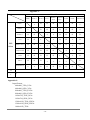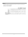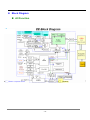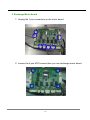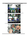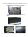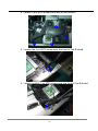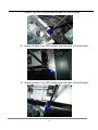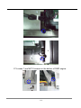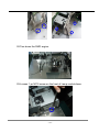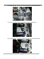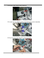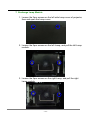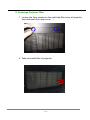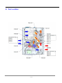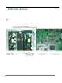
1
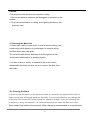
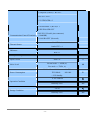
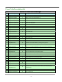
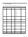
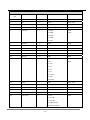
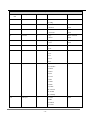
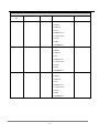
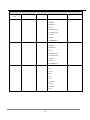
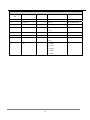
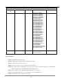
SERVICE MANUAL BARCO RLM W8 -1- Version 00 Description Initiation Date Aug. 17, 2010 -2- BARCO RLM W8 Projector PLEASE NOTE The information contained herein is based on the experience and knowledge relating to the subject matter gained by Barco prior to publication. No patent license is granted by this information. Barco reserves the right to change this information without notice, and makes no warranty, express or implied, with respect to this information. Barco shall not be liable for any loss or damage, including consequential or special damages, resulting from any use of this information, even if loss or damage is caused by Barco’s negligence or other fault. This equipment includes parts and assemblies sensitive to damage from electrostatic discharge. Use caution to prevent damage during all service procedures. -3- Table of Contents z Introduction of the product & Safety precautions z Unpack the unit z Block Diagram z Remote control use z Board location z Fan location z Cleaning unit procedure z Kits definition & Pictures z Replacing procedures z RS-232 communication z Recommended Spare Part List z Software download process z Timing chart -4- z Introduction of the product & Safety precautions BARCO (RLM W8) is compact WUXGA (1920 x 1200 Widescreen Ultra Extended Graphics Array), and 3-Chip DLP TM high-definition images projector. It shares a common mechanical, electrical, and optical platform. BARCO (RLM W8) is designed with 0.67” DMD (Digital Micro mirror Device) with 330W dual lamp. 1. Cleaning the Projector A). Cleaning the projector to remove dust and grime will help ensure trouble-free operation. 1). Be sure to turn off and unplug the projector at least 30 minutes before cleaning. Failure to do so could result in a severe burn. 2). Use only a dampened cloth when cleaning. Do not allow water to enter the ventilation openings on the projector. 3). If a little water gets into the projector interior while cleaning, leave unplugged in a well-ventilated room for several hours before using. 4). If a lot of water gets into the projector interior when cleaning, have the projector serviced. B). Cleaning the Projection Lens *When dust and fingerprints, etc. are on the lens surface, use the designated glass cleaner (toraysee) to remove it as shown in the figure at the right. For fingerprints and other soiling that are difficult to remove with a dry cloth, use a designated glass cleaner (toraysee) which has been moistened in water and then use a dry cloth to dry it off. Or, apply a little optic lens cleaner to a clean soft cloth. (Do not apply the cleaner directly to the lens.) Then, lightly wipe the lens in a circular motion. -5- Caution: *The projection lens surface has a special coating. 1. Do not use abrasive cleaners and detergents or solvents on the surface. 2. To prevent discoloration or fading, avoid getting cleaner on the projector case C). Cleaning the Main Unit 1. Clean with a soft fuzz-free cloth. In case of severe soiling, use a well-wrung cloth dipped in a neutral agent to remove soiling and then finish with a dry cloth. *Do not clean with thinner, benzene or similar agents as this could lead to deterioration or peeling of paint. 2. In case of dust in suction or exhaust holes or the interior, disassemble the main unit and use air to remove the dust from the inside. D). Cleaning the filters In order to keep the interior of the projector clean, the projector is equipped with a filter to keep out dust and other small particles. Normally, it is recommended that you change the projector's filter around 500 hours of projector operation at least. If you are operating the projector in a dusty environment, it is recommended that you clean the filter more often. When used in fog machine environment, a filter change is recommended on a regular base. -6- The interval is depending on the smoke density. Dust clogs at the filter will prevent the projector from drawing cool air to lower the internal temperature. This could lead to overheating and cause the projector to malfunction or become damaged. Use a vacuum cleaner to clean the ventilation slots. To clean the filter at the ventilation slots, refer to the following illustration: Step1: Loosen the two screws on the cover of the ventilation slot. Loosen the 2 screws -7- Step2: Remove the dirty filter; you can clean it directly using water. Leave it to dry before replacing it for further use. If the filter is broken or greasy, please replace it by a new one. (Filter Part nr: R9899704). Take out the filter and clean it Step3: Insert the clean filter. Put the clean filter inside the cover -8- Step4: Reattach the filter cover and tighten the two screws. Close the filter cover Then, fasten the two screws -9- E). Lamp Replacement The lifecycle of ordinary projection lamp typically lasts for 1500 hours before requiring replacement (different lamp configurations will affect lamp life). From the OSD Menu, you can go to LAMPS Æ Lamp1 or 2 Run Time to check how long a lamp has been used. You should also replace the lamp when the projected image gets noticeably darker. Contact your local dealer to purchase new certified lamps for your projector. To replace the projector lamp Step1: Turn off the projector and unplug the power cord. Let the projector cool for approximately 15 minutes before removing the lamp module for replacement. When you turn off the projector, the lamp inside the projector will still be very hot (approximately 200 ~ 300°C). If you attempt to replace the lamp without allowing the projector to cool, you could risk scalding yourself. This is why you should wait for no less than 15 minutes for the lamp to cool down in order to perform the replacement safely. Step2: Loosen the Lamp cover. Loosen the 2 screws - 10 - Step3: Use screwdriver to loosen the screws as shown in the illustration. Loosen the 2 screws Step4: Grasp the metal rod on the lamp cover and pull the lamp out. Pull the two Lamps Step5: Insert the new lamp in the direction shown in the illustration into the lamp assembly; tighten the two screws using a screw diver and make sure the lamp is firmly secured to prevent the lamp from shaking or poor contact. (Lamp Part nr: R9832750). - 11 - Step6: Replace the lamp cover and firmly secure the two screws on the lamp cover. Tightly lock the two screws Step7: Reconnect power to the projector and reset the lamp usage timer. Refer to OSD Menu description Æ Service Æ Lamp1, 2 Run Time. - 12 - 2. Compliance of Safe Repair Be sure to read this Service Manual before providing services. In the projector, full consideration is taken to ensure the safety for a fire, electric shock, injury, harmful radiation, and substance. Therefore, observe the notice described in this Service Manual so that the safety is kept when providing services. Moreover, be sure to observe the notice described in the Instruction Manual. Pay attention to the following during service inspection. 2-1. Cautions during disassembling and assembling 1) This equipment contains parts under high voltage. When making repairs, etc. Be sure to pull out the power plug beforehand to insure safety. 2) Parts may be very hot immediately after use. Make sure the equipment has cooled off sufficiently before carrying out repairs. 3) Make sure that parts and screws and wiring, etc. are returned to their original positions. Tube, tape and other insulation materials have been used for safety reasons. The internal wiring has been designed to avoid direct contact with hot parts or parts under high voltage when using clamps or other tools. 4) The parts used in this device have special safety features such as flame-resistance and anti-voltage properties. When replacing parts, always use parts supplied from the factory. 5) After finishing operations make sure that all parts and wires have been returned to their original position and that there has been no deterioration of the area around the location that was worked on. 6) Be sure to use an earth band (wrist band) during repair and inspection. 2-2. Lens Do not look through a lens during projection. This damages your eyes. - 13 - Technical Specification Technical Specification Feature Product Name BARCO RLM W8 Dimensions 670(L) x 517(W) x 247(H) mm < 26 Kg Weight DMD Tech. TI DLP WUXGA 0.67" 3- Chip DC3 DMD Resolution WUXGA (1920 x 1200) Lamp 330 x 2 UHP W Brightness 6300 ANSI (6600 center) (+/-10%) Lumen Lens Shift Manual - Vertical Lens Shift: + 120% & - 100% - Horizontal Shift: ± 30% Zoom & Focus Operation Zoom & Focus by remote control or local control through OSD and by projector toolset or web browser Projection Screen Size > Aspect Ratio Input/Output Terminals 8 ~ 30 / 2.4 ~ 9.1 (Native) 16: 10 1. HDMI (V1.3) x 2 2. Component 1 (YUV1) - 3 RCA x 1 3. Component 2 (YUV2) - 5 BNC x 1 4. D-sub 15 pin RGB (VGA) x 1 5. S-Video x 1 - 14 - Feet/Meter 6. Composite (Video)- 1 RCA x 1 7. RS-232C IN x 1 8. 12V TRIGGER x 2 9. IR ext. x 1 10.10/100 BASE-T (RJ-45) x 1 11. SDI IN & SDI OUT 1. RS-232C (D-sub 9 pins connector) Communication/Control Terminals (38400KB) 2. 10/100 BASE-T (Network) Inlet NTC x 1 Thermal Sensor Outlet NTC x 1 Front x 1 IR Sensor Rear x 1 AC Input Voltage 90 ~240 VAC Input Current Max 8 A A Noise Level Normal mode =< 42dB (A) Eco mode =< 37dB ( A) dB 220 V: Power Consumption Normal Mode ECO Mode < 2 W Standby 690~730 800~840 W 0 ~40 Ambient ℃ Humidity: 90% RH -20~60 ℃ Humidity: 90% RH Operation Condition Storage Condition - 15 - - 16 - Troubleshooting & Error Code System Flow chart System status Lamp Ignition - 17 - - 18 - LED Status The table for the 3 LED indicators as below: Status Blue (Stan dby) Green (Power) Red (Issue) 1. Standby 2. Lamp is approaching end of life Repeat 3. Cooling / Warm up Repeat Repeat 4. Power on / Normal 5. Lamp fail Repeat 6. Lamp door open Repeat 7. Fan fail Repeat 8. Over Temperature Repeat 9. System Error Remark: The time period of each step in the above LED blinking pattern is 500 milliseconds, e.g., for“Cooling / Warm up"state, the green LED will ON for 500 milliseconds, and then OFF 50 milliseconds, and then repeat the above LED pattern. - 19 - Error Code Description list Barco RLM W8 error message No. Error Message Led status Description 0 ErrMsgOverTempInlet: 7 Inlet (Ti) sensor over temperature (53 C) 1 ErrMsgOverTempDMD: 7 DMD(Tc) sensor over temperature(69 C) 2 ErrMsgOverTempLamp1: 7 Lamp 1 over temperature 3 ErrMsgOverTempLamp2: 7 Lamp 2 over temperature 4 ErrMsgOverTempBallast1: 7 Ballast 1 over temperature 5 ErrMsgOverTempBallast2: 7 Ballast 2 over temperature 6 ErrMsgFanInitError: 8 Fan error in powering on the projector 7 ErrMsgFan1RotateError: 6 Fan 1 rotation error 8 ErrMsgFan2RotateError: 6 Fan 2 rotation error 9 ErrMsgFan3RotateError: 6 Fan 3 rotation error 10 ErrMsgFan4RotateError: 6 Fan 4 rotation error 11 ErrMsgFan5RotateError: 6 Fan 5 rotation error 12 ErrMsgFan6RotateError: 6 Fan 6 rotation error 13 ErrMsgFan7RotateError: 6 Fan 7 rotation error 14 ErrMsgFan8RotateError: 6 Fan 8 rotation error 15 ErrMsgDMDInitFail: 8 DDP3021 communication failure in powering on the projector When one lamp fails and one lamp successes on starting the projector, it will 16 ErrMsgLampInitFail: 4 takes 6 times to ignite the fail lamp to make sure the lamp is really failed 17 ErrMsgLampLitFail: 4 Lamp 1 shut down while system is working 18 ErrMsgBallastUartError: 8 Ballast 1 UART communication failure 19 ErrMsgExGpioFail: 8 PCF 8575 external GPIO communication failure 20 ErrMsgInterLockOpen: 5 Lamp door open when system is powered on 21 ErrMsgGF9450NoResponse: 8 Gennum SPI communication failure in powering on the projector 22 ErrMsgSystemI2cFail: 8 System hardware I2C communication failure 23 ErrMsgSoftwareI2cFail: 8 System software I2C communication failure 24 ErrMsgEepromFail: 8 EEPROM check failure 25 ErrMsgEdidFail: 8 EDID check failure 26 ErrMsgEepVersionFail: 8 EEPROM version check failure 8 GSPI bus communucation failure but not entering error state (only being 27 ErrMsgRstGennum: 28 ErrMsgFan9RotateError: 6 Fan 9 rotation error 29 ErrMsgFan10RotateError: 6 Fan 10 rotation error recorded in log) - 20 - 30 ErrMsgFan11RotateError: 6 Fan 11 rotation error 31 ErrMsgFan12RotateError: 6 Fan 12 rotation error 32 ErrMsgLamp2LitFail: 4 Lamp 2 shut down while system is working 33 ErrMsgBallast2UartError: 8 Ballast 2 UART communication failure 34 ErrMsgGtInletTp: 8 Reserved 35 ErrMsgGtDmdTp: 8 Reserved 36 ErrMsgInletTempSensorFail: 8 Inlet(Ti) temperature sensor reading failure (possibly the sensor not connected) 37 ErrMsgDMDTempSensorFail: 8 DMD(Tc) temperature sensor reading failure (possibly the sensor not connected) 38 ErrMsgGeoSystemFail 8 Geo w2 detect error J11 J7 Ti sensor Tc sensor - 21 - As all above Led display and error code, they will be checked in the Error Mode when system gets error or problem. When there are two conditions as below appearing, you must enter Error Mode. 1. Lamp Extinguish 2. After system light “Red” Led, then it will enter Error Mode once system get error message again. (Ex: When Lamp A light “Red” Led, it will switch to Lamp B. Once Lamp B gets any error message, system will enter Error Mode.) The projector would echo the following messages as follow for”op prerr ": op prerr OPPRERRErrMsg: 1 SYS: 0015 . 2 SYS: 0017 3 >>> BErr= 0063 4 sys: 0032Run*LS 5 >>> BErr = 0063 6 sys: 0032Init*LS 7 >>> BErr= 0000 Illustrate above messages as follow: 1 SYS: 0015.............. ( the projector is shut down because of error code 15) 2 SYS: 0017 ...............( the projector is shut down because first lamp lite fail, lamp lite Error as below "3 >>>BErr = XXXX" ) 3 >>> BErr= XXXX .............( XXXX is the ballast error code.. usually cause the lamp fail <above SYS: 0017 > ) 4 sys: 0032Run*LS .....( the lamp is swap when projector is running because lamp lite fail, projector is still working on single lamp mode with led flash 1 times per second ) 6 sys: 0032Init*LS ........( the lamp is swap to one lamp mode on projector initial lamp process , projector is still working on single lamp mode with led flash 1 times per second ) Please refer to Error Code Description list for other error issue - 22 - J7: Inlet (Ti) sensor J11: DMD (Tc) sensor LAMP J21: Lamp A BALLAST BD J24: Lamp B - 23 - FAN Status Fan No. Function Type CN - BD Connect FAN 1 Power Fan A CN9801 FAN 2 Power Fan B FAN 3 R/G DMD Fan CN9803 FAN 5 Prism Cooling Fan CN9804 FAN 4 B DMD Fan CN9806 FAN 6 Engine Exhaust Fan FAN 8 Lamps Exhaust Fan CN9808 FAN 11 FAN 8 hub take care CN9809 FAN 9 Lamp B Blower CN9811 FAN 10 Lamp A Blower FAN 7 Lamps Cooling Fan CN9813 FAN 12 Rod cooling CN9814 CNF1 - FAN A BD CNF2 - FAN B BD CNF3 - FAN C BD - 24 - CN9802 CN9807 CN9812 RS-232 command of Fans Control statement as below: Op fan1~ fan12 = x Op fan1~fan12 ? Op fan.all ? op prerr op chevi = 0 Ex. Op fan5 = 2500 OP FAN5 = 2500 , where x is the value about the fan speed, it can be setting , it can be get fan speed , it can be get all the fan speed. , check last error code , it can be set fan speed without check environment. <- ACK Ex. Op fan5 ? OP FAN5 = 2500 Ex. Op fan.all ? OP FAN1 = 1000 . . . OP FAN12=2000 <-ACK Ex. Use command to check last error code “op prerr” 1. 10 <-ACK last 2. 5 <-ACK last sec - 25 - Please follow below three kinds of error debugging to get error code: z Use RS-232 command to get error code for debugging, please kindly refer to Page 45 (RS-232 Communication) for set-up and debugging. z Use web browser (RJ-45) to get error code for debugging. The web browser can be used to check the error code and root cause of the problem. The web browser set up configuration is as below, please press “Diagnostics” – “Advanced Diagnostics” to get error code as below interface mark: z Use Projector toolset to get error code for debugging. Projector toolset can also be used to trouble shoot the projector. - 26 - z Timing Chart 640x480 59.94 x x x 640x480 74.99 x x x 640x480 85 x x x 800x600 60.32 x x x 800x600 75 x x x 800x600 85.06 x x x 848x480 47.95 x x x 848x480 59.94 x x x 1024x768 60 x x x 1024x768 75.03 x x x 1024x768 85.03 x x x 1280x720 47.95 x x x 1280x1024 60.02 x x x 1280x1024 75.02 x x x 1280x1024 85.02 x x x 1600x1200 60 x x x 1920x1080 47.95 x x x 1680x1050 59.94 x x x 1920X1200RB 60 x x x 1920X1200 50 x x x 1400X1050 60 x x x 640x480 66.59 x x x 832x624 74.54 x x x NTSC NTSC (M, 4.43) 59.94 x x PAL PAL (B,G,H,I) 50 x x PAL (N) 50 x x PAL (M) 59.94 x x SECAM SECAM (M) 50 x x SDTV RGBS 50 1440x480i 60 x x 1440x576i 50 x x PC Apple Mac x - 27 - (EIA Timing) YUV 8-bit HDMI - (EIA Timing) RGB HDMI - YUV HD15 - RGBHV HD15 - YUV RGBHV BNC - Y-Pr-Pb SCART rate S-video Resolution Video Frame Signal Type BNC - Supported Signal Timings (DVI) EDTV HDTV 480i 59.94 x 576i 50 x 480p 59.94 x x x x x x x 576p 50 x x x x x x x 1035i 60 x x x x x x x 1080i 50 x x x x x x x 1080i (Aus) 50 x x x x x x x 1080i 59.94 x x x x x x x 1080i 60 x x x x x x x 720p 50 x x x x x x x 720p 59.94 x x x x x x x 720p 60 x x x x x x x 1080p 23.98 x x x x x x x 1080p 24 x x x x x x x 1080p 25 x x x x x x x 1080p 29.97 x x x x x x x 1080p 30 x x x x x x x 1080p 50 x x x x x x x 1080p 59.94 x x x x x x x 1080p 60 x x x x x x x - 28 - Timing name Freq. Freq. Clock H(KHz) V(Hz) (M Hz) H period H display H Sync H backp V Total V display V Sync V backp 640*480-60 31.47 59.93 25.175 800 640 96 40 525 480 2 25 640*480-75 37.5 75 31.5 840 640 64 120 500 480 3 16 640*480-85 43.27 85.01 36 832 640 56 80 509 480 3 25 800*600-60 37.88 60.32 40 1056 800 128 88 628 600 4 23 800*600-75 46.88 75 49.5 1056 800 80 160 625 600 3 21 800*600-85 53.67 85.06 56.25 1048 800 64 152 631 600 3 27 848*480-47.95 23.674 47.95 25 1056 848 80 104 497 480 5 9 848*480-59.94 29.83 59.94 31.5 1056 848 80 104 500 480 5 12 1024*768-60 48.36 60 65 1344 1024 136 160 806 768 6 29 1024*768-75 60.02 75.03 78.75 1312 1024 96 176 800 768 3 28 1024-768-85 68.88 85.03 94.5 1376 1024 96 208 808 768 3 36 1280*720-47.95 35.531 47.95 57.987 1632 1280 128 176 741 720 3 17 1280*1024-60 63.98 60.02 108 1688 1280 112 248 1066 1024 3 38 1280*1024-75 79.98 75.02 135 1688 1280 144 248 1066 1024 3 38 1280*1024-85 91.15 85.02 157.5 1728 1280 160 224 1072 1024 3 44 1600*1200-60 75 60 162 2160 1600 192 304 1250 1200 3 46 1920*1080-47.95 53.225 47.95 135.403 2544 1920 200 312 1110 1080 3 26 1680*1050-59.94 65.179 59.94 146 2240 1680 176 280 1089 1050 6 30 35 66.67 30.24 864 640 64 96 525 480 3 39 832*624-74.5 49.72 74.55 57.28 1152 832 64 224 667 624 3 39 NTSC ( M) 15.734 59.94 13.5 ─ ─ ─ ─ ─ ─ ─ ─ NTSC ( 4.43 ) 15.734 59.94 13.5 ─ ─ ─ ─ ─ ─ ─ ─ PAL ( B,G,H,I) 15.625 50 13.5 ─ ─ ─ ─ ─ ─ ─ ─ PAL ( N ) 15.625 50 13.5 ─ ─ ─ ─ ─ ─ ─ ─ PAL ( M ) 15.734 60 13.5 ─ ─ ─ ─ ─ ─ ─ ─ SECAM ( M ) 15.625 50 13.5 ─ ─ ─ ─ ─ ─ ─ ─ 640*480-66 RGBS 50 1440x480i 15.73 60 27 1716 1440 124 114 262 240 3 16 480i 15.734 59.94 13.5 858 712 63 63 262 242 3 14 1440x576i 15.62 50 27 1728 1440 126 138 312 288 3 20 576i 15.625 50 13.5 864 702 63 79 312 287 2.5 20 480p 31.47 59.94 27 858 720 62 60 525 480 6 30 576p 31.25 50 27 864 720 64 68 625 576 5 39 1920X1200RB 74.04 59.95 154 2080 1920 32 80 1235 1200 6 26 - 29 - 1920X1200 61.816 49.93 158.25 2560 1920 200 320 1238 1200 6 29 1400X1050 65.517 59.98 121.75 1864 1400 144 232 1089 1050 4 32 1035i 33.75 60 74.25 2200 1920 44 148 562 517 5 35 1080i 28.13 50 74.25 2640 1920 44 148 562 540 5 15 1080i (Aus ) 31.25 50 72 2304 1920 168 184 625 540 5 57 1080i 33.75 59.94 74.176 2200 1920 44 148 562 540 5 15 1080i 33.75 60 74.25 2200 1920 44 148 562 540 5 15 720p 37.5 50 74.25 1980 1280 40 220 750 720 5 20 720p 44.96 59.94 74.176 1650 1280 40 220 750 720 5 20 720p 45 60 74.25 1650 1280 40 220 750 720 5 20 1080p 26.97 23.98 74.175 2750 1920 44 148 1125 1080 5 36 1080p 27 24 74.25 2750 1920 44 148 1125 1080 5 36 1080p 28.13 25 74.25 2640 1920 44 148 1125 1080 5 36 1080p 33.72 29.97 74.175 2200 1920 44 148 1125 1080 5 36 1080p 33.75 30 74.25 2200 1920 44 148 1125 1080 5 36 1080p 56.25 50 148.5 2640 1920 44 148 1125 1080 5 36 1080p 67.43 59.94 148.352 2200 1920 44 148 1125 1080 5 36 1080p 67.5 60 148.5 2200 1920 44 148 1125 1080 5 36 - 30 - z Remote Control Use Projector Remote Control Below table lists the IR codes that the product is compatible with and capable of responding to. Note that there are a number of functions that are not available on the included remote. These non-remote functions are provided so that maximum functionality is available from third-party control systems and programmable remotes. Regardless of whether or not the function is included on the remote, all functions must be validated to show that they do work properly. “Keynames” refer to the RS232 codes in the next section. As shown in table, there are two complete sets of remote codes specified as Code 1 and Code 2. Through the on-screen menu, the projector can be set to either set. The reason for two sets is to allow control of more than one product in the same room without interference. The included remote control can be switched between the two sets as well (see procedure below). The projector and remote control will use the NEC IR protocol with the custom code of 0x06F9. Some details of the protocol are as follows: z The modulation frequency is 38kHz. z Each pulse consists of an on time and an off time. There are 4 types of pulses z z z z Leader pulse = 9ms “on” + 4.5 ms “off” = 13.5ms Repeat pulse= 9ms “on” + 2.25 ms “off” = 11.25 ms 0 pulse = .56ms “on” + .56ms “off” = 1.12ms 1 pulse = .56ms “on” + .1.68ms “off” = 2.24ms z A key code will be a leader followed by 32 data pulses. The first 16 comprise the custom code 0x06F9. The next 16 are the key data (8 bits) followed by the complement of the key data. z A key held down will generate a repeat pulse only. Table : Barco IR Codes & Keynames No. Code 1 Code 2 RS232 Keyname Remote Description Button 0-1 0x01 0xB7 power.on Turn power on. - 31 - Table : Barco IR Codes & Keynames No. Code 1 Code 2 RS232 Keyname Remote Description Button 0-2 0x09 0xB9 power.off 0-3 0x15 0xBA menu Turn power off. Bring up or cancel menu display. MENU 0-4 0x17 0xBB enter Keypad enter. ENTER 0-5 0x18 0xBC cur.down Keypad down arrow. 0-6 0x1A 0xBD cur.up Keypad up arrow. 0-7 0x1D 0xBE cur.left Keypad left arrow. 0-8 0x1F 0xBF cur.righ Keypad right arrow. 0-9 0x80 0xC0 bright Bring up or cancel brightness slider. 0-10 0x81 0xC1 contrast Bring up or cancel contrast slider. 0-11 0x82 0xC2 sharp Bring up or cancel sharpness slider. SHARPN 0-12 0x83 0xC3 tint Bring up or cancel tint slider. TINT 0-13 0x85 0xC5 phase Bring up or cancel phase slider. PHASE 0-14 0x8B 0xCB src.1 Switch the active source to source 1. 0-15 0x8C 0xCC src.2 Switch the active source to source 2. - 32 - Table : Barco IR Codes & Keynames No. Code 1 Code 2 RS232 Keyname Remote Description Button 0-16 0x8D 0xCD src.3 Switch the active source to source 3. 0-17 0x8E 0xCE src.4 Switch the active source to source 4. 0-18 0x8F 0xCF src.5 Switch the active source to source 5. 0-19 0x93 0xD3 saturat 0-20 0x98 0xD8 pause 0-21 0x99 0xD9 text COLOR P AUSE Switch to the next color sturation mode. Switch the pause key. Switch the text on/off mode. TEXT 0-22 0x9A 0xDA auto.img Switch the auto image key. AUTO IMAGE 0-23 0x9D 0xDD asp.sw Switch to the next aspect ratio. 0-24 0xA3 0xE3 pip.sw Switch to next “PIP Select” state. 0-25 0xAA 0xEA pip.swap Swap the PIP image with the active source image. 0-26 0xAD 0xED address Activates remote backlighting only when pressed momentarily. ADDRESS When held for 5 seconds or more the IR code for toggling the projector IO light will be transmitted. - 33 - For the included remote control, the following is required: • The projector and the remote shall be designed together to have a 40 feet range from the front of the projector and a 20 feet range from the top. • The dispersion angle from the IR emitter(s) shall be at least 15 degrees. • There are 2 independent sets of NEC HEX codes with identical control (identified as Code 1 and Code 2 in Table ). • The method to switch the remote to the other code set is to hold down the “Address” and “Enter” keys simultaneously for 5 seconds. While these two keys are pressed there will be no IR transmission. When the code set has changed the remote will blink the back-lighting once as a visual confirmation of the change. • The buttons are to be back-lighted with red (625-670nm) LEDs. The back-lighting will turn on after any key press. The back-lighting will turn off during IR transmission as feedback that a key is being pressed and that transmission is occurring. The backlighting will stay on for 10 seconds after any key is pressed or until the “Address” button is pressed again. Key icons and text must be clearly visible from 2 feet away when the back-lighting is on in a dark room. • The key trip force shall be 135 +/- 35 grams • 2 AA batteries to be used. The lifetime of the remote should be approximately 6 months under normal use conditions with alkaline batteries. • The remote control button layout is shown in Figure 1. - 34 - Figure 1: IR Remote Control Layout For the projector IR interface, the following is required: • The projector and the remote shall be designed together to have a minimum 40 feet range from the front of the projector and a minimum 20 feet range from the top. • The IR receivers should be placed so that the projector has an angular range as shown in Figure 2. - 35 - Figure 2: IR Reception Angles - 36 - Remote Control Installation - 37 - z Software Download Process Projector firmware Download procedures 1. Firmware downloads procedure: 1-1. Connect the AC power of the projector and have the projector in standby mode. 1-2. Connect the RS-232 cable between the projector and the PC. 1-3. Open the Firmware Upgrade Tool accompanied with the firmware release. 1-4. Click the RS232 from menu to select the correct COM port number corresponding to the connection. 1-5. Click the “Projector communication test” button for testing the communication with the projector. If everything is OK, the following dialog box will be shown. 1-6. Click the “Open File” button to activate the file selection dialog box and select BarcoW8.txt (or BarcoW8.txt) file under the same folder of the firmware release. - 38 - 1-7. Click “Upgrade SW” to start the firmware upgrades process. Prior to the firmware upgrade process, you will be prompted with a warning dialog box for confirmation and click “Yes” to proceed the firmware upgrade process. st 1-8. The firmware upgrade process indicator of Micro-Control board (The 1 part of this firmware upgrade process) will be shown as follows, st 1-9. After finishing the firmware upgrade of the Micro-Control board (1 part), the firmware nd upgrade process of the video board (2 part) will be started after then. A DOS command box with the ISP program will be activated and shown as follows, - 39 - 1-10. Depending on the file size of the firmware, it may take about 12 ~ 25 minutes before the firmware upgrading can be finished. The following dialog box will be shown after finishing the firmware upgrade process. Click “OK” button and “Exit” from the menu to exit from the whole firmware upgrade process. 1-11. After finishing the firmware upgrade process, please recycle the AC power. 2. Firmware downloads procedure for sxW2 part: 2-1. Connect the AC power of the projector and have the projector in standby mode. 2-2. Connect the RS-232 cable between the projector and the PC. 2-3. Open a terminal program (e.g. Tera Term) with the following setting, baud rate 38400, Databit: 8, Parity: none, Stop: 1 bit, Flow control: none. - 40 - 2-4. Input the command “op dlw2 = 1” on the terminal 2-5. Close and Exit the terminal program. 2-6. Activate the sxW2 firmware Updater program for the firmware upgrade of sxW2 chip. And select “UART” in the “Targets on” - 41 - 2-7. Click “Search” button, the available COM port (likes COM:1) will be listed after searching and shown as follows 2-8. Click on the available COM port (e.g. COM: 1 in this example) and select the target firmware (Image File) by clicking the “Browse …” button. 2-9. After selecting the firmware file, press the “Update Firmware” to start the firmware upgrade process. 2-10. The firmware upgrade status will be shown on the status bar of the firmware updater to indicate the progress of this firmware download. 2-11. After finishing the firmware download, please recycle the AC switch to finish the overall firmware download process of sxW2. 3. Firmware downloads procedure for RJ-45 module: 3-1. Connect the AC power of the projector and have the projector in standby mode. 3-2. Connect the RJ-45 cable between the projector and the PC. And make sure that the two LEDs of the RJ-45 module are lit after connecting the RJ-45 cable between the PC and the projector. If the LEDs are not lit, please send the RS command “eco.net.pow = 0” on the terminal to turn on the RJ-45 module. 3-3. Properly setup the IP for the PC and make sure that the PC and the projector are in the same subnet. For example, the default IP of the projector is 192.168.0.100. So the IP of the PC should be set as 192.168.0.99 for example. - 42 - 3-4. Key in the projector IP on the web browser (the recommended web browser is IE 6.0 or later version, the default IP is 192.168.0.100) to see the embedded webpage. The IP can be accessed via the RS command “op net.ipaddr ?” with a terminal program. 3-5. Make sure the DHCP is “Disable”, if current state is “Enable”, switch it to “Disable” and click “Save” button to save the setting. - 43 - 3-6. Key in the IP address and followed by “/firmwareUpdate.htm” on the URL box as below to activate the firmware update procedure http://192.168.0.100/firmwareUpdate.htm And click the “Update” button to start the firmware upgrade process. 3-7. The following message will be shown on the display, click “Continue” button to proceed 3-8. Press the “Browse” button and locate the firmware (binary code) to be upgraded. Then press the “Upgrade” button to proceed the download process. - 44 - Browse 3-9. Wait until the firmware upgrade process finished. Browse 3-10. The following message will be shown after the firmware upgrade procedure. Just press the “Re Login” button to finish the whole firmware upgrade process of RJ-45 module. - 45 - 3-11. RJ-45 Test procedures Key in your Projector IP to web browser Information - 46 - 4. Barco RLM W6/W8 Ballast Firmware upgrade procedure Ballast Firmware upgrade procedure: 1. Before proceeding the following ballast firmware upgrade procedure, please download and install Osram Unishape tool (OsramFlashX) from Osram Website. 2. Connect the AC power of the projector and have the projector in standby mode. 3. Connect the RS-232 cable between the projector and the PC and make sure that the “Projector Control” is configured as “RS232”, if not, please use the hotkey to switch the “Projector Control” as “RS232”. 4. Open a terminal program (e.g. Tera Term) with the following setting, baud rate 38400, Databit:8, Parity: none, Stop:1 bit, Flow control: none. 5. 6. 7. Power on the projector and wait for the completion of the powering on sequence. It takes about 90 seconds for the completion of the powering on sequence. Input the command “op dlba1” on the terminal and then disconnect the connection and close the terminal program. Activate Osram Unishape Flash tool (OsramFlashX) and press the “Auto-detect” button to find the communication port with the ballast. As shown in the following diagram, COM1 is detected as the communication port to talk to the ballast. - 47 - 8. Press “Browse” button and then locate and select the new ballast firmware to be flashed. 9. Press “Program” button to start the ballast firmware update. is proceeding, you will see a progress indicator as follows. 10. Wait until the firmware update process finished as follows, - 48 - While the firmware update process 11. Switch off the AC power of the projector. 12. Repeat the above steps #2 ~ #11 for the firmware upgrade of the other ballast and in step #6, please input the command “op dlba2” to specify ballast2 as the target ballast to be updated. The other steps are the same. - 49 - After finishing downloading all software in projector, please go to OSD to check your revision confirmation or go to RS-232 to command for confirmation. (A). OSD (B). RS-232 Please key in “op sw.ver ?” And, you can get all software revision. Or, please key in “op soft.version ?” And, you can get more detail software revision. - 50 - z RS-232 Communication RS-232 Operation Executive Command z Interface and Requirements The RS-232 Commands use only ASCII characters which can be entered using a typical terminal emulator like Windows HyperTerminal with the following setting: Bits per second: 38400 Data bits: 8 Parity: None Stop bits: 1 Flow control: None Note that each input character will be echoed on the terminal by MCU and there is no need to set the local echo “ON” with the terminal setting. z System Operation commands. The Operation commands tell the projector what to do. All commands start with 2 letters: “op” for operations commands, and a space [SP] then following a control command then finally the value wants to read, set, increase or decrease. All commands must end with a carriage return (ASCII hex 0D), shown as [CR] below. The syntax for operations commands is as follows: op[SP]<operation command>[SP]<Setting Value>[CR] For all but Execute functions the response from the projector will be the command and “= <value>” where <value> is the current value or “NA” if the value is not available. For Execute functions the response will be the same command. All responses will be in CAPS. Please refer to the following table for command list and examples: System Operation command: Operation Commands Values Set = <value> Makes the unit take that value. Get ? Asks what the current value is. Increment + Adds 1 to the current value. Decrement - Subtracts 1 from the current value. - 51 - Operation Execute Commands (none) Values Performs an action such as a reset. Motor operation command: For motor control like lens shift, focus and zoom, the parameters “+” and “-” are defined as follows. Command item focus command + - System Action + => Focus Near, - => Focus Far zoomio + - + => Zoom out - => Zoom in vert.offset + - + => Up - => Down horiz.offset + - + => Right - => Left Lens.center (execute) Midposition shift Get operations command example: Input: op bright ? [CR] System Response: OP BRIGHT = 100 Increase & Decrease operations command examples: Input: op bright + [CR] System Response: OP BRIGHT = 101 Input: op bright - [CR] Response: OP BRIGHT = 126 Set operations command example: Input: op bright = 127 [CR] System Response: OP BRIGHT = 127 Execute command example: - 52 - Input: op auto.img [CR] Response: OP AUTO.IMG The list of valid operation commands for Barco RLM W8 is shown in below Table. Barco RLM W8 Operation Commands Command Operation Commands Values Notes Item 1-1 input.sel =? 0 = HDMI 1 Note1; Note3 1 = HDMI 2 2 = RGB D-15 3 = YUV 1 4 = RGBHV/YUV2 5 = Composite Video 6 = S-Video 7 = RGB-S 8 = SDI/HDSDI/3G 1-2 input.lock =? 0 = Auto Note2 1 = 48 Hz 2 = 50 Hz 3 = 60 Hz 1-3 auto.powoff =? 0 = Off Note1 1 = On 1-4 auto.powon =? 0 = Off 1 = On 1-5 no.signal =? 0 = Logo Note1 1 = Blue 2 = Black 3 = White 1-6 vid.std =? 0 = Auto Note2; Note4 1 = PAL 2 = SECAM 3 = NTSC 1-7 auto.imgadj = ? 0 = Off Note2 1 = Auto 2 = Always 2-1 contrast = ?+- 0 - 200 Note2 2-2 bright = ?+- 0 - 200 Note2 - 53 - Barco RLM W8 Operation Commands Command Operation Commands Values Notes Item 2-3 saturat = ?+- 0 - 200 Note2; Note4 2-4 tint = ?+- 0 - 200 Note2; Note4 2-5 sharp = ?+- 0 - 200 Note2 2-6 nr = ?+- 0 - 200 Note2 2-7 color.temp = ? 0 = 3200K Note2; 1 = 5400K Note8 2 = 6500K 3 = 9300K 4 = Native 2-8 red.offset = ?+- 0-200 Note2 2-9 green.offset = ?+- 0-200 Note2 2-10 blue.offset = ?+- 0-200 Note2 2-11 red.gain = ?+- 0-200 Note2 2-12 green.gain = ?+- 0-200 Note2 2-13 blue.gain = ?+- 0-200 Note2 2-14 aspect =? 0 = 5:4 Note2; 1 = 4:3 Note5 2 = 16:10 3 = 16:9 4 = 1.88 5 = 2.35 6 = Letterbox 7 = Native 8 =Unscaled 2-15 h.total = ?+- 0-200 Note2 ; Note7 2-16 h.pos = ?+- 0-200 Note2 2-17 h.phase = ?+- 0-200 Note2; Note7 2-18 v.pos = ?+- 0-200 Note2 2-19 auto.img (execute) 2-20 Color.space2 =? Note2 0 = Auto 1 = YUV HD 2 = YUV STD 3 = RGB-PC(0-255) 4 = RGB-Video(16-255) - 54 - Note2 Barco RLM W8 Operation Commands Command Operation Commands Values Notes Item 3-1 zoom =? 0 = Off Note2; Note6 1 = Crop 2 = Zoom 3-2 pip.sel =? 1 = HDMI 1 Note1; 2 = HDMI 2 Note9; 3 = RGB D-15 Please refer to appendix 1 4 = YUV 1 for the valid main/pip 5 = RGBHV/YUV2 source selection 6 = Composite Video 7 = S-Video 8 = RGB-S 9 = SDI/HDSDI/3G 3-3 pip.pos =? 0 = Top left Note1; 1 = Top right Note10 2 = Bottom left 3 = Bottom right 4 = Split L-R 3-4 pip =? 0 = Off Note1 1 = On 4-1 lamp.mode =? 0 = Economy Note2 1 = Standard 2 = Dimming 4-2 4-3 lamps altitude =? =? 0 = Single Note1; 1 = Dual Note11 0 = Off Note1 1 = On 4-4 lamp.pwr =? 0-19 ( 85 % ~100.0 % ) Note2 4-5 lamp1.stat ? 0 = Off Note1 1 = On 4-6 lamp2.stat ? 0 = Off Note1 1 = On 5-1 rear.proj =? 0 = front 1 = rear - 55 - Note1 Barco RLM W8 Operation Commands Command Operation Commands Values Notes Item 5-2 ceil.mode =? 0 = floor Note1 1 = ceiling 5-3 5-4 5-5 5-6 5-7 zoomio focus vert.offset horiz.offset dyna.cont +- +- +- +- =? + = Zoom out Motor command; - = Zoom in Note1 + = Focus Near Motor command; - = Focus Far Note1 + = Up Motor command; - = Down Note1 + = Right Motor command; - = Left Note1 0 = Off Note2 1 = On 5-8 gamma =? 0 = 1.8 Note2 1 = 2.0 2 = 2.2 3 = 2.35 4 = 2.5 5-9 int.ptrn =? 0 = Off Note1 1 = Color Bars 2 = Hatch 3 = Burst 4 = Red 5 = Green 6 = Blue 7 = White 8 = Black 9 = TI-Red 10 = TI-Green 11 = TI-Blue 12 = TI-Ramp 5-10 color.space =? 0 = Native 1 = EBU 2 = SMPTE 3 = Custom - 56 - Note2 Barco RLM W8 Operation Commands Command Operation Commands Values Notes Item 5-10a Lens.center (execute) Note1 5-11 h.keystone = ?+- -350~+350 Note1; Note15 5-12 v.keystone = ?+- -200~+200 Note1; Note15 5-13 warp.rotat =?+- -20~ +20(in ¼∘unit) Note1 5-14 warp.pinbrl =?+- -100 ~ +100 Note1 5-16 warp.tlc.x =?+- ‘x: -192 ~ +192 Note1 warp.tlc.y 5-17 warp.trc.x ‘y: -120 ~ +120 =?+- ‘x: -192 ~ +192 warp.trc.y 5-18 warp.blc.x ‘y: -120 ~ +120 =?+- ‘x: -192 ~ +192 warp.blc.y 5-19 warp.brc.x Note1 Note1 ‘y: -120 ~ +120 =?+- ‘x: -192 ~ +192 warp.brc.y Note1 ‘y: -120 ~ +120 5-19a warp.reset (execute) Note1 5-19b w2.recover (execute) Note1 5-20 blank.top =?+- 0 ~ 360 Note1 5-21 blank.btm =?+- 0 ~ 360 Note1 5-22 blank.left =?+- 0 ~ 534 Note1 5-23 blank.right =?+- 0 ~ 534 Note1 5-23a blank.rst (execute) 5-24 scen.stat =? Note1 0 = Off Note1 1 = On 5-25 scen.wht.top =?+- 0 ~ 500 Note1 ; Note 16 =?+- 0 ~ 800 Note1 ; Note 16 =?+- 0 ~ 32 Note1; Note 17 multiple scen.wht.btm 5-26 scen.wht.left scen.wht.right 5-27 scen.blk.top scen.blk.btm of 8;the adjustable range and 8-multiple restrictions are per Geo Semi’specification. - 57 - Barco RLM W8 Operation Commands Command Operation Commands Values Notes Item 5-28 scen.blk.left =?+- 0 ~ 32 scen.blk.right Note1 ; Note 17 multiple of 4;the adjustable range and 4-multiple restrictions are per Geo Semi’specification. 5-29 scen.red =?+- 0 ~ 32 Note1 5-30 scen.green =?+- 0 ~ 32 Note1 5-31 scen.blue =?+- 0 ~ 32 Note1 5-32 scen.all =?+- 0 ~ 32 Note1;Note18 5-33 scen.reset (execute) 5-34 scen.adl =? Note1 0 = Off Note1 1 = On 6-1 ir.addr =? 0 = remote code 1 1 = remote code 2 6-2 eco.net.pow =? 0 = Off (RJ45 Power On) 1 = On (RJ45 Power Off) 6-3 proj.ctrl =? 0 = rs232 Note12 1 = network 6-4 net.ipaddr =? <string> 6-5 net.subnet =? <string> 6-6 net.gateway =? <string> 6-7 net.dhcp =? 0 = Off 1 = On 6-8 menu.pos =? 0 = Top left 1 = Top right 2 = Bottom left 3 = Bottom right 4 = center 6-9 startup.logo =? 0 = Off 1 = On 6-10 startup.chime =? 0 = Off 1 = On - 58 - Note1 Barco RLM W8 Operation Commands Command Operation Commands Values Item 6-11 btn.1 =? 0 = HDMI 1 1 = HDMI 2 2 = RGB D-15 3 = YUV 1 4 = RGBHV/YUV2 5 = Composite Video 6 = S-Video 7 = RGB-S 8 = SDI/HDSDI/3G 6-12 btn.2 =? 0 = HDMI 1 1 = HDMI 2 2 = RGB D-15 3 = YUV 1 4 = RGBHV/YUV2 5 = Composite Video 6 = S-Video 7 = RGB-S 8 = SDI/HDSDI/3G 6-13 btn.3 =? 0 = HDMI 1 1 = HDMI 2 2 = RGB D-15 3 = YUV 1 4 = RGBHV/YUV2 5 = Composite Video 6 = S-Video 7 = RGB-S 8 = SDI/HDSDI/3G - 59 - Notes Barco RLM W8 Operation Commands Command Operation Commands Values Notes Item 6-14 btn.4 =? 0 = HDMI 1 1 = HDMI 2 2 = RGB D-15 3 = YUV 1 4 = RGBHV/YUV2 5 = Composite Video 6 = S-Video 7 = RGB-S 8 = SDI/HDSDI/3G 6-15 btn.5 =? 0 = HDMI 1 1 = HDMI 2 2 = RGB D-15 3 = YUV 1 4 = RGBHV/YUV2 5 = Composite Video 6 = S-Video 7 = RGB-S 8 = SDI/HDSDI/3G 6-16 trig.1 =? 0 = 5:4 1 = 4:3 2 = 16:10 3 = 16:9 4 = 1.88 5 = 2.35 6 = Letterbox 7 = Native 8 = Unscaled 9 = Auto - 60 - Note1 Barco RLM W8 Operation Commands Command Operation Commands Values Notes Item 6-17 trig.2 =? 0 = 5:4 Note1 1 = 4:3 2 = 16:10 3 = 16:9 4 = 1.88 5 = 2.35 6 = Letterbox 7 = Native 8 = Unscaled 9 = Auto 6-18 auto.src =? 0 = Off Note1 1 = On 6-19 lang =? 0 = English 1 = French 2 = Spanish 3 = German 4 = Portuese 5 = Chinese Simplified 6 = Chinese Traditional 7 = Japanese 8 = Korean 7-1 model ? <string> 7-2 ser.no ? <string> 7-3 sw.ver ? <string> Note13 7-4 act.src ? 0 = HDMI 1 Note1 1 = HDMI 2 2 = RGB D-15 3 = YUV 1 4 = RGBHV/YUV2 5 = Composite Video 6 = S-Video 7 = RGB-S 8 = SDI/HDSDI/3G - 61 - Barco RLM W8 Operation Commands Command Operation Commands Values Notes Item 7-5 pip.src ? 0 = Off Note1 1 = HDMI 1 2 = HDMI 2 3 = RGB D-15 4 = YUV 1 5 = RGBHV/YUV2 6 = Composite Video 7 = S-Video 8 = RGB-S 9 = SDI/HDSDI/3G 7-6 pixel.clock ? <string> In MHz ; Note2 7-7 signal ? <string> Note2 7-8 h.refresh ? <string> Note2 7-9 v.refresh ? <string> Note2 7-10 lamp1.hours ? <string> 7-11 lamp2.hours ? <string> 7-12 lamp1.reset (execute) 7-13 lamp2.reset (execute) 7-14 proj.runtime 7-15 blue.only ? <string> =? 0 = Off Note1 1 = On 7-16 fact.reset (execute) 8-1 CS_cust_Rx =? 000 ~ 999 P7 Command; Note1 8-2 CS_cust_Ry =? 000 ~ 999 P7 Command; Note1 8-3 CS_cust_Gx =? 000 ~ 999 P7 Command; Note1 8-4 CS_cust_Gy =? 000 ~ 999 P7 Command; Note1 8-5 CS_cust_Bx =? 000 ~ 999 P7 Command; Note1 8-6 CS_cust_By =? 000 ~ 999 P7 Command; Note1 8-7 CS_cust_Wx =? 000 ~ 999 P7 Command; Note1 8-8 CS_cust_Wy =? 000 ~ 999 P7 Command; Note1 8-9 CS_cust_Cx =? 000 ~ 999 P7 Command; Note1 8-10 CS_cust_Cy =? 000 ~ 999 P7 Command; Note1 8-11 CS_cust_Mx =? 000 ~ 999 P7 Command; Note1 - 62 - Barco RLM W8 Operation Commands Command Operation Commands Values Notes Item 8-12 CS_cust_My =? 000 ~ 999 P7 Command; Note1 8-13 CS_cust_Yx =? 000 ~ 999 P7 Command; Note1 8-14 CS_cust_Yy =? 000 ~ 999 P7 Command; Note1 0.1 picture.mute =? 0 = Off 1 = On 0.2 power.on (execute) 0.3 power.off (execute) 0.4 text.mode =? 0 = Off 1 = On 0.5 status ? 0 = standby 1 = warm up 2 = imaging 3 = cooling 4 = warning - 63 - Note14 Barco RLM W8 Operation Commands Command Operation Commands Values Notes Item 0.6 errcode ? 0.7 f.search =? 0=ErrMsgOverTempInlet: 1=ErrMsgOverTempDMD: 2=ErrMsgOverTempLamp1: 3=ErrMsgOverTempLamp2: 4=ErrMsgOverTempBallast1: 5=ErrMsgOverTempBallast2: 6=ErrMsgFanInitError: 7=ErrMsgFan1RotateError: 8=ErrMsgFan2RotateError: 9=ErrMsgFan3RotateError: 10=ErrMsgFan4RotateError: 11=ErrMsgFan5RotateError: 12=ErrMsgFan6RotateError: 13=ErrMsgFan7RotateError: 14=ErrMsgFan8RotateError: 15=ErrMsgDMDInitFail: 16=ErrMsgLampInitFail: 17=ErrMsgLampLitFail: 18=ErrMsgBallastUartError: 19=ErrMsgExGpioFail: 20=ErrMsgInterLockOpen: 21=ErrMsgGF9450NoResponse: 22=ErrMsgSystemI2cFail: 23=ErrMsgSoftwareI2cFail: 24=ErrMsgEepromFail: 25=ErrMsgEdidFail: 26=ErrMsgEepVersionFail: 27=ErrMsgRstGennum: 28=ErrMsgFan9RotateError: 29=ErrMsgFan10RotateError: 30=ErrMsgFan11RotateError: 31=ErrMsgFan12RotateError: 32= ErrMsgLamp2LitFail: 33= ErrMsgBallast2UartError: 34=ErrMsgGtInletTp: 35=ErrMsgGtDmdTp, 36=ErrMsgInletTempSensorFail, 37=ErrMsgDMDTempSensorFail, 38=ErrMsgGeoSystemFail 0 = F1 Search 1 = F2 Search (default) REMARK: An input command will get back with “NA” when the input command is “Not Applicable” in some specific conditions. Note1: Not applicable in standby mode. Note2: Not applicable in standby mode or without signal locked. Note3: Not applicable when picture mute is on. Note4: Only valid when source is one of Composite, S-Video and RGB-S. Note5: Native aspect ratio is not applicable when zoom is set to “Zoom”, Letterbox aspect ratio is not applicable when the input format is one of formats as listed in appendix 2. Note6: Selection “Zoom” is not applicable when aspect ratio is set to Native. Note7: Only applicable when source is one of RGB D-15, YUV1 and RGBHV/YUV2. Note8: Not applicable when color space is set to custom. - 64 - Note9: pip.sel can NOT be set to 0. Note10: Not applicable when pip is off. Note11: Not applicable when lamp is cooling. Note12: Not applicable when eco.net.pow is on. Note13: Only MCU version number will be read back in standby mode. Note14: Not applicable when the internal pattern is displayed. Note15: The summation of the absolute value of h.keystone and v.keystone should not be greater than 350. Note16: Per Geo Semi’s specification, the minimum blend size is 200, values in the range 1 ~ 99 are not allowed if no 4-corner adjustment, values in the range 1~ 199 are not allowed if there is 4-corner adjustment. Note17: Per Geo Semi’s specification, black level (position) adjustment will only work with an active white level setting on the corresponding side. Note18: When scen.red, scen.green, scen.blue values are not equal, the command will get back “NA"in reading. - 65 - Appendix 1: Main Select HDMI 1 - HDMI 1 PIP Select HDMI 2 RGB D-15 RGBHV / Composite YUV 2 Video YUV 1 S-Video RGB-S SDI/HDSDI/3G O O O O O O - O O O O O O - - - O O O O - O O - O O O - O - - O - O HDMI 2 - RGB D-15 O O YUV 1 O O - RGBHV / YUV 2 O O - - Composite Video O O O O O S-Video O O O O O - RGB-S O O O - - - - SDI/HDSDI/3G - - O O O O O O Source Available - NA Appendix 2: Input Format: 640x480_75Hz_VGA: 640x480_85Hz_VGA: 800x600_75Hz_SVGA: 800x600_85Hz_SVGA: 1024x768_75Hz_XGA: 1024x768_85Hz_XGA: 1280x1024_75Hz_SXGA: 1280x1024_85Hz_SXGA: 1400x1050_75Hz - 66 - O O Appendix 3: The allowable combinations of warp, blanking and ScenergiX were summarized as the following table X indicates a not-allowed combination OK indicates a allowed combination - 67 - z Block Diagram All Function - 68 - Power Function Dual Ballast (330W x 2) (CN102, Q106) - 69 - z Replacing Procedures 1. Top cover disassembly 1. Loosen the 14 pcs M4*6 screws. 2. Open the top cover and take off the top cover. - 70 - z Board Location - 71 - 2. Exchange Motor board 1. Unplug the 7 pcs connectors on the motor board. 2. Loosen the 4 pcs M3*6 screws then you can exchange motor board. - 72 - 3. Exchange Fan A / Fan B / Fan C board 1. Loosen each 2 pcs M3*6 screws then you can exchange Fan A / Fan B / Fan C board. - 73 - 4. Exchange Micro control board / Video board / W2 board / RJ-45 board / Keypad board / IR board 1. Loosen 7 screws then take off the cover bracket. 2. Open the cover of control module and take off it. - 74 - 3. Loosen 4 pcs M4*6 screws on the right side of back cover. 4. Loosen 3 pcs M4*6 screws on the terminal side of back cover. - 75 - 5. Loosen 4 pcs M4*6 screws on the left side of back cover. 錯誤! 6. Loosen 2 pcs long hex-screws on the AC power of back cover and 2 pcs M4*6 screws on the bottom of back cover. - 76 - 7. Loosen 1 pc M4*6 screw on the control module. 8. Unplug the 2 pcs connectors from back cover, and then tear down the back cover. - 77 - 9. Pull the rear cover and take off it. 10. Loosen 1 pc M3*6 screw on the back cover, and then tear down the back IR board. - 78 - 11. Loosen 4 pcs M3*6 screws on the back cover, and then tear down the Keypad board. 12. Unplug the 3 pcs connectors on the left side of W2 board. - 79 - 13. Unplug the 3 pcs connectors on the right side of W2 board. 14. Unplug the 8 pcs connectors on the right side of Micro control board. - 80 - 15. Unplug the 7 pcs connector on the left side of Micro control board. 16. Unplug the 1 pc connector on the video board. - 81 - 17. Loosen the 16 pcs screws on the rear cover. 18. Pull the whole control module. - 82 - 19. Loosen the 3 pcs M3*6 screws on the Micro control board. 20. Disconnect the left connector under Micro control board. - 83 - 21. Disconnect the right connector under Micro control board. 22. Pull the Micro control board. - 84 - 23. Unplug the connector and loosen 1 pc M3*6 screws on the RJ-45 board. 24. Loosen 2 pcs M3*6 screws on the bracket. - 85 - 25. Strip down the bracket from control module. 26. Loosen the 7 pcs M3*6 screws on the video board. - 86 - 27. Strip down the video board. 28. Loosen the 4 pcs M3*6 screws on the W2 board. - 87 - 29. Strip down the W2 board. - 88 - 5. Exchange ballast board / power board 1. Remove the 1 pc M3*6 screws on the bracket. 2. Tear down and take off the bracket. 3. Loosen the 4 pcs M4*6 screws on right of right side cover of projector. - 89 - 4. Loosen the 4 pcs M4*6 screws on bottom of right side cover of projector. 5. Loosen the 2 pcs M3*6 screws on surface of power module. 6. Loosen the other 3 pcs M3*6 screws on surface of power module. - 90 - 7. Loosen the 1 pc M3*6 screws on top right root of power module. 8. Loosen the 1 pc M3*6 screw on top left root of power module. 9. Loosen the 1 pc M3*6 screw on down left root of power module. - 91 - 10. Loosen the 1 pc M3*6 screw on down right root of power module. 11. Unplug the 2 pcs lamp high-voltage connectors from power module. 12. Loosen the 4 pcs M3*6 screws on side of power module. - 92 - 13. Open the top cover of power module upward. 14. Be careful to pull the wire from indentation of power module. 15. Unplug the 8 pcs M3*6 screws and tear down the 2 pcs ballasts. - 93 - 16. Loosen the 3 pcs M3*6 screws on the top of power board. 17. Loosen the 3 pcs M3*6 screws on the down of power board. 18. Tear down power board from power module. - 94 - 6. Exchange DMD Engine / Integrator System Assembly 1. Loosen the 4 pcs M4*6 screws on the left of left side cover of projector. 2. Loosen the 4 pcs M4*6 screws on the down of left side cover of projector. 3. Loosen 6 pcs M3*6 screws to remove bracket. - 95 - 4. Loosen 5 pcs φ3*6 screws and take off the bracket. 5. Loosen the 1 pc M3*6 screw near the front of Fan B board. 6. Loosen another 1 pc M3*6 screw near the front of Fan B board. - 96 - 7. Loosen 1 pc M3*6 screw near the back of Fan B board. 8. Loosen another 1 pc M3*6 screw near the back of Fan B board. 9. Loosen another 1 pc M3*6 screw near the back of Fan B board. - 97 - 10. Take off the top cover module of air output. 11. Loosen 3 pcs M4*10 screw and take off the bottom cover module of air output. 12. Loosen 1 pc M3*6 screw on bracket of FIP. - 98 - 13. Loosen another 1 pc M3*6 screw on bracket of FIP. 14. Loosen another 1 pc M3*6screw on bracket of FIP. 15. Loosen 1 pc M3*6 screw on the bracket of Fan 9 & Fan10 board. - 99 - 16. Take off the bracket of FIP. 17. Loosen 1 pc M3*6 screw on the bracket of Fan 9 & Fan10 board. 18. Loosen 1 pc M3*6 screw on the bracket of Fan 9 & Fan10 board. - 100 - 19. Take off the bracket of Fan 9 & Fan10 board. 20. Loosen 3 pcs M3*6 screws and take off the bracket of FIP. 21. Loosen 2 pcs M4*10 screws on Lens Mount cover. - 101 - 22. Loosen 2 pcs M4*10 screws on bottom of Lens Mount cover. 23. Loosen 1 pc M4*8 screws to remove front panel. 24. Push the small front panel from right to left. - 102 - 25. Tear down the small front panel. 26. Loosen 4 pc M3*6 screws on bottom of front cover, then take off the front cover. - 103 - 27. Loosen 7 pcs M4*10 screws on the bottom of DMD engine. - 104 - 28. Tear down the DMD engine. 29. Loosen 1 pc M3*6 screw on the front of Lamp module base. - 105 - 30. Loosen another 1 pc M3*6 screw on the front of Lamp module base. 31. Loosen 1 pc M3*6 screw on the back of Lamp module base. 32. Loosen another 1 pc M3*6 screw on the back of Lamp module base. - 106 - 33. Pull the Lamp module base toward left. 34. Loosen the 2 pcs M3*6 screws on the illumination system assembly. 35. Take off and pull the integrator system assembly. - 107 - 36. Put back relay Lens on illumination base. ** Note: When we take off integrator system assembly, the relay Lens will be adhered to integrator system assembly. Thus, we need to take off relay Lens from integrator system assembly. Then, we must clean any dust, dirt and fingerprint, and put back. - 108 - 7. Exchange Lamp Module 1. Loosen the 2pcs screws on the left side Lamp cover of projector, then and open the Lamp cover. 2. Loosen the 2pcs screws on the left Lamp, and pull the left Lamp module. 3. Loosen the 2pcs screws on the right Lamp, and pull the right Lamp module. - 109 - 8. Exchange Projector Filter 1. Loosen the 2pcs screws on the right side filter cover of projector, then and open the Lamp cover. 2. Take out inside filter of projector. - 110 - z Fan Location - 111 - Fan No. Function CN - BD Connect FAN 1 Power Fan A CN9801 FAN 2 Power Fan B FAN 3 R/G DMD Fan CN9803 FAN 5 Prism Cooling Fan CN9804 FAN 4 B DMD Fan CN9806 FAN 6 Engine Exhaust Fan FAN 8 Lamps Exhaust Fan CN9808 FAN 11 FAN 8 hub take care CN9809 FAN 9 Lamp B Blower CN9811 FAN 10 Lamp A Blower FAN 7 Lamps Cooling Fan CN9813 FAN 12 Rod cooling CN9814 CNF1 - FAN A BD CNF2 - FAN B BD CNF3 - FAN C BD - 112 - CN9802 CN9807 CN9812 Wire Clip & Dressing (A) - 113 - (B) - 114 - (C) - 115 - Folding Mirror Adjustment 1. 2. 3. Disassembly the top cover. Check the full-white image where color band is, and slight adjust fixed-nut to remove it. When finish adjusted, add TB1401B glue on the nuts to fix it. A C B - 116 - z Kit definition & Pictures Projector spare part No. Part Nr. Parts Description 1 BME RLM W8 LAMP - HOUSING ASSY 2 BME RLM W8 INTEGRATOR ASSY 3 BME RLM W8 DLP ENGINE MOD ASSY 4 BME RLM W8 PWB ASS R FORMATTER 5 BME RLM W8 PWB ASS G FORMATTER 6 BME RLM W8 PWB ASS B FORMATTER 7 BME RLM W8 HORI. SENSOR BOARD 8 BME RLM W8 VERT. SENSOR BOARD 9 BME RLM W8 MOTOR DRIVER BOARD 10 BME RLM W8 VIDEO BOARD 11 BME RLM W8 MICRO CONTROL BOARD 12 BME RLM W8 FAN DRIVER BOARD A 13 BME RLM W8 FAN DRIVER BOARD B 14 BME RLM W8 FAN DRIVER BOARD C 15 BME RLM W8 IR BOARD 16 BME RLM W8 KEYPAD BOARD 17 BME RLM W8 RJ-45 BOARD 18 BME RLM W8 W2_TMDS BOARD 19 BME RLM W8 POWER BOARD 20 BME RLM W8 LMP DRVR OSRAM 330W 21 TOP COVER 22 FILTER - 117 - 23 FAN 01 - POWER FAN A 24 FAN 02 - POWER FAN B 25 FAN 03 - R & G DMD FAN 26 FAN 04 - B DMD FAN 27 FAN 05 - PRISM COOLING FAN 28 FAN 06 - ENGINE EXHAUST FAN 29 FAN 12 - ROD COOLING FAN 30 FAN 07 - LAMP COOLING FAN 31 FAN 08 - LAMP EXHAUST FAN 32 FAN 09 - LAMP 2 BLOWER FAN 33 FAN 10 - LAMP 1 BLOWER FAN 34 FAN 11 - FAN 8 HUB TAKE CARE 35 FRONT PANEL 36 REAR PANEL 37 AC POWER CORD 3P 3G*0.75 mm^2 L1830 BLK (CHINA) 38 AC POWER CORD 3P #14 * 3C L2500 BLK (USA) 39 POWER CORD EUROPEAN L=250 CM 40 REMOTE CONTROLLER 26KEYS (w/o battery) 41 END BLOCK EPE TOP REAR 650 * 243.5 * 175 WHT 42 END BLOCK EPE TOP FRONT 650 * 243.5 * 175 WHT 43 BAG PE 710 * 570 *580 WHT 44 END BLOCK EPE BOTTOM REAR 650 * 243.5 * 185 45 END BLOCK EPE BOTTOM FRONT 650 * 243.5 * 185 46 CARTON CRGD PAPER 814*653*364 47 BME RLD LENS MODIFICATION KIT 48 BME RLM W8 LIGHT SHUTTER - 118 - (EUROPE) 1 2 3 4 5 6 - 119 - 7 8 9 10 11 12 - 120 - 13 14 15 16 17 18 - 121 - 19 20 21 22 23 24 - 122 - 25 26 27 28 29 30 - 123 - 31 32 33 34 35 36 - 124 - 37 38 39 40 41 42 - 125 - 43 44 45 46 47 48 Please refer to Page 136 ~ Page 141 - 126 - z Unpack the unit - 127 - Carton Carton inside Lamp Out - Dim. 669*157*175 Empty carton inside nothing Carton Out - Dim. 157*165*217 Empty carton inside nothing Carton IN - Dim. 990*673*400 Out - Dim. 1006*689*432 Carton inside W6 projector - 128 - 1. CD 2. WEEE Sheet 3. Quick Start Guide - 129 - Lens part Assembly & Disassembly procedure Task 1: Disassembly the RLD lens Step 1: Disassembly the front cover and motor bracket 2 screws 5 screws - 130 - Step 2: Disassembly lens flange and motor cover 3 screws 6 screws 4 screws Step 3: Disassembly motor module 2 screws 4 screws - 131 - Just keep projection lens and motor module for HV3C using Task 2: BARCO RLM W Lens. Step 1: Assembly motor bracket Zoom stand-off (Short) Focus stand-off Part A (2 screws) - 132 - Step 2: Assembly motor module Focus motor Blue /Red Zoom motor White /Brown Fixed motor module (4 screws) - 133 - Step 3: Assembly motor connector and motor cover Connecting with Part B Fixed wire with Cable tie 2pcs Motor wire 2 twists with stand-off Connector hide in cover 2 screws Part C (4 screws) Cable tie - 134 - Step 4: Assembly lens Clip Part D (3 screws) Step 5: Assembly Lens cover Part E (2 screws) Fixed bracket insert direction. - 135 - Finish photo: - 136 - Lens part list Consign Part list Item 3: Stand-off Focus (Tall) x2 Item 2: Stand-off Zoom (Short) x2 Item 1: Bracket Motor x1 Item 4: Screw M3*0.5 x2 - 137 - Item 1: Cable motor connector x 1 Item 3: Wire Saddle x1 Item 2: Bracket Connector x1 Item 4: Screw M3*0.5*6 x2 - 138 - Item 1: Motor cover x 1 Item 2: Wire saddle x 1 Item 3: Screw M2*0.4 x 4 - 139 - Item 1: Clip Lens Assy x 3 -- Item 2: Screw M4*0.7 x 3 - 140 - - 141 - - 142 - Item 2: Packing Box x 1 These are total Projection Lens packing material only for BARCO. BARCO P/N DESCRIPTION R9832740 PROJ LENS FIXED 0.8-1.0 F2.5 R9832741 PROJ LENS FIXED 1.2 F2.5 R9832742 PROJ LENS ZOOM 1.5-1.8 F2.5 G80 R9832743 PROJ LENS ZOOM 1.8-2.25 F/2.5 G100 R9832744 PROJ LENS ZOOM 2.25-3.0 F2.3 G200 R9832745 PROJ LENS ZOOM 3.0-4.5 F2.5 G400 R9832746 PROJ LENS ZOOM 4.5-7.0 F2.5 G500 - 143 -