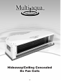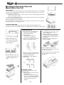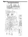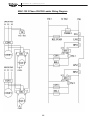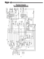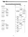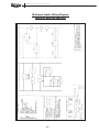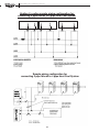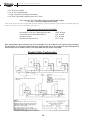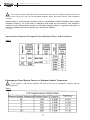
1
Quality Indoor Air
SM
Chilled Water
Air Conditioning Systems
Chillers • Water & DX Fan Coils (Hide Away, High Wall and Universal Mount)
1
January 2006
About Us
Setting new industry standards is what we do best.
At Multiaqua, our commitment to creating innovative air conditioning products has
made us one of the most respected organizations in the industry. From concept to market, Multiaqua takes a hands-on approach to ensure that each and every step meets
our stringent standards of quality, durability and dependability.
All Multiaqua products are designed with the future in mind. That’s why all air conditioning products are flexible, which makes it easy to adapt to virtually all kinds of building applications.
Whether it’s residential or commercial air conditioning needs, Multiaqua has the product to meet or exceed all expectations.
Manufacturing Excellence
Our belief in quality is more than just a practice, it is something we take great pride in.
Our quality management system is integrated with international quality requirements of
ISO 9002. That is why some of the biggest OEM names in the air conditioning industry use Multiaqua products in their units. In fact, Multiaqua chillers were part of air conditioning systems that won first place awards in the Quality Home Comfort Awards
Competition, which was created to honor the best in residential comfort system design
and application.
Our products are tested and certified to the UL, CE, ARL, ETL, UL1995, and ARI standards: the most respected and stringent in the world.
Experience The Future
At Multiaqua, we invite you to come experience the future of air conditioning and see
why more and more companies are discovering the new standard of air conditioning
excellence. And by combining cost effectiveness, innovation and quality, Multiaqua
will continue to provide air conditioning products that will be the most sought after in
the world.
2
Table of contents
About Us
Table of Contents
Brief Overview of Products
Features & Benefits
Page 2
Page 3
Page 4-5
Page 6
Mac Air-Cooled Chillers
Mac Product Specifications
Hi-Wall MHWW Chilled Water Fan Coil
MHWW Product Specifications
MHWW Heating Capacities
Mounting Instructions
Page 7
Page 8-12
Page 13
Page 14
Page 14
Page 15
Hi-Wall MHWX DX Fan Coil
MHWX DX Fan Coil Specifications
Mounting Instructions
Page 16
Page 17
Page 18
Hideaway/Ceiling Concealed Water Fan Coil
MHCCW Heating Capacities
MHNCCW Fan Coil Specifications
MCCW Chilled Water Fan Coil Specifications
Mounting Instructions
Page 19-20
Page 21
Page 22
Page 23
Page 24
Hideaway/Ceiling Concealed Dx Fan Coil
MCCX & MHCCX Dx Fan Coil Specifications
MHNCCX Fan Coil Specifications
Mounting Instructions
Page
Page
Page
page
25
26
27
28
Universal Mount CFFW & CFFZA Water Fan Coil
CFFW & CFFZA Chilled Water Fan Coil Specifications
CFFW & CFFZA Heating Capacities
Mounting Instructions
Page
Page
Page
Page
29
30
30
31
Universal Mount CFFC & FSFCA Dx Fan Coils
FSFCA Dx Fan Coil Specifications
CFFCA DX Fan Coil Specifications
Mounting Instructions
Multi Position Water Air Handler CWA2
General Specifications
Cooling Performance Data
Installation and Operation Manual
Page 32-34
Page 32-33
Page 34-35
Page 36
Page 37
Page 38
Page 39
Page 40-74
Limited Warranty Information and Registration
3
Page 75
Water Product Overview
MAC - Air Cooled Chiller
MACH-Air Cooled Heat Pump Chiller
• Self contained, air cooled R-22 chiller
• Copeland scroll compressor technology
• 3,4, 5 and 10 ton units
• Horizontal air discharge
• Up to 12.23 EER
• Stainless Steel pump included
• Heat pump available in 5 ton only
• 69 dbs sound level @ 5 feet
Page 7
Page 7
MHCCW Chilled Water w/Electric Heat
MHNCCW Chilled & Hot Water Fan Coil - 4 Pipe
Page 22
Page 21
• 12,000 - 36,000 btu/h
• Hideaway design for clean installation
• Powder painted galvanized steel
• Field reversible Coil--Left or Right hand
connections
• Heavy Gauge Metal Cabinet
• Dual manual air vents
• 42 - 48 dbs sound levels
• Electric heat
• 12,000 - 36,000 btu/h
• Hideaway design for clean installation
• Powder painted galvanized steel
• Double-field reversible Coil - Left or Right hand
connections
• Heavy Gauge Metal Cabinet
• Dual manual air vents
MCCW Water Hideaway - 2 Pipe
Hi-Wall MHWW Water Fan Coil
Page 23
Page 13
• 9,000 - 36,000 btu/h
• High wall mounting
• 42 - 48 dbs sound levels
• Attractive seamless appliance design
• Cleanable air filter included
• Infrared remote included
• Wired control option
•
•
•
•
•
12,000 - 60,000 btu/h
Hideaway design for clean installation
40 - 46 dbs sound levels
Removes equipment from conditioned space
Discharge may be split and ducted for small spaces
CFFZA & CFFW Universal Mount Water Fan Coil
Page 29
CWA2-Chilled Water Air Handler with Electric Heat
DX Air Handler with Electric Heat
Page 37
• 12,000 - 60,000 btu/h
• Floor, low wall or horizontal ceiling mount
• 42-48 dbs sound levels
• Attractive modular design
• Cleanable air filter included
• Factory supplied wired or wireless wall mounted
remote control
4
• 18,000 - 60,000 btu/h
• Up flow, horizontal left or
horizontal right
• Equipped with R 4.2 insulation
• 208 / 240 V / 1 phase/60 Hz
• Electric or hot water heat
• Electric heat
DX Product Overview
DX Fan Coils are compatible with R-22 Condensing Units
MHCCX DX Hideaway with Electric Heat
MHNCCX DX/Hot Water Hideaway Fan Coil
Page 27
Page 26
•
•
•
•
•
•
•
•
•
•
•
•
•
12,000 - 60,000 btu/h
Hideaway design for clean installation
40 - 46 dlbs sound levels
Discharge may be split and ducted for small spaces
Field Reversible DX coil
Electric heat
12,000 - 60,000 btu/h
Hideaway design for clean installation
40 - 46 dlbs sound levels
Removes equipment from conditioned space
Discharge may be split and ducted for small spaces
Hot water heating coil
Double field reversible coils - Left or Right hand
connections
MCCX Water Hideaway - Cooling Only
CFFCA & FSFCA Universal Mount DX Fan Coil
Page 34
Page 32
Page 26
•
•
•
•
•
• 12,000 - 60,000 btu/h
• Floor, low wall or horizontal ceiling mount
• 42-48 dbs sound levels
• Attractive modular design
• Cleanable air filter included
• Factory supplied wired or wireless wall mounted
remote control
• 13 Seer compatible DX Fan Coils equipped with
thermal expansion valves
12,000 - 60,000 btu/h
Hideaway design for clean installation
40 - 46 dbs sound levels
Removes equipment from conditioned space
Discharge may be split and ducted for small spaces
MHWX Hi-Wall DX Fan Coil
Page 16
• 9,000 - 36,000 btu/h
• High wall mounting
• 42 -48 dbs sound levels
• Attractive seamless appliance design
• Cleanable air filter included
• Infrared remote included
• Wired control option
5
Why buy a Multiaqua Chilled Water System?
Multiaqua Line of Chilled water
Air Conditioners Score a Perfect “10”
Chilled Water
A/C Unit
Forced Air CX
A/C Unit
1. Helps control the growth
of mold, mildew and fungus
1
0
2. More energy efficient thru
zoned comfort cooling
1
0
3. No refrigerant handling
1
0
4. No ductwork/Zero duct loss
1
0
5. Low installation costs
1
0
6. Can use gas household hot water for heat
1
0
7. No line length limitations
1
0
8. Easy to expand system, add capacity
or add indoor units
1
0
9. Unlimited tonnage with Single Phase Power
1
0
10. Quiet and reliable
1
1
10
1
SCORE
6
MAC & MACH Air-Cooled Chillers
(Cooling only and heat Pump Models)
Air-Cooled Chillers for Global Residential
and Light Commercial MicroClimates
7
Chilled Water Air Conditioning Systems
MAC Product Specifications
Chiller Dimensions
Clearance data relates to serviceability. Please check Local Building Department Regulations and Electrical Code Requirements.
MAC 036, 048, 060
Rear View
Front View
12” Clearance
12” Clearance
5’ Front
Clearance
Return
24” Clearance
Supply
Line Voltage
Control Voltage
These Models are designed to operate exclusively with R-22 in a self-contained, pre-charged refrigerant system. Do not
access the closed refrigerant system for any reason other than after-sale, after installation component replacement. Such
service is to be conducted by qualified service personnel only.
These specifications are subject to change without notice.
8
Chilled Water Air Conditioning Systems
MAC-120
Stated clearances for serviceability. Check
local building department regulations and
electrical code requirements.
Compressor
Heat Exchanger
Electrical Data
Max. Head Pressure
Max. Flow Rate
Min. Flow Rate
Supply Water Temp.
Return Water Temp.
Min. System Water Content
Expansion Tank Size*
Pump
Water Connections
MAC-036-1
Copeland Scroll K3
Brazed Plate
1-50/60-208/230 Volts
50 ft.
8.6 GPM
5.5 GPM1
44° F
54° F
25.0 Gals.
2.0 Gals.
1/2 Hp Centrifugal
Stainless Steel Pump Head
Silicon Carbide/Viton Seals
1” Supply, 11/4” Return
MAC-048-1
Copeland Scroll K3
Brazed Plate
1-50/60-208/230 Volts
50 ft.
11.5 GPM
6.5 GPM
44° F
54° F
25.0 Gals.
2.0 Gals.
1/2 Hp Centrifugal
Stainless Steel Pump Head
Silicon Carbide/Viton Seals
1” Supply, 11/4” Return
MAC-060-1
Copeland Scroll K3
Brazed Plate
1-50/60-208/230 Volts
50 ft.
14.4 GPM
9.0 GPM
44° F
54° F
25.0 Gals.
2.0 Gals.
1/2 Hp Centrifugal
Stainless Steel Pump Head
Silicon Carbide/Viton Seals
1” Supply, 11/4” Return
MAC-120
2 Copeland Scroll K3
Brazed Plate
208/230/1/50/60 Volts
28.8 GPM
18 GPM
45° F
55° F
50 Gals.
3% of System Total
Not Included
1.5” Supply, 1.5” Return
MACH 060-1
Copeland Scroll K3
Brazed Plate
1-50/60-208/230 Volts
50 ft.
14.4 GPM
9.0 GPM
44° F/130° F
54° F/120° F
25.0 Gals
2.0 Gals
1/2 Hp Centrifugal
Stainless Steel Pump Head
Silicon Carbide/Viton Seals
Supply, 11/4” Return
* Field Installed
Capacity / Watts / EER*
OD Temp. F
82
95
100
105
110
BTUH
36433
35062
33763
33186
32429
MAC-036-1
Watts
3170
3586
3782
3940
4180
EER
11.5
9.78
8.93
8.42
7.76
BTUH
48577
45210
44248
43286
41844
MAC-048-1
Watts
4147
4424
4624
4824
5305
EER
11.71
10.22
9.57
8.97
7.89
BTUH
63381
60712
59658
58653
58607
MAC-060-1
Watts
5182
5701
5945
6262
6582
EER
12.23
10.65
10.02
9.32
8.9
BTUH
119,911
114,840
112,543
110,629
110,517
MAC-120
Watts
EER
11,200 10.71
11,358 10.11
11,846
9.5
12,480
8.86
12,811
8.62
* Refrigerant system performance only, pump data not included.
The Multiaqua chiller is a self-contained air-cooled condenser, coupled with an insulated brazed plate heat
exchanger (evaporator). The system utilizes a scroll compressor to circulate refrigerant between the condenser
and heat exchanger. The refrigerant is metered into the heat exchanger with a thermostatic expansion valve.
Protecting the system are high and low pressure switches, as well as a pump flow switch.
Liquid solution (water and propylene glycol) is circulated through the heat exchanger by a chiller-mounted pump
(the pump liquid side is manufactured of stainless steel, with silicon carbide/Viton seals). The liquid solution flows
through the heat exchanger to the system supply piping, and on to the air handlers.
* Low ambient kit - IC M 325H(+)ICM175
Added upon request
These specifications are subject to change without notice.
9
Chilled Water Air Conditioning Systems
MAC Glycol Solution Data
The MAC Chiller must have a minimum of 10%
Propylene Glycol mix for water treatment and freeze protection.
MAC Glycol Solution Data
Propylene Glycol %
10%
20%
30%
40%
50%
Water Flow
x 1.020
x 1.028
x 1.036
x 1.048
x 1.057
Capacity
x 0.99
x 0.98
x 0.98
x 0.97
x 0.96
Min. Ambient Temperature
26° F
18° F
8° F
-7° F
-29° F
GPM Adjustment = 100% Capacity
x 1.01
x 1.03
x 1.07
x 1.11
x 1.16
Example: 30% glycol solution in MAC060-1
Maximum Flow Rate 12GPM x 1.036
System Capacity x 0.96
Use Propylene Glycol
Important
If the outside temperature is expected to fall below freezing (32F) in the area the MAC is to be installed;
the installer must take the following precautions. Failure to do so will void the warranty.
To not engage in cold ambient mitigation will result in the failure of components
such as the heat exchanger, piping, pump, etc., and property damage.
• Keep the system pump in a constant energized mode to keep constant circulation
of fluid
• Use a propylene glycol/water mix. The percentage amount of glycol recommended is
dependent on the expected ambient temperatures and the solution makeup recommendation of the glycol manufacturer. Refer to Glycol Solution Data Chart.
• A minimum of 10% Glycol is to be used at all times. Even in areas where there is no danger of freezing.
These specifications are subject to change without notice.
Warranty: One Year Parts, 5 Year Compressor, 5 Year Heat Exchanger, for North American
installations only. See Warranty Statement included with each Chiller for
Specifics and Exclusions.
Please Note:
For low ambient kit installed - Please add the suffix (L) after each MAC (Chiller part number).
10
Chilled Water Air Conditioning Systems
Guide Specifications
2. Air shall be discharged horizontally.
3. Fans shall be protected by coated steel wire
safety guards.
Air-Cooled Liquid Chiller
HVAC Guide Specifications
Size Range: 3, 4, 5 & 10 Tons
Multiaqua Model Number: MAC036, MAC048,
MAC060, MAC120
Part 1- General
1.01 SYSTEM DESCRIPTION
Air-cooled liquid chiller utilizing scroll compressor, low
sound fans, MAC036, MAC048, MAC060 include a
hydronic pump system.
1.02 QUALITY ASSURANCE
A. Unit shall be certified in accordance with U.L.
Standard 95, latest revision (U.S.A.).
B. Unit construction shall comply with ASHRAE 15
Safety Code, NEC, and ASME applicable codes
(U.S.A. codes).
C. Unit shall be manufactured in a facility registered
to ISO 9002, Manufacturing Quality Standard.
D. Unit shall be full load run tested at the factory.
1.03 DELIVERY, STORAGE, AND HANDLING
A. Unit controls shall be capable of withstanding
150 F storage temperatures in the control
compartment.
B. Unit shall be stored and handled per unit
manufacturer’s recommendations.
Part 2- Products
2.01 EQUIPMENT
A. General:
Factory assembled, air-cooled liquid chiller.
Contained within the unit cabinet shall be all
factory wiring, piping controls, refrigerant charge
(R-22), and special accessories required prior to
field start-up.
B. Unit Cabinet:
1. Cabinet shall be galvanized steel casing with a
baked polyester powder.
2. Cabinet shall be capable of withstanding 500hour salt spray test in accordance with the ASTM
(U.S.A.) standard.
C. Fans:
1. Condenser fans shall be direct-driven, 4-blade,
aluminum construction, and shall be statically
and dynamically balanced with inherent corrosion
resistance.
D. Compressors:
1. Fully hermetic scroll type compressors.
2. Direct Drive, 3500 rpm (60Hz) protected by either
line break device or discharge gas thermostat,
depending on motor, suction gas cooled motor.
3. External vibration isolation- rubber in sheat.
E. Cooler:
1. Cooler shall be rated for a refrigerant workingside pressure of 450 psig and shall be tested for
a maximum fluid-side pressure of 150 psig.
2. Shall be single-pass, ANSI type 316 stainless
steel, brazed plate construction.
3. Shell on MAC036, MAC048 & MAC060 shall be
insulated with _” closed cell, elastomeric foam
(ASTM518).
4. Shall incorporate one independent refrigerant
circuit.
F. Condenser:
1. Coil shall be air-cooled with integral subcooler,
and shall be constructed of aluminum fins
mechanically bonded to welded copper tubes.
2. Tubes shall be cleaned, dehydrated, and sealed.
3. Assembled condenser coils shall be leak tested
and pressure tested at 450 psig (3103 kPa).
G. Refrigeration Components:
Refrigerant circuit components shall include moisture
indicating sight glass, thermal expansion device, and
complete operating charge of both refrigerant R-22
and compressor oil.
H. Controls and Safeties:
1. Controls:
a. Unit controls shall include the following
minimum components:
b. Control transformer to serve all controllers,
relays, and control components.
c. Pump bypass timer.
d. Compressor recycle timer.
e. Optional low pressure
bypass timer for low ambient operation.
f. Optional fan cycling control for low ambient
operation.
g. Flow switch.
11
Chilled Water Air Conditioning Systems
h. Leaving water temperature thermostat with
thermistor installed to measure cooler leaving
fluid temperatures.
2. Unit controls shall include the following functions.
a. Capacity control based on leaving chilled fluid
temperature. Temperature set point accuracy
+ - 1.0 F.
b. Chilled water pump start/stop control.
3. Safeties:
a. Unit shall be equipped with thermistors and all
necessary components in conjunction with the
control system to provide the unit with the
following protectants:
1) Low refrigerant pressure.
2) Low chilled fluid temperature.
3) Thermal overload.
4) High refrigerant
pressure.
b. Condenser fan and factory pump motors shall
have internal thermal protection.
I. Operating Characteristics:
1. Unit shall be capable of starting and running at
outdoor ambient temperatures from 0 F to 120 F
with optional Low Ambient Kit.
2. Unit shall be capable of starting up with 95 F (35
C) entering fluid temperature to the cooler.
J. Motors:
Condenser fan motors shall be totally enclosed single
speed, with permanently lubricated sleeve bearings
and Class F insulation.
being serviced without disturbing piping
connections.
a. Pump casing shall be of stainless steel.
b. The impeller shall be of stainless steel type,
dynamically balanced and screwed onto the
shaft.
c. The liquid cavity shall be sealed off at the
motor shaft by an internally flushed mechanical
seal with silicon carbide face and viton seal
ring.
d. Pump shall be rated for 80 psig working
pressure.
e. The pump case shall have drain ports.
f. Motors shall be totally enclosed 1-phase type
with permanentely lubricated sleeve bearings.
Each pump shall be factory tested per
Hydraulic Institute Standards.
g. Please note that 1/2 HP pump is included
only on our 3, 4 and 5 ton models. 10 ton
model does not included pump.
3. Brass body strainer with 20 mesh screen and
blow down supplied in cabinet as field
installable accessory.
M. Special Features:
1. Low-Ambient Operation:
a.Unit shall be capable of starting and running at
outdoor ambient temperatures down to –20 F
(-29 C) with the addition of antifreeze in the
cooler circuit and field or factory-installed low
ambient kit.
K. Electrical Requirements:
1. Unit primary electrical power supply shall enter
the unit at a single location.
2. Primary electrical power supply shall be rated to
withstand 120 F (50 C) operating ambient.
3. Unit shall operate on 1-phase or 3-phase power
at the voltage shown in the equipment schedule.
4. Control points shall be accessed through terminal
block.
5. Unit shall be shipped with factory control and
power wiring installed.
L. Hydronic System:
1. Field pipe connections shall be brass NPT and
shall be extended to the outside of the unit
chassis.
2. Pumps shall be single stage design, for
installation in horizontal position and capable of
12
Hi-Wall MHWW Chilled
Water Fan Coil
with Wireless Remote Control
Wired Remote Control Option
13
Chilled Water Air Conditioning Systems
1
1
Capacity listed at 44°F L.W.T., 55ºF E.W.T.
MHWW Heating Capacities High Wall Water
MHWW-09 Htg. Capacity @ 1.8 GPM
EAT
MHWW-12 Htg. Capacity @ 2.4 GPM
100 EWT 110 EWT 120 EWT 130 EWT
100 EWT 110 EWT 120 EWT 130 EWT
EAT
50
10542
12690
14847
17012
50
12933
15561
18198
20844
60
8446
10587
12738
14897
60
10358
12978
15610
18249
70
6346
8481
10626
12779
70
7780
10393
13018
15652
80
4243
6371
8511
10660
80
5199
7806
10425
13053
MHWW-18 Htg. Capacity @ 3.6 GPM
EAT
MHWW-24 Htg. Capacity @ 4.8 GPM
100 EWT 110 EWT 120 EWT 130 EWT
EAT
100 EWT 110 EWT 120 EWT 130 EWT
50
19495
23445
27408
31381
50
26686
32086
37499
42924
60
15617
19557
23511
27477
60
21367
26756
32159
37576
70
11735
15665
19611
23569
70
16043
21421
26816
32224
80
7848
11770
15708
19659
80
10715
16083
21468
26868
MHWW-36 Htg. Capacity @ 7.2 GPM
EAT
100 EWT 110 EWT 120 EWT 130 EWT
50
38482
46254
54043
61845
60
30806
38565
46341
54133
70
23125
30871
38636
46418
80
15438
23172
30927
38699
14
Chilled Water Air Conditioning Systems
Mounting Instructions Hi-Wall Water Fan Coil
Select the location of the indoor unit with the following consideration:
1.
2.
3.
4.
The front of the air inlet and outlet shall be free from any obstruction. The outlet air should flow out freely.
The wall where the unit is to be mounted should be stiff enough not to resonate and produce noise.
Ensure the clearance on every side of the indoor unit to conform to figure 1.
From floor, the height should e more than eye level.
Caution: Avoid installing the unit in direct sunlight.
Maintenance & Servicing Space
Air Flow Direction
Mounting Plate Installation
1. After a suitable place for installation has been selected, place the mounting plate horizontally on the
wall. Make sure the alignment is horizontal. Use a plumb line, if available.
2. Referring to the figure below, mark the location for the wall plugs and the hole for the pipings.
Plan dimension for mounting plate installation
15
Hi-Wall MHWX
DX FAN COIL
With Wired Remote Control Option
Chilled Water Air Conditioning Systems
MHWX Dx Fan Coil Specifications
Model
Description
Cooling Capacity (BTUH) Nominal
Airflow (CFM) @ High-Speed
Motor HP - Qty.
Supply Voltage
MHWX-09
MHWX-12
MHWX-18
MHWX-24
MHWX-36
9000 BTUH
12000 BTUH
18000 BTUH
24000 BTUH
36000 BTUH
208/230V-1-50/60 208/230V-1-50/60 208/230V-1-50/60 208/230V-1-50/60 208/230V-1-50/60
9,000
12,000
270
1/50-1
18,000
24,000
36,000
330
480
600
850
1/50-1
1/20-1
1/20-1
1/12-1
1
Phase - 50/60 Hz - 208/230 VAC
Motor Power Consumption (Watts)
16
16
35
35
60
Blower Size - Qty.
3.9”x27.4”- 1 3.8”x31.7”-1 4.0”x35.4”-1 4.1”x35.4”-1 4.2”x22.6”-2
Coil Type
Hydrophilic Plate Fin, Plain Tube
Hydrophilic Plate Fin, Grooved Tube
No. of Rows - FPI
2 - 20
2 - 14
2 - 16
3 - 17
3 - 18
2
Coil Face Area (Ft. )
1.67
1.94
2.46
2.46
3.54
Liquid Line - Flare (Inches)
1/4
1/4
5/16
3/8
3/8
Suction Line - Flare (Inches)
3/8
3/8
1/2
5/8
5/8
Drain Connection (Inches)
1/2
1/2
3/4
3/4
3/4
Dimensions (Inches) Width
34.6
39.0
46.1
46.1
57.1
Height
11.7
12.0
14.2
14.2
14.4
Depth
7.1
7.1
8.1
8.1
8.5
Approx. Weight in Lb.’s
20.0
22.0
35.6
37.4
54.0
Sound Data (db)
34/38/42
34/38/42
40/42/45
40/42/45
38/44/48
Air Filter
Washable
Fan Speed
3 Speed plus Auto Fan Function
* Please add (-13) for 13 Seer equipment.
* Cooling based on 75% Sensible, 25% Latent, 80°D.B./67°W.B.
17
Chilled Water Air Conditioning Systems
Mounting Instructions Hi-Wall DX Fan Coil
Select the location of the indoor unit with the following consideration:
1.
2.
3.
4.
The front of the air inlet and outlet shall be free from any obstruction. The outlet air should flow out freely.
The wall where the unit is to be mounted should be stiff enough not to resonate and produce noise.
Ensure the clearance on every side of the indoor unit to conform to figure 1.
From floor, the height should e more than eye level.
Caution: Avoid installing the unit from direct sunlight.
Maintenance & Servicing Space
Air Flow Direction
Mounting Plate Installation
1. After a suitable place for installation has been selected, place the mounting plate horizontally on the
wall. Make sure the alignment is horizontal. Use a plumb line, if available.
2. Referring to the figure below, mark the location for the wall plugs and the hole for the pipings.
Plan dimension for mounting plate installation
18
Hideaway Fan
Coil Section
* Please note that all Hideaway Fan Coils come
equipped with a 24V Transformer & Relay
19
Hideaway/Ceiling Concealed
Water Fan Coils
20
Chilled Water Air Conditioning Systems
21
Chilled Water Air Conditioning Systems
22
Chilled Water Air Conditioning Systems
Description
“1 Ton”
208/230V-1-50/60
“1.5 Ton”
208/230V-1-50/60
“2 Ton”
208/230V-1-50/60
1/15-3
1/15-3
1/8-3
“3 Ton”
208/230V-1-50/60
“4 Ton”
208/230V-1-50/60
“5 Ton”
208/230V-1-50/60
1
Speeds
1/4-3
1/2-3
1/2-3
1
Capacity listed at 44°F L.W.T., 55ºF E.W.T.
Based upon .15 static discharge
MCCW Heating Capacities Hideaway/Ceiling Concealed
MCCW04 Heating Capacity (BTUH) at 2.4 GPM
EAT
MCCW12 Heating Capacity (BTUH) at 7.2 GPM
100 EWT 110 EWT 120 EWT 130 EWT 140 EWT 150 EWT 160 EWT 170 EWT 180 EWT 190 EWT 200 EWT
EAT
100 EWT 110 EWT 120 EWT 130 EWT 140 EWT 150 EWT 160 EWT 170 EWT 180 EWT 190 EWT 200 EWT
50
13998
16816
19645
22483
25328
28180
31036
33895
36757
39621
42486
50
40270
48345
56437
64542
72657
80780
88908
97040
105173
113308
121442
60
11243
14052
16873
19705
22544
25390
28241
31096
33955
36815
39677
60
32289
40351
48432
56527
64633
72747
80869
88994
97123
105253
113383
70
8483
11284
14099
16924
19757
22598
25444
28295
31150
34007
36866
70
24302
32352
40422
48507
56604
64711
72826
80946
89069
97194
105321
80
5720
8514
11321
14140
16968
19803
22645
25492
28343
31197
34053
80
16309
24348
32407
40483
48572
56672
64780
72894
81012
89134
97257
MCCW06 Heating Capacity (BTUH) at 3.6 GPM
EAT
MCCW16 Heating Capacity (BTUH) at 9.6 GPM
100 EWT 110 EWT 120 EWT 130 EWT 140 EWT 150 EWT 160 EWT 170 EWT 180 EWT 190 EWT 200 EWT
EAT
100 EWT 110 EWT 120 EWT 130 EWT 140 EWT 150 EWT 160 EWT 170 EWT 180 EWT 190 EWT 200 EWT
50
19785
23765
27756
31754
35759
39769
43783
47799
51818
55837
59858
50
52762
63322
73915
84535
95176
105833
116503
127183
137869
148559
159252
60
15859
19832
23816
27809
31808
35813
39822
43835
47850
51867
55884
60
42381
52917
63488
74088
84711
95352
106008
116675
127350
138031
148715
70
11931
15897
19874
23861
27855
31855
35860
39869
43881
47895
51910
70
31990
42502
53052
63633
74239
84865
95507
106162
116826
127498
138173
80
8000
11958
15736
19910
23900
27895
31896
35902
39910
43921
47934
80
21588
32077
42607
53169
63759
74371
85000
95643
106297
116959
127627
MCCW08 Heating Capacity (BTUH) at 4.8 GPM
EAT
MCCW20 Heating Capacity (BTUH) at 12 GPM
100 EWT 110 EWT 120 EWT 130 EWT 140 EWT 150 EWT 160 EWT 170 EWT 180 EWT 190 EWT 200 EWT
EAT
100 EWT 110 EWT 120 EWT 130 EWT 140 EWT 150 EWT 160 EWT 170 EWT 180 EWT 190 EWT 200 EWT
50
25437
30560
35697
40846
46004
51170
56341
61516
66694
71873
77054
50
60476
72588
84724
96880
109050
121232
133422
145617
157816
170017
182218
60
20396
25508
30635
35775
40925
46083
51248
56418
61591
66766
71943
60
48498
60591
72711
84852
97009
109179
121358
133545
145736
157930
170125
70
15351
20451
25569
30700
35843
40994
46153
51317
56485
61656
66829
70
36513
48588
60692
72818
84963
97121
109291
121469
133652
145840
158029
80
10301
15391
20499
25622
30758
35902
41055
46214
51377
56544
61714
80
24521
36579
48667
60779
72911
85059
97219
109388
121565
133746
145929
23
Chilled Water Air Conditioning Systems
Mounting
Instructions
Concealed Water
Fan Coil
(11.73) (7.44)
(56.38) (51.85) (50.20)
A. GENERAL
1a. INSTALLATION - This product is
designed and manufactured to permit
installation in accordance with National
Codes. It is the installer’s responsibility to
install the product in accordance with
National Codes and / or prevailing local
codes and regulation.
1B. PRE - INSTALLATION CHECK - POINTS
- Before attempting any installation, the
following points should be considered.
- Structural strength of supporting
members.
- Clearances and provision for servicing.
- Power supply and wiring.
- Drain facility and connections.
2a. Location - These units are designed to
be installed in horizontal position above
a dropped ceiling. The location of the
unit should be based on thorough
consideration of the PRE INSTALLATION CHECK POINTS.
B. INSTALLATION
1. Before locating the unit on the drop
ceiling, make sure that the strength of the
ceiling and beams is adequate at the
point to support the weight involved. This
is very important and installer’s
responsibility. The list on the right shows
approximate weight of unit.
24
Hideaway/Ceiling Concealed
Dx Fan Coils
25
Chilled Water Air Conditioning Systems
Description
“1 Ton”
208/230V-1-50/60
“1.5 Ton”
208/230V-1-50/60
“2 Ton”
208/230V-1-50/60
1-50/60-208/230 Volt
9.72
* Please add (-13) for 13 Seer equipment.
* Cooling based on 75% Sensible, 25% Latent, 80°D.B./67°W.B.
26
“3 Ton”
208/230V-1-50/60
“4 Ton”
208/230V-1-50/60
“5 Ton”
208/230V-1-50/60
Chilled Water Air Conditioning Systems
27
Chilled Water Air Conditioning Systems
Mounting
Instructions
Concealed DX
Fan Coil
CCX04
CCX06
REFRIGERANT IN
CCX08
CCX12
CCX16
CCX20
REFRIGERANT OUT
A. GENERAL
1a. INSTALLATION - This product is
designed and manufactured to permit
installation in accordance with National
Codes. It is the installer’s responsibility to
install the product in accordance with
National Codes and / or prevailing local
codes and regulation.
1B. PRE - INSTALLATION CHECK - POINTS
- Before attempting any installation, the
following points should be considered.
CCX04-20
- Structural strength of supporting
members.
- Clearances and provision for servicing.
- Power supply and wiring.
- Drain facility and connections.
2a. Location - These units are designed to
be installed in horizontal position above
a dropped ceiling. The location of the
unit should be based on thorough
consideration of the PRE INSTALLATION CHECK POINTS.
B. INSTALLATION
1. Before locating the unit on the drop
ceiling, make sure that the strength of the
ceiling and beams is adequate at the
point to support the weight involved. This
is very important and installer’s
responsibility. The list on the right shows
approximate weight of unit.
CCX04
CCX06
CCX08
CCX12
CCX16
CCX20
28
Universal Mount
CFFWA & CFFZA Water Fan Coil
Available with Wired or Wireless
Remote Control Option
29
Chilled Water Air Conditioning Systems
(CFFWA & CFFZA) Chilled Water Fan Coil Specifications
Description
“1 Ton”
220V-1-50/60
“1.5 Ton”
220V-1-50/60
“2 Ton”
220V-1-50/60
“3 Ton”
220V-1-50/60
1/8-3
1/8-3, 1/20-3
“4 Ton”
220V-1-50/60
“5 Ton”
220V-1-50/60
1
Speeds
1/15-3
1/15-3
1/8-3
1/8-3
1-50/60-208/230 Volt
1
Capacity listed at 44°F L.W.T., 55ºF E.W.T.
(CFFW & CFFZA) Heating Capacities Universal Mount
CFFW04 Heating Capacity(BTUH) at 2.4 GPM
EAT
CFFW06 Heating Capacity(BTUH) at 3.6 GPM
100 EWT 110 EWT 120 EWT 130 EWT
EAT
100 EWT 110 EWT 120 EWT 130 EWT
50
14024
16846
19680
22524
50
19889
23890
27901
31920
60
11264
14078
16905
19741
60
15946
19939
23943
27956
70
8500
11307
14126
16956
70
12000
15985
19982
23989
80
5733
8531
11344
14168
80
8050
12028
16019
20020
CFFW08 Heating Capacity(BTUH) at 4.8 GPM
EAT
CFFW12 Heating Capacity(BTUH) at 7.3 GPM
100 EWT 110 EWT 120 EWT 130 EWT
EAT
100 EWT 110 EWT 120 EWT 130 EWT
50
25846
31052
36273
41506
50
41728
50118
58526
66948
60
20725
25919
31130
35354
60
33442
41818
50213
58624
70
15598
20782
25983
31198
70
25149
33511
41895
50295
80
10468
15640
20832
26038
80
16850
25200
33572
41962
CFFW16 Heating Capacity(BTUH) at 9.6 GPM
EAT
CFFW20 Heating Capacity(BTUH) at 12 GPM
EAT
100 EWT 110 EWT 120 EWT 130 EWT
100 EWT 110 EWT 120 EWT 130 EWT
50
54255
65172
76116
87084
50
59779
71859
83974
96118
60
43499
54394
65320
76270
60
47899
59951
72042
84164
70
32734
43608
54515
65448
70
36008
48034
60100
72201
80
21959
32813
43702
54620
80
24107
36107
48151
60231
Note: CFFWA-Equipped w/wired remote: CFFZA-Equipped w/wired & wireless remote
30
Chilled Water Air Conditioning Systems
Mounting Instructions-Universal
Mount Water Fan Coil
INITIAL CHECK
1) The carton should not be removed from unit until reaching final location to avoid damage.
2) Inspect unit for shipping damage and file a claim with the transport agency if necessary.
3) Check field electrical works:
a) Proper size of fuses and wire, correct wiring connections and grounding as specified
by the local electrical codes.
b) Also check supply voltage, which must be within the limits shown on the nameplate.
4) Check for a proper condensate flow.
5) Be sure piping insulation is adequate.
6) Confirm there are no obstructions to air flow for indoor and outdoor units. Also check for
sufficient clearances for servicing the unit.
LOCATION & MOUNTING
1) The unit should be installed for horizontal and vertical discharge application only.
2) Select position for unit and define direction of refrigerant pipe, drain pipe and electrical wire.
3) Prepare mounting bolt for
mounting unit under ceiling
or on a wall at the distance
defined in figure 1.
CONDENSATE DRAIN
1) Be sure the unit is reasonably level
and pitched toward the drain to
ensure proper drainage.
2) Piping material
a) Soft Vinyl Chloride pipe
b) Hard Vinyl Chloride (PVC)
3) Connect the soft/hard Vinyl Chloride
pipe to the coupling. see fig 4
Fig. 4
4) Remove unit from carton and
carefully place the unit to the
position and tighten the 4
bolts.
4) The indoor unit uses gravity to drain:
therefore the piping outside the unit
should slope downward.
5) IMPORTANT: - avoid draining as
shown in Fig 5
2) The liquid line and suction line should
run according to piping design as
shown in figure 6.
3) Brazing should be performed with a
constant purge of nitrogen through
the piping. This is to keep inside of
tubing clean.
4) Insulate suction line adequately to
prevent sweating.
Note: The piping may also be run
around the rear of the unit so as to exit
from the left of the unit
5) Use two spanners to connect the flare
nut connection to the indoor unit.
See figure 7.
Fig. 5
Fig. 7
REFRIGERANT PIPING
1) Connections to the indoor unit are
flared connection.
i) Make flared joints for both suction
and liquid lines.
ii) Ensure tube and fitting are in line
with one another before tightening
nut to allow concentric sealing of
tube onto fitting to prevent
leakage.
31
Universal Mount
FSFCA Dx Fan Coil
Available with Wired or Wireless
Remote Control Option
32
Chilled Water Air Conditioning Systems
33
Universal Mount
CFFCA Dx Fan Coil
With Wired Remote Control
34
Chilled Water Air Conditioning Systems
CFFC Dx Fan Coil Specifications
Model
Description
Cooling Capacity (BTUH) Nominal
Airflow (CFM) @ High-Speed
Motor HP - Qty.
Supply Voltage
Motor Power Consumption (Watts)
Blower Size - Qty.
Coil Type
No. of Rows - FPI
Coil Face Area (Ft.2)
Liquid Line - Sweat (Inches)
Suction Line - Sweat (Inches)
Drain Connection (Inches)
Dimensions (Inches) Width
Height
Depth
Approx. Weight in Lb.’s
CFFCA-04
FCFCA
12,000
436
1/15-1
124
6” x 8”- 2
2 - 13
1.67
3/8
1/2
1/2
40.31
25.27
9.01
79.37
CFFCA-06
FCFCA
CFFCA-08
CFFCA-12
CFFCA-16
CFFCA-20
18,000
24,000
36,000
48,000
58,400
520
650
735
1360
1/15-1
1/8-1
1/8-1,1/20-1
1/8-2
1-50/60-208/230 Volt
124
183
297
366
6” x 8”- 2
7” x 8”- 2
7” x 8”- 2
7” x 8”- 4
Aluminum Plate Fin, 3/8” Grooved Tube Copper
3 - 13
4 - 13
3 - 13
3 - 14
1.67
1.67
2.78
4.17
3/8
3/8
3/8
3/8
5/8
5/8
5/8
3/4
1/2
1/2
1/2
1/2
40.31
40.31
52.13
75.78
25.27
25.27
25.27
25.27
9.01
9.01
9.01
9.01
83.77
88.18
116.84
158.73
* Please add (-13) for 13 Seer equipment.
* Cooling based on 75% Sensible, 25% Latent, 80°D.B./67°W.B.
35
1335
1/8-2
366
7” x 8”- 4
3 - 14
4.17
3/8
3/4
1/2
75.78
25.27
9.01
163.14
Chilled Water Air Conditioning Systems
Mounting InstructionsUniversal Mount DX Fan Coil
INITIAL CHECK
1) The carton should not be removed from unit until reaching final location to avoid damage.
2) Inspect unit for shipping damage and file a claim with the transport agency if necessary.
3) Check field electrical works:
a) Proper size of fuses and wire, correct wiring connections and grounding as specified
by the local electrical codes.
b) Also check supply voltage, which must be within the limits shown on the nameplate.
4) Check for a proper condensate flow.
5) Be sure piping insulation is adequate.
6) Confirm there are no obstructions to air flow for indoor and outdoor units. Also check for
sufficient clearances for servicing the unit.
LOCATION & MOUNTING
1) The unit should be installed for horizontal and vertical discharge application only.
2) Select position for unit and define direction of refrigerant pipe, drain pipe and electrical wire.
3) Prepare mounting bolt for
mounting unit under ceiling
or on a wall at the distance
defined in figure 1.
CONDENSATE DRAIN
1) Be sure the unit is reasonably level
and pitched toward the drain to
ensure proper drainage.
2) Piping material
a) Soft Vinyl Chloride pipe
b) Hard Vinyl Chloride (PVC)
3) Connect the soft/hard Vinyl Chloride
pipe to the coupling. see fig 4
Fig. 4
4) Remove unit from carton and
carefully place the unit to the
position and tighten the 4
bolts.
4) The indoor unit uses gravity to drain:
therefore the piping outside the unit
should slope downward.
5) IMPORTANT: - avoid draining as
shown in Fig 5
2) The liquid line and suction line should
run according to piping design as
shown in figure 6.
3) Brazing should be performed with a
constant purge of nitrogen through
the piping. This is to keep inside of
tubing clean.
4) Insulate suction line adequately to
prevent sweating.
Note: The piping may also be run
around the rear of the unit so as to exit
from the left of the unit
5) Use two spanners to connect the flare
nut connection to the indoor unit.
See figure 7.
Fig. 5
Fig. 7
REFRIGERANT PIPING
1) Connections to the indoor unit are
flared connection.
i) Make flared joints for both suction
and liquid lines.
ii) Ensure tube and fitting are in line
with one another before tightening
nut to allow concentric sealing of
tube onto fitting to prevent
leakage.
36
CWA2 Multi Position Water
Air Handler
37
Chilled Water Air Conditioning Systems
Air Handler / Chilled Water / Electric
CWA2
SERIES
Multiposition Design With Chilled Water Coil (0-20 KW)
(Upflow/Horizontal Left or Horizontal Right *)
TM
F
Description:
E
G
B
A
B
AIR OT T
INL OM
ET
C
D
Physical Dimensions
Model No.
A
24CWA2-XX
The CWA2-XX chilled water air handler with
electric heat series is designed for multiposition applications in closet, attic or
basement installations. The 24CWA2-XX
unit handles up to 800 CFM of air movement, 1.5 to 2.0 tons of cooling and up to
10 KW of electric heat. The 36CWA2-XX unit
handles up to 1200 CFM of air movement,
up to 3.0 tons of cooling and up to 15KW of
electric heat. The 48CWA2-XX unit handles
up to 1750 CFM of air movement, 3.0 to 4.0
ton’s of cooling and up to 20 KW of electric
heat.The 60CWA2-XX unit will move up to
2100 CFM of air, 3 to 5 tons of cooling and
up to 20KW of electric heat. For cooling
requirements, these units are designed with
2-pipe chilled water a-coils. These units are
UL & ULc listed (Approved for Canada).
B
C
D
E
F
17 /2
21
15
17 /2
16
12 /8
393/4
211/2
25
191/4
221/4
195/8
171/4
493/4
1
1
G
5
36CWA2-XX
48CWA2-XX
60CWA2-XX
Note: “-XX” indicates electric heat (KW) size.
Standard Features:
I Upflow, horizontal right to left and (*) easily field converted to horizontal
left to right airflow without additional parts.
I Drain pans are plastic, thus non-rusting.
I Drain pans have primary and secondary drains for either Left or Right
hand connections.
I Pre-painted (Designer Grey) front & top is the same high quality finish
found on refrigerators today. Cabinet durability is ensured by using a heavy
Ga. galvanized steel.
I All units are equipped with Time Delay Relay, factory installed (standard).
I All units have R4.2 Insulation, which meets Florida requirements (standard).
I All units include a 1-inch throwaway filter (standard).
I All units are 208/240V / 1 Phase / 60 HZ.
I All units are shipped with a 208/240V / 40VA transformer.
I All units are suitable for 0 inch clearance to combustible materials.
I Units are not suitable for Counterflow / Downflow applications.
I Blower assembly slides out for easy maintenance.
I Chilled water coil connections are swaged and then factory sealed with
copper caps to maintain a nitrogen holding charge.
Optional Extra:
I Factory installed Circuit Breaker on 10 KW and below models.
38
Chilled Water Air Conditioning Systems
General Specifications:
General Specifications:
Model No.
Cooling
Capacity
Blower
Nominal SCFM
@.2ESP w/coil
24CWA2-XX
1.5 - 2 Tons
KW
-45
900
0-10
36CWA2-XX
2.5 - 3 Tons
-34
1200
48CWA2-XX
3 - 4 Tons
-55
1700
60CWA2-XX
5 Tons
-51
2100
0-20
Filters:
Model No.
Cooling
Capacity
Blower
0-15
24CWA2-XX
1.5 - 2 Tons
0-20
36CWA2-XX
2.5 - 3 Tons
48CWA2-XX
60CWA2-XX
Shipping Data:
Model No.
Filter Size
24CWA2-XX
16x20x1
36CWA2-XX
20x20x1
48CWA2-XX
20x25x1
60CWA2-XX
20x25x1
Model
No.
Max.
Shp. Wt.
w/coil
Qty. Per
Truck
Load
118
145
170
180
192
192
144
144
24CWA2-XX
36CWA2-XX
48CWA2-XX
60CWA2-XX
Nominal SCFM
@.2ESP w/coil
KW
-45
900
0-10
-34
1200
0-15
3 - 4 Tons
-55
1700
0-20
5 Tons
-51
2100
0-20
Blower Data:
Airflow
Tonnage
Model No.
Motor @230V
1 Ph 60 Hz
DD
Blower
3 Spd.
Motor
Range
HP
FLA
Wheel
(Tons)
Duty
.1
.2
H(2.0)
Cool
950
900
1.5 - 2.0
1/4
1.7
10x6
M(1.5)
L
Cool
Heat
850
700
800
660
24CWA2-00
24CWA2-05
24CWA2-08
SCFM
24CWA2-10
Blower Data:
Airflow
Tonnage
Model No.
24CWA2-00
24CWA2-05
24CWA2-08
24CWA2-10
36CWA2-00
36CWA2-05
36CWA2-08
36CWA2-10
36CWA2-15
48CWA2-00
48CWA2-05
48CWA2-08
48CWA2-10
48CWA2-15
48CWA2-20
60CWA2-00
60CWA2-05
60CWA2-08
60CWA2-10
60CWA2-15
60CWA2-20
Shipping Data:
Motor @230V
1 Ph 60 Hz
DD
Blower
3 Spd.
Motor
Range
HP
FLA
Wheel
(Tons)
Duty
.1
.2
.3
.4
.5
1.5 - 2.0
1/4
1.7
10x6
H(2.0)
M(1.5)
L
Cool
Cool
Heat
950
850
700
900
800
660
850
740
610
790
680
550
720
610
480
2.5 - 3.0
1/3
2.8
10x7
H(3.0)
M(2.5)
L
Cool
Cool
Heat
1250
1070
900
1200
1020
870
1120
970
840
1060
920
790
1000
860
720
3.0 - 3.5
1/3
3.1
10x8
H(4.0)
M(3.5)
L
Cool
Cool
Heat
1850
1750
1150
1700
1650
1060
1650
1450
1000
1500
1330
920
1410
1180
810
3.0 - 4.0
1/3
3.1
10x8
H(5.0)
M(4.0)
L
Cool
Cool
Heat
2160
2110
2000
2100
1980
1860
2000
1810
1670
1940
1750
1340
1880
1650
1200
SCFM vs. ESP (1) (2)
Model
No.
24CWA2-XX
36CWA2-XX
48CWA2-XX
60CWA2-XX
Cooling Performance Data:
Notes: (1) Based upon unit w/nominal tonnage dry coil and filter installed.
(2) Use .96 as approximate SCFM correction factor for wet coil.
39
11,500
9,200
12,200
9,150
12,520
10,016
13,400
10,050
13,150
10,520
14,140
10,605
15,730
12,584
16,600
12,450
17,000
13,600
18,100
13,575
17,900
14,320
19,140
14,355
15,700
12,560
16,500
12,375
17,300
13,840
18,400
13,800
18,300
14,640
19,650
14,737
19,800
15,840
20,900
15,675
21,600
17,280
22,900
17,175
22,900
18,320
24,400
18,300
24,800
19,840
26,000
19,500
27,300
21,840
29,000
21,750
29,000
23,200
31,000
23,250
29,600
23,680
31,150
23,362
31,500
25,200
33,300
24,975
31,900
25,520
35,000
26,250
32,000
25,600
33,400
25,050
34,500
27,600
36,250
27,187
36,400
29,120
38,500
28,875
37,700
30,160
39,500
29,625
40,500
32,400
42,700
32,025
42,600
34,080
45,100
33,825
40,400
32,320
42,500
31,875
43,100
34,480
45,600
34,200
45,200
36,160
48,100
36,075
47,700
38,160
50,000
37,500
52,100
41,680
55,100
41,325
55,200
44,160
58,700
44,025
Max.
Shp. Wt.
w/coil
Qty. Per
Truck
Load
118
145
170
180
192
192
144
144
MAC Chiller
Installation and
Operation Manual
TABLE OF CONTENTS
...............................................................................................................................................PAGE
Table of Contents.......................................................................................................................40
Multiaqua Chiller Manual Introduction......................................................................................41
System Description & Sequence of Operation.........................................................................42
Electrical & Physical Data ....................................................................................................43-44
Electrical Schematic MAC-120 (Single Phase 208/230 VAC) ..................................................45
MAC-120 3 Phase 208/230 Ladder Wiring Diagram ................................................................46
Electrical Schematic MAC-120 3 Phase 380/460 VAC.............................................................47
MAC-120 3 Phase 380/460 Ladder Wiring Diagram ................................................................48
Multiaqua Ladder Wiring Diagram (MAC036, MAC048, MAC060) ..........................................49
Electrical Schematic (Single Phase 208/230 VAC - MAC036, MAC048, MAC060).................50
Electrical Schematic (3 Phase 208/230 VAC - MAC036, MAC048, MAC060).........................51
Electrical Schematic (3 Phase 380/460 VAC - MAC036, MAC048, MAC060).........................52
Description of Electrical Controls........................................................................................53-55
Chiller Controls Sequence of Operation..............................................................................55,56
Refrigeration System Operations ..............................................................................................56
Description of Refrigeration Components...........................................................................56,57
Condenser Coil ..........................................................................................................................57
Piping System Components.................................................................................................58,59
Composite Piping Layout and Design ......................................................................................60
Heating & Cooling Sample Piping Configuration
for Connecting 2 Pipe Fan Coil to 4 Pipe Heat Cool System..................................................61
Sample Piping Configuration for Connecting
2 Pipe Fancoil to 4 Pipe heat Cool System .............................................................................61
Chiller System Data ...................................................................................................................62
Composite Pipe performance Data ..........................................................................................63
Pipe Fitting Performance Data..................................................................................................63
Multiaqua Air handler Pipe Performance Data ...................................................................64-69
Banked Chiller Configuration ....................................................................................................69
Installation Notes..................................................................................................................70-74
40
Chilled Water Air Conditioning Systems
Multiaqua Chiller Manual
The Multiaqua Chiller System is the only air conditioning/refrigeration system of it’s kind in the world today
offering the degree of application flexibility described in the following Manual.
The Multiaqua Chiller System is not only unique in its application flexibility; it is unique in superior quality,
rated capacity, and rugged durability. When installed in accordance with these instructions the system will
deliver years of trouble free service.
Proper equipment sizing, piping design and installation are critical to the performance of the chiller. This
manual is meant to be a “how to” introduction to piping and installing the Multiaqua Chiller System.
!
RECOGNIZE THIS SYMBOL AS AN INDICATION OF IMPORTANT SAFETY OR INSTALLATION
RELATED INFORMATION.
Pressure loss information for a Composite Piping system has been used in preparing this manual. Web site
information addresses are supplied throughout this manual for piping and accessory information. The
plumbing industry also has pressure drop information on ferrous and copper piping systems, which will
vary from the composite pipe system outlined in this manual. Composite pipe is the recommended pipe for
Multiaqua Chiller System installations, however existing piping systems can be adapted to the system.
The following sections will describe each component, and how it functions within the system. Installation information
is supplied where appropriate. The piping design section will explain the design and layout out of the piping system
from a “how to” perspective. Following the examples provided will enable the installer to determine the correct pipe
and accessory sizing, as well as equipment location. It is important to know before installation if the proposed system
will operate correctly, and doing a formal layout of a new application or review of an existing piping system will make
that determination.
Throughout this manual the term liquid solution is used in place of water. The chiller circulates a solution
of water and propylene glycol.
!
It is essential to operate the system with a minimum of 10% propylene glycol. DO NOT OPERATE
THIS SYSTEM USING WATER ALONE!
FOR PROPER LIQUID SOLUTIONS MIX RATIOS, REFER TO TABLE 6 OR THE GLYCOL
MANUFACTURER’S RECOMMENDED MIX RATIOS.
41
Chilled Water Air Conditioning Systems
System Description & Sequence of Operation
The Multiaqua chiller is a self-contained air-cooled condenser, coupled with
an insulated brazed plate heat exchanger (evaporator). The system utilizes a
scroll compressor to circulate refrigerant between the condenser and heat
exchanger. The refrigerant is metered into the heat exchanger with a
thermostatic expansion valve. Protecting the system are high and low
pressure switches, as well as a pump flow switch.
Liquid solution (water and propylene glycol) is circulated through the heat
exchanger by a chiller-mounted pump (the pump liquid side is manufactured
of stainless steel, with silicon carbide/Viton seals). The liquid solution flows
through the heat exchanger to the system supply piping, and on to the
air handlers.
!
The Pump will not self-prime. A full column of liquid solution is necessary for operation. Do not attempt
to operate the pump without a full charge of liquid solution or seal damage will occur.
A solenoid-operated or motorized valve controls the flow of chilled liquid solution through the air handlers. The
valves can be actuated by a variety of different control schemes.
Liquid solution temperature is controlled by a chiller mounted digital electronic control. A system sequence of
operation, individual control description, troubleshooting information, and a schematic are included in the
controls section.
The chilled liquid solution piping system suggested for new installations is a Composite piping system and
fittings. The Composite system delivers ease of installation, higher flow rates, and will not rust or corrode.
Existing and new copper or ferrous piping systems are adaptable to the Multi-aqua system.
!
It must be recognized that ferrous pipe may cause accelerated deterioration of the brazed plate heat
exchanger and could void the heat exchanger warranty.
Included in this manual is a piping section that includes piping system design, installation, and balancing.
Equipment sizing for a chilled liquid solution system can utilize Cooling Load Diversity. Diversity is described
as the actual amount of cooling needed (heat load), by various sections of a structure at a given time.
Conventional air conditioning systems are designed for the highest structure heat load. The conventional
system determines and selects equipment based on the peak heat load demanded by the structure. A system
sized to take advantage of diversity would determine the heat load by the time of day, building exposure, and
usage. As an example the sections of a structure facing west, demand more cooling in the afternoon, than
sections facing east. The opposite of this is true in the morning, where the east section is exposed to a higher
head load requiring more cooling. Utilizing diversity the chiller system would adapt to the needs of each side
of the structure during peak demand by delivering more cooling to that area and less to the areas that do not
need it. A structure utilizing a conventional system, requiring 8 tons of cooling at peak load, could utilize a much
smaller capacity system (potentially 4 or 5 tons) if the system installed could take advantage of load diversity,
which would supply the necessary amount of cooling to the spaces, as and when needed instead of keeping a
larger capacity available at all times.
Cooling load diversity can best be determined by referring to ACCA. (Air Conditioning Contractors of America)
Manual “J”, Refer to the Appendix A-2, Multi-Zone Systems. ACCA’s Internet address is http://www.acca.org/.
Because of diversity a Multiaqua chiller can serve more total air handler tonnage, than chiller capacity. A 4-ton
chiller may be delivering chilled liquid solution to 6 or more tons of air handler capacity. Because of cooling load
diversity the building does not need equal amounts of cooling in each area at the same time.
42
Chilled Water Air Conditioning Systems
ELECTRICAL AND PHYSICAL DATA
The information contained in this manual has been prepared to assist in the proper installation,
operation and maintenance of the chiller. Improper installation, or installation not made in
accordance with these instructions, can result in unsatisfactory operation and/or dangerous
conditions, and can cause the related warranty not to apply.
Read this manual and any instructions packaged with separate equipment required to make up the
system prior to installation. Retain this manual for future reference.
!
Failure to properly ground the chiller can result in death!
!
Disconnect all power wiring to chiller before maintenance or service work. Failure to do so can
cause electrical shock resulting in personal injury or death.
!
All wiring must be done in accordance with the NEC (National Electric Code) as well as state
and local codes, by qualified electrician’s.
!
Product warranty does not cover any damage or defect to the chiller caused by the attachment
or use of any components, accessories or devices (other than those authorized by the manufacturer)
into, onto or in conjunction with the chiller. You should be aware that the use of unauthorized
components, accessories or devices may adversely affect the operation of the chiller and may also
endanger life and property. The manufacturer disclaims any responsibility for such loss or injury
resulting from the use of such unauthorized components, accessories or devices.
!
Upon receiving chiller and components, inspect for any shipping damage. Claims for damage,
either apparent or concealed should be filed immediately with the shipping company.
!
No liquid other than the solution of water and propylene glycol (mixed in accordance with table
6) shall be used in piping system.
!
Corrosive environments may subject metal parts of the chiller to rust or deteriorate. The
oxidation could shorten the chiller’s useful life. Corrosive elements include salt spray, fog, or mist in
seacoast areas, sulfur or chlorine from lawn watering systems, and various chemical contaminant’s
from industries such as paper mills and petroleum refineries.
If the unit is to be installed in an area where contaminant’s are likely to be a problem, special attention
should be given to the equipment location and exposure.
• Avoid-having lawn sprinklers spray directly on the chiller cabinet.
• In coastal areas, locate the chiller on the side of the building away from waterfront.
• Elevating the chiller off of its slab or base enough to allow air circulation will help avoid holding water
in contact with cabinet base.
• Regular maintenance will reduce the build-up of contaminant’s and help protect the cabinet finish.
• In severe locations having the chiller coated with an “epoxy “ or other coating formulated for air
conditioning systems located in coastal areas may be necessary.
43
Chilled Water Air Conditioning Systems
!
Consult local building codes or ordinances for special installation requirements. When selecting
a site to locate the chiller, consider the following:
• A minimum clearance of 24” on the service access side, 12” for air inlets on all sides and 60” for air
discharge is required.
• The chiller must be located outdoors and cannot be connected to condenser air with ductwork.
• If a concrete slab is used, do not connect slab to building foundation or structure to prevent noise
transmission.
• Locate the slab at a level sufficiently above grade to prevent ground water from entering chiller cabinet.
!
Regular cleaning of cabinet air filters will be necessary. The filters clean the air cooling the
circulation pump.
44
Chilled Water Air Conditioning Systems
MAC-120 Single Phase 208/230 VAC
45
Chilled Water Air Conditioning Systems
MAC-120 3 Phase 208/230 Ladder Wiring Diagram
46
Chilled Water Air Conditioning Systems
Electrical Schematic
MAC-120 3 Phase 380/460 VAC
47
Chilled Water Air Conditioning Systems
MAC-120 3 Phase 380/460 Ladder Wiring Diagram
48
Chilled Water Air Conditioning Systems
Multiaqua Ladder Wiring Diagram
MAC036, MAC048, MAC060
49
Chilled Water Air Conditioning Systems
Multiaqua Pictorial Wiring Diagram
Single Phase 208/230 Vac
MAC036, MAC048, MAC060
50
Chilled Water Air Conditioning Systems
Electrical Schematic
3 Phase 208/230 VAC
MAC036, MAC048, MAC060
51
Chilled Water Air Conditioning Systems
Electrical Schematic
3 Phase 380/460 VAC
MAC036, MAC048, MAC060
52
Chilled Water Air Conditioning Systems
Description of Electrical Controls
Control Transformer: The control transformer is rated at 24 volt, 40 volt/amp (1.6
amps @ 24 volts).
Pump Bypass Timer: The pump bypass timer is a 24- volt, 3-wire control. When
energized the timer will bypass the flow switch for 10 seconds (by creating a circuit to
the pump relay), energizing the pump relay, allowing the pump to operate long enough
to close the flow switch. In a normally operating system the flow switch will stay closed
powering the pump relay in series with the low and high-pressure switches. Should
flow switch open, the timer can only be reset by opening and closing the chiller, line
voltage disconnect.
Refrigerant System Timer: The refrigerant timer is a 24-volt, 5-minute delay on break,
2-wire timer. The normally closed contacts of the timer energize the compressor
contactor through the chilled solution control. When the chilled solution control
contacts open the timer delays by opening its contacts for 5 minutes before resetting
to the closed position.
High Pressure Switch: The high-pressure switch is an automatic reset control that
senses compressor discharge line pressure. It opens at 400 PSIG and closes at 300
PSIG.
53
Chilled Water Air Conditioning Systems
Description of Electrical Controls (cont.)
Low Pressure Switch: The low-pressure switch is an automatic reset control
that senses compressor suction line pressure. It opens at 40 PSIG and closes
at 80 PSIG.
Flow Switch: The flow switch senses liquid solution flow. The paddle of the
switch is inserted through a fitting into the pump discharge line. Liquid solution
flow deflects the paddle closing the flow switch. The flow switch is position
sensitive. The arrow
on the switch must point in the direction of liquid
solution flow.
Compressor Contactor: The compressor contactor energizes the compressor
through the two normally open contacts. The contactor coil operates (closes
the contacts) when energized by 24 volts.
Pump Relay: The pump relay energizes the pump through a normally open
contact. The pump relay coil operates (closes the contact) when energized by
24 volts.
54
Chilled Water Air Conditioning Systems
Description of Electrical Controls (cont.)
Liquid solution Temperature Control: The liquid solution temperature control is
an adjustable microprocessor based temperature control, receiving temperature
information from a thermistor located on the liquid solution supply line. A liquid
crystal display continuously indicates liquid solution temperature. The control is
mounted inside the chiller cabinet.
Chiller Controls Sequence of Operation
When powered up the Multiaqua Chiller System energizes the control system transformer (208-240 volts),
creating 24-volt control voltage.
First the pump bypass timer is energized and temporarily bypasses the flow switch energizing the pump relay.
The pump then starts to move liquid solution through the piping system (in a properly filled and air purged
system). The movement of liquid solution from the pump discharge keeps the flow switch closed. After a 10
second delay the pump timer contact opens, connecting the flow switch in series with the high and low-pressure
switches. The pump will now run continuously unless the power supply is interrupted or the flow switch opens.
If the liquid solution temperature controller is calling for cooling the control circuit is routed through the short
cycle timer, and the three safety switches (the flow, low and high pressure switches) to the compressor
contactor. This will energize the compressor and condenser fan motors. The liquid solution controller will open
at the user programmed set point, causing the refrigerant short cycle timer to open it’s contact for 5 minutes as
it delays before resetting to the closed position. This will de-energize the compressor and condenser fan motors.
Power fluctuations will also initiate a 5-minute time delay. The 5-minute delay allows the refrigerant system a
period for pressure equalization, protecting the compressor from short cycling.
The chiller temperature controller utilizes a thermistor to monitor the liquid solution temperature change. The
temperature is then compared to the set point and differential temperatures, programmed into the control by the
user. The set point is the liquid solution temperature, which will cause the control switch to open. For example
the control set point is programmed at 44ºF LWT degrees with a 10ºF differential, which opens the controller at
44ºF LWT, and closes it at 54ºF. The differential temperature is the number of degrees above set point
temperature programmed into the controller. If liquid solution temperature is at the set point plus differential the
controller cycles the compressor and fan motors on. When liquid solution temperature falls to the set point the
controller cycles the compressor off.
!
Chillers are shipped with the control set point adjusted to 44ºF LWT and 10ºF differential. Liquid
solution temperature set point should not be set below 40ºF.
55
Chilled Water Air Conditioning Systems
SYSTEM FAULTS:
Flow Switch Opening: The flow switch is normally closed during pump operation. Should liquid solution flow
be interrupted for any reason the control will open, shutting down and locking out chiller operation. The only
exception to this is when power is first applied to the chiller, and the pump bypass timer bypasses the flow
switch for 10 seconds.
!
When the system is first filled with liquid solution and the pump started, expect the system to cycle off
on the flow switch, until all of the air is removed from the piping system. The system will have to be reset by
opening and then closing the disconnect switch or circuit breaker powering the chiller.
Low Pressure Switch Opening: Should the compressor suction pressure go low enough (40 psi) to open the
low-pressure switch, the compressor and condenser fan motors will shut down. Check for a refrigerant leak,
inoperative thermostatic expansion valve, low liquid solution control setting, low ambient operation, low liquid
solution flow, etc.
High Pressure Switch Opening: Should the compressor discharge pressure go high enough to open the highpressure switch the compressor and condenser fan motors will shut down. Check for a dirty condenser coil,
inoperable fan motors/s or the re- circulation of condenser air.
Refrigeration System Operation
The refrigerant system is a closed loop consisting of a compressor, heat exchanger (evaporator), metering device
(thermostatic expansion valve), and condenser coil. The refrigerant circulated is R-22. Hot gas is pumped from
the compressor to condenser coil where the two condenser fans pull cooler air across the coil condensing and
sub cool the refrigerant. The now liquid refrigerant flows through the liquid line to the thermostatic expansion
valve, where the refrigerant pressure drops., causing the refrigerant to boil at a much lower temperature (3440ºF). The refrigerant leaves the expansion valve and swirls through the plates of the heat exchanger, absorbing
heat from the circulating liquid solution.
The evaporator or heat exchanger is designed to operate with an 8 - 10ºF superheat. The condenser is designed
to condense the refrigerant and sub cools it to 12ºF below condensing temperature.
Description of Refrigerant Components
Scroll Compressor: All Multiaqua chillers feature Scroll compressors. Scroll
technology ensures reliable high efficiency performance at a low sound level
over a wide range of operating conditions.
!
Caution the top half of the scroll compressor operates at a temperature
high enough to cause serious injury.
56
Chilled Water Air Conditioning Systems
Description of Refrigerant Components (cont.)
Brazed Plate Heat Exchanger: The “Heat Exchanger” or evaporator
is made of brazed copper and stainless steel plate design. Refrigerant
and liquid solution is channeled through narrow openings between
plates, and flow in opposite directions. The counter flow design and
fluid turbulence, ensures maximum heat exchange, at minimal pressure drop.
Thermostatic Expansion Valve: Multiaqua chillers are equipped with
Thermostatic Expansion Valves. The valves feature a liquid charged
sensing bulb for consistent superheat at various load conditions.
3,4 & 5 Ton Condenser Coil: The air-cooled condenser coil is of
copper tube, aluminum fin construction.
10 Ton Chiller: 2 - 5 ton Circuits.
57
Chilled Water Air Conditioning Systems
Piping System Components
Supply Storage Tank: The Supply Storage Tank must be used in systems with
less than 25 gallons of liquid solution. The tank prevents rapid cycling of the
compressor and acts as a reservoir for chilled liquid solution.
!
Supply storage tank must be insulated.
Part#WX202H
Expansion Tank and Air Scoop: The Expansion Tank and Air Scoop
assembly is used to compensate for the expansion and contraction of liquid
in the system. The air scoop eliminates air entrained in the liquid solution.
Part# 1500/1”
Liquid Solution Bypass Valve: The liquid solution bypass valve relieves
system pressure from the supply to the return, as system air handler control
valves are cycled off.
Part #
D146M1032 - 3/4”
D146M1040 - 1 1/4”
58
Chilled Water Air Conditioning Systems
Piping System Components (cont.)
Motorized Valve: The air handler motorized valve controls the flow of liquid
solution to the system air handlers. Each air handler in the system should have
a motorized or solenoid valve.
Part#
MZV 524 - 1/2” 2 way
MZV 525 - 3/4” 2 way
MZV 526 - 1” 2 way
Y-Strainer: A Y-Strainer is supplied with each chiller, and should be
mounted in the return line and as close to the chiller as possible.
59
Chilled Water Air Conditioning Systems
Composite Piping Layout and Design
Understanding the function and friction loss of each part of the piping system is important to the layout and
successful installation of a chilled liquid solution system.
Drawing 1 (based on Composite pipe, Table 2)
The circulation pump is the key performer in the piping system. The pump must circulate the liquid solution
through the heat exchanger, and piping system to the air handlers. Pumps are designed to deliver a flow rate
measured in gallons per minute (GPM). The pump must be able to overcome the resistance to flow (pressure
drop), imposed by the chiller components, piping system, and air handlers, while maintaining the necessary flow
rate in gallons per minute (GPM). Pump capacities in gallons per minute, and pressure drop (feet of head) are
listed in Table 1.
!
An adjustable valve must be used to throttle the discharge liquid solution flow rate to appropriate levels
based on capacity and glycol mix percentage.
60
Chilled Water Air Conditioning Systems
Heating & cooling sample piping configuration for
connecting 2 pipe fancoil to 4 pipe Heat Cool System
S
R
S
R
S
R
Sample piping configuration for
connecting 2 pipe fancoil to 4 pipe Heat Cool System
61
Chilled Water Air Conditioning Systems
Chiller System Data
Table1
Piping resistance or pressure drop is measured in feet of head. A foot of head is the amount of pressure drop
imposed in lifting liquid solution one foot. Pumps in the Multiaqua system are designed to move rated liquid solution
flow (see table 1) in GPMs, against a total friction loss of fifty feet of head. This would be the friction imposed in
lifting liquid solution fifty feet. Fifty feet of head is equivalent to 21.65PSI pressure drop.
62
Chilled Water Air Conditioning Systems
Composite Pipe Performance Data
Head Loss (psi/100ft. Composite Pipe vs. Flow Rate (U.S. GPM)
Table 2
Pipe Fitting Performance Data
Fitting Loss in Equivalent Feet of Straight Pipe
Table 3
63
Chilled Water Air Conditioning Systems
Multiaqua Air Handler Pipe Performance Data
Multiaqua CFFWA Air Handler Flow Rates, Pressure Drops, and Supply Pipe Sizing *
Table 4
Piping System Pressure Drop Calculations:
Each part of a chilled liquid solution piping system imposes a measurable amount of pressure drop measured in
feet of head.
• Table 1 determines the pressure drop imposed by the chiller, which includes the heat exchanger, strainer, and
internal pipe and fittings.
• Table 2 provides pipe pressure drop (listed in feet of head per 100’).
• Table 3 refers to fitting pressure drops (listed in equivalent feet of straight pipe),
• Tables 4, air handler pressure drops (feet of head)
Calculating Pipe Fitting Pressure Drop:
Pressure drops for pipe fittings are expressed in equivalent feet of straight pipe. To determine the pressure drop
for a 1” Composite pipe elbow, flowing 12 gallons per minute (GPM) you would refer to Table 3, and determine
that it has a pressure drop that is equivalent to 9 feet of 1” pipe. At a 12-GPM-liquid solution flow, the 1” elbow’s
pressure drop in feet of head can be determined by referring to Tables 3 and 2 as follows:
Table 3 indicates that the 1” elbow is equivalent to 9’ of straight pipe, which we will need for a fitting pressure
drop calculation.
Table 2 indicates that the pipe pressure drop for 1” pipe at 12 GPM is 4.6 feet of head for a hundred feet
of pipe.
Since our 1” elbow is the equivalent to 9’ of pipe, and the Table 2 information is for 100 ‘ of pipe we need to
calculate the pressure drop per foot of pipe. We will divide 4.6 the pressure drop for 100’ of pipe by 100, which
will give us the pressure drop per foot of pipe.
4.6 ÷ 100 = .046
Each foot of 1” pipe flowing 12 GPM has a pressure drop of 0.46 feet of head.
Since we have 9 equivalent feet of pipe we need to multiply our 9 feet times the pressure drop per foot of .046
feet of head.
9’ X .046 = .414 feet of head
Our 1” elbow (flowing 12 GPM) has a pressure drop across it of .414 feet of head.
You can use the above calculation anytime pressure drop information is listed in equivalent feet of straight pipe.
64
Chilled Water Air Conditioning Systems
Piping System Total Pressure Drop:
The pressure drop for an entire piping system can be calculated by totaling the following pressure drops:
•
•
•
•
•
•
Fitting pressure Drops
Piping Pressure Drops
Chiller Pressure Drops
Air Handler Pressure Drops
Component Pressure Drops (valves etc.)
Total Pressure Drop for Piping System
Since calculating and totaling pressure drops is time consuming we recommend the simpler Rule of Thumb
method explained below.
Rule of Thumb Procedure for Pipe System Layout
The rule of thumb method is easy to use, saves time and insures proper pipe sizing and layout. Instead of
calculating and totaling the pressure drops for the pipe, individual fittings, and piping components you measure
the length of installed pipe. The total length of installed pipe is then multiplied by 150% (example: 120 feet of
installed pipe x 150% = 180 equivalent feet of pipe). This gives you 50% allowance for the pressure drops of
fittings, chiller piping headers, system components, and short piping runs to the air handlers from the chilled
liquid solution main*.
*Drawing one is an example of a Composite piping system using a chilled liquid solution main.
The purpose of calculating system pressure drop is to determine if the proposed, or existing piping layout will
allow the chiller pump to deliver the required amount of liquid solution from the chiller to the air handlers. Should
the proposed or existing system have a pressure drop that exceeds the pumps capacity (refer to Table 1), a
recalculation of pressure drop with larger pipe, fewer fittings, or other system alterations will be required.
Pump Capacity vs. Piping System Pressure Drop
All Multiaqua Chillers have a pump capable of moving maximum liquid solution flow at 50 feet of head. To
determine if our proposed piping system will deliver the correct amount of liquid solution the total pressure drop
for the system must be determined. To make this determination we need the following:
Chiller/Heat Exchanger Pressure Drop
Air Handler Pressure Drop
Pipe Pressure Drop
Installed Length of Pipe
Table 1
Table 4
Table 2
Measured
Example 1:
Installation Information:
•
•
•
•
170’ of installed 1” pipe
12 GPM flow rate (5 ton chiller)
1.85 ft./head Chiller/Heat Exchanger pressure drop
16.25 foot of head pressure drop for 2 ton air handler (Table 4)*
65
Chilled Water Air Conditioning Systems
Calculations:
170’ of pipe times 150%
= 255 equivalent feet of pipe
225’ ÷ 100
= 2.25 increments of 100’ pipe pressure drop
4.6
Foot of Head Loss per 100’ of pipe (Table 2)
4.6 X 2.25
=10.35
Head Loss for Piping System
1.8
Chiller/Heat Exchanger pressure drop
16.25
Air Handler/Valve pressure drop
10.35 + 1.8 +16.25 = 38.75 Total head loss for proposed system layout
(Air handler and piping system)
The calculated 38.75-foot of system head is within the pumps 50 ft./head rating,
and the system should deliver required liquid solution flow.
*Only one air handler needs to be accounted for, as the system is piped in parallel. You must use the air handler in the system with the greatest pressure drop (ft./head)
in the calculation of total head. Systems pumping to different elevations are handled the same as a system with the chiller, and air handlers on the same level.
Example 2:
Installation Information:
•
•
•
•
60’ of installed 1” Composite pipe
9.6 GPM flow rate (4 ton chiller)
1.68 ft./head Chiller/Heat Exchanger pressure drop
28 foot of head pressure drop for 4 ton air handler (Table 4)*
Calculations:
60’ of pipe times 150%
90’ ÷ 100
3.3
3.3 X 0.90
= 2.97
28.00
1.8
2.97 + 28* + 1.8
= 32.77
(Air handler and piping
= 90 equivalent feet of pipe
= 0.9 increments of 100’ pipe pressure drop
Foot of Head Loss per 100’ of pipe (Table 2)
Head Loss for Piping System
Air Handler/Valve pressure drop
Chiller/Heat Exchanger pressure drop
Total head loss for proposed system layout
system)
*Only one air handler needs to be accounted for, as the system is piped in parallel. You must use the air handler in the system with the greatest pressure drop (ft./head)
in the calculation of total head. Systems pumping to different elevations are handled the same as a system with the chiller, and air handlers on the same level.
Drawing 2 Piping System Layout Example: 3/4” pipe size
Using Drawing 2 as the system to be installed, we assume a 5 ton 12 GPM chiller with four 2 ton air handlers (4.8
GPM for each air handler per Table 4), and 3/4” pipe size. Structure diversity* allows for the 8 tons of air handlers.
We now total up the installed system piping length, plus our 50% fitting allowance, and determine the piping
pressure loss in feet of head (use Table 2.) To the pipe pressure drop we add the chiller and air handler pressure
drops (Tables 1 and 4) to get the total system pressure drop, which we compare to the pump head of
50’ (Table 1).
• 275’ 3/4” Composite Pipe
• 138’ (50% fitting, header and accessory allowance)
• 413’ Total Equivalent feet of installed pipe * (275’ x 150%)
413’ ÷ 100 x 13.6 (13.6 is Table 2*pressure drop for 100’ of pipe) = 4.13* x 13.6 = 56.17 feet of pipe system
pressure drop.
* Table 2 lists the pressure loss in 100’ of Composite™ Pipe. You have the equivalent length of 413’ of pipe, making it necessary to divide by 100 to get the number
of 100’ increments to multiply by. (413 ÷ 100)= 4.13 (4.13 increments X 13.6 feet of head per increment) = 56.17 feet of head pressure drop 413 equivalent feet
of piping.
66
Chilled Water Air Conditioning Systems
•
•
•
•
56.17’ pipe head loss (3/4” pipe size)
1.85’ head loss for chiller (Table 1)
16.25’ head loss for 2 ton air handler (Table 4) *
74.27’ total system head loss
*Only one air handler needs to be accounted for, as the system is piped in parallel. You must use the air handler in the system with the greatest pressure drop
(ft./head) in the calculation of total head. Systems pumping to different elevations are handled the same as a system with the chiller, and air handlers on the same
level.
In the example the pressure drop of 74.27 feet of head exceeds the capability of our pump 50 feet of
head rating (Table 1). ?” pipe imposes too much pressure drop. Recalculation with 1” pipe is necessary.
Recalculation with 1” Composite Pipe:
• 275’ 1” Composite Pipe
• 138’ (50% fitting, header and accessory allowance)
• 413’ Total Equivalent Length of pipe * (275’ x 150%)
413’ ÷ 100 x 4.6 (4.6 is Table 2 pressure drop for 100’ of pipe) = 4.13* x 4.6 = 19 feet of pipe pressure drop
* Table 2 lists the pressure loss in 100’ of Composite Pipe. You have the equivalent length of 413’ of pipe, making it necessary to divide by 100 to get the number
of 100’ increments to multiply by. (413 ÷ 100)= 4.13 (4.13 increments X 13.6 feet of head per increment) = 56.17 feet of head pressure drop 413 equivalent feet
of piping.
•
•
•
•
19.00’
1.85’
16.25’
37.10
pipe head loss
head loss for chiller (Table 1)
head loss for 2 ton air handler (Table 4) *
total head loss
The total head loss of 37.10 feet of head is within the pumps 50 ft./head rating and
should deliver adequate liquid solution flow.
Drawing 2 (based on Composite pipe, Table 2)
Drawing 2 above is an example of a piping layout made up of multiple individual liquid solution circuits. With this
type of layout you must be certain which circuit has the greatest pressure drop (ft./head). If you can supply the
required liquid solution to the greatest pressure drop circuit in the system, the shorter circuits will have sufficient
liquid solution, as their pressure drops are less.
67
Chilled Water Air Conditioning Systems
Determine total pressure drop for each of four air handler unit (AH) as follows:
•
•
•
•
AH1 (2 ton @ 4.8 GPM)
120’ of 3/4” Composite pipe
60’ (50% allowance for fittings and headers)
180’ Total* Equivalent Length of pipe (120’ x 150%)
180 ÷ 100 x 2.7 (2.7 is the Table 2 pressure drop for 100’ 3/4” of pipe @ 4.8 GPM)
= 1.8* x 2.7 = 4.86 feet of pipe pressure drop
*Table 2 lists the pressure loss in 100’ of Composite Pipe. You have the equivalent of 180’ of pipe, making it necessary to divide the total equivalent length of pipe
by 100 to get the total pressure drop for the installation. (180 ÷ 100) = 1.8.
Total pressure drop for Air Handler 1:
•
•
•
•
Air Handler 1 (2 ton size, Table 4) pressure loss
5 ton chiller loss in feet of head (Table 1)
Pipe pressure loss
16.25’ of head
1.85’ of head
4.86’ of head
Total pressure drop for AH 1
22.96’ head
AH2 (3 ton @ 7.2 GPM)
50’ of 3/4” Composite pipe
25’ (50% allowance for fittings and headers)
75’ Total * Equivalent Length of pipe (75’ x 150%)
75 ÷ 100 x 1.5 (5.0 is the Table 2 pressure drop for 100’ of pipe @ 7.2 GPM)
= .75* x 5.0 = 3.75 feet of pipe pressure drop
* Table 2 lists the pressure loss in 100’ of Composite Pipe. You have the equivalent of 75’ of pipe, making it necessary to divide the total equivalent length of pipe
by 100 to get the total pressure drop for the installation. (75 ÷ 100) = .75
Total pressure drop for Air Handler 2:
•
•
•
•
Air Handler 2 (3 ton size, Table 4) pressure loss
5 ton chiller loss in feet of head (Table 1)
Pipe pressure loss
27.80’ of head
1.85 of head
3.75’ of head
Total pressure loss for AH 2
33.40’ head
AH3 (2 ton @ 4.8 GPM)
75’ of 3/4” Composite pipe
38’ (50% allowance for fittings and headers)
113’ Total * Equivalent Length of pipe (75 x 150%)
113 ÷ 100 x 2.7 (2.7.0 is the Table 2 pressure drop for 100’ of pipe @ 4.8 GPM)
= 1.13* x 2.7 = 3.05 feet of pipe pressure drop
* Table 2 lists the pressure loss in 100’ of Composite Pipe. You have the equivalent of 113’ of pipe, making it necessary to divide the total equivalent length of pipe
by 100 to get the total pressure drop for the installation. (113 ÷ 100) = 1.13.
Total pressure drop for Air Handler 3:
Air Handler 3 (2 ton size, Table 4) pressure loss
5 ton chiller loss in feet of head (Table 1)
Pipe pressure loss
16.25’ of head
1.85’ of head
3.05’ of head
Total pressure loss for AH 3
21.15’ head
68
Chilled Water Air Conditioning Systems
•
•
•
•
AH4 (2 ton @ 4.8 GPM)
140’ of 3/4” Composite pipe
70’ (50% allowance for fittings and headers)
210’ Total * Equivalent Length of pipe (140 x 150%)
210 ÷ 100 x 2.7 (2.7 is the Table 2 pressure drop for 100’ of pipe)
= 2.1* x 2.7 = 5.67 feet of pipe pressure drop
* Table 2 lists the pressure loss in 100’ of Composite Pipe. You have the equivalent of 210’ of pipe, making it necessary to divide the total equivalent length of pipe
by 100 to get the total pressure drop for the installation. (210 ÷ 100) = 2.1.
Total pressure drop for Air Handler4:
Air Handler 3 (2 ton size, Table 4) pressure loss
5 ton chiller loss in feet of head (Table 1)
Pipe pressure loss
16.25’ of head
1.85’ of head
5.67’ of head
Total pressure loss for AH 4
23.77’ head
After comparing the pressure drops from all 4-air handlers (1-4), air handler 2 has the greatest pressure drop,
(33.40 ft./head). It is essential to determine which liquid solution circuit has the greatest pressure drop. Each
liquid solution circuit should have less calculated head than the pumps rated head.
Banked Chiller Configuration
Please refer to page 8 for clearances.
69
Chilled Water Air Conditioning Systems
Installation Notes:
!
Alternative piping such as steel, or copper, can be used with the Multiaqua system. PVC and CPVC must be
avoided, as the presence of propylene glycol will destroy those plastics. Pressure drop data for the selected
piping material is readily available and should be used and referred to as in the preceding examples. We
recommend the Composite piping system in new construction and remodeling, for it’s ease of installation,
low-pressure drop, and flexibility. Composite piping specifications and installation data is available from Kitec™
Composite Pipe, (www.Kitec.com). Should a Multiaqua chiller be installed with an existing steel (ferrous metal)
piping system, dielectric fittings must be used at the chiller and air handler. The factory-supplied strainer will
capture particles of rust and sediment inherent with steel piping, and should be checked and cleaned after initial
start-up and on a regular maintenance schedule during the life of the system.
!
Any pipe used to conduct liquid solution must be insulated in accordance with local and national mechanical
codes. Information on insulation installation and application can be obtained from Armaflex web site at
www.armaflex.com, and Owens-Corning site at www.owenscorning.com/mechanical/pipe/.
For future servicing of the chiller and air handlers it is suggested that shutoff valves be installed at the chiller and
air handler/s. If ball valves are used they can double as balancing valve/s in the supply piping at each air handler.
Chiller shutoff valves should be attached at the chiller connections with unions.
Liquid solution connections to air handlers should not be smaller than indicated in Table 4, to insure adequate
liquid solution flow.
!
The air handlers are to be controlled with electrically operated “slow-opening” solenoid valves, or motorized
zone valves as manufactured by Erie controls (www.eriecontrols.com/products/index.htm) a remote thermostat,
or air handler installed, digital control, operate the valves.
!
Bypass valves as shown Drawings 1 and 2 should be installed between the supply and return chilled liquid
solution supply pipes, at a convenient location to the installation. The bypass valves operate to bypass liquid
solution between the supply and return chilled liquid solution lines. In the event air handler valves should shut
down, the bypass valve is set to open up and bypass liquid solution between the supply and return lines, relieving
pressure, and eliminating the possibility of pump cavitation. To adjust the valve, run the system with one air
handler solenoid actuated. De-energize the solenoid valve, (at this point no liquid solution will be flowing through
the air handlers), and adjust the bypass valve to relieve pressure between the supply and return piping.
!
Bleed ports will be factory installed on all Multiaqua air handlers. Bleed ports are opened to eliminate air
trapped in the air handlers after filling the system with liquid solution and Propylene Glycol, and before operating
the refrigerant compressor in the chiller.
!
The minimum liquid solution content in the chiller system (piping, chiller, and air handlers) is 25 U.S. gallons
(refer to Table 1). Table 5 is used to estimate the system liquid solution content. Should the system have less
than 25 gallons of liquid solution content, a chilled liquid solution storage tank should be installed. The tank stores
enough chilled liquid solution to prevent frequent chiller compressor cycles at light load, and prevents chilled
liquid solution temperature swings at higher load conditions when the chiller compressor is waiting to cycle on
the time delay control.
!
Propylene Glycol must be added to the water used in the system. Propylene helps prevent freeze-ups, due
to low ambient temperature conditions, and low chilled liquid solution temperatures. In comparison to water
Propylene Glycol slightly lessens the temperature exchange in the chiller heat exchanger*, however that is offset
by the increased flow of liquid solution through the piping system*, enabled by the Propylene Glycol. To determine
the Propylene Glycol content for various ambient temperatures refer to Table 6.
70
Chilled Water Air Conditioning Systems
!
In no instance should a Multiaqua chiller be installed with less than 10% Propylene Glycol content in the
piping system. Using less than the recommended propylene glycol percentage content voids equipment
warranty.
Ethylene Glycol is environmentally hazardous and not recommended. Inhibited Propylene Glycol (typical
automotive coolant) is not to be used in a Multiaqua chiller under any circumstances. Dow Chemical’s
“Ambitrol” family of Glycol-based coolants or food grade Propylene Glycol is suggested. Information on
Ambitrol is available from Dow at www.dow.com, search word “Ambitrol”.
* See Table 6
Liquid solution Capacity of Composite Pipe, Multiaqua Chillers, and Air Handlers
Table 5
Polypropylene Glycol System Content vs. Minimum Ambient Temperature
!
To not engage in cold ambient mitigation will result in the failure of components, property damage,
and void Warranty
Table 6
GPM Adjustment
= 100% Capacity
71
Chilled Water Air Conditioning Systems
Expansion tanks:
!
Liquid solution expansion and contraction within the closed system must be compensated for with an
expansion tank. The expansion tank used with the Multiaqua system is a steel tank with a rubber bladder
attached to it internally. There is air pressure on one side of the rubber bladder that keeps the bladder pushed
against the sides of the tank before the system is filled with liquid solution (illustration on left). As the system is
filled, liquid solution pressure pushes the bladder away from the sides of the tank (illustration on right). As the
liquid solution heats up the bladder will be pushed further away from the tank walls allowing for expansion, and
contraction as the liquid solution temperature changes. By flexing, the bladder controls the system pressure
adjusting to temperature variations of the chilled liquid solution system.
!
It is critical that the expansion tank air bladder, air pressure be less than the system liquid solution pressure.
Air pressure can be measured with an automotive tire gauge, at the bicycle valve port on the expansion tank.
Bleeding air out of the bladder, or increasing the pressure with a bicycle pump will adjust pressure.
!
System must use a liquid solution storage tank if system volume is less than 25 U.S. Gallons (see Table 1).
Determining Propylene Glycol and System Liquid solution Content
Before the piping system is filled with a liquid solution/ Propylene Glycol solution, the system liquid solution
capacity must be determined as follows:
System Description:
•
•
•
•
•
4 ton (MAC-048) Chiller
315’ of installed Main Loop Piping System*, 1” Composite pipe
3 two ton air handlers (refer to Table 4)
40’ 3/4” Composite™ pipe connecting air handlers to pipe main
1 gallon of liquid stored in expansion tank
72
Chilled Water Air Conditioning Systems
System Liquid solution Content Calculation
1.3 U.S. Gal.
12.6 U.S. Gal.
2.4 U.S. Gal.
.64 U.S. Gal.
1.0 U.S. Gal.
17.3 U.S. Gal.
Chiller Liquid solution Content
315’ of pipe X .04 U.S. Gal./ft.
3 air handlers X .6 Gal. Each
40’ of 3/4” composite pipe
Stored in expansion tank*
Total System Liquid solution Content
from
from
from
from
Table
Table
Table
Table
1
2
5
5
*As a rule of thumb figure that the 2-gallon expansion tank will normally hold 1 U.S. Gal. after system is filled.
Our calculation determined that the liquid solution capacity of the piping system was only 17.3 U.S. Gal.,
which is below the system requirement of 25 U.S. Gal. A storage tank is called for this system.
System Liquid solution Content with Storage Tank
17.94 U.S. Gal.
20.0 U.S. Gal.
37.94 U.S. Gal.
Originally calculated system liquid solution content
Liquid solution Storage Tank Capacity
Total System Liquid solution Content
Calculating Polypropylene Glycol Content
37.94 U.S. Gal.
7.59 U.S. Gal.
Total System Liquid solution Content
20% Propylene Glycol Content for 18ºF
Minimum ambient temperature*
*Refer to Table 6
In the above example the system will hold 37.94 U.S. Gal. of which 7.59 U.S. Gal. must be Propylene Glycol
if the minimum expected ambient temperature is 18º F.
7.59 U.S. Gal.
29.84 U.S. Gal.
Propylene Glycol Content (20% of system Content)
System Liquid solution Content
In practical terms you would pump or pour into the system 15 – 16 U.S. Gal. of a 50%/50% mixture of water
and Propylene Glycol in system before filling the remainder of the system with water.
Filling System with Liquid solution and Coolant (Propylene Glycol)
!
Concentrations of Propylene Glycol in excess of 50% will destroy O rings in fittings, and pump. Water should
be added to the system first, or a liquid solution diluted Propylene Glycol mix.
Systems that contain 25 or more U.S. Gallons should have a tee fitting with a stopcock installed in the return line
close to the chiller. The stopcock can be opened and attached to a hose with a female X female hose fitting. Into
the open end of the hose section (1 – 11/2 feet long), insert a funnel and pour into the system, the diluted
Propylene Glycol/liquid solution mixture or add water first and then the quantity of Propylene Glycol needed for
minimum ambient protection (refer to Table 6). After adding the propylene glycol/water mixture, or liquid solution
and then coolant proceed to add enough water to the system to achieve a 15 psi gauge pressure. To measure
system pressure, shut off the stopcock, remove hose and attach a water pressure gauge. Open the stopcock to
read system pressure.
Systems that use the Chilled Liquid solution Storage Tank should be filled at the tee/stopcock fitting in the outlet
fitting in the outlet fitting of the storage tank. Fill the tank with 10 gallons of water and with a funnel pour the
calculated (refer to Table 6), amount of propylene glycol into the tank. The amount of propylene glycol added
should be calculated to achieve minimum ambient protection. After adding propylene glycol fill the system with
enough liquid solution to bring system pressure to approximately 15 psi gauge pressure. To measure system
pressure, shut off the stopcock and attach a water pressure gauge. Open the stopcock to read system pressure.
73
Chilled Water Air Conditioning Systems
Air Elimination
Since we have the system filled we must eliminate the air left in the system. Briefly open each bleed valve at the
air handlers, and allow trapped air to escape. This will eliminate much of the air left in the system.
Next we will start the pump and continue bleeding air from the system. Be sure the chiller has line voltage
available to it, and set the chilled liquid solution control up to 100º F, which will insure that only the pump runs at
this point. The pump should now start and remain running. Should the pump stop at any time during this process
it is an indication that the flow switch had air move past it allowing the circuit to be interrupted. Continue to bleed
some more air out of the system at the highest locations before resetting the pump bypass timer to get the pump
running again. Open and close the power supply switch to the chiller to restart the pump. Continue bleeding air
with the pump operating. You may have to start and re-start the pump a few times to complete air removal.
!
Before filling system with propylene glycol and water, pressure test-piping system with compressed air.
Testing should be done at a minimum of 50 psi, but no greater than 50 psi over the systems normal operating
pressure. The system should hold air pressure for a minimum of an hour with no leakage.
!
All piping systems should have a minimum of 10% propylene glycol in the system even in climates with
non-freezing ambient temperatures.
!
Using less than the recommended propylene glycol Percentage content voids equipment warranty
!
Liquid solution control valves (solenoid or motorized valves) should be selected for low-pressure drop. If
a selected valve contributes to pushing your total head calculation to more than 50 feet of head, a larger valve
may be needed to bring your total head below the maximum of 50 feet.
Liquid solution Balancing
Liquid solution balancing will require an accurate digital thermometer to measure return line liquid solution
temperature at each air handler. Set the chilled liquid solution temperature control in the chiller at a normal
operational temperature (44ºF), and measure pump discharge temperature with the digital thermometer to check
system liquid solution temperature. After the chilled liquid solution temperature has lowered to the set point begin
the balancing process. The system must be free of air, and each air handler set at a temperature low enough to
continue cooling operation (and liquid solution flow) during the balancing process. Begin by measuring the return
line chilled liquid solution temperature of each air handler. Begin incrementally closing the supply line balance
valve at the air handlers with the lowest return line chilled liquid solution temperature. Continue this process until
each air handler has close to the same return line chilled liquid solution temperature.
74
Limited Warranty Information and Registration
This warranty is extended by Multiaqua, Inc. (hereafter referred to as MAI) to the final purchaser. MAI warrants it’s products to be free of defects in materials and workmanship at the time of
original purchase and for subsequent periods of time as described below.
Multiaqua MAC & MACH Chiller parts are warranted to be free from manufacturing defects for up to
12 months from the date of installation.
• The compressor is warranted for 5 years from the date of installation
• The heat exchanger is warranted for 5 years from the date on installation
Multiaqua CFF, MHW, MCC series Fan Coil parts are warranted to be free from manufacturing
defects for up to 12 months from date of installation.
Multiaqua Accessories - valves, storage tank, expansion tank, and control are warranted to be
free from defects for up to 12 months from the date of original installation.
If, during the period of warranty, the products listed prove defective under normal use and service
due to improper materials or workmanship as determined by MAI, the company will at it’s sole discretion, repair or replace the defective part or component.
Conditions
• In the event MAI repairs or replaces a part of component, the repaired or replaced product
shall be warranted under the original limited warranty for the remainder of the original warranty period
• The warranty does not cover any failure of components not supplied by the MAI, nor does it
cover failure of any part due to misuse (including neglect, improper installation, repair alteration, modification, or adjustment).
• Damage caused by freezing, corrosion, and fouling is not covered under this warranty.
• There are no other express warranties, whether written or oral other than this printed limited
warranty. All implied warranties, including without limitation the implied warranties or merchantability or fitness for a particular purpose, are limited to the duration of this limited warranty. In no way shall the company be liable for incidental or consequential damages of any
nature whatsoever, including but not limited to lost profits or commercial loss, to the full
extent those damages can be disclaimed by law.
Multiaqua, Inc.
2701 S.W. 145th Avenue, Suite 220
Miramar, FL 33027
Phone (954) 531-1300
Fax (954) 431-1303
www.multiaqua.com
Quality Indoor Air
SM
Chilled Water Air Conditioning Systems
Multiaqua, Inc.
2701 S.W. 145th Avenue, Suite 220
Miramar, FL 33027
Phone (954) 431-1300
Fax (954) 431-1303
www.multiaqua.com