1
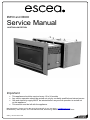
IB850 and IB600
Service Manual
AUSTRALIAN EDITION
Important
•
•
•
•
This appliance should be serviced every 12 to 24 months
Any service operation should be carried out only by a suitably qualified and trained person
Gas and electricity supply MUST be isolated before any service operation is carried out
on this appliance.
This manual must be left with the appliance.
Manufactured by: Escea Ltd, PO Box 5277 Dunedin NZ, Ph: 03 479 0302, e: [email protected]
Distributed by: Glen Dimplex, Unit 2 205 Abbotts Road, Dandenong, Melbourne. Ph: +61 3 87873567
G8872_1 Service Manual AUS
2
Contents:
Page:
Error Codes
3
Cleaning the Log Set and Glass
5
Checking Operating Pressure
6
Removing / Cleaning Fan
7
Removing Electronic Draw
8
Replacing a Wireless Control
9
Gas Type Conversion
10
Annual Service Procedure
11
Wiring Diagram
12
G8872_1 Installation Manual AUS
3
Error Codes:
This gas fire has been designed to show error codes to help explain and identify any fault
situation that occurs.
These codes will appear on the wireless control in the form of a large letter “E” with a number
beside it. Codes can normally be reset by turning the heater off then on again at the wall.
The following table shows what each code means and possible ways to rectify the situation.
Error Code
PCB Over Temp
(Printed Circuit Board)
Flame Failure or
Power Flue trip
Suggested action
IB600 - Usually associated with a four sided fascia being mounted too
high resulting in an insufficient air gap between the lower removable strip
and the bottom of the outer fascia.
IB850 - Usually insufficient cavity ventilation. Note: This error has a
permanent lock out and will require the unit to be reset 10 minutes after
the initial error (turning the power to the fire off "at the wall" then on again
after a few seconds).
The fire has tried to light three times and failed.
- Check gas supply and check other gas appliances to see if they are
affected. If you have two separate LPG cylinders, switch over to the full
bottle or contact your gas supplier. You may need to retry igniting the fire
a few times after re-establishing gas supply.
- Check the electrode placement in relation to the flame. Ensure it is well
enveloped in flame as per the diagram in the installation instructions.
Ensure no coals have dropped onto the ignition electrodes between the
burners.
- Ensure the electrodes are not contacting any metalwork including the
burners.
- Check that there has not been a significant reduction in pressure inside
the house (such as an extractor fan in a nearby kitchen) which can pull
flue gas back down through the firebox "snuffing" the flames.
Draught Diverter
Bimetallic Trip
The bimetallic snap disk mounted on the hood of the draught diverter at
the rear of the fire or on the lid of the fire has tripped. The possible causes
for this could include... A gust of wind pushing exhaust gases back down
the flue or a significant reduction in air pressure inside the house or cavity
which is pulling exhaust gases back down the flue (such as a extractor fan
in a nearby kitchen).
If installed into a tight masonry cavity it may indicate that the whole
installation is getting too hot and some additional ventilation into the cavity
may be required.
In the unlikely event that the fans have stalled, and the snap disk on the
lid of the fire has tripped, this would show an E3 also. Simply check that
the fans are running normally after resetting and running the fire again.
Note: This error has a permanent lock out and will require the unit to be reset 10 minutes
after the initial error (turning the power to the fire off "at the wall" then on again after a
few seconds).
G8872_1 Installation Manual AUS
4
Remote cannot
communicate with
fire
The remote cannot communicate with the fire. Reasons for this could
include the fire being off "at the wall" i.e. a loss of power to the fire or the
remote is outside of its effective radio frequency range (too far away from
the fire). Typical Remote range is 1m to 12m.
The draught diverter temperature sensor has detected that the air
temperature at its outlet has exceeded its maximum limit. This would
indicate similar conditions to the E3 error above.
Draught Diverter
Temp Sensor Trip
Note: This error has a permanent lock out and will require the unit to be reset 10 minutes
after the initial error (turning the power to the fire off "at the wall" then on again after a
few seconds).
The valve temperature sensor has detected abnormally high temperatures
around the valves. This is an unlikely fault and should it occur please
contact that Escea agent you purchased the fire from.
Valve Temp Sensor
Trip
Note: This error has a permanent lock out and will require the unit to be reset 10 minutes
after the initial error (turning the power to the fire off "at the wall" then on again after a
few seconds).
This indicates a fault with one of the two temperature sensors installed in
your fire. Resetting the fire (turning the power to the fire off then on again
after a few seconds) and if the fault reappears, please contact your Escea
sales agent to organise a replacement sensor.
Temp Sensor Error
Note: This error has a permanent lock out and will require the unit to be reset 10 minutes
after the initial error (turning the power to the fire off "at the wall" then on again after a
few seconds).
G8872_1 Installation Manual AUS
5
Cleaning the log set and glass:
NEVER EVER RUB THE FASCIA
The outside of the fascias must only be cleaned with a damp cloth. The high temp silver
powder coating that is used on Escea fascia parts contains certain amounts of aluminium
that when rubbed too hard will oxidise leaving a big black smudge that cannot be
removed.
This is a service procedure that will need to be carried out when ever soot builds up on logs
and/or inside of glass.
If soot build up becomes excessive or regular then one of the following actions may be required;
• Reset gas pressure, pressure may be too high;
• Reposition log set so that front edge of each log is just behind each row of holes in burner
top;
• Clear any blockage from primary air port of burner;
• Check to make sure flue system is drawing well.
Step 1:
Lift off the inner fascia by unscrewing the
two screws situated underneath. pull
the base of inner fascia out by
lifting it up and off.
Step 2:
Unscrew the top glass
retainer and remove it. Take
care that the glass does
not fall forwards at this
stage.
Step 3:
Lift out glass and place it carefully
aside.
Step 4:
Take out log set and gently brush any
soot from log with a soft hearth brush.
The burner tops can be vacuumed to
remove any excess material.
Step 5:
Clean the inside and outside of glass with
normal glass cleaning products. use a CLEAN
DRY cloth only. Stubborn marks may be cleaned
with a ceramic glass cleaner.
G8872_1 Installation Manual AUS
6
Step 6:
Replace in opposite order and test run heater.
Checking Operating Pressure:
This is done at the regulator located at the front RH corner of the appliance.
This is best done before the fascia panels have been fitted to avoid fascia damage. Pressure
test points are available for both inlet and operating test pressure (as shown below).
1) Remove inlet pressure test point screw and attach manometer tube.
2) Run the heater on full (all three burners running) and measure inlet pressure. If
pressure does not fall within the maximum or minimum pressures listed on the table
below then reassess installation pipe size or upstream regulator settings. Replace inlet
test point screw.
3) Remove the operating pressure test point screw. Connect manometer tube and
measure pressure with heater running on full (all three burners running).
4) The heater regulator pressure has been factory set to 0.87KPa for Natural Gas
heaters and 2.30Kpa for LPG heaters. Please check that the operating pressure is
exactly as listed and if not, adjust screw in centre of regulator until pressure is correct.
5) Replace operating test point screw and leak test both test points.
B
A
C
D
A = Operating Pressure test point
B = Pressure adjustment screw
C = Inlet pressure test point
D = Inlet gas connection
IB850 and IB600 Pressure Table
Gas Type
LPG
NG
Minimum Inlet Pressure
2.5KPa
1.2KPa
Maximum Inlet Pressure
3.5KPa
5.0KPa
Operating Pressure
2.30KPa
0.87KPa
G8872_1 Installation Manual AUS
7
Removing or Cleaning Fan
As part of regular service procedure, it is recommended that the fan is removed for cleaning.
Dust will build up on the fan rotor and in the cavity where the fan is located. This can be removed
by the service person using a vacuum cleaner.
Step One:
ISOLATE THE POWER TO
THE FIRE BEFORE PROCEEDURE
Remove front glass and
log set as described on
page 5.
Step Two:
Remove fire box from
heater by taking out the
screws from each corner
and Pulling fire directly
outwards
(as shown).
Remove screws from
each corner of firebox
Pull firebox out
Step Three:
Take out the 7 screws
on top of fan box unit
Step Four:
Lift the fan unit up and
out as far as the wires
will allow. Unplug wires to
fully remove fan assembly.
Step Five:
Clean fans, removing all dust build up.
Replace fans and fire box.
G8872_1 Installation Manual AUS
Pull up and outwards
8
Replacing Electronic Draw
All of the electronic components of the heater have been located on a removable draw.
This draw is located on the left hand outer side of the IB850 and under the front burner of the
IB600. On the back of the draw are two large connectors that unplug as the draw is removed so
only the three wires connecting the electronics to the igniters and flame rod must be removed
manually from the PCB (Printed Circuit Board).
ISOLATE THE POWER TO THE FIRE BEFORE PROCEEDURE.
Step one:
IB850 = Remove outer fascia
by taking out two screws located
behind the bottom fascia trim panel
IB600 = Remove the bottom
fascia trim panel
Step Two:
Take out the two screws at each end of the electronic draw and pull draw directly outwards
Step Three:
Carefully remove the two wires shown
from the white ignition module.
Wire Entry:
IB600
1. Flame Rod
2. Spark Lead
IB850
G8872_1 Installation Manual AUS
9
Replacing a wireless control:
If the wireless control becomes lost or damaged, a new one can be ordered from any Escea
retail agent.
When you have the new remote, the following procedure needs to be followed to “teach” the
remote to only communicate with that fire.
1. Ensure the fire and remote are set to “Off” (only the time is displayed on the remote).
2. Turn on the fire using the Aux On/Off (red) button on the front of the fire under the removable
bottom front panel.
IB850
IB600
3. Wait 1 ½ minutes until the fan begins to operate, wait a further 15 seconds and then press
and hold the auxiliary On/Off button for no less than 8 seconds (Note: This will also extinguish
the fire).
4. Immediately after releasing the Aux On/Off button turn on the remote control and wait four to
five minutes. During this time the fire will re-ignite.
NOTE: During this period the fire will listen for any coded remote signal and re-address itself to
this new code. So make sure the batteries of any other Escea remote that may be nearby are
removed.
5. The fire is now re-addressed to the new remote control.
Gas Type Conversion
Gas type conversion kits can be ordered from your Escea retailer under the following part
numbers;
NG-850
LPG-850
NG-600
LPG-850
Natural Gas Conversion Kit - IB850
LPG Conversion Kit - IB850
Natural Gas Conversion Kit - IB600
LPG Conversion Kit - IB600
If the heater had not been used before gas type conversion was required then Escea will credit
the cost of the conversion kit when the original parts are returned to Escea.
G8872_1 Installation Manual AUS
10
Gas Type Conversion Procedure:
Step one:
Remove inner fascia, glass
and logs (as described earlier
in this manual).
Service person may also wish
to remove the firebox to
increase the work space
within the heater.
Step two:
Take out front two burners
by removing the screws from
either end of the burner top
face. Burners can then be
lifted out.
Step 2
Step Three:
Unscrew rear burner clamp bracket
On left side.
Lift out the rear burner.
Step Four:
Change the three jets with the
jets supplied in kitset. Replace
the rear burner and clamp
bracket. Replace front two
burners with the burners
supplied in kitset.
Step five:
Take the regulator spring out
of the regulator by unscrewing
the pressure adjustment knob,
completely. Swap regulator
spring with the new spring that is
supplied in conversion kitset.
Replace adjustment screw.
Step six:
Reset gas pressure as per
instructions on page 6 of
this manual.
G8872_1 Installation Manual AUS
Step 3
Step 4
Step 5
11
Annual service procedure:
1. Isolate power to fire.
2. Remove front glass and clean inside of glass.
3. Remove logs and brush off any soot.
4. Remove burners and blow compressed air through them.
5. Remove jets and clean injector hole with solvent.
6. Remove firebox to give access to fan, brush and vacuum any
dust build up from fan blades.
7. Vacuum any dust from the cavity that houses the fan and
solenoid valves and from the ducts down each side of the heater
that lead to this cavity.
8. Test all joints for gas tightness.
9. Reassemble heater and check that operating pressure is correct.
2.3KPa LPG, 0.87KPa Natural Gas.
10. Check glass & Firebox tape and replace if necessary.
11. Check to make sure that flue system is intact, not in any way
blocked and that flue system is drawing correctly.
12. Trial heater with several start/stop cycles and trial fan-boost,
effect only and thermostat modes to ensure that all modes
function correctly.
G8872_1 Installation Manual AUS
12
Wiring Diagram:
G8872_1 Installation Manual AUS