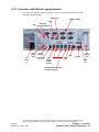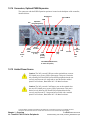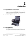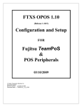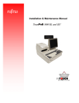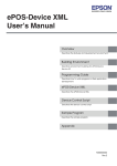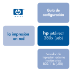
1
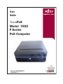
User
Guide
TeamPoS
Model 7000
F-Series
PoS Computer
Document D900000477
Revision 1.0
Title:
TeamPoS Model 7000 F-Series PoS
Computer System User Guide
(D900000477)
Date:
June 1, 2012
Version:
Version 1.0
Audience:
Corporate clients and field engineers
COPYRIGHT © 2012 FUJITSU FRONTECH NORTH AMERICA
INC. ALL RIGHTS RESERVED. TeamPoS 7000, F-Series, SHAPING
TOMORROW WITH YOU AND ASSOCIATED LOGOS ARE
TRADEMARKS OR REGISTERED TRADEMARKS OF FUJITSU
FRONTECH NORTH AMERICA INC. ALL OTHER MARKS ARE
THE REGISTERED TRADEMARKS OR TRADEMARKS OF THEIR
RESPECTIVE OWNERS IN THE UNITED STATES AND/OR OTHER
COUNTRIES.
The descriptions and information in this document are guidelines,
detailing the recommendations of Fujitsu Frontech North America Inc.
(FFNA).
Fujitsu endeavors to ensure that the information in this document is
correct and fairly stated. The information within this document has been
reviewed for accuracy, but as with most documents, errors may be found
and corrected in future revisions. Fujitsu Frontech North America Inc.
does not accept liability for any errors or omissions. The development of
Fujitsu products and services is continuous, and published information
may not be up to date. It is important to check the current position with
Fujitsu.
Contents
TeamPoS7000_User Guide (F-Series)_D900000477.pdf
Chapter 1. Overview
1.1 TeamPoS 7000 F-Series Overview ...................................................................................... 3
1.1.1 Features.................................................................................................................................................4
1.2 TeamPoS 7000 F-Series Peripherals .................................................................................. 5
1.2.1 LCD Monitors.......................................................................................................................................5
1.2.2 VF70 VFD ............................................................................................................................................5
1.2.3 Keypad+ MSR ......................................................................................................................................6
1.2.4 MSR ......................................................................................................................................................6
1.2.5 CT11 Thermal Printer...........................................................................................................................6
1.2.6 Epson TM-T88V Printer.......................................................................................................................7
1.2.7 Epson TM-H2000 Printer .....................................................................................................................7
1.2.8 Epson TM-H6000IV Printer .................................................................................................................7
1.2.9 Cash Drawers........................................................................................................................................8
1.2.10 LEDs and Buttons...............................................................................................................................9
1.2.11 Connectors, with Standard I/O..........................................................................................................11
1.2.12 Connectors, with Optional Displayport Expansion ..........................................................................12
1.2.13 Connectors, with Optional Legacy Expansion .................................................................................13
1.2.14 Connectors, Optional PUSB Expansion ...........................................................................................14
1.2.15 Limited Power Source ......................................................................................................................14
Chapter 2. Introduction
2.1 System Configurations and Components ......................................................................... 15
2.1.1 System illustration (F-Series model) ..................................................................................................15
2.2 System Configurations ..................................................................................................... 15
2.2.1 Hardware.............................................................................................................................................16
2.2.2 Operating Systems ..............................................................................................................................18
Chapter 3. Basic Operations
3.1 Turning the Power On ...................................................................................................... 19
3.2 Turning the Power Off...................................................................................................... 20
3.3 Adjusting the Displays...................................................................................................... 21
3.3.1 Displays (LCD)...................................................................................................................................21
3.3.2 Customer Display (VFD)....................................................................................................................21
TeamPoS7000_User Guide (F-Series)_D900000477.pdf
Revision 1.0 - June 1, 2012
Page 1
TeamPoS 7000 User Guide: Contents
3.4 Using the (Optional) MSR ................................................................................................ 21
3.5 Using the CT11 Printer ..................................................................................................... 23
3.5.1 Paper roll ............................................................................................................................................ 24
3.6 Cash Drawer Operations ................................................................................................... 26
3.6.1 Opening and closing the drawer......................................................................................................... 26
3.6.2 Inserting and removing till from drawer ............................................................................................ 26
Chapter 4. Daily Maintenance
4.1 Cleaning the Equipment.................................................................................................... 29
4.1.1 Cleaning the main unit ....................................................................................................................... 30
4.1.2 Cleaning the magnetic card reader (option) ....................................................................................... 30
4.1.3 Cleaning the printer............................................................................................................................ 30
4.1.4 Cleaning the print head and roller...................................................................................................... 31
Chapter 5. Troubleshooting
5.1 Troubleshooting ................................................................................................................ 33
5.2 Paper Jams......................................................................................................................... 34
5.3 Paper Jams Frequently ...................................................................................................... 34
5.4 Supplies ............................................................................................................................. 35
Appendix
Ensure Safe Use .........................................................................................................................i
Disclaimer ..................................................................................................................................i
Computer Viruses.......................................................................................................................i
Regulatory Information.............................................................................................................ii
Safety........................................................................................................................................iii
Getting Started .........................................................................................................................iv
Warning Symbols...................................................................................................................... v
Safety Considerations...............................................................................................................vi
Handling Precautions .............................................................................................................viii
Modifying or Reproducing the Unit.........................................................................................ix
Acronym Identification ............................................................................................................. x
TeamPoS7000_User Guide (F-Series)_D900000477.pdf
Revision 1.0 - June 1, 2012
Page 2
TeamPoS 7000 User Guide: Contents
1
Overview
1.1 TeamPoS 7000 F-Series Overview
Thank you for purchasing the TeamPoS 7000 system, which is Fujitsu’s Model 7000 series of
PoS computer systems. This manual is intended for personnel who operate the TeamPoS 7000
F-Series version. It provides notes on handling, describes basic operating procedures, and gives
supplementary information which operators should know before using the TeamPoS 7000
series of PoS computer systems.
We hope that the TeamPoS 7000 will help you operate your business in a more efficient
manner. This manual illustrates the TeamPoS Model 7000 F-Series PoS computer systems
(part of the KD02909-7000 series) and describes the procedures required for using these
systems.
The following sections provide a brief overview of the TeamPoS 7000 F-Series control units
as well as their peripherals.
TeamPoS 7000 F-Series
The TeamPoS Model 7000 family of products is a state-of-the-art Point of Sale (POS)
terminal. Built on industry standard platforms, the TeamPoS 7000 leverages Intel-embedded
components and standard operating systems, software applications and peripherals. It supports
standard PC components such as high-performance CPUs, memory, hard disk, video and audio.
Main components such as power supply, hard drives, etc. are shared between certain models.
The TeamPoS 7000 system can be used as a computer to run standard PC applications, such as
word processing, spreadsheets, etc., subject to operating system and licensing restrictions. This
system offers dual 2.5” hard disk or solid state drives, optical drive, on board LAN, 15”/12”/7”
LCD displays; USB, I/O expansion modules, and runs on a variety of software platforms.
THIS DOCUMENT CONTAINS CONFIDENTIAL INFORMATION, IS PROVIDED FOR FUJITSU CUSTOMER USE ONLY,
AND IS NOT TO BE SHARED WITH ANY THIRD PARTY WITHOUT FUJITSU’S PRIOR WRITTEN CONSENT.
Overview
Revision 1.0 - June 1, 2012
Chapter 1 - Overview
TeamPoS 7000 F-Series Overview - 3
The TeamPoS 7000 also contains functionality required by retail application software and are
“retail hardened” to support the harsh environments found in most retail stores. Depending on
the application requirements, there is a very large number of possible configurations. Memory
capacity, number of hard disks, CPU speed, and the number of powered RS-232 and USB ports
are selectable by the customer. Operating systems are also selectable.
The TeamPoS Model 7000 Series (KD02909-7000) F-Series PoS computer is available in
three standard models (that can be customized):
• TeamPoS 7000 Model F200, Celeron G540 CPU, 2GB RAM, 1x HDD 250GB
• TeamPoS 7000 Model F300, i3 CPU, 4GB RAM, 1x HDD 250GB
• TeamPoS 7000 Model F500, i5 CPU, 4GB RAM, 1x HDD 250GB
1.1.1 Features
Features include:
• Small footprint to free up counter space
• Full-flat LCDs (customer-facing and operator-facing) with infrared touch, resistive touch,
and non-touch
• Various microprocessor options (Celeron G540, Core-i3, Core-i5)
• Remote Management with Intel AMT (F300/F500)
• Dual disks
• RAID 0/1 support
• Optional integrated proximity sensor, speaker, microphone, and webcam on LCD displays
• Higher performance i3/i5 CPUs to handle applications with blazing speeds
• 2/4GB DDR3 memory, extendable to 8 GB
• Selectable high capacity storage (HDD: 250GB or SSD: 30/62GB)
• Security (RAID1) and higher performance (RAID0) with SSD or HDD RAID
• Optical drive
• Built to last for retail environment
• Anti-discoloration materials
• Several Operating Systems certified for long life management
• Cost-effective energy saving
• Power saving mode for CPU and LED backlit displays
• Compatible with previous Fujitsu peripherals and applications
THIS DOCUMENT CONTAINS CONFIDENTIAL INFORMATION, IS PROVIDED FOR FUJITSU CUSTOMER USE ONLY,
AND IS NOT TO BE SHARED WITH ANY THIRD PARTY WITHOUT FUJITSU’S PRIOR WRITTEN CONSENT.
Chapter 1 - Overview
4 - TeamPoS 7000 F-Series Overview
TeamPoS 7000 User Guide
TeamPoS7000_User Guide (F-Series)_D900000477.pdf
1.2 TeamPoS 7000 F-Series Peripherals
The TeamPoS 7000 F-Series supports various peripherals and settings.
1.2.1 LCD Monitors
15- and 12-inch LCD monitors for operator or customer displays; 7-inch customer display.
• Support for three types of panels: flat surface Resistive touch; IR touch with bezel, and
non-touch.
12/15" R/IR touch and non-touch LCDs
DV75 15" non-touchLCD
7" customer LCD
1.2.2 VF70 VFD
VFD VF70
• USB interface
THIS DOCUMENT CONTAINS CONFIDENTIAL INFORMATION, IS PROVIDED FOR FUJITSU CUSTOMER USE ONLY,
AND IS NOT TO BE SHARED WITH ANY THIRD PARTY WITHOUT FUJITSU’S PRIOR WRITTEN CONSENT.
Overview
Revision 1.0 - June 1, 2012
Chapter 1 - Overview
TeamPoS 7000 F-Series Peripherals - 5
1.2.3 Keypad+ MSR
40-key keypad with MSR (there is no stand-alone keypad)
• USB interface
• This Keypad+MSR is located on the right side of the LCD.
1.2.4 MSR
• USB interface
• This MSR is located on the right side of the LCD.
1.2.5 CT11 Thermal Printer
Thermal printer:
•
•
•
•
USB interface
300mm/s
16 shades of gray printing
Tool-less part replacement (thermal head, cutter, platen)
THIS DOCUMENT CONTAINS CONFIDENTIAL INFORMATION, IS PROVIDED FOR FUJITSU CUSTOMER USE ONLY,
AND IS NOT TO BE SHARED WITH ANY THIRD PARTY WITHOUT FUJITSU’S PRIOR WRITTEN CONSENT.
Chapter 1 - Overview
6 - TeamPoS 7000 F-Series Peripherals
TeamPoS 7000 User Guide
TeamPoS7000_User Guide (F-Series)_D900000477.pdf
1.2.6 Epson TM-T88V Printer
Thermal printer:
• USB interface
• 300 mm/s
• 58/80 mm paper roll sizes
1.2.7 Epson TM-H2000 Printer
Thermal/dot matrix printer:
• USB interface
• Drop-in paper loading
• MICR reader and franker
1.2.8 Epson TM-H6000IV Printer
Thermal/dot matrix printer:
• USB interface
• Multi-tone printing
• MICR reader and endorsement printer
THIS DOCUMENT CONTAINS CONFIDENTIAL INFORMATION, IS PROVIDED FOR FUJITSU CUSTOMER USE ONLY,
AND IS NOT TO BE SHARED WITH ANY THIRD PARTY WITHOUT FUJITSU’S PRIOR WRITTEN CONSENT.
Overview
Revision 1.0 - June 1, 2012
Chapter 1 - Overview
TeamPoS 7000 F-Series Peripherals - 7
1.2.9 Cash Drawers
1.2.9.1 TP15 standard cash drawer
Bill compartments: 5; coin compartments: 6, with media slot
1.2.9.2 Compact cash drawer
Bill compartments: 3; coin compartments: 6, with media slot
THIS DOCUMENT CONTAINS CONFIDENTIAL INFORMATION, IS PROVIDED FOR FUJITSU CUSTOMER USE ONLY,
AND IS NOT TO BE SHARED WITH ANY THIRD PARTY WITHOUT FUJITSU’S PRIOR WRITTEN CONSENT.
Chapter 1 - Overview
8 - TeamPoS 7000 F-Series Peripherals
TeamPoS 7000 User Guide
TeamPoS7000_User Guide (F-Series)_D900000477.pdf
1.2.10 LEDs and Buttons
The LED and button locations on the front panel are indicated below. Open the panel cover
door to access the controls and LEDs.
See the table on the following page for additional details.
HDD/SDD activity
door
latch
Optical
drive
activity
Open
optical drive
door
Optical
drive door
release
USB Port
HDD1/SSD1 Diagnostic
ON/OFF Switch
Reset Switch
HDD2/SSD2 Diagnostic
Fan Diagnostic
Power indicator
Memory Diagnostic
Caution: It is assumed that the user of this manual fully understands and
strictly adheres to proper Electrostatic Discharge (ESD) precautions. Failure
to adhere to precautions can cause damage to this equipment.
Always remove the power cord from the unit prior to performing any system
maintenance.
THIS DOCUMENT CONTAINS CONFIDENTIAL INFORMATION, IS PROVIDED FOR FUJITSU CUSTOMER USE ONLY,
AND IS NOT TO BE SHARED WITH ANY THIRD PARTY WITHOUT FUJITSU’S PRIOR WRITTEN CONSENT.
Overview
Revision 1.0 - June 1, 2012
Chapter 1 - Overview
TeamPoS 7000 F-Series Peripherals - 9
1.2.10.1 TeamPoS 7000 F-Series Front Panel Switch and LCD Matrix
Button
Button/LED
Position
Comment
HDD/SSD
activity
Top, on
right
This LED flashes to indicate
HDD/SSD read/write activity.
Reset
switch
Between
LEDs and
buttons
Resets system; all data in
memory will be lost.
HDD1/SSD1
Diagnostic
Leftmost
LED
This LED is illuminated when
HDD1/SSD1 is not detected.
HDD2/SSD2
Diagnostic
Second
from left
This LED is illuminated when
HDD2/SSD2 is not detected.
Fan
Diagnostic
Middle
LED
This LED is illuminated when
the BIOS detects a fan failure.
Memory
Diagnostic
Second
from right
This LED is illuminated when
the BIOS memory test detects a
memory error.
Power
Indicator
Rightmost
LED
This LED is lit when the power
is on.
THIS DOCUMENT CONTAINS CONFIDENTIAL INFORMATION, IS PROVIDED FOR FUJITSU CUSTOMER USE ONLY,
AND IS NOT TO BE SHARED WITH ANY THIRD PARTY WITHOUT FUJITSU’S PRIOR WRITTEN CONSENT.
Chapter 1 - Overview
10 - TeamPoS 7000 F-Series Peripherals
TeamPoS 7000 User Guide
TeamPoS7000_User Guide (F-Series)_D900000477.pdf
1.2.11 Connectors, with Standard I/O
The standard I/O connectors are located on the backplane of the controller, identified below.
AC
Power
In
Cash
drawer
GND
Audio
Line Out
LAN
Cash Drawer 24V
(1 or 2)
PUSB
(usually
printer)
USB
(x2)
Unused
PCI
Express
slot
VGA
out
12V PUSB (VFD, Monitors,
or other 12V power)
THIS DOCUMENT CONTAINS CONFIDENTIAL INFORMATION, IS PROVIDED FOR FUJITSU CUSTOMER USE ONLY,
AND IS NOT TO BE SHARED WITH ANY THIRD PARTY WITHOUT FUJITSU’S PRIOR WRITTEN CONSENT.
Overview
Revision 1.0 - June 1, 2012
Chapter 1 - Overview
TeamPoS 7000 F-Series Peripherals - 11
1.2.12 Connectors, with Optional Displayport Expansion
The connectors with the Displayport Expansion option are located on the backplane of the
controller, identified below.
Displayport
COM1
COM2
USB
Split PS/2
Mic (mouse/keyboard)
AC
Power
In
Cash
drawer
GND
Audio
Line Out
LAN
Cash Drawer 24V
(1 or 2)
PUSB
(usually
printer)
USB
(x2)
PCI
Express
slot
Unused
VGA
out
12V PUSB (VFD, Monitors,
or other 12V power)
THIS DOCUMENT CONTAINS CONFIDENTIAL INFORMATION, IS PROVIDED FOR FUJITSU CUSTOMER USE ONLY,
AND IS NOT TO BE SHARED WITH ANY THIRD PARTY WITHOUT FUJITSU’S PRIOR WRITTEN CONSENT.
Chapter 1 - Overview
12 - TeamPoS 7000 F-Series Peripherals
TeamPoS 7000 User Guide
TeamPoS7000_User Guide (F-Series)_D900000477.pdf
1.2.13 Connectors, with Optional Legacy Expansion
The connectors with the Legacy Expansion option are located on the backplane of the
controller, identified below.
Displayport
COM1 to COM6
USB
Split PS/2
Mic (mouse/keyboard)
AC
Power
In
Cash
drawer
GND
Audio
Line Out
LAN
Cash Drawer 24V
(1 or 2)
PUSB
(usually
printer)
USB
(x2)
Unused
PCI
Express
slot
VGA
out
12V PUSB (VFD, Monitors,
or other 12V power)
THIS DOCUMENT CONTAINS CONFIDENTIAL INFORMATION, IS PROVIDED FOR FUJITSU CUSTOMER USE ONLY,
AND IS NOT TO BE SHARED WITH ANY THIRD PARTY WITHOUT FUJITSU’S PRIOR WRITTEN CONSENT.
Overview
Revision 1.0 - June 1, 2012
Chapter 1 - Overview
TeamPoS 7000 F-Series Peripherals - 13
1.2.14 Connectors, Optional PUSB Expansion
The connectors with the PUSB Expansion option are located on the backplane of the controller,
identified below.
Displayport
12V PUSB x5
USB
Split PS/2
Mic (mouse/keyboard)
AC
Power
In
Cash
drawer
GND
Audio
Line Out
LAN
Cash Drawer 24V
(1 or 2)
PUSB
(usually
printer)
PCI
Express
slot
Unused
USB
(x2)
VGA
out
12V PUSB (VFD, Monitors,
or other 12V power)
1.2.15 Limited Power Source
Caution: The 24V powered USB port on the terminal does not meet
UL limited power source (LPS) requirements. This port is limited to
only allowing 24V Retail POS powered USB peripherals that do not
exceed a rated current of 4 Amps and are provided with a molded
plastic Fire Enclosure, Rated Min. 94V-1 or Metal enclosure.
Caution: The 24V powered Cash Drawer port on the terminal does
not meet UL limited power source (LPS) requirements. This port is
limited to only allowing 24V Retail POS peripherals that do not
exceed a rated current of .2 Amps and are provided with a molded
plastic Fire Enclosure, Rated Min. 94V-1 or Metal enclosure.
THIS DOCUMENT CONTAINS CONFIDENTIAL INFORMATION, IS PROVIDED FOR FUJITSU CUSTOMER USE ONLY,
AND IS NOT TO BE SHARED WITH ANY THIRD PARTY WITHOUT FUJITSU’S PRIOR WRITTEN CONSENT.
Chapter 1 - Overview
14 - TeamPoS 7000 F-Series Peripherals
TeamPoS 7000 User Guide
TeamPoS7000_User Guide (F-Series)_D900000477.pdf
2
Introduction
2.1 System Configurations and Components
This chapter describes the system configuration, and also the component names and functions.
A trained service engineer installs the TeamPoS 7000 F-Series PoS computer system and its
software in the store where it will be used. After installation, it is officially handed over to the
user. See the operation manual or the specifications of the application package you are using
for more information on how to use the workstation.
2.1.1 System illustration (F-Series model)
2.2 System Configurations
The TeamPoS 7000 F-Series PoS computer system can be configured with several optional
units, which can be selected in accordance with the style and the scale of the store operation.
Check that you have received the components and accessories that you ordered.
THIS DOCUMENT CONTAINS CONFIDENTIAL INFORMATION, IS PROVIDED FOR FUJITSU CUSTOMER USE ONLY,
AND IS NOT TO BE SHARED WITH ANY THIRD PARTY WITHOUT FUJITSU’S PRIOR WRITTEN CONSENT.
TeamPoS7000_User Guide (F-Series)_D900000477.pdf
Revision 1.0 - June 1, 2012
Chapter 2 - Introduction
System Configurations and Components - 15
2.2.1 Hardware
TeamPoS 7000
F-Series
CPU
Memory
Model TP7000F200
Model TP7000F300
Model TP7000F500
Intel® Dual Core
Celeron G540
2.5GHz
Intel® Core i3
2120 3.3GHz
Intel® Core i5
3.1 GHz
Standard 2GB
DDR3 SO-DIMM
2 slots
Standard 4GB DDR3 SO-DIMM 2
slots
Max. 8GB (for 64-bit OS)
Storage
HDD: 250GB, 1 (1 open)
SSD: 30/62GB, 1 (1 open)
2.5" SATA x 2, RAID 0/1
LCD Displays
Option: 12"/15" color LCD
Option: integrated Webcam
Cooling
Temperature controlled fan
Standard I/O
USB x 3 (including one USB port located on front panel; see
page 9)
PUSB (12V) x 3
PUSB (24V) x 1
VGA x 1
LAN RJ-45 (10 BASE-T/100 BASE-TX/1000BASE-T) x 1
Cash Drawer RJ-12 x 1
(Y-cable option for second cash drawer)
Audio Line Out x 1
Displayport
Expansion
Option
RS232C D-sub 9pin x 2
Displayport
USB
Split PS/2 keyboard/mouse connector
Mic In
Legacy
Expansion
Option
Standard I/O and Displayport Expansion, plus:
RS232C D-sub 9pin x 4
PUSB Expansion
Option
Standard I/O and Displayport Expansion, plus:
12V PUSB x5
Color
Ocean Black
Dimensions
340mm (W) x 365mm (D) x 106 mm (H) mm
Weight
8.2 kg (18 lb.)
Main Unit
THIS DOCUMENT CONTAINS CONFIDENTIAL INFORMATION, IS PROVIDED FOR FUJITSU CUSTOMER USE ONLY,
AND IS NOT TO BE SHARED WITH ANY THIRD PARTY WITHOUT FUJITSU’S PRIOR WRITTEN CONSENT.
Chapter 2 - Introduction
16 - System Configurations
TeamPoS 7000 User Guide
TeamPoS7000_User Guide (F-Series)_D900000477.pdf
TeamPoS 7000
F-Series
Model TP7000F200
LCDs
Model TP7000F300
Model TP7000F500
D72R, 12” Color LCD Resistive Touchscreen dDisplay
D75R, 15” Color LCD Resistive Touchscreen Display
D75I, 15” Color LCD Infrared Touchscreen Display
D72, 12” Color LCD Non Touchscreen Display
D75, 15” Color LCD Non Touchscreen Display
LCD
Displays
(Option)
DV75 15” Color LCD Non Touchscreen Display
SD7, 7” USB LCD Display (w/ tilt bracket)
Factory Options: Monitor-integrated Webcam, MSR and
Keypad+MSR
VF70
Alphanumeric (20 digits x 2 lines),
245 (W) x 100 (H) mm
Pole type [tilt/swivel], Remote type [tilt/swivel]
Printer
(Option)
CT11
thermal printer
TM-T88V
thermal printer
TM-H2000
thermal/dot
matrix printer
TM-H6000IV
thermal/dot
matrix printer
Paper width: 58 mm/80 mm, printing speed: 300 mm/s
Paper width: 58 mm/80 mm, printing speed: 300 mm/s
Paper width: 58 mm/80 mm, printing speed: 4.0 lps
Paper width: 58 mm/80 mm, printing speed:5.7 lps
Keypad+MSR (Option)
40 key with MSR (ISO 1/2/3) attaches to monitor
MSR (Option)
ISO 1/2/3 attaches to monitor
Cash Drawer
(Option)
Standard
5 compartments for bills, 6 compartments for coins with
media slot; 8 coin insert; locking till cover
Compact
3 compartments for bills, 6 compartments for coins with
media slot
THIS DOCUMENT CONTAINS CONFIDENTIAL INFORMATION, IS PROVIDED FOR FUJITSU CUSTOMER USE ONLY,
AND IS NOT TO BE SHARED WITH ANY THIRD PARTY WITHOUT FUJITSU’S PRIOR WRITTEN CONSENT.
TeamPoS7000_User Guide (F-Series)_D900000477.pdf
Revision 1.0 - June 1, 2012
Chapter 2 - Introduction
System Configurations - 17
2.2.2 Operating Systems
The TeamPoS 7000 can be ordered with the following Operating Systems:
•
•
•
•
•
•
•
•
•
Microsoft Windows POSReady 7 (32/64-bit)
Microsoft Windows POSReady 2009
Microsoft WEPOS
Windows XP Professional
Windows 7 Professional (32/64-bit)
Windows Server 2008 (32/64-bit)
SUSE Linux SLED 11 (1 year Support)
SUSE Linux SLED 11 (3 year Support)
Customer-provided Linux option
THIS DOCUMENT CONTAINS CONFIDENTIAL INFORMATION, IS PROVIDED FOR FUJITSU CUSTOMER USE ONLY,
AND IS NOT TO BE SHARED WITH ANY THIRD PARTY WITHOUT FUJITSU’S PRIOR WRITTEN CONSENT.
Chapter 2 - Introduction
18 - System Configurations
TeamPoS 7000 User Guide
TeamPoS7000_User Guide (F-Series)_D900000477.pdf
3
Basic Operations
3.1 Turning the Power On
If the unit has been off for at least five seconds, take the following steps to power it up.
1. Slide up the power switch cover which is located on the right side of the front of the
computer.
2. Press the power switch to start the computer. The computer will start after a brief delay.
3. Slide the power switch cover back down to prevent accidentally pressing the power button.
NOTE: If nothing is displayed on the screen for 10 seconds or more after the
power has been turned on, verify the following:
•
•
•
•
Is the power indicator lit (see page 9)? If not, the system is not receiving power.
Is the power circuit active?
Is the power cord connected to the outlet?
Was the power turned back on within five seconds of being turned off?
(The power must be not turned back on until at least five seconds after the power
has been turned off.)
• If the above checks reveal no abnormalities, contact your support department.
THIS DOCUMENT CONTAINS CONFIDENTIAL INFORMATION, IS PROVIDED FOR FUJITSU CUSTOMER USE ONLY,
AND IS NOT TO BE SHARED WITH ANY THIRD PARTY WITHOUT FUJITSU’S PRIOR WRITTEN CONSENT.
TeamPoS7000_User Guide (F-Series)_D900000477.pdf
Revision 1.0 - June 1, 2012
Chapter 3 - Basic Operations
Turning the Power On - 19
3.2 Turning the Power Off
Make sure that all the work for the day is completed before turning off the power. If the unit is
on, take the following steps to shut it off.
1. Shut down the software. This should turn off the unit.
Turning the power off while the software is operating may corrupt the
programs and data on the disc.
2. If the unit is still powered up after you have shut down the software, take the following
steps:
3. Slide up the power switch cover which is located on the right side of the front of the
computer.
4. Press the power switch to power down the computer.
NOTE: When the power has been disconnected, wait at least five seconds
before turning it back on.
Turning the power off while the software is operating may corrupt the
programs and data on the disc.
Follow the software prompts when turning off the power.
THIS DOCUMENT CONTAINS CONFIDENTIAL INFORMATION, IS PROVIDED FOR FUJITSU CUSTOMER USE ONLY,
AND IS NOT TO BE SHARED WITH ANY THIRD PARTY WITHOUT FUJITSU’S PRIOR WRITTEN CONSENT.
Chapter 3 - Basic Operations
20 - Turning the Power Off
TeamPoS 7000 User Guide
TeamPoS7000_User Guide (F-Series)_D900000477.pdf
3.3 Adjusting the Displays
3.3.1 Displays (LCD)
The displays are pole mounted. They display transaction and advertisement information to the
customers or operator. The LCDs can be swiveled and tilted backwards and forwards.
3.3.2 Customer Display (VFD)
The customer VFD display is mounted behind the LCD display. It displays transaction
information to the customer. The display panel of the VF70 customer display can be swiveled
through approximately 300 degrees. Both displays can be tilted backwards and forwards.
VF70
3.4 Using the (Optional) MSR
The magnetic card reader reads information written on the magnetic stripe of a magnetic card.
NOTE:
• Use only the specified magnetic card reader.
• Keep magnetic stripes clean. If a magnetic stripe is contaminated with dust, oil or water, this
may cause an error, result in a magnetic head fault, or degrade the performance of the
magnetic head.
• Do not lubricate the magnetic card reader.
THIS DOCUMENT CONTAINS CONFIDENTIAL INFORMATION, IS PROVIDED FOR FUJITSU CUSTOMER USE ONLY,
AND IS NOT TO BE SHARED WITH ANY THIRD PARTY WITHOUT FUJITSU’S PRIOR WRITTEN CONSENT.
TeamPoS7000_User Guide (F-Series)_D900000477.pdf
Revision 1.0 - June 1, 2012
Chapter 3 - Basic Operations
Adjusting the Displays - 21
• If anything falls into the slot, use tweezers to remove it.
Data corruption:
Do not expose the magnetic card reader to strong magnetic fields, otherwise
the data may be lost.
1. Slide a magnetic card through the slot on the right side. Hold the card lightly, and slide it in
the slot on the right side, paying attention to the direction of the arrow.
2. Move the magnetic stripe card in the direction of the arrow. Move the magnetic card from
the far end of the slot to the front.
NOTE: The MSR reader may not be able to read the magnetic stripe card
correctly if the movement of the card is stopped midway, if the card is
not moved at a constant speed, or if the card is not moved parallel to
the slot.
3. Move the magnetic stripe card to the front of the slot and then remove it. When the
magnetic stripe card is read correctly, a confirmation beep sounds.
NOTE: If multiple beeps sound, retry the operation.
THIS DOCUMENT CONTAINS CONFIDENTIAL INFORMATION, IS PROVIDED FOR FUJITSU CUSTOMER USE ONLY,
AND IS NOT TO BE SHARED WITH ANY THIRD PARTY WITHOUT FUJITSU’S PRIOR WRITTEN CONSENT.
Chapter 3 - Basic Operations
22 - Using the (Optional) MSR
TeamPoS 7000 User Guide
TeamPoS7000_User Guide (F-Series)_D900000477.pdf
3.5 Using the CT11 Printer
This section describes the names and functions of the thermal printer components and explains
how to open and close the printer cover and load the paper roll. The procedure for loading and
removing the paper roll varies depending on whether the paper is being used. Load and remove
the receipt paper roll by following the appropriate procedures.
Please refer to the printer documentation for the other printers supported by the
TeamPoS 7000.
• The names and the functions of each component of the printer unit are described below.
(1) Top cover
(2) Print head
(3) Power LED
(4) Paper LED
(5) Error LED
(6) Feed button
Legend
1
Top cover
Open this cover to replace the paper roll.
2
Print head
Does the printing.
3
Power LED
Lights blue when power is applied.
4
Paper LED
Lights amber when paper level is low or empty.
5
Error LED
Lights red when the top cover is open or when the roll is near the
end. Blinks when an error has occurred.
6
Feed button
Press this switch when inserting or advancing the receipt paper roll.
THIS DOCUMENT CONTAINS CONFIDENTIAL INFORMATION, IS PROVIDED FOR FUJITSU CUSTOMER USE ONLY,
AND IS NOT TO BE SHARED WITH ANY THIRD PARTY WITHOUT FUJITSU’S PRIOR WRITTEN CONSENT.
TeamPoS7000_User Guide (F-Series)_D900000477.pdf
Revision 1.0 - June 1, 2012
Chapter 3 - Basic Operations
Using the CT11 Printer - 23
3.5.1 Paper roll
The paper roll must be loaded while the power is on. To replace the paper roll, you must open
the printer top cover.
1. Lift the top cover as far as it will go.
Top cover
Paper holder
Keyboard:
Do not touch the keyboard while replacing the paper roll. Otherwise, the
printer may operate and catch your clothing or hair.
Print Head is Hot
Immediately after printing, the print head is very hot. To prevent burns, allow
the printer sufficient time to cool before replacing the paper roll.
2. Remove the original paper roll or core.
3. Load the paper roll. Gently drop the paper roll into the paper holder and make sure that the
end of the paper faces down.
THIS DOCUMENT CONTAINS CONFIDENTIAL INFORMATION, IS PROVIDED FOR FUJITSU CUSTOMER USE ONLY,
AND IS NOT TO BE SHARED WITH ANY THIRD PARTY WITHOUT FUJITSU’S PRIOR WRITTEN CONSENT.
Chapter 3 - Basic Operations
24 - Using the CT11 Printer
TeamPoS 7000 User Guide
TeamPoS7000_User Guide (F-Series)_D900000477.pdf
NOTE:
4. Pull the paper out so that it runs straight, then close the top cover. It should click into place.
Do not move the paper guides.
THIS DOCUMENT CONTAINS CONFIDENTIAL INFORMATION, IS PROVIDED FOR FUJITSU CUSTOMER USE ONLY,
AND IS NOT TO BE SHARED WITH ANY THIRD PARTY WITHOUT FUJITSU’S PRIOR WRITTEN CONSENT.
TeamPoS7000_User Guide (F-Series)_D900000477.pdf
Revision 1.0 - June 1, 2012
Chapter 3 - Basic Operations
Using the CT11 Printer - 25
3.6 Cash Drawer Operations
3.6.1 Opening and closing the drawer
The drawer normally opens according to keyboard operation, for example, when the Total key
is pressed. However, if you wish to open the drawer in an emergency such as during a power
failure or when the unit is not powered, use the drawer key.
• To open the drawer, insert the drawer key into the keyhole and turn the key clockwise.
• When you shut the drawer, the lock engages again.
• Push the drawer to close it.
NOTE: No records are entered into the journal when the drawer is opened
using the drawer key. It is recommended that you use the drawer key
only in emergencies.
3.6.2 Inserting and removing till from drawer
• Open the cash drawer and pull it out completely.
• Lift the till. If applicable, remove the coin tray first. Then, hold both sides of the cash till and
lift it.
THIS DOCUMENT CONTAINS CONFIDENTIAL INFORMATION, IS PROVIDED FOR FUJITSU CUSTOMER USE ONLY,
AND IS NOT TO BE SHARED WITH ANY THIRD PARTY WITHOUT FUJITSU’S PRIOR WRITTEN CONSENT.
Chapter 3 - Basic Operations
26 - Cash Drawer Operations
TeamPoS 7000 User Guide
TeamPoS7000_User Guide (F-Series)_D900000477.pdf
• Lift the cash till and pull it out towards you.
• To insert the cash till into the drawer, open the drawer completely. Then, perform the above
steps in reverse order.
THIS DOCUMENT CONTAINS CONFIDENTIAL INFORMATION, IS PROVIDED FOR FUJITSU CUSTOMER USE ONLY,
AND IS NOT TO BE SHARED WITH ANY THIRD PARTY WITHOUT FUJITSU’S PRIOR WRITTEN CONSENT.
TeamPoS7000_User Guide (F-Series)_D900000477.pdf
Revision 1.0 - June 1, 2012
Chapter 3 - Basic Operations
Cash Drawer Operations - 27
THIS DOCUMENT CONTAINS CONFIDENTIAL INFORMATION, IS PROVIDED FOR FUJITSU CUSTOMER USE ONLY,
AND IS NOT TO BE SHARED WITH ANY THIRD PARTY WITHOUT FUJITSU’S PRIOR WRITTEN CONSENT.
Chapter 3 - Basic Operations
28 - Cash Drawer Operations
TeamPoS 7000 User Guide
TeamPoS7000_User Guide (F-Series)_D900000477.pdf
4
Daily Maintenance
This chapter describes how to clean the equipment and replace consumables.
4.1 Cleaning the Equipment
The following cleaning operations must be performed as required in order to ensure reliability.
NOTE: Observe the following cautions when cleaning the equipment.
• Switch off the equipment before cleaning.
• Use a solution of mild detergent diluted in water to clean the exterior
surfaces.
• Do not use a wet or chemically treated cloth or volatile chemicals
such as paint thinner to clean the equipment. Doing so may damage
the surface.
THIS DOCUMENT CONTAINS CONFIDENTIAL INFORMATION, IS PROVIDED FOR FUJITSU CUSTOMER USE ONLY,
AND IS NOT TO BE SHARED WITH ANY THIRD PARTY WITHOUT FUJITSU’S PRIOR WRITTEN CONSENT.
TeamPoS7000_User Guide (F-Series)_D900000477.pdf
Revision 1.0 - June 1, 2012
Chapter 4 - Daily Maintenance
Cleaning the Equipment - 29
4.1.1 Cleaning the main unit
Wipe the surface with a soft cloth such as gauze that has been moistened with neutral detergent.
The red rectangles in following illustrations show the ventilation holes in the front and back of
the F-Series models. These holes must be kept clean and remain unobstructed in order to
prevent excessive internal temperatures.
Caution: When cleaning, never spray any liquids directly onto the unit.
Always spray onto a cleaning cloth and then wipe to clean.
4.1.2 Cleaning the magnetic card reader (option)
The read head of the magnetic card reader can become severely soiled with use. If you continue
to use a magnetic card reader with a dirty read head, the reader may fail to read data correctly.
Clean the read head at regular intervals (about once every two months).
Use a cleaning card to clean the head. Using the same procedure as that for reading a magnetic
card, slide the cleaning card through the reader four to five times for each side. Note that the
magnetic card reader is optional.
NOTE: Use of the Fujitsu cleaning card (Product number D99L-1001-0060)
is recommended.
4.1.3 Cleaning the printer
Clean the printer at regular intervals (roughly about once every six months). If not kept clean,
paper debris and dust are likely to accumulate, which may degrade the print quality and/or
cause paper jams.
To clean the printer, remove the printer head cover (see “Cleaning the print head and roller”).
and remove any debris in the printer.
Do not touch the print head immediately after printing. Allow it to cool before
attempting to clean it.
THIS DOCUMENT CONTAINS CONFIDENTIAL INFORMATION, IS PROVIDED FOR FUJITSU CUSTOMER USE ONLY,
AND IS NOT TO BE SHARED WITH ANY THIRD PARTY WITHOUT FUJITSU’S PRIOR WRITTEN CONSENT.
Chapter 4 - Daily Maintenance
30 - Cleaning the Equipment
TeamPoS 7000 User Guide
TeamPoS7000_User Guide (F-Series)_D900000477.pdf
4.1.4 Cleaning the print head and roller
Use a wet cloth with alcohol (ethyl alcohol) or a light cleaning solution which is squeezed
tightly, or just use a dry cloth. Do not allow any liquids to enter the device in order to prevent
damage occurring to the device when you use cleaning liquid and do not use volatile materials
such as thinner or benzene because such materials may cause corrosion or remove color from
the frame.
THIS DOCUMENT CONTAINS CONFIDENTIAL INFORMATION, IS PROVIDED FOR FUJITSU CUSTOMER USE ONLY,
AND IS NOT TO BE SHARED WITH ANY THIRD PARTY WITHOUT FUJITSU’S PRIOR WRITTEN CONSENT.
TeamPoS7000_User Guide (F-Series)_D900000477.pdf
Revision 1.0 - June 1, 2012
Chapter 4 - Daily Maintenance
Cleaning the Equipment - 31
THIS DOCUMENT CONTAINS CONFIDENTIAL INFORMATION, IS PROVIDED FOR FUJITSU CUSTOMER USE ONLY,
AND IS NOT TO BE SHARED WITH ANY THIRD PARTY WITHOUT FUJITSU’S PRIOR WRITTEN CONSENT.
Chapter 4 - Daily Maintenance
32 - Cleaning the Equipment
TeamPoS 7000 User Guide
TeamPoS7000_User Guide (F-Series)_D900000477.pdf
5
Troubleshooting
This chapter provides information needed for troubleshooting and explains how to clear paper
jams. Read this chapter if you notice abnormalities with the unit.
If you suspect that the unit is faulty, contact your support department.
5.1 Troubleshooting
A symptom that appears to indicate a failure, may not actually be a failure. In such a case, refer
to the applicable part of the following table to identify the true cause of the problem.
If an error message appears on the operator display, refer to the operation manual or the
specifications of the application package being used.
Symptom
Common Causes
Check the following:
The unit cannot be turned on.
•
•
Check that the power is turned
on. Check:
•
Printed characters are faint.
The paper is soiled.
Printing is disabled.
•
•
•
Printing is smudged.
The unit is not plugged in.
The main circuit breaker for
the power outlet is off.
Power failure
•
•
AC Outlet
Main circuit breaker
The print head is dirty.
The print head has reached
the end of its service life.
The paper being used is not
of the specified type.
Clean the print head.
Replace the printer.
Use the paper of the specified
type.
An abnormal sound is heard or
a paper jam occurs during
printing.
•
Foreign objects such as
paper debris or paper clips
have fallen inside the
printer.
Check the inside of the printer
for paper debris or paper clips.
The printer fails to operate.
•
The head cover is open.
Make sure that the lock levers
on both left and right edges of
the head cover are locked.
LCD screen is dark.
•
The brightness control is set
incorrectly.
Adjust the brightness control.
The speaker sound volume is
too low or no sound can be
heard.
•
The speaker sound volume
is set incorrectly
Adjust the speaker volume
control.
THIS DOCUMENT CONTAINS CONFIDENTIAL INFORMATION, IS PROVIDED FOR FUJITSU CUSTOMER USE ONLY,
AND IS NOT TO BE SHARED WITH ANY THIRD PARTY WITHOUT FUJITSU’S PRIOR WRITTEN CONSENT.
TeamPoS7000_User Guide (F-Series)_D900000477.pdf
Revision 1.0 - June 1, 2012
Chapter 5 - Troubleshooting
Troubleshooting - 33
5.2 Paper Jams
If the receipt paper roll jams, open the head cover and remove the paper roll. Be careful not to
touch the keyboard or the print head.
Print Head is Hot
Immediately after printing, the print head is very hot. To prevent burns, allow
the printer sufficient time to cool before replacing the paper roll.
To prevent paper jams, do not hold or pull the paper while it is being fed. In particular, note that
if the receipt paper roll is pulled out before it is cut, a paper jam will occur easily.
Open the top cover:
1. Open the top cover and pull the roll paper. Set the correct position as shown below for the
CT11 (please refer to the printer documentation for the other printers supported by the
TeamPoS 7000).
2. Close the cover.
Print Head is Hot
Immediately after printing, the print head is very hot. To prevent burns, allow
the printer sufficient time to cool before replacing the paper roll.
5.3 Paper Jams Frequently
If a paper jam occurs frequently, check the points listed below.
If any components are found to have been set incorrectly, adjust them and, if staining or paper
debris is found inside the printer, clean the printer.
• Is the specified type of receipt roll paper being used in the printer?
• Is the receipt roll paper set correctly?
• Is the head cover locked?
• Is the print head set correctly?
• Is there any paper debris in the printer?
If a paper jam still occurs even after the above items have been checked, contact your support
department.
THIS DOCUMENT CONTAINS CONFIDENTIAL INFORMATION, IS PROVIDED FOR FUJITSU CUSTOMER USE ONLY,
AND IS NOT TO BE SHARED WITH ANY THIRD PARTY WITHOUT FUJITSU’S PRIOR WRITTEN CONSENT.
Chapter 5 - Troubleshooting
34 - Paper Jams
TeamPoS 7000 User Guide
TeamPoS7000_User Guide (F-Series)_D900000477.pdf
5.4 Supplies
Always use Fujitsu supplies as they are designed specifically for use with the unit. Order
Fujitsu supplies from the Fujitsu maintenance engineer or through Fujitsu at the following
numbers:
• North America: 1-800-538-8716, Option 3
• Outside North America: 1-972-728-7070
The supplies required for the equipment are listed below.
Use only the Fujitsu-specified supplies listed below for this product. If any
other supplies are used, component life may shorten or a failure may occur.
Product Name
Specification
Comments:
POS-C thermal roll paper
CA92002-014X
80mm × 80mm (dia.) for the thermal
printer
Cleaning card for the magnetic
card reader
D99L-1001-0060
Replace the cleaning card with a new
one if the one being used appears
stained.
THIS DOCUMENT CONTAINS CONFIDENTIAL INFORMATION, IS PROVIDED FOR FUJITSU CUSTOMER USE ONLY,
AND IS NOT TO BE SHARED WITH ANY THIRD PARTY WITHOUT FUJITSU’S PRIOR WRITTEN CONSENT.
TeamPoS7000_User Guide (F-Series)_D900000477.pdf
Revision 1.0 - June 1, 2012
Chapter 5 - Troubleshooting
Supplies - 35
THIS DOCUMENT CONTAINS CONFIDENTIAL INFORMATION, IS PROVIDED FOR FUJITSU CUSTOMER USE ONLY,
AND IS NOT TO BE SHARED WITH ANY THIRD PARTY WITHOUT FUJITSU’S PRIOR WRITTEN CONSENT.
Chapter 5 - Troubleshooting
36 - Supplies
TeamPoS 7000 User Guide
TeamPoS7000_User Guide (F-Series)_D900000477.pdf
Appendix
Ensure Safe Use
This manual contains important information required in order to use this product in a safe
manner. Before using the product, please read this manual thoroughly. Particularly, read and
understand the Safety Considerations described on page vi thoroughly before operating the
system.
Fujitsu Frontech North America has taken every effort to ensure that no personal injury or
economic damage will result to the user or any other person around the product. Always follow
the instructions contained in this manual when operating the TeamPoS 7000.
Disclaimer
The development of Fujitsu products and services is continuous and published information
may not be up to date. It is important to check the current position with Fujitsu Frontech North
America Inc. This document is not part of a contract or license save insofar as may be expressly
agreed.
READ THE ENTIRE MANUAL CAREFULLY BEFORE USING THIS PRODUCT.
INCORRECT USE OF THE PRODUCT MAY RESULT IN INJURY OR DAMAGE TO
USERS, BYSTANDERS OR PROPERTY.
While Fujitsu Frontech North America Inc. has sought to ensure the accuracy of all information
in this manual, Fujitsu Frontech North America Inc. assumes no liability to any party for any
damage caused by any error or omission contained in this manual, its updates or supplements,
whether such errors or omissions result from negligence, accident, or any other cause. In
addition, Fujitsu Frontech North America Inc. assumes no liability with respect to the
application or use of any product or system in accordance with descriptions or instructions
contain herein; including any liability for incidental or consequential damages arising
therefrom.
FUJITSU FRONTECH NORTH AMERICA INC. DISCLAIMS ALL WARRANTIES
REGARDING THE INFORMATION CONTAINED HEREIN, WHETHER EXPRESSED,
IMPLIED, OR STATUTORY.
Fujitsu Frontech North America Inc. reserves the right to make changes to any products
described herein without further notice and without obligation.
Computer Viruses
This product is used with operating systems that are inherently vulnerable to infection by
computer viruses. We strongly recommend that you protect this system through use of antivirus software.
THIS DOCUMENT CONTAINS CONFIDENTIAL INFORMATION, IS PROVIDED FOR FUJITSU CUSTOMER USE ONLY,
AND IS NOT TO BE SHARED WITH ANY THIRD PARTY WITHOUT FUJITSU’S PRIOR WRITTEN CONSENT.
TeamPoS7000_User Guide (F-Series)_D900000477.pdf
Revision 1.0 - June 1, 2012
Appendix - i
Regulatory Information
EMC
Radio Frequency Interference Requirements – U.S.A.
This equipment has been tested and found to comply with the limits for a Class A digital device
pursuant to Part 15 of the FCC Rules. These limits are designed to provide reasonable
protection against harmful interference when the equipment is operated in a commercial
environment. This equipment generates, uses, and can radiate radio frequency energy and, if
not installed and used in accordance with the instruction manual, may cause harmful
interference to radio communications. Operation of this equipment in a residential area is likely
to cause harmful interference in which case the user will be required to correct the interference
at his own expense.
Radio Frequency Interference Requirements – Canada
This Class A digital apparatus meets all the requirements of the Canadian
Interference-Causing Equipment Regulations.
Cet appareil numérique de la classe A respecte toutes les exigences du Règlement sur le
matériel brouilleur du Canada.
Radio Frequency Interference Requirements – Europe
This apparatus has been tested and found to comply with the limits for a Class A digital device,
per EN55022, for use in Information Technology equipment. In a domestic environment this
product may cause radio interference in which case the user may be required to take adequate
measures. This apparatus also meets the susceptibility requirements per EN55024. Overall, the
product qualifies for and bears the CE mark.
THIS DOCUMENT CONTAINS CONFIDENTIAL INFORMATION, IS PROVIDED FOR FUJITSU CUSTOMER USE ONLY,
AND IS NOT TO BE SHARED WITH ANY THIRD PARTY WITHOUT FUJITSU’S PRIOR WRITTEN CONSENT.
TeamPoS 7000 User Guide
ii - Appendix
TeamPoS7000_User Guide (F-Series)_D900000477.pdf
Safety
Lithium-Ion Battery
Caution: Danger of explosion if the lithium-ion (CMOS) battery is
incorrectly replaced. Replace only with the same or equivalent type
recommended by the manufacturer. Discard used batteries according
to the manufacturer’s instructions.
Limited Power Source
Caution: The 24V powered USB port on the terminal does not meet
UL limited power source (LPS) requirements. This port is limited to
only allowing 24V Retail POS powered USB peripherals that do not
exceed a rated current of 4 Amps and are provided with a molded
plastic Fire Enclosure, Rated Min. 94V-1 or Metal enclosure.
Caution: The 24V powered Cash Drawer port on the terminal does
not meet UL limited power source (LPS) requirements. This port is
limited to only allowing 24V Retail POS peripherals that do not
exceed a rated current of .2 Amps and are provided with a molded
plastic Fire Enclosure, Rated Min. 94V-1 or Metal enclosure.
Current Loading
Caution: Powered USB ports are used for POS peripherals. The
current loading for each port is specified in the following table.
Port
12V PUSB
12V PUSB
12V PUSB
24V PUSB
USB
USB
USB
USB (Option)
USB (Option)
Rating
+12V:1.3A,
+12V:0.4A,
+12V:0.4A,
+24V:0.2A,
+5V:0.5A
+5V:0.5A
+5V:0.5A
+5V:0.5A
+5V:0.5A
Note
+5V:0A
+5V:0A
+5V:0A
+5V:0A
For Printer
THIS DOCUMENT CONTAINS CONFIDENTIAL INFORMATION, IS PROVIDED FOR FUJITSU CUSTOMER USE ONLY,
AND IS NOT TO BE SHARED WITH ANY THIRD PARTY WITHOUT FUJITSU’S PRIOR WRITTEN CONSENT.
TeamPoS7000_User Guide (F-Series)_D900000477.pdf
Revision 1.0 - June 1, 2012
Appendix - iii
Getting Started
This manual is intended for personnel who operate the TeamPoS 7000. It provides notes on
handling, describes basic operating procedures, and gives supplementary information which
operators should know before using the TeamPoS 7000 series of PoS computer systems.
We hope that the TeamPoS 7000 will help you operate your business in a more efficient
manner.
Alert signals
This manual uses the following warning labels to prevent personal injury or physical damage to
the product:
This indicates a hazardous situation that could result in serious personal injury if the user does
not perform the procedure correctly.
This indicates a hazardous situation that could result in minor or moderate personal injury if the
user does not perform the procedure correctly. This alert signal also indicates that damage to
the product or other property may occur if the user does not perform the procedure correctly.
THIS DOCUMENT CONTAINS CONFIDENTIAL INFORMATION, IS PROVIDED FOR FUJITSU CUSTOMER USE ONLY,
AND IS NOT TO BE SHARED WITH ANY THIRD PARTY WITHOUT FUJITSU’S PRIOR WRITTEN CONSENT.
TeamPoS 7000 User Guide
iv - Appendix
TeamPoS7000_User Guide (F-Series)_D900000477.pdf
Warning Symbols
To ensure that users understand the safety-related information presented in this manual, it uses
warnings and warning symbols that indicate the nature of any danger.
The warning symbols used are defined as follows. Make sure that you understand the meaning
of these symbols before reading the rest of the manual.
This warning symbol indicates that there is a risk of electric shock.
This warning symbol indicates that there is a risk of fire.
This warning symbol indicates that problems could arise if you touch the
area concerned.
This warning symbol indicates that the unit must not be disassembled
since there is a risk of electric shock or other danger.
This warning symbol indicates a general prohibition other than those
above.
This warning symbol indicates a general warning.
This warning symbol instructs the user to unplug the power cord since
there is a risk of electric shock and other danger.
THIS DOCUMENT CONTAINS CONFIDENTIAL INFORMATION, IS PROVIDED FOR FUJITSU CUSTOMER USE ONLY,
AND IS NOT TO BE SHARED WITH ANY THIRD PARTY WITHOUT FUJITSU’S PRIOR WRITTEN CONSENT.
TeamPoS7000_User Guide (F-Series)_D900000477.pdf
Revision 1.0 - June 1, 2012
Appendix - v
Safety Considerations
•
•
•
Do not damage or modify the power cord or the interface cables since
doing so may present a risk of electric shock or fire.
Do not place an object on the power cord. Do not route the power cord
where it might trip the user.
Install and remove optional equipment only after turning off the unit
and the connected equipment and unplugging the power cord from the
wall outlet. Failure to do so may present a risk of electric shock.
•
If the unit becomes unusually hot, or produces smoke or an unusual
smell, turn off the power immediately and contact the maintenance
personnel. Failing to do so may present a risk of electric shock or fire.
•
Do not attempt to modify the unit since doing so may present a risk of
fire or electric shock.
•
Do not use optional equipment other than those exclusively designed
for use with the unit. Failure to do so may present a risk of fire or
electric shock.
Do not place anything containing water, such as a vase, flowerpot or
cup, or a metallic object, on or near the unit since doing so may
present a risk of fire or electric shock.
Do not use the unit with a voltage other than the specified source
voltage. Avoid connecting multiple loads to a single electrical outlet.
Doing so may present a risk of electric shock.
Do not handle the power cord with wet hands since doing so may
present a risk of electric shock.
Do not use the power cable when the plug is damaged or the wall
socket is loose. Using the power cable in such a state may present a
risk of fire or electric shock.
Do not dispose of the unit in an incinerator or open fire, since doing so
may present a risk of fire and/or burns.
•
•
•
•
•
THIS DOCUMENT CONTAINS CONFIDENTIAL INFORMATION, IS PROVIDED FOR FUJITSU CUSTOMER USE ONLY,
AND IS NOT TO BE SHARED WITH ANY THIRD PARTY WITHOUT FUJITSU’S PRIOR WRITTEN CONSENT.
TeamPoS 7000 User Guide
vi - Appendix
TeamPoS7000_User Guide (F-Series)_D900000477.pdf
•
If the unit becomes unusually hot, or produces smoke or an unusual
smell, turn off the power immediately and contact the maintenance
personnel. Failing to do so may present a risk of electric shock or fire.
•
Do not remove covers fastened with screws since doing so may
present a risk of electric shock, burns or other injury.
•
Do not place any heavy objects on the unit. If the objects are not
balanced they may fall, resulting in injury.
Do not leave the unit in a location subject to high temperatures, such
as a location exposed to sunshine or the interior of a parked car, for an
extended period. The heat may deform or melt the cover, or increase
the temperature of unit's internal parts to the point where it presents a
risk of fire.
Do not touch the keyboard when replacing the paper roll since doing
so may activate the printer and trap your clothing or hair.
Do not insert your fingers into the printer paper insertion opening
when replacing the paper roll since, doing presents a risk of trapping
your finger.
Do not touch the print head immediately after printing since doing
presents a danger of burns.
•
•
•
•
•
•
•
•
•
Firmly insert the plug into the wall socket. Failure to do may present a
risk of fire or malfunction.
Keep the magnetic card clean. Do not inject oil into the magnetic card
reader. If dust, oil or water adheres to the card, this may cause an error,
a malfunction, or degradation of the magnetic head.
Keep the control unit panel closed. If the panel remains open, it may
be damaged when the door is opened/closed.
Always turn off the power before cleaning the unit.
Always unplug the power cord from the wall socket before relocating
the equipment. Remove any cables that are connected. Take great care
whenever you move the unit. Failure to do so may cause damage to the
power cable, presenting a risk of fire or electric shock, or may cause
the unit to fall, resulting in injury.
THIS DOCUMENT CONTAINS CONFIDENTIAL INFORMATION, IS PROVIDED FOR FUJITSU CUSTOMER USE ONLY,
AND IS NOT TO BE SHARED WITH ANY THIRD PARTY WITHOUT FUJITSU’S PRIOR WRITTEN CONSENT.
TeamPoS7000_User Guide (F-Series)_D900000477.pdf
Revision 1.0 - June 1, 2012
Appendix - vii
Handling Precautions
Precautions while operating
•
Since certain sections of the unit’s interior employ high voltages, do not open
the cover.
• Since the plug attached to the unit is designed specifically for it, the plug cannot be used for
home electronics or other equipment.
•
Check that there are no heavy objects on the power cable, and that the power
cable is not under tension.
• Unplug the power cable if the unit is to remain out of service for an extended period.
•
Do not remove the AC plug while the power is on.
• Never pull the power cable itself when removing the plug from the outlet. Instead, grasp the
body of the plug.
•
Do not insert or drop any foreign objects into the ventilation holes or spaces
between the keys of the keyboard.
•
Ensure that the ventilation holes remain unobstructed in order to prevent
overheating.
•
Do not place books or other objects around the unit, for example, or alongside
the unit.
• After turning off the power, always wait at least five seconds before turning it back on.
•
Do not place a coffee cup or other objects on or close to the unit.
•
Do not suddenly increase the room temperature when the unit is cold, for
example, during the winter
•
Do not bring a magnet or other magnetized object close to the unit. Take
particular care to not bring such objects close the magnetic card reader unit.
•
Do not use volatile liquid such as benzine or thinner to clean the unit.
•
Do not spray any liquid such as water on the unit.
•
Always turn off the power before fitting the unit’s dust cover.
Precautions while printing
• Avoid using the printer in locations subject to large amounts of dust or debris.
• Always use the recommended paper. Using paper other than the recommended type may
result in a performance deterioration or unit breakdown.
• Check that the paper and print head are set properly before starting printing. Do not touch
the paper while printing is being performed. Pulling the paper may cause a paper jam.
• Do not move a compartment in the printer unit.
• Remove a cut receipt immediately since failing to do so may cause a paper jam.
• A colored stripe on the receipt paper indicates that the end of the roll is approaching. Install
a new roll.
THIS DOCUMENT CONTAINS CONFIDENTIAL INFORMATION, IS PROVIDED FOR FUJITSU CUSTOMER USE ONLY,
AND IS NOT TO BE SHARED WITH ANY THIRD PARTY WITHOUT FUJITSU’S PRIOR WRITTEN CONSENT.
TeamPoS 7000 User Guide
viii - Appendix
TeamPoS7000_User Guide (F-Series)_D900000477.pdf
Precautions while using magnetic cards
• A magnetic card may become damaged, depending on the way it is handled or stored. Take
great care when handling and storing a magnetic card.
• Do not place a magnetic card close to home electronics devices that generate a strong
magnetic field, such as a TV or refrigerator.
• Do not place the magnetic card close to a product that generates a strong magnetic field,
such as a telephone card, other magnetic cards, or the medical equipment that uses magnetic
force.
• Do not bring a cell phone, handbag or wallet with a magnetic fastener close to the magnetic
card since the magnet in the fastener generates a strong magnetic field. A folded, bent or
scratched magnetic card may be unusable. Do not keep magnetic cards, for example, in your
back pocket.
• Do not place a magnetic card in a location subject to high temperatures and humidity.
Modifying or Reproducing the Unit
Do not modify or reproduce this product.
If the user modifies the product or reproduces this product by overhauling used parts of the
product, unexpected personal injury or damage to the product may result.
THIS DOCUMENT CONTAINS CONFIDENTIAL INFORMATION, IS PROVIDED FOR FUJITSU CUSTOMER USE ONLY,
AND IS NOT TO BE SHARED WITH ANY THIRD PARTY WITHOUT FUJITSU’S PRIOR WRITTEN CONSENT.
TeamPoS7000_User Guide (F-Series)_D900000477.pdf
Revision 1.0 - June 1, 2012
Appendix - ix
Acronym Identification
•
•
•
•
•
•
•
•
•
•
•
•
•
•
•
•
•
•
•
•
•
•
•
•
•
•
•
•
•
•
•
•
•
•
•
•
•
•
•
•
•
ACPI: Advanced Configuration and Power Interface
AHCI: Advanced Host Controller Interface
AIO: All In One
AMT: Intel Active Management Technology
BIOS: Basic Input/Output System
BLK: Black
CBL: Cable
CDR:Cash Drawer
CMOS:Complementary Metal Oxide Semiconductor
COM Port: Communications Port
CPU:Central Processing Unit
DMI:Desktop Management Interface
DSP:Display
DVMT:(Intel) Dynamic Video Memory Technology
GbE:Gigabit Ethernet
HDD:Hard Disk Drive
IDE:Integrated Drive Electronics
IDE-R:IDE Redirect
KIT:Kit
KYB:Keyboard
LAN:Local Area Network
OPN:Options
PEG:PCI Express Graphics
PERR:Parity Error for PCI Devices
POST:Power On Self Test
PSU:Power supply
PTR:Printer
PWR:Power
PWRON:Power On
RAID:Redundant Array of Independent Disks
RAM:Random Access Memory
SATA:Serial ATA
SERR:System Error for PCI Devices
SOL:Serial Over LAN
TP7K: TeamPoS Model 7000 Series family of PoS computer systems
TPM:Trusted Platform Module
UPG:Upgrades
UPS:Uninterruptible Power Supply (temporary electricity during power outages)
USB:Universal Serial Bus
VFD: Vacuum Fluorescent Display
VGA:Video Graphics Array
THIS DOCUMENT CONTAINS CONFIDENTIAL INFORMATION, IS PROVIDED FOR FUJITSU CUSTOMER USE ONLY,
AND IS NOT TO BE SHARED WITH ANY THIRD PARTY WITHOUT FUJITSU’S PRIOR WRITTEN CONSENT.
TeamPoS 7000 User Guide
x - Appendix
TeamPoS7000_User Guide (F-Series)_D900000477.pdf
shaping tomorrow with you