1
Owner’s Manual
MERIVA
Operation, Safety and Maintenance
Reproduction or translation, in whole or in parts, is not
permitted without prior written consent from Vauxhall Motors
Ltd.
All rights as understood under the copyright laws are explicitly
reserved by Vauxhall Motors Ltd.
All information, illustrations and specifications contained in this
manual are based on the latest production information
available at the time of publication.
The right is reserved to make changes at any time without
notice.
Edition: January 2007.
TS 1578-B-07
M E R I VA
©Copyright by Vauxhall Motors Ltd., England.
VAUXHALL Meriva
Operation, Safety, Maintenance
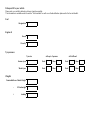
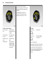
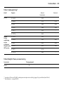
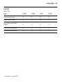
Data specific to your ve hicle
Please enter your vehicle’s data here to keep it ea sily accessible.
This information is available under the section "Technical da ta " as well as on the identification plate and in the Serv ice Booklet.
Fuel
Designati on
Engine oil
Gra de
Viscosity
Tyre pressure
Tyre si ze
wi th up to 3 persons
wi th full load
S ummer tyres
Front
Rear
Front
Rear
Winter tyres
Front
Rear
Front
Rear
Weights
Permissible Gross Vehic le Weight
–
EC k erbweight
=
Loading
Your Meriva
is an intelligent c om bina tion of forwardlooking technology, impressiv e safety ,
env ironmenta l friendliness a nd economy.
It now lies with you to drive your vehicle
safely and ensure that it perform s
perfectly. This O wner’s Manual provides
you with all the necessary information to
that end.
Make sure y our pa ssengers a re awa re
of the p ossible risk of accid ent and injury
which may result from im proper use of the
vehic le.
You m ust alway s comply w ith the sp ecific
laws of the c ountry that y ou are travelling
through. These laws ma y differ from the
inform ation in this Ow ner’s Manual.
When this Manual refers to a workshop
visit, we recommend your Vauxhall
Authorised Repairer.
All Vauxhall Authorised Repairers provide
first-class serv ice at reasona ble prices.
You will rec eive quick, reliable and
indiv idua l service.
Exp erienced mechanics, trained by
Vauxhall, work according to specific
Vauxhall instructions.
The O wner’s Ma nual should alwa ys be kept
in the vehic le: R eady to hand in the g lov e
compartment.
Make us e of the Owner’s Manual:
z The "In Brief" section will give you an
initial overv iew.
z The ta ble of contents at the beg inning
of the owner’s manual and within the
individual chapters will show y ou where
every thing is.
z Its index will help you find what you
want.
z It w ill fa miliarise you with the
sophisticated technology.
z It w ill increase y our pleasure in your
vehicle.
z It w ill help you to handle your vehic le
expertly .
The O wner’s Manual is designed to be
clearly laid-out and easily understood.
This sym bol signifies:
6 Continue read ing on next pa ge.
3 Items m arked with an asterisk are not
fitted to all v ehicles (model variants,
engine op tions, models specific to one
country, optional equipment, Genuine
Vauxhall Parts and Acc essories).
9 Warnin g
Text marked 9 Warning provides
information on risk of accident or injury.
Disregard of the instructions may lead to
injuries or endanger life.
Inform your passengers accordingly.
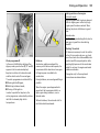
Y ellow arrows in the illustrations serve as
points of reference or indicate some action
to be performed.
Black arrows in the illustrations indicate
a reaction or a second action to be
performed.
Direc tional da ta, e.g. left or right, or front
or back, in the descriptions alway s relate to
the direction of travel.
We wish y ou many hours of p leasurab le
driving
Your Vauxhal l Tea m
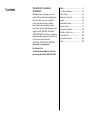
Contents
Comm itment to c ustomer
satisfaction:
Our ai m: to k eep you happy with your
vehicle. All Vauxhall Authorised Repairers
offer first-class serv ice a t competitiv e
prices. Experienced, factory-trained
technicians w ork according to factory
instructions. Y our Authorised Repa irer can
supply you with GEN UINE VAU XHALLAPPRO VED PARTS , which hav e und ergone
stringent quality and precision chec ks, and
of course useful and a ttrac tiv e
VAUXHALL-APPROVED AC CESSO RIES.
Our nam e i s your guara ntee!
For d eta ils of the
Va uxhall Authorised Rep airer Netw ork,
please r ing this number; 0845 090 2044
In Brief .. ..... .... ..... .... .... ..... .... ..... .... ..... .... .... . 2
K eys, Doors, Windows .... .... ..... .... ..... .... .. 26
S eats, Interior ..... .... .... ..... .... ..... .... ..... .... .. 43
Instrum ents, Controls ..... .... ..... .... ..... .... .. 84
Lighting ..... .... ..... .... .... ..... .... ..... .... ..... .... 105
Infotainment S ystem . ..... .... ..... .... ..... .... 114
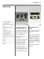
C lim ate C ontrol . .... .... ..... .... ..... .... ..... .... 117
Driving and Operation ... .... ..... .... ..... .... 132
S elf-help, Vehicle C are ... .... ..... .... ..... .... 170
Technical Data .. .... .... ..... .... ..... .... ..... .... 206
S ervice, Maintenance ..... .... ..... .... ..... .... 224
Index . .... ..... .... ..... .... .... ..... .... ..... .... ..... .... 238
2
In Brief
In Brief
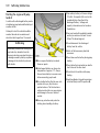
Pictu re no: 15335T.tif
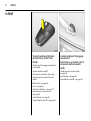
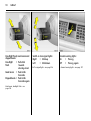
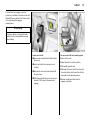
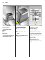
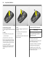
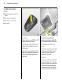
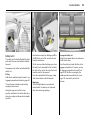
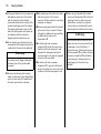
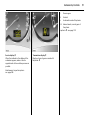
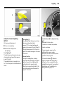
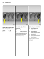
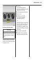
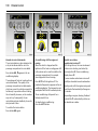
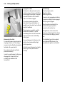
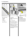
To unlock and open the doors:
Press bu tton q and lift door
handle
Picture no: 17873s.tif
All doors and the luggage compartment
are unlocked.
To unlock an d open the luggage
com partment:
Press button q on remote c ontrol
and operate button beneath
handle
Country -specific version 3:
Pressing once unlocks the driver’s door,
and pressing twice unlocks the entire
vehicle.
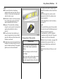
6 Radio frequency rem ote control –
see page 28,
central loc king – see pag e 30,
Vauxhall alarm system 3 – see page 34.
6 Door locks – see pag e 26,
key s – see page 26,
electronic im mobiliser – see pag e 27,
ra dio frequency rem ote control –
see p age 28,
central locking – see page 30,
Vauxhall a la rm system 3 – see pag e 34.
In Brief
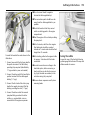
Pict ure no: 13977s.t if
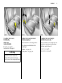
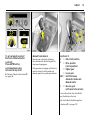
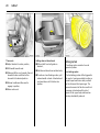
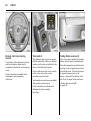
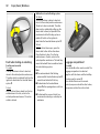
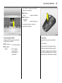
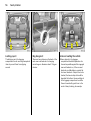
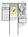
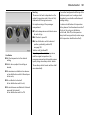
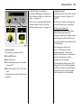
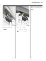
To adjust front seats:
Pull han dle,
slide seat,
release handle
6 S eats – see page 43,
seat p osition – see page 44.
9 Warning
Important: Do not sit nearer than
10 inches (25 cm ) from the steering
wheel, to permit sa fe airbag deployment.
Picture no: 13978s.tif
3
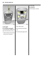
Picture no: 13979s.tif
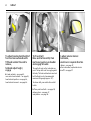
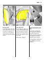
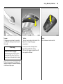
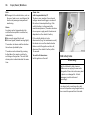
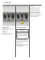
Adjust front seat backrests:
Turn handwheel
To adjust fron t seat height:
Pull front lever at side
Move backrest to suit seating position.
Do not lean on seat b ackrest while
adjusting it.
Lift lev er and relieve some weig ht from seat
to raise it or press down on seat cushion
with body weig ht to lower it.
6 Seats – see page 43,
seat position – see page 44.
6 Sea ts – see page 43,
seat position – see pag e 44.
4
In Brief
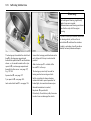
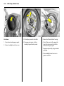
Pict ure no: 13980s.t if
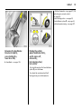
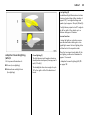
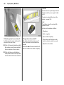
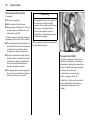
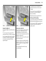
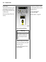
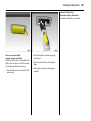
To adjust head restraint height of
front and rear ou tboard seats:
Tilt head restrain t forward to
release,
hold and adjust h eigh t,
engage
6 H ead restra ints – see pa ge 45,
rea r centre head restraint – see page 45,
head restraint position – see pag e 46,
head restraint removal – see page 46.
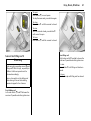
Picture no: 13982.tif
To fit seat belt:
Draw seat belt smooth ly from
inertia reel, guide over sho ulder
and engage in buckle
The seat b elt must not be twisted at any
point. The lap belt m ust lie snugly a gainst
the body . The front seat backrests must not
be tilted back too far (recomm ended
maximum tilting a ng le app rox . 25° ).
To relea se belt, press red button on belt
buckle.
6 Three-point seat belts – see page 58,
airbag system – see page 67,
seat position – see page 44.
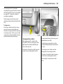
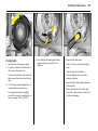
Picture no: 13985s.tif
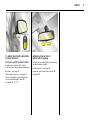
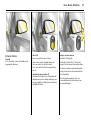
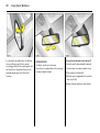
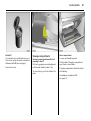
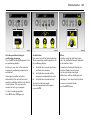
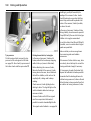
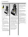
To adjust exterior mirro rs:
From inside,
swivel lever in required direc tion
6 Mirrors – see p age 37,
further inform ation, aspherical ex terior
mirror 3 – see page 37.
In Brief
Pict ure no: 16099s.t if
To adjust electrically adjustable
exterior mirrors 3:
Four-way switch in driver’s do or
Toggle roc ker switch to left or right:
Four-way switch moves appropriate mirror.
6 M irrors – see pag e 37,
fold-in ex terior mirrors – see page 37,
further information, a spheric al ex terior
mirror, hea ted exterior m irrors 3 –
see pages 12, 37, 119.
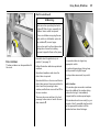
Picture no: 14300s.tif
Adjusting in terior mirror:
Swivel mirror housing
Swivel lever on underside of mirror housing
to reduce dazzle at night.
6 Interior mirror – see p age 38,
autom atic anti-dazzle interior mirror 3 –
see p age 38.
5
6
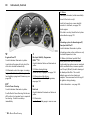
In Brief
In Brief
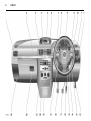
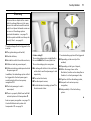
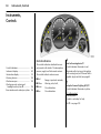
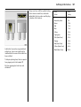
1
Page
Side air v ents ... ..... .... ..... .... .... ..... .... 118
2
Front pa ssenger’s airbag . .... ..... .... . 67
3
Infotainm ent system 3 . .... .... ..... ... 114
4
Haza rd warning lights .. .... .... .. 10, 107
LED for
Vauxhall alarm system 3 . .... ..... .... ..34
Heated seats 3 .... .... ..... .... .... ..... ... 119
5
Central information display
for time, date,
outside tem perature,
Infotainm ent system 3 . .... .... ..... .... . 92
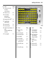
7
Pa ge
Windscreen wiper,
wind screen wash system,
headlight wash system 3 and
rear window w ash system 3 ... 11, 103
Page
18 C lutch pedal 3 ... ..... .... ..... .... ..... .... 138
Pa rk ing lights, dipped beam ... ..... 105
Courtesy light .. .... ..... .... .... ..... .... ..... 111
Instrument illumination ... ..... .... ..... 111
Fog tail lig ht .... .... ..... .... .... ..... .... ..... 107
Front fog lights 3 ..... .... .... ..... .... ..... 106
Head lig ht range adjustment .... ..... 107
20 Air conditioning system 3 ... ..... .... 117
Heated rear w indow ... ..... .... .... 12, 119
Air recirc ulation system 3 .... ..... .... 123
12
Bonnet release lev er .... .... ..... .... .... 170
23 Fusebox . ..... .... .... ..... .... ..... .... ..... .... 188
13
Remote control on steering
wheel .. ..... .... ..... .... ..... .... .... ..... .... .... 114
10
11
6
Centre air v ents .... .... ..... .... .... ..... .... 118
7
Turn signal light, headlight flash,
dipped beam, hig h beam . .... ..... .... . 10
Door-to-door lighting func tion .. ... 110
Cruise control 3 .... .... ..... .... .... ..... .... 151
14
Starter switch
with steering column lock ..... .... ..... ... 9
15
Steering wheel adjustm ent 3 ... ..... ... 9
8
Horn .... .... ..... .... ..... .... ..... .... .... ..... .... .. 11
16
Ac celera tor pedal .... .... .... ..... 138, 139
9
Instruments .. .... ..... .... ..... .... .... ..... .... . 84
17
Brake peda l ..... .... ..... .... .... ..... 138, 154
19 Ashtray .. ..... .... .... ..... .... ..... .... ..... .... .. 80
Accessory socket and
cigarette lighter . ..... .... ..... .... ..... .... .. 79
21 C lim ate c ontrol .. ..... .... ..... .... ..... .... 117
22 Glove compartment ... ..... .... ..... .... .. 81
8
In Brief
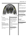
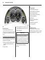
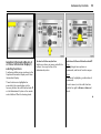
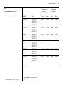
Control indicato rs
X
S ea t belt w arning dev ice 3,
see pa ge 84.
B
A dapti ve Forw ard
Light ing (AFL) 3,
see pa ges 84, 109.
I
Eng ine oi l pressure,
see page 86.
R
Turn signal l ights,
see pages 10, 86.
Brake system,
clutch system 3,
see p age 87.
O
u
C
Headli ght ma in beam,
see pages 9, 86.
Anti-lock Brak e S ystem (ABS),
see p age 156.
S
Engine oil l ev el 3,
see p age 88.
EPS
Electri c Power Steering (EPS) 3,
see p age 88.
v
Electronic Stab ility Program me
(ESP® Pl us ) 3,
see p age 149.
Y
Fuel level,
see p ages 88, 143.
y
Seat occup ancy r ecog ni tion 3,
see p ages 73, 74.
>
Front fog lights 3,
see pa ges 85, 106.
!
A
Engine elec tronics,
t ransmission el ec tronics,
i mmobi liser,
d iesel fuel filt er 3,
Easyt ronic 3,
fa ult,
see pa ges 85, 27, 147.
Preheat ing system for
diesel eng ines 3 ,
diesel part icle filter 3 ,
see page 88.
j
Easytronic 3,
start engi ne 3 ,
see page 133.
T
Easytronic 3,
wi nt er program me,
see page 135.
Z
Exha ust em issi on 3,
see pa ges 85, 147.
v
A irbag system s 3,
bel t tensi oners,
see pa ges 60, 72.
m
Crui se control 3,
see page 151.
r
Fog tail light,
see pages 87, 107.
p
Alternat or,
see page 87.
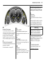
In Brief
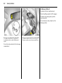
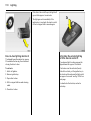
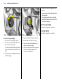
Pi cture no: 15678t.tif
Steering column lock an d ignition:
Turn key to position 1;
Move steerin g wh eel slightly
to release lock
Positions:
0 = Ignition off
1 = Steering free, ignition off
2 = Ignition on,
for diesel engines: preheating
3 = Starting
6 S tarting – see page 14,
electronic immobiliser – see page 27,
parking the vehicle – see p age 15.
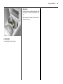
Picture no: 13981s.tif
Steering wheel adju stment 3:
Swivel lever down,
adjust height,
swivel lever up,
engage
Ad just steering wheel only when vehicle is
stationary and steering column lock is
relea sed.
6 Airbag system – see page 67.
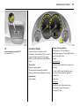
9
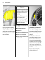
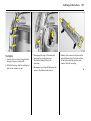
Picture no: 14727s.tif
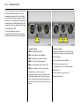
Turn ligh t switch:
7
= Off
8 = Parking lights
9 = Dipped beam
or main beam
Press button:
>
= Front fog lights 3
r
= Fog tail light
0
= Courtesy light
6 Lighting – see p age 105,
hea dlight warning dev ic e – see page 103.
10
In Brief
Pict ure no: 18475s.t if
Headlight flash, m ain beam and
dipped beam:
Headlight
= Pull stalk
flash
towards
steering wheel
Main beam
= Push stalk
fo rwards
Dipped beam = Push stalk
fo rwards again
Main beam, headlight flash – see
page 106.
Pict ure no: 14054h.tif
Picture no: 14303s.tif
Switch on turn signal lights:
Right
= Stalk up
Left
= Stalk down
Hazard warning lights:
On
= Press ¨
Off
= Press ¨ again
6 Turn signal lights – see pa ge 106.
6 Hazard warning lig hts – see p age 107.
In Brief
Pict ure no: 13991s.t if
Horn operatio n:
Press j
6 Airbag sy stem 3 – see page 67,
rem ote control on steering wheel 3 –
see page 114.
Pict ure no: 14055h.tif
Windscreen wiper:
Stalk up
§
= Off
$ = Adjustable timed interval
wipe
% = Slo w
& = Fast
6 Windscreen wiper – see p age 103,
adjustable timed interval wipe 3 –
see p age 103,
further information – see pag es 204, 233.
11
Picture no: 14056h.tif
Operating windscreen and
headlight wash systems 3:
Pull stalk towards steerin g wheel
The wiper w ill swipe for a few strok es.
The headlight wash system 3 can be
operated w hen the lights are on.
6 Windscreen wash sy stem –
see page 104,
further inform ation – see pages 204, 234.
12
In Brief
Pi cture no: 14057h.tif
Activate rear win dow wiper and
wash system:
Wiper on
= Push stalk
forwards
Wiper off
= Pull stalk
towards
steering wheel
Washer
= Push stalk fully
forwards an d
hold
6 R ear window w ash / wipe system –
see page 104,
further information – see pages 204, 235.
Picture no: 13992s.tif
Heated rear window,
heated exterio r mirrors 3:
On = Press Ü
Off = Press Ü again
6 Air conditioning – see page 117,
heated rear w indow – see page 119.
Picture no: 13993s.tif
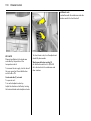
To defrost misty or icy windows:
Turn rotary knob for temperature
and airflow clo ckwise,
air distribution to V;
Air conditioning system 3:
Press button n ;
Electronic Climate Control
system 3:
Press button V
6 Climate control – see page 117,
air conditioning sy stem 3 – see page 123,
Electronic Clima te C ontrol system 3 –
see page 126.
In Brief
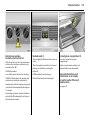
Pict ure no: 16496s.t if
To set automatic mode of
Electronic Climate Control
system 3 :
Press AUTO button,
set temperature using
left-han d ro tary kno b
6 Electronic C lim ate C ontrol system 3 –
see page 126.
Picture no: 15270s.tif
Manual transmissio n:
Reverse gear: with v ehicle stationary,
three seconds after dec lutching pull the
ring up and enga ge g ear.
If the gear d oes not engage, set the lev er in
neutra l, release the clutc h pedal and
depress again; then repeat gear selection.
Picture no: 14175s.tif
13
Easytronic 3:
N
= Idle / start positio n
o
= Drive position
(c entre position)
+
= Higher gear
= Lower gear
A/M = Switch between
Automatic mode and
Manu al mode
R
= Reverse gear
(with selec tor lever lock)
To mov e the selector lever from N to R,
press the button on the lever.
O nly start in N with footbrake applied.
6 Easytronic 3 – see page 132.
14
In Brief
To switch on the ignition, only turn the key
to position 2.
Before starting-off, check:
z Ty re pressure and tyre cond ition,
see pa ges 160, 216.
6 Electronic imm obiliser – see page 27,
diesel fuel system – see page 170,
further inform ation – see pages 138, 171.
z Engine oil level and fluid levels in engine
com partment, see pages 228 to 235.
z All windows, mirrors, exterior lighting
and num ber p la tes are free from dirt,
snow and ice and are operational.
z No ob jects are placed in front of the rear
wind ow, on the instrument panel or in
the area in which the airbag s inflate.
z Seats, seat belts and mirrors are
correctly ad justed.
z Bra ke op eration.
Picture no: 15582a.tif
To start engine:
Operate clutc h and brake,
Easytronic 3 in N,
do not accelerate,
Petrol engin es: key to 3;
Diesel engines: key to 2,
wh en control indic ator ! go es
out1) , tu rn key to 3;
release key once engine is
run ning
Before restarting or when switching off the
engine, turn k ey back to p osition 0.
1)
Prehea ting system switches o n only if ou tsid e
temp era ture is lo w.
In Brief
15
6 Further inform ation – see pages 27, 138,
radio frequency remote control –
see page 28,
central loc king sy stem – see page 30,
Vauxhall alarm system 3 – see page 34,
vehicle d ecommissioning – see page 237.
Pict ure no: 14714s.t if
Releasing th e handbrake:
Raise lever slightly,
press lock bu tto n,
lower lever fully
6 Handbrake – see pag e 155.
Pict ure no: 15758t.tif
Parking the vehic le:
Apply handbrake firmly,
switch engine off,
remove key,
loc k steering wheel,
loc k vehicle
To lock vehicle and arm the Vauxhall ala rm
sy stem 3, press button p .
To activate the mechanical anti-theft
lock ing sy stem, p ress b utton p twice.
16
In Brief
Advice wh en parking:
z Do not p ark the v ehicle on flam mable
surfaces as combustion could occur due
to the high ex ha ust temperatures.
z Alwa ys apply the handbrake firmly.
Ap ply the ha ndb ra ke as firmly as
possible on uphill or downhill slopes. To
reduce operating forces, a pply
footbrake at the sa me tim e.
z Close windows, slid ing roof 3 and tilting
roof 3 .
z With manual transmission, select first
gear or reverse gea r. With Easytronic 3,
move selector lever to c entre p osition
before switching ignition off.
z O n vehicles with Easytronic 3, c ontrol
indicator R flashes for a few second s
after the ignition is switched off if the
handbrake has not been applied.
z Turn steering wheel until lock is felt to
eng age (anti-theft protection) after first
withdrawing the ignition key.
z The engine cooling fans may run a fter
the engine has been switched off,
see page 227.
6 Further information –
see p ages 235, 237.
In Brief
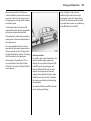
17
That was the most important
information for your first drive
in your Meriva in brief.
The other pages o f this chapter
con tain a description of some
interesting fun ction s in your
vehicle.
The remain ing ch apters of the
Owner’s Manual contain
impo rtant information on
operatio n, safety and
maintenance as well as a
com plete in dex.
18
In Brief
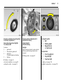
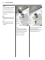
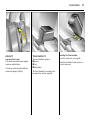
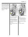
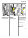
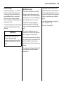
Flexible Seat System (FlexSpace)
The rear row of seats in your vehicle offers
three seats or, with the centre seat lowered,
two seats with more seating space. The
outboard seats can be lowered to obtain a
lev el loading surface.
Picture no: 14178s.tif
Picture no: 14179s.tif
Move rear outboa rd sea ts
z Pull handle under seat,
Ad just or fold b ackrest of outb oard seats
z Pull handle on outb oa rd side of seat,
z Slide seat,
z Guid e b ackrest into the relevant position,
z Release handle and a llow seat to
eng age in p osition.
z Release handle and allow seat to audibly
engage in position.
The back rests must not be in the rearm ost
position when the seats a re moved ba ck, in
order to prevent d amage.
In Brief
19
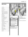
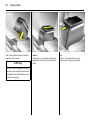
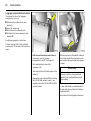
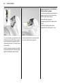
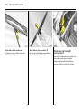
The b ackrest can engage in several
positions. In ad dition, the back rest can be
folded all the w ay down to the sea t cushion
when extend ing the luggage
compartment.
9 Warning
To prevent injuries, a lways hold seat
backrest firmly and guide downwards
when folding .
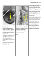
Picture no: 14728s.tif
Picture no: 14729s.tif
Low er c entr e seat
z House centre seat belt in the belt reta iner
in the roof,
Two r ear seat s w ith more seating sp ace
z Lower centre seat,
z Insert seat belts into recesses in seat
cushion,
z Pull handle beneath seat.
z Adjust back rest to centre position,
z Slide centre rea r seat hea d restraint all
the way d ow n,
z Slide seat all the way back , then towards
the centre of the v ehicle and then further
rearwards to the desired position,
z Pull release handle at rear of centre seat
back rest. Tilt back rest forwa rd s a nd
eng age.
z Release handle and allow seat to
engage in position.
20
In Brief
Pict ure no: 14730s.t if
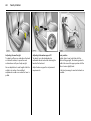
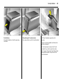
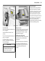
Three seats
z Ad just back rest to centre position,
z Pull handle beneath seat.
z Slide seat all the way forwards, then out
towa rd s the door and then further
forwards to the desired position.
z Release handle and allow seat to
engage in position,
z Raise centre seat.
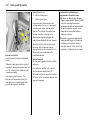
Picture no: 14716s.tif
Picture no: 14125s.tif
Fold ing down out board seats
z Pull seat belt from belt guide on
back rest,
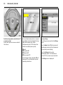
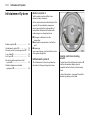
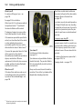
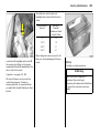
Airbag system
z Fold down outb oa rd rear sea t bac krests,
Front airb ag system
The front airbag system will be triggered in
the event of a serious a ccident involving a
fronta l impact a nd form s safety cushions
for the d riv er and front passenger. The
forward m ov ement of the driver and front
passenger is c hecked and the risk of
injuries to the upper body and head are
thereby substantially reduced.
z To achieve a lev el loading surfa ce, pull
release handle on back of backrest and
push seat down until it latches into
position.
The airbag system consists of sev eral
sepa ra te systems.
In Brief
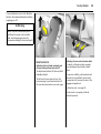
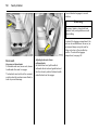
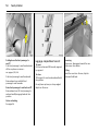
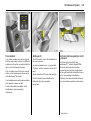
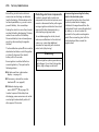
Pict ure no: 14742s.t if
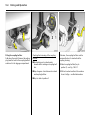
Sid e a irbag system 3
The side airb ag is trigg ered in the ev ent of
a side-on collision to form a safety cushion
for the driver or front passeng er in the
respective door area. This substantially
red uces the risk of injury to the upper body
and pelvis.
Picture no: 14127s.tif
Curtai n airbag system 3
The curtain airbag system triggers in case
of a side-on collision and provides a safety
barrier in the head a rea on the respective
side of the v ehicle. This reduces the risk of
injury to the head considerably in case of a
side-on collision.
6 Airbag system s – see page 67.
21
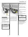
Picture no: 14287j.tif
Active head restraints 3 on front
seats
In the ev ent of a rear-end im pact, the
active head restraints a utomatica lly tilt
forward a little. The head is m ore
effectively supported b y the head restraint
and the danger of injuries caused by
whiplash in the neck area is reduced.
Active head restraints are identified by the
lettering ACTI VE on the head restraint
guide sleev es.
22
In Brief
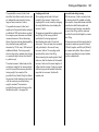
Pict ure no: 14304s.t if
Picture no: 14315s.tif
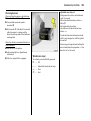
3
The Trav el Assistant contains:
z Arm rest,
z Tray ,
z Drink holders.
Di sm antling the Tr avel Assistant
z Press lower button on the Travel
Assistant,
The Trav el Assistant is mounted on the
lowered centre seat (see pag e 19).
z There is a ca rry ing handle on the b ack to
facilitate tra nsport.
Travel Assistant
z Pull Travel Assistant upwards out of
rec esses,
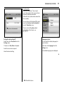
Picture no: 15593t.tif
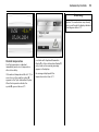
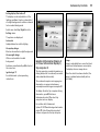
Operating m enu s in the
information display 3
Menu op tions are selected using menus
and using the b uttons / four-way button or
the multi-function knob of the I nfotainment
system 3 or the buttons 3 on the steering
wheel. The respectiv e m enu options are
show n on the display.
S elec tion using four-way button:
press four-w ay button at top, bottom , left
or right.
In Brief
Ü
Board Computer
BC 1
1
8
Pi cture no: 15559t.tif
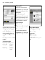
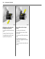
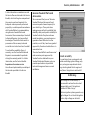
Selection using multi-function knob 3:
Rotate and press multi-function knob.
To exit a m enu, turn the multi-function
knob left or right to Ret urn or Main and
select.
Picture no: 14034s.tif
To select w ith steering wheel buttons:
Select menu options via the menus and the
buttons.
6 Information disp la y – see p age 92.
19,5° 19:36
All values
BC 2
Timer
23
257.0
40
7.0
Ø 31.0
Ø
miles
mph
gals
mpg
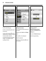
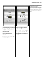
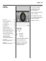
Picture no: 16719t.tif
Trip computer
3
The trip comp uters provide informa tion on
driving da ta , which is continually recorded
and evaluated electronica lly .
Functions:
z Range,
z Instantaneous consumption,
z Distance travelled,
z Average speed,
z Effective consum ption,
z Average consum ption,
z Stop watch.
6 Trip computer – see page 99.
24
In Brief
Pict ure no: 14034s.t if
Remote control on steering
wheel 3
The functions of the Infotainment sy stem
and the information display can be
opera ted with the buttons on the steering
wheel.
Further information is available in the
Infotainm ent system operating
instructions.
Picture no: 14035s.tif
Twin Audio
3
Tw in Audio p rov id es rear seat occupants
with the opportunity to listen to a different
audio source tha n the one selected by the
driver on the Infotainment sy stem.
Only a n audio source tha t is not currently
active on the radio system can be
controlled using Twin Audio.
Tw o headp hone connections are a vailable,
with separate volum e c ontrols.
Further inform ation is av ailable in the
Infotainment sy stem opera ting
instructions.
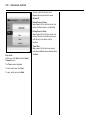
Picture no: 14779s.tif
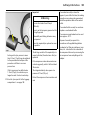
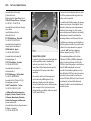
Parkin g distance sensors 3
When rev erse gear is selected, the p arking
distance sensors switch on automatically .
If the v ehicle approaches an obstacle when
reversing, a series of signals can be hea rd
in the vehicle interior. The interv al b etween
the signals becomes shorter as the
distance is reduced. If the distance is less
than 30 cm, the sig nal will be continuous.
6 Parking dista nce sensors 3 –
see page 153.
In Brief
25
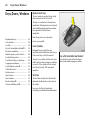
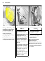
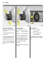
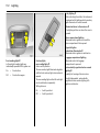
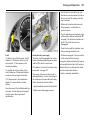
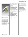
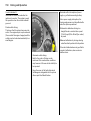
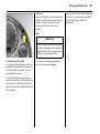
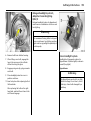
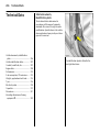
Turn lig hting (2)
An add itional light illuminates at certain
steering wheel setting s (after rota tion of
app rox . 90° ), turn signal settings and
speeds (up to approx. 25 m ph (40 km /h)).
The lig ht beam projects at a 90° angle to
the left or right of the v ehicle up to a
distance of a pprox. 30 metres.
Reverse function
Turning the lights on, selecting reverse
gear selected a nd sw itching on a turn
signal light causes the turn lighting to be
switched on for the respective side.
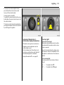
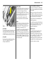
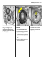
Pictu re no: 15209j.tif
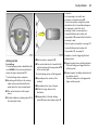
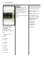
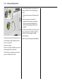
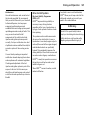
Adaptive Forward Lighting
(AFL) 3
AFL im prov es illumina tion of:
z Curves (curve lighting),
z Intersections and tig ht turns
(turn lighting ).
Picture no:
Curve lig hting (1)
The light beam pivots based on steering
wheel position and speed (from ap prox . 6
mph (10 k m/h)).
The head lig hts shine at an a ngle of up to
15° to the right or left of the direction of
tra vel.
When the turn signal is sw itc hed off, the
turn lighting continues to illuminate for
app rox . 15 second s.
6 Adaptive Forward Lighting (AFL) 3 –
see page 109.
26
Keys, Doors, Windows
Keys, Doors, Windows
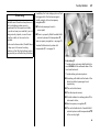
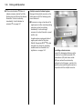
Replacement keys
The key number is specified in the vehic le
docum ents and in the C ar Pass 3.
The key is a c onstituent of the electronic
immobiliser. Ordering keys from a Vauxhall
Authorised Repairer g uarantees problem free op eration of the electronic
immobiliser.
Replacem ent keys ... ..... .... ..... .... .... ..... .
Loc k cylinders . ..... .... ..... .... ..... .... .... ..... .
Ca r Pass... .... .... ..... .... ..... .... ..... .... .... ..... .
Key with retractable key blade 3 ..... .
Electronic immobiliser... .... ..... .... .... ..... .
Radio frequency remote control .. ..... .
Central locking system . .... ..... .... .... ..... .
Fault when locking or unlocking... ..... .
Lug gage compartment .... ..... .... .... ..... .
Vauxhall alarm system 3. ..... .... .... ..... .
Child safety locks . .... ..... .... ..... .... .... ..... .
Ex terior mirrors..... .... ..... .... ..... .... .... ..... .
Interior mirror .. ..... .... ..... .... ..... .... .... ..... .
Door windows . ..... .... ..... .... ..... .... .... ..... .
Electric windows 3 ... ..... .... ..... .... .... ..... .
Sunroof and tilting roof 3 ..... .... .... ..... .
26
26
26
26
27
28
30
32
32
34
36
37
38
39
39
41
Keep the sp are k ey in a safe plac e.
Locks, see pa ge 204.
Loc k cylinders
Designed to free-wheel if they are
forcefully rotated without the correct k ey or
if the correct key is not fully inserted.
To reset, turn cy linder with the c orrect key
until its slot is vertica l, remove key and then
re-insert it. If the cylinder still free-wheels,
turn the key through 180° and rep eat
op eration.
Car Pass
The Ca r Pass contains a ll of the vehicle’s
data and should therefore not be k ept in
the vehicle.
Have your Ca r Pa ss to hand when
consulting a Vaux hall Authorised Repairer.
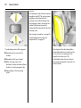
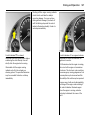
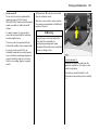
Picture no: 15760t.tif
Key with retractable key blade
Press button to extend. Press button to
retrac t and audibly engage key b la de.
3
Keys, D oors, Windo ws
27
If control indicator A illum inates after the
eng ine is started, there is a fault in the
eng ine electronic s or transmission
electronics 3, (see pages 85, 137, 147), or
there is water in the diesel fuel filter 3,
(see page 230).
Not e
The immobiliser does not lock the doors.
Therefore, alwa ys lock the vehicle before
leaving it unattended and enable Vauxhall
alarm sy stem 3 . See p age 34.
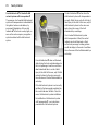
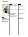
Pi cture no: 15761t.tif
Electronic immo biliser
Using a transponder housed in the key , the
system checks whether the vehicle may be
started using the key that has been
inserted. If the k ey is recognised as
"authorised" the engine can be started.
The electronic imm ob iliser activates
automatically when the k ey is removed
from the starter switch.
The c od e number of the electronic
immobiliser is giv en in the C ar Pass.
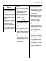
Picture no: 17880s.tif
Control i nd icator for imm obiliser A
Control indica tor A illuminates briefly
when the ig nition is sw itched on.
If the control indicator flashes w hen the
ignition is on, there is a fault in the sy stem;
the engine cannot be started. S witc h off
the ignition and then rep eat the start
attempt.
If the control indicator A continues to
flash, try to start the engine using the spare
key and conta ct a workshop for assistance.
28
Keys, Doors, Windows
Radio frequenc y remote control
Dep ending on equipment level, the vehicle
comes equipped with one of the remote
controls illustrated on this page.
The rad io frequency remote control is
integrated in the key .
Used to op erate:
z Central locking system ,
z Mechanical anti-theft locking system ,
z Vauxhall ala rm system 3 .
In vehicles with electric windows in all
doors 3, the rem ote control can be used to
closed the windows.
Pict ure no: 15330t.tif
Picture no: 15331t.tif
The remote control has a ra nge of approx.
5 metres. This range can be affected by
outside influences. Aim the remote control
at the v ehicle to op erate.
C entra l lock ing system,
see page 30.
Handle the rem ote control with care,
protect it from m oisture and high
temperatures and avoid unnecessary
op eration.
Vauxhall ala rm system 3,
see page 34.
The haz ard warning lights flash to indicate
that the rem ote control is op erational.
Mechanic al anti -theft locki ng system,
see page 28.
Electric w indows 3 ,
see page 39.
Keys, D oors, Windo ws
Fault
If the central locking system cannot be
opera ted with the remote control, it m ay b e
due to the following :
K ey with fix ed blade,
see Fig. 15331 T on previous page.
Hav e the workshop chang e the battery .
I n t he event of a funct ionality prob lem or
ba ttery r epl acement, synchroni se the
remot e cont rol.
After c hanging the battery , unlock the
door using the key in the driver’ s lock
cy linder, see page 32. The remote control is
synchronised by inserting the key in the
starter switch.
z The range of the rem ote control has
been ex ceeded.
z Remote control b attery v olta ge is too
low. Battery replac ement - see next
column.
z If the remote control is frequently and
repeatedly operated outside the
recep tion range of the v ehicle (e.g. too
far from vehicle), the remote control will
no longer be recognised . Remote c ontrol
synchronisation, see end colum n.
z If the centra l loc king sy stem is
ov erloaded as a result of repeated
op eration at short interv als. The power
supply is c ut off for a b rief period.
z Interference from higher-power radio
waves from other sources.
To elim inate the cause of a fault, we
recom mend contacting a workshop for
assistance.
O pen driver’s door with key, see pa ge 32.
29
Pict ure no: 15332t.tif
Rem ote control b attery rep lacement
Replace the battery as soon as the range
of the rem ote control becom es reduced.
Key with retrac ta ble k ey blade,
see Fig. 15330 T on previous pa ge.
Extend key, see pa ge 26. O pen remote
control. Replace battery - b attery type, see
page 218 - noting installation position.
Close remote control.
Make sure that you dispose of old batteries
in accordance with environmental
protection regulations.
30
Keys, Doors, Windows
Pi cture no: 15335t.tif
Cen tral locking system
For doors, luggag e compartment and tank
flap.
Pict ure no: 15333t.tif
To lock
Close doors, luggage compartment and
tank flap.
To unlock
Press button q on the remote control
Press button p on the rem ote control
– or, from the inside –
press lock button on driv er’s door when the
doors are closed.
pull up lock button on driver’s door.
When the mechanical anti-theft locking
system is enabled, the doors cannot be
unlock ed by pulling up the lock buttons.
Country-specific v ersion 3 :
Pressing once unlock s the driver’s door,
and pressing twice unlock s the entire
vehic le.
– or, from the inside –
Picture no: 15334t.tif
Mechanic al anti -theft locki ng system
9 Warnin g
Do not use the system if there are people
in the vehicle! The doors cannot b e
unlocked from inside.
All the doors must be closed.
Press the p button on the rem ote control
within 10 seconds of locking.
Lock buttons on all doors are positioned
such tha t doors ca nnot be opened.
If the ignition wa s on, the driver’s door
must be opened and closed once so that
the vehicle can be secured .
Keys, D oors, Windo ws
Note
z To prevent the driver from being
inad vertently locked out, the button on
the driver’s door cannot b e d epressed
when the d oor is open.
O n vehicles with electric windows in all
doors 3, the windows can be closed from
outside:
Hold button p on the remote c ontrol
depressed until all of the wind ow s hav e
closed completely.
z If the driv er’s door is not closed properly ,
the central lock ing sy stem will unlock
again immediately after locking.
Further information on electric windows,
see page 39.
Fault
If the central locking cannot be operated,
this can be for one of the following reasons:
z Ap prox . 30 seconds after unloc king
using the remote control, the doors lock
again automatically if no door is
op ened.
z To lock the doors from inside (e. g. to
prevent unwa nted entry from outside),
press lock button on d riv er’s door when
the doors are closed.
z Locked doors unlock automatically if an
accident of a certain sev erity occurs (to
permit outsid e assistance). Prerequisite:
Ignition must not be switched off.
31
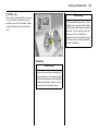
Picture no: 17899s.tif
Closing w indows 3 from outside
9 Warning
Exercise care when operating electric
windows. Risk of injury , especially for
children.
Vehicle passeng ers must be informed
accordingly.
K eep a close watch on the windows when
closing them. Ensure that nothing
becomes trapped in them as they move.
z If the central locking system is
overloaded as a result of repeated
operation at short intervals. The power
supply is cut off for a brief period .
z Defec tiv e fuse in fusebox, see page 188.
To elimina te the cause of a fault, w e
recommend contac ting a workshop for
assistance.
O perate driver’s door with key , see nex t
pag e.
32
Keys, Doors, Windows
Malfuncti on i n cent ral lock ing syst em
To unlock
Turn key c lock wise in driver’s door lock,
return to the vertical position and remove.
The driver’s door is unlocked. The other
doors can b e unlocked by pulling up the
interior lock buttons (not possible if the
mechanical a nti-theft locking system is
enabled). Switch on the ignition to
deactiv ate the Vaux ha ll alarm system 3.
Pict ure no: 17881s.t if
Fault when lo cking or u nloc king
Fault in remot e c ontrol
To unlock
Turn key clockwise in d riv er’s door lock,
return to the v ertical position and rem ov e.
The entire vehicle is unloc ked. Sw itc h on the
ignition to deactiv ate the Vaux hall alarm
system 3.
To lock
With the driver’s door closed, turn the k ey
anticlockwise in the lock, return to the
vertic al position and remove. The entire
vehic le is locked.
To lock
With the driver’s door open, press the
interior lock button of the other doors.
Close the driver’s door. Turn the key
anticlock wise in the lock, return to the
vertical position and remove. The tank flap
cannot be locked if there is a ma lfunction in
the central lock ing sy stem.
Note
z The mechanical a nti-theft locking
system and the Vauxhall alarm system 3
cannot be activated with the key .
z To deactivate the Vauxhall alarm
system 3 after opening a d oor, switch on
the ig nition.
z To elim ina te the cause of a fault, we
rec om mend contacting a workshop for
assistance.
Picture no: 15335t.tif
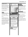
Luggage com partment
To unlock
Press button q on the remote control. The
luggage compa rtm ent is unlock ed
together with the d oors and the tank flap.
C ountry-specific v ersion 3:
Press button q twice on the remote
control; one press unlocks the driver’s door,
two presses unlocks the entire vehicle.
Keys, D oors, Windo ws
Pict ure no: 17873s.t if
To open
The lugga ge com partment is opened by
opera ting the unlock ing button b eneath
the handle.
9 Warning
Do not d riv e with the luggage
com partment open or ajar, e.g. when
transporting bulky objects, since toxic
exhaust gas c ould penetrate the interior.
Fitting of a ccessories on the tailgate will
increase its weight. If it becomes too heavy ,
it will then not stay op en.
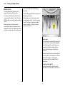
Picture no: 17882s.tif
To close
There a re two handles on the inside of the
tailg ate for closing the luggage
compartment.
Do not operate the unloc king button
beneath the handle when closing.
Otherwise the luggage compa rtm ent will
once again b e unlocked .
Picture no: 15333t.tif
To lock
Press button p on remote control.
33
34
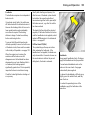
Keys, Doors, Windows
Vauxhall alarm system
3
Monitors:
z The doors, lug gage compartment,
bonnet,
z The passenger c om partment,
z Vehicle tilt, e.g. if it is raised,
z The ignition.
Pict ure no: 15334t.tif
Picture no: 11575s.tif
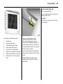
To activ ate
All doors, windows, sunroof 3, tilting roof 3
and the bonnet must b e closed.
Act ivat ion without monitoring of
pa ssenger comp artment or vehicle tilt
E.g., if anim als a re to be left in the v ehicle.
Press button p on the rem ote control to
activate the Vauxhall alarm system and
lock the d oors.
1. Close luggage comp artm ent and
bonnet.
If the ignition wa s switched on, the driver’s
door must b e opened a nd closed once so
that the anti-theft alarm system can be
switched on.
2. Press button in front of the c ourtesy light
(with ig nition off); LED in the haz ard
warning light button flashes for a
maxim um of 10 seconds.
3. Close doors.
4. Switch on anti-theft alarm system . LED
illuminates. After approx . 10 second s,
the anti-theft alarm sy stem is activated
without monitoring of the passenger
compartment or vehicle tilt. The LED
fla shes until the system is switched off.
Keys, D oors, Windo ws
35
After the first 10 seconds of anti-theft
alarm system activation:
z LED flashes
slow ly
= Sy stem switched on,
z LED illuminates
for approx.
1 second
= Switch-off function.
If a system fa ult occ urs, contact a
work shop for assistance.
Pict ure no: 14046s.t if
Light emit ting d iode (LED)
During the first 10 seconds of anti-theft
alarm system activation:
z LED comes on =
z LED flashes
quick ly
=
Test, switc h-on delay,
Door, lugg age
com partment or
bonnet open, or
system fault.
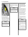
Picture no: 15335t.tif
To deact ivat e
Press button q on remote control unit
– or –
turn on ignition.
If there is a fault in the remote control,
unlock vehicle as describ ed on p age 32.
If the alarm is triggered w hen the driv er’s
door is opened, d eactivate the anti-theft
alarm sy stem by sw itc hing on the ignition.
36
Keys, Doors, Windows
Note
z Changes to the vehicle interior, such as
the use of seat c ov ers, could impa ir the
function of passeng er comp artm ent
monitoring.
Alar m
An alarm c an be trigg ered when the
anti-theft alarm system is switched on,
indicated by:
z An a coustic signal (horn) and
z A visual signal (hazard warning lig hts).
The number of alarms and the duration
thereof are stipulated by law.
The a la rm can be silenced by pressing
button q on the remote control or b y
switching on the ignition. The anti-theft
alarm system is dea ctiv ated at the same
time.
Alarm sir en
with int eg rated ba ttery 3
The alarm siren monitors the on-board
voltage network and triggers an alarm if
this network is m anip ulated (e.g. if the
vehicle’s battery is d isconnected by
unauthorised persons). The alarm siren has
its own power sup ply and is therefore not
dependent on the vehicle’s battery.
If the v ehicle’s ba ttery is to be
disconnected (e. g. for maintenance work),
the alarm siren must be deactivated as
follows: switch the ignition on then off,
disconnect the vehic le’s battery within
15 seconds.
To sw itch off al arm siren:
Switch ignition on then off.
Picture no: 16102s.tif
Child safety locks
9 Warnin g
Use the child safety lock whenever
child ren are occupying the rear seats.
Disregard of these instruc tions may lead
to injuries or endanger life. Vehicle
passeng ers must be informed
accordingly.
Turn rota ry knob in each rea r door loc k
from v ertical position using the ignition key:
Door cannot be opened from the inside.
Keys, D oors, Windo ws
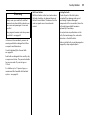
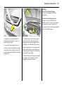
Pict ure no: 13985s.t if
Exterio r mirrors
Manual
From the inside, move the handle in the
appropriate direction.
Picture no: 16099s.tif
37
Picture no: 15279s.tif
Electri c 3
Four-way switch in driver’s door.
Sw ing-in exter ior mirror s
Manually: Press lightly.
Move rock er switch located above the
four-way switch to the left or right:
Four-way switch controls c orresponding
mirror.
Electrically: Press b utton. The mirrors
swing-in to their respective end positions.
Asp heri cal ext eri or mirror 3
Increases the field of view. Estima ting the
distance away from vehicles following you
is only possible to a limited extent because
of slight distortion.
If a mirror has b een manually adjusted,
swing-in both mirrors by hand and then
press the button.
After electrical op eration, there is a
6-second delay before the mirrors can
be opera ted a gain.
38
Keys, Doors, Windows
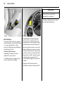
Pict ure no: 14138s.t if
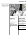
For the safety of pedestrians, the exterior
mirrors will swing out of their normal
mounting p osition if they are bumped with
sufficient force. Reposition the m irror by
apply ing slight pressure to the mirror
housing.
Picture no: 14300s.tif
In terior mirror
To adjust, swivel mirror housing.
Swivel lever on underside of mirror housing
to reduce dazzle at night.
Picture no: 13984s.tif
Autom atic anti-da zzle interior mi rror 3
Dazz le at night is automatically reduced.
The mirror does not reduce dazzle when:
z The ignition is switched off,
z Reverse gear is engag ed or the selec tor
lever is set to R,
z Interior lighting ha s b een switched on.
Keys, D oors, Windo ws
39
Electric win dows 3
9 Warning
Take care when operating the electric
windows 3. Risk of injury, espec ia lly for
children. Inform vehicle occupants.
If there are children occupy ing the rea r
seats, switch on child safety sy stem for
rea r windows 3, see nex t page.
K eep a close watch on the windows when
closing them. Ensure that nothing
becomes trapped in them as they move.
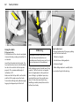
Pict ure no: 14137s.t if
Doo r win dows
Operable when the ig nition key is in
position 1 (see p age 9).
The d oor w indows can be operated with
the c ra nk .
Button illumination indica tes operational
readiness.
Operational readiness ends when the
driver’s door is opened.
Operated with two or four cross switches in
driver’s door armrest: top cross switc hes for
driver’s and front passenger’ s d oor
wind ow s, and bottom cross switches 3 for
the rea r windows.
There a re also cross switches in the front
passenger’s door arm rest and in the rear
door armrests 3.
Picture no: 14804s.tif
To operate window in stages, tap
app ropriate switch.
For autom atic opening or closing, keep
switch pressed for slightly longer.
To stop window mov ement, tap switch
aga in.
Sa fet y functi on
If the window glass encounters resistance
abov e the middle of the window d uring
automatic c losing, it is imm ediately
stopped and the w indow opened again.
If the windows do not move easily (e.g. on
acc ount of frost), repeatedly tap the switch
for the a ppropriate window until the
window has been closed in stages.
40
Keys, Doors, Windows
O verload
If the windows a re repeatedly operated at
short intervals, the power sup ply is briefly
cut off.
The sy stem is protected by fuses in the
fusebox, see page 186.
Fault
The wind ow s c annot be automatically
opened or closed.
Activate electric windows as follows:
1. Close doors.
2. Switch on ignition.
Pict ure no: 14140s.t if
Chil d safety syst em for rear wi nd ows 3
Switch b etween the rock er switches in the
armrest on the driver’ s d oor:
z To the left (red control indicator visible):
Rear windows cannot be operated with
the rocker buttons in the rear doors,
z To the right (green control indicator
visible): Rear windows can be operated
with the rocker b uttons in the rear doors.
Picture no: 17899s.tif
Closing w indows from out si de 3
On vehicles with electric windows in all
doors, the windows can be closed from
outside:
Hold button p on the remote control until
all of the windows have closed com pletely .
3. Open window completely .
4. Close window a nd hold down rocker
switch for at least another 5 seconds.
5. Repeat for ea ch window.
Keys, D oors, Windo ws
41
To op en:
Press button l , sunroof opens.
To stop the movement, press button ag ain.
To close
Press button \ until the sunroof is closed.
To ra ise
With the sunroof closed , press button \
until sunroof is open.
To low er
Press button l until the sunroof is closed.
Pict ure no: 14251s.t if
Sunroo f and tilting roof
3
9 Warning
Ta ke care when opera ting sunroof 3 and
tilting roof 3. Risk of injury , especially for
children. Vehicle oc cup ants must be
informed accordingly.
Keep a close watch on the sliding roof
when closing it. Ensure that nothing
becomes trapped in it as it moves.
Front sliding roof
Left rocker sw itch l a nd \ between the
sunvisors. O perable when the ignition is on.
Picture no: 14143s.tif
Rear t ilting roof
Right rocker switch \ and w b etween the
sunv isors. O pera ble when the ignition is on.
To raise
Press button \ until tilting roof has been
raised.
To lower
Press b utton w until tilting roof has closed.
42
Keys, Doors, Windows
Sunshade
To reduce the sunlight in the vehicle interior
with the sliding roof closed or raised.
O pen or close sunshade as req uired.
When the sunroof is opened, the sunshade
is also op ened.
Note
z If the top of the roof is wet, raise roof,
allow water to run off and then op en
roof.
z When using a roof rack, check the
clearance of the sunroof, to av oid
damage.
Picture no: 14802s.tif
Fault
If the electric d riv e fails, the sy stem is
protected by a fuse in the fusebox – see
page 186. Until the fault is rem edied,
op erate the sunroof as follow s:
Push drive cover backwards.
Picture no: 14803s.tif
Press the sprung central pa rt of the drive
shaft in as fa r as possible with a
screwd riv er 3 and turn the driveshaft until
the sunroof or tilting roof is closed.
Seats, Interior
43
Seats, Interior
Front sea ts .. .... ..... .... ..... .... ..... .... .... ..... .
Head restraints .... .... ..... .... ..... .... .... ..... .
Armrest 3 .... .... ..... .... ..... .... ..... .... .... ..... .
Travel Assistant 3 ... ..... .... ..... .... .... ..... .
Rear seats.... .... ..... .... ..... .... ..... .... .... ..... .
Flexible Seat S ystem (Flex Space). ..... .
Lug gage compartment extension .... .
Lug gage compartment cover 3... ..... .
Safety net 3 .... ..... .... ..... .... ..... .... .... ..... .
Lashing eyes 3 .... .... ..... .... ..... .... .... ..... .
Bag hangers 3 ..... .... ..... .... ..... .... .... ..... .
Notes on loading the vehic le .... .... ..... .
Three-stage safety sy stem.... .... .... ..... .
Three-point seat belts .. .... ..... .... .... ..... .
Belt tensioners. ..... .... ..... .... ..... .... .... ..... .
Using the belts ..... .... ..... .... ..... .... .... ..... .
Mounting brackets 3 for ISO -FIX child
restra int system s ... ..... .... ..... .... .... ..... .
Child restraint systems 3 . ..... .... .... ..... .
Airbag system . ..... .... ..... .... ..... .... .... ..... .
Ciga rette lig hter 3 ... ..... .... ..... .... .... ..... .
Accessory sockets 3 ..... .... ..... .... .... ..... .
Ashtray s .. .... .... ..... .... ..... .... ..... .... .... ..... .
Fold away ta bles 3 .. ..... .... ..... .... .... ..... .
Stowage comp artm ents... ..... .... .... ..... .
Coin holder .. .... ..... .... ..... .... ..... .... .... ..... .
Sunvisors.. .... .... ..... .... ..... .... ..... .... .... ..... .
43
45
47
47
50
51
52
54
55
56
56
56
58
58
60
62
64
65
67
79
79
80
82
81
83
83
Picture no: 13977s.tif
Front seats
9 Warning
Imp ortant: Do not sit nea rer than
10 inches (25 cm) from the steering
wheel, to perm it safe airba g deploy ment.
Never adjust the seat while driving.
It could mov e in an uncontrolled manner
when the handle is pulled.
Adjust seat longi tudinally
To adjust, p ull the handle on the front seat,
slide the seat and release the handle.
Picture no: 13978s.tif
Ad just ing the bac krest
To adjust, turn hand wheel on outboard
side of seat while releasing the load on the
bac krest.
Move seat backrest to suit seating position.
44
Seats, Interior
Pict ure no: 13979s.t if
Picture no: 16098s.tif
Adj usti ng the seat hei ght
To adjust, pull lever up and reliev e the load
on the sea t cushion, or press the seat
cushion down with y our b od y weight.
Adjusting t he lum bar supp ort 3
To adjust, turn side handw heel on
outboard side of seat while relieving the
loa d on the ba ckrest.
Never adjust d riv er’s seat height while the
vehic le is in motion. Uncontrolled
adjustm ents could occur when the lever is
pulled.
Ad just lumbar support to suit p ersonal
requirements.
Picture no: 14100s.tif
Seat position
Adjust driver’s sea t such that with the
driver sitting upright, the steering w heel is
held in the area of its upper spokes with the
driver’s arms slig htly bent.
Push front passeng er’s seat as far bac k as
possible.
Seats, Interior
45
The seat backrests must not be tilted too
far back . Recommend ed m aximum tilting
angle approx. 25°.
9 Warning
Failure to ob serve these descriptions
could lead to injuries which could be
fata l. Vehicle p assengers must b e
informed accordingly b efore starting-off.
Picture no: 13980s.tif
Head restraints
Adjusting t he front head rest raints and
the rea r outboard head rest raints 3
To adjust head restraint, tilt forward, hold
and adjust height.
To fold ov er the rear seats or lower the
front passenger’ s seat head restra int a ll
the way down and remove, see next page.
Picture no: 14102s.tif
Ad just ing the rear centre head restraint
To adjust, pull hea d restraint upwards,
press spring s a nd push head restraint
down.
To improve visibility, push hea d restraint
down as far a s p ossible if centre sea t is
unoccupied or to increase the size of the
luggage compa rtm ent.
Fold centre seat – see page 53.
If c entre sea t is occ upied, pull head
restraint upwards.
46
Seats, Interior
Pict ure no: 14101s.t if
Head restrai nt position
The midd le of the head restraint should be
at eye lev el. I f this is not possible for
extremely tall persons, set to highest
position, and set to lowest position for
small persons.
9 Warning
Failure to ob serve the descriptions can
lead to injuries which could be fatal.
Vehicle passengers must be informed
according ly before moving a way.
Picture no: 14287j.tif
Activ e head restra ints 3
In the event of a rear-end impact, the
active head restraints automatically tilt
forward a little. The hea d is more
effectively sup ported by the head restraint
and the da ng er of injuries caused by
whip la sh in the neck area is reduced.
Ac tiv e hea d restra ints are identified by the
lettering AC TIVE on the head restra int
guid e sleeves.
Picture no: 11581s.tif
Remov ing the head restraint s
Press and release the two catches.
Pull and remove the hea d restraint.
Not e
O nly approved objects or com ponents
should be attached to the head restraint of
the unoccupied front passenger’s seat.
Seats, Interior
Pict ure no: 14738s.t if
Armrest 3
Arm rest a t driv er ’s seat
Push raised armrest back wards against
resista nce and fold down.
The a rm rest can be moved to different
positions in stag es by lifting it.
Picture no: 14304s.tif
Travel Assistant
3
The Travel Assista nt c ontains:
z Armrest,
z Tray,
z Drink holders.
The Travel Assista nt is mounted on the
low ered centre seat (see page 53).
47
Picture no: 14310s.tif
I nsta lling The Travel Assistant
Lower the centre seat – see page 53.
Insert Travel Assistant in rear recesses on
bac k of centre seat.
48
Seats, Interior
Pict ure no: 14311s.t if
Fold Travel Assistant down a nd audibly
enga ge in front recesses.
9 Warning
If it is not c orrectly eng aged, the Trav el
Assistant can b e propelled forward with
considerab le force if hard braking occ urs,
possibly ca using injury .
Picture no: 14312s.tif
Armrest
The armrest c an be moved and therefore
adapted to the p osition of the outboard
seats.
Picture no: 14313s.tif
Tray
There is a tray beneath the armrest.
O pen tray by pushing upper button.
Seats, Interior
Pict ure no: 14314s.t if
Drink hol ders
O pen drink holder on front by pressing
front fac e.
Picture no: 14315s.tif
Di sm antling the Tr avel Assistant
Press lower b utton on the Travel Assistant.
49
Picture no: 14316s.tif
Pull Travel Assistant upwa rd s out of
recesses.
There is a carrying handle on the b ack to
facilitate transport.
It is not necessary to remov e the Tra vel
Assistant if you wish to raise the c entre
seat, howev er, the armrest must be pushed
forwards. Be careful of any items in the
Travel Assistant.
50
Seats, Interior
The seat back rest engages in severa l
positions.
9 Warnin g
To prevent injuries, always hold seat
backrest firmly and guide downwards
when folding.
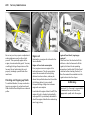
Pict ure no: 14178s.t if
Rear seats
Mov e rear out board seats
Pull ha ndle under sea t, move seat, release
handle and allow seat to engage.
The b ackrests must not be in the rearmost
position when the seats are moved back, in
order to prevent damag e.
Picture no: 14179s.tif
Adjusting b ackr ests of rear
out board seats
Get hold of bac krest, pull handle at
outboard side of seat and guid e b ackrest
into the relevant position. Relea se handle
and allow back rest to engag e.
To extend the luggage compartment, the
seat can be swiv elled down. However, we
recommend always using the seat for
sitting only when in the swiv elled -up
position. To extend the lugga ge
compa rtm ent, see pag e 52.
Seats, Interior
51
Flexible Seat System (FlexSpace)
In the rear row of seats, your vehicle offers
either three seats or two seats with more
seating room, in this case the centre seat
must be folded down. The outboard seat
back rests ca n be swivelled downwards to
increase the size of the luggage
compartment.
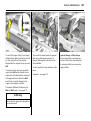
Picture no: 14729s.tif
Tw o rear sea ts with m ore seat ing space
Lower centre seat – see page 53.
Move backrest to centre position, pull
ha ndle beneath seat, slide seat back wards
as fa r as possible, then slide inwards to
centre of v ehicle and further back into the
desired position.
Release handle and allow seat to engage
in position.
Picture no: 14730s.tif
Three seats
Move bac krest to centre position, pull
handle beneath seat, slide seat forwards to
the stop, then slide out towards door and
further forward into the desired position.
Release ha ndle and a llow seat to eng age
in position.
Raise centre seat – see pa ge 53.
52
Seats, Interior
Luggage co mpartment extension
To increase the size of the luggage
compartment, you ca n:
z Fold down the outb oa rd rear seat
backrests,
z Lower the centre seat,
z Swivel down the outboard seats,
z Fold down the front p assenger’s seat
backrest 3 .
See following pag es for instructions.
The rear seats must be in the outboard
positions, see "Three seats" on the previous
page.
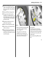
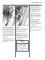
Picture no: 14184s.tif
Fold down outb oa rd rear seat b ackrest
If necessary, remove luggage
compartment cov er 3 – see pag e 54.
Push head restra ints down fully see p ages 4, 45.
Ta ke seat belt out of the belt guide on the
backrest.
Remove the push-in sleeves 3 for m ounting
the IS O-FIX child restraint sy stem – see
separate instructions for the IS O-FIX child
restra int system .
Picture no: 14182s.tif
Hold the back rest, pull handle at outboard
side of seat and fold ba ckrest down onto
seat cushion. Release handle and eng age
bac krest.
9 Warnin g
To prevent injuries, always hold seat
backrest firmly and guide downwards
when folding.
To raise, pull hand le on outboard side of
the seat and raise seat back rest. Release
handle and latch.
Insert seat belt into belt guide on bac krest.
Seats, Interior
53
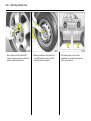
Ra ise outb oard seats
Pull release handle on back of b ackrest
and p ull seat upwards until it engages.
Pull handle on outboard side of rear sea t
and m ove rear seat backrest upright.
Release ha ndle and la tc h into position.
Insert seat belt into belt guide on bac krest.
The seat back rests ca n be righted even
with the seat swivelled bac k. We
recommend only using the seat for sitting
while in the swivelled-up position.
Pict ure no: 14728s.t if
Lower centre seat
House centre seat belt in the holder in the
roof – see page 63.
Insert seat belts into recesses in seat
cushions.
Push centre head restraint as far down as it
will go – see page 45.
Pull release handle at rear of c entre
back rest – see illustration. Tilt back rest
forward and engage.
9 Warning
Loads must not obstruct the operation of
the handbrake and the gears. Pay
attention to notes on pa ge 56.
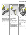
Picture no: 14716s.tif
Raise cent re seat
Pull release handle, m ove ba ckrest up rig ht
and engag e. Outboard seats must be in
the outer position to do this – see rig htha nd colum n on page 51.
Fold ing down out board seats
Push front sea ts forwards or rem ove head
restra ints on the rear outboard seats –
see p age 46.
Fold d own outboard rear seat backrests.
To achieve a level loading surface, pull
relea se handle on ba ck of back rest and
push seat down until it latches into
position.
54
Seats, Interior
Picture no: 14107S.tif
Folding d own the front pa ssenger’s
sea t 3
Push front passenger’s seat hea d restraint
all the way down or remove –
see pages 4, 45, 46.
Push front passenger’s seat backwards.
Raise release lever and fold front
passenger’s sea t forwa rd s.
Rai se front p assenger’s sea t bac krest 3
Raise release lever, lift front passeng er’s
seat a nd audibly engage backrest into
position.
Notes on load ing
See page 56.
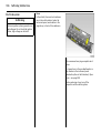
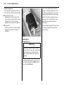
Picture no: 14735S.t if
Luggage compartment cover 3
To op en:
Lift c ov er at rea r and tilt forwa rds, segment
by seg ment.
To close:
Tilt top p art of cover ba ckwards and latch
into position.
Do not p lace any heav y or sharp-edged
ob jects on the cover.
Picture no: 15272s.tif
Remov ing
O pen cov er, d iseng age towa rd s the rear
and remove from above.
Fitti ng
Insert the cover from the rea r, clip into
place and fold back.
Seats, Interior
Pict ure no: 14736s.t if
Safety net
3
The safety net is installed behind the front
seats with the rear seat backrests fold ed
forward.
Passeng ers m ust not be carried behind the
safety net.
Fitting
Fold all rea r seat back rests forwards – see
luggage comp artment extension, p age 52.
The roof frame contains two m ounting
openings: O pen c ov ers.
Hang the upper net rod first in one
aperture and then in the other side; clip in
place by pushing rod forwa rds into smaller
aperture.
Picture no: 17952S.t if
55
Picture no: 16145s.tif
Hook tension straps into lashing eyes 3 or
slots 3 at the rea r of the outer front seat
bracket and tension.
St owage of safety net
Roll up the removed safety net and secure
it with Velcro strips.
On the version without lashing ey es, when
the sa fety net is mounted for the first time,
the slots at the rear of the outer front seat
bracket must first be opened:
Press the marked field at the upper edge
with a blunt object a nd fold inw ards.
S tore the safety net under the floor in the
luggage compa rtm ent. To open, rem ove
the lugg age compartment cov er 3 , see
pag e 54, lift the floor covering by the
handle and raise towards the front, see
pag e 176. Store safety net in front
recesses.
Rem oving
Tilt belt leng th adjuster up wards and
unhook belts. Unhook top net rods and
close two mounting openings.
56
Seats, Interior
Pict ure no: 14718s.t if
Picture no: 14717s.tif
Picture no: 14110s.tif
Lashing eyes 3
Bag hangers 3
Notes on lo ading the vehicle
The lashing ey es in the lugg age
compartment are for securing transported
item s to p revent them from slipping
around .
There a re two retainers on the back of the
outer rear seat backrests for hanging
carrier bag s on. Maximum load : 10 kg per
retainer.
z Heav y objects in the luggage
compartment should be placed as far
forwa rd as possible ag ainst the enga ged
rear sea t backrests or, if the rear sea t
backrests are fold ed d ow n, against the
front seat backrests. If objects are to b e
stack ed, the hea vier objects should be
placed at the bottom. Unsecured objects
in the luggage compa rtm ent would be
thrown forward w ith g reat force in the
event of heavy braking, for exam ple.
Seats, Interior
z Secure heav y objec ts with lashing
straps 3 atta ched to lashing ey es 3 –
see page 56. If heavy loads slip when the
vehicle is braked heavily or driven
around a bend, the handling of the
vehicle may chang e.
z When transporting ob jects with rear seat
backrests tilted forward, fit safety net –
see pa ge 55.
z Close the luggage compartment cover 3
so the rear window does not reflect the
ob jects.
z If the bac krests are not folded down
when transporting objects in the
lugga ge c om partment, they m ust be
engaged in an upright position see pa ge 53.
57
z Do not a llow the load to protrude ab ov e
the upp er edge of the rear seat
back rests, or above the upper ed ge of
the front seat b ackrests if the rear seat
back rests a re folded down.
z Loads must not obstruct the opera tion of
the pedals, the handbrak e or the gears,
or restric t the driver’s freedom of
movement. Do not place loose objects in
the vehicle interior.
z The warning triangle 3 a nd first-aid k it
(cushion) 3 m ust alway s be freely
accessible.
z Do not drive with lugga ge compa rtm ent
open when tra nsporting bulky objects,
for exam ple, since toxic exhaust fumes
could penetra te the interior.
z Do not place any objects in front of the
rea r window or on the instrument pa nel.
They are reflected in the glass, obstruct
the driver’s view and will be thrown
through the vehicle, for insta nce in the
event of heavy b ra king.
z O bjects must not be stored in the airbag
inflation area, beca use they could cause
injury if the a irba g infla tes.
z Weights, payload and roof loa d –
see page 214.
z A roof load increases the sensitivity of
the vehicle to crossw inds and impairs
vehicle handling due to the vehicle’s
hig her centre of gravity. Driving with a
roof load - see pages 138, 141, 163.
9 Warnin g
Failure to observe these descriptions can
lead to injuries which ma y be fatal.
Vehic le pa ssengers m ust be inform ed
accordingly.
58
Seats, Interior
Three-stage safety system
Com prising:
z Three-point seat belts,
z Belt tensioners at the front seats,
z Airbag sy stems for the driver’s seat and
front passenger’ s sea t 3 as well as the
outboard rear seats 3.
The three stages are activated in sequence
depending on the sev erity of the accident:
z The automatic seat belt locking d evices
prevent the belt strap from b eing pulled
out and thus ensure that the vehicle
occ upa nts are retained in their seats.
z The front seat belts are pulled down at
the belt buckles. This mea ns the b elts fit
snugly, the occupants are d ecelerated
early with the vehic le and the stress
placed on the body is reduced .
z The airbag systems are also triggered in
the event of severe a ccidents a nd form a
safety cushion for the occupa nts.
9 Warning
The airb ag systems serve to supplement
the three-point seat b elts and belt
tensioners. The seat b elts must therefore
alway s be w orn. Disreg ard of these
instructions m ay lead to injuries or
end ang er life. Vehicle p assengers must
be inform ed a ccord ingly .
Alw ays read the instructions prov ided w ith
the child restraint system!
Picture no: 13982.tif
Three-point seat belts
The vehicle is equipped with three-point
seat belts with automatic retrac tors and
locking d evices, allowing freedom of body
mov ement although the spring tensioned
belts always ensure a snug fit.
For information on correct seating
position – see pages 44, 62, 68.
The belt has a " vehicle sensitive retra ctor"
which is designed to lock during hea vy
acc eleration or deceleration in any
direction.
Seats, Interior
9 Warning
Alwa ys wea r your seat belt, and that
means a lso in urban traffic a nd when you
are a rear sea t passeng er. I t can save
your life!
Also, pregnant women must alwa ys wear
a seat belt – see pa ge 62.
In the event of an accident, persons not
wearing seat belts endanger their fellow
occupants and themselv es.
Control indicator X for the seat belt –
see page 84.
Seat belts are designed to be used by only
one person at a time. They are not suitable
for anyone under 12 y ears of age or
150 cm .
For children up to 12 yea rs of ag e, w e
recom mend the Vaux hall child restraint
system – see page 65.
Belt force limi ter s
Belt forc e limiters on the front seats reduce
the body load, due to dam ped release of
the belt on a collision. This m eans that the
seat occupants move forwa rd und er
control.
59
Testing the belts
C heck a ll parts of the belt sy stem
period ically for dam age and correct
functioning. R eplace dam aged
components. After an accident, have the
belts and triggered belt tensioners
replaced by a workshop.
Do not perform any altera tions on the
belts, their anchorages, the automatic
retrac tors or the belt buck les.
Mak e sure that b elts are not da maged or
trapped by sharp-edged objec ts.
60
Seats, Interior
9 Warnin g
Eliminate the cause of the fault
immediately by a workshop.
S elf-diagnosis integrated into the system
allows rapid fault identification.
Pict ure no: 14719s.t if
Belt tension ers
The front seat belt systems are eq uipped
with belt tensioners. In the event of a head on or rear-end collision of a c ertain
severity, the belt buc kles are pulled down,
thus tightening the belts.
Actua tion of belt t ensioners
Indicated by illum ination of control
indicator v, see nex t colum n.
If the belt tensioners are triggered, they
must be replaced by a workshop.
Picture no: 17885s.tif
Control i nd icator v for bel t tensioners
The func tion of the belt tensioners and
airbag systems is monitored electronically
and indicated by the control indicator v.
When the ignition is turned on, the control
indica tor illum inates for approx. 4 seconds.
If it does not illum inate, or if it does not go
out after 4 seconds, or if it illuminates while
driving, there is a fault in the belt tensioner
or airbag systems, see pa ge 72. The
sy stems might not trig ger in the ev ent of an
accident.
Deploym ent of the belt tensioners is
indica ted b y continuous illum ination of v.
Seats, Interior
Im portant
z Do not fit ac cessories not spec ifically
released for your vehicle type or store
ob jects in the belt tensioner operating
area (in the area of the belt tensioners)
due to the risk of injury in the event the
belt tensioners are trigg ered.
z Do not m ake any modifications to the
com ponents of the belt tensioners, a s
this will render the vehicle unroadworthy .
9 Warning
Inc orrect handling (e.g. removal or fitting
of seat belts or belt buckles) can trigg er
the belt tensioners; risk of injury.
z The belt tensioner and airbag system
control electronics can be found in the
centre console area . In order to avoid
malfunctions, d o not store magnetic
objec ts in this area.
z When using the rea r seats, ensure that
the front seat b elt comp onents are not
dam aged by shoes or other objects.
Avoid dirt getting into the belt retractors.
61
z We recom mend that you have the front
seats removed by a w orkshop in the
event of actuation of the belt tensioners.
z The belt tensioners trigger once only,
ind ic ated b y the illumination of control
ind ic ator v. Have a work shop replace
trig gered belt tensioners.
z When disposing of the vehicle, the sa fety
instructions given for this must be
observed . Ta ke the vehicle to a recycling
company for disposal.
62
Seats, Interior
Pict ure no: 14120s.t if
Using the belts
Fitting seat bel ts
Pull the belt out of the retractor and guide
it across the body , making certain that it is
not twisted.
Insert the la tch plate into the buckle. The
front sea t b ackrest must not be tilted back
too far or the seat belt will not op erate
properly . The recommended angle of
inclina tion is 25° .
Make sure that the lap belt is not twisted
and that it fits snugly across the body.
Tension the belt freq uently while driving b y
tugging the diagona l part of the b elt.
Picture no: 14121s.tif
9 Warning
O n pregna nt women in particular, the lap
belt must be positioned a s low as
possible across the pelvis so as not to put
too much pressure on the abdomen.
Bulk y clothing prevents the belt from fitting
prop erly. The belt must not rest against
ha rd or fragile objects in the pockets of
your clothing (e.g. ballpoint pens, keys,
spectacles) because these could cause
injury. Do not place any objec ts (e.g.
ha ndb ags, mobile phones) b etween the
belt and your body.
Picture no: 14122s.tif
Height adjustm ent
For height adjustment of the upper guiding
point of the front seat belts:
1. Pull b elt out slig htly.
2. Push button on sliding adjuster.
3. Set desired height.
4. Allow sliding ad juster to a ud ib ly latch.
Do not adjust height while driving .
Seats, Interior
Pict ure no: 13982s.t if
Adjust height such that the belt p asses
over the wearer’s shoulder and rests
against the shoulder. It must not pass over
the neck or upper arm.
Picture no: 14123s.tif
Rem oving t he b el t
To remove the belt, d epress the red
pushbutton on the buckle; the b elt will
retract automatically.
63
Picture no: 14124S.tif
Three- point seat belt on c entr e rear seat
Pull latch p la tes out of belt retainer in roof.
C lic k bottom latch plate into right-hand
buckle (1) on centre seat. Rem ov e top latch
plate from reta iner, guide over shoulder
and la p area with belt (d o not twist) and
click into left buckle (2) on centre seat.
If using the centre seat, both outb oa rd
seats must be pushed back wards and the
bac krests must be flush with the centre
seat backrest, see p age 51.
6
64
Seats, Interior
Mounting brackets 3 for ISO-FIX
child restraint systems
The brackets located between the backrest
and seat cushion are used for mounting
IS O-FIX child restraint sy stems.
Plea se follow the instructions
acc om panying the I SO -FIX child restraint
system.
O nly ISO -FIX child restraint sy stems
app rov ed for the vehicle may be used.
Picture no: 14739S.tif
To remove the b elt, press the button on the
left sid e of the buck le (2). If the central seat
is to be lowered, press the button on the
right side of the buckle (1). The belt retrac ts
automatically.
Push the upper latch p late into the holder
for the lower latch plate. Fold over lock ed
together latch plates ag ainst the belt.
Picture no: 14740S.t if
Insert in the belt retainer in the roof with the
low er latch plate pointing forw ards.
Seats, Interior
Child restraint systems 3
When using a child restraint sy stem, follow
the instructions for installation and use.
The c ountry in which y ou a re travelling
may not perm it the use of child restraint
systems on certain seats. Alw ays comply
with the local or na tional regulations.
Selecting the right system
Your child should travel fa cing backwa rd s
in the v ehicle for a s long a s p ossible.
A child has a v ery weak cerv ic al sp inal
column and in the event of an accident is
less likely to suffer injury in a rearward facing, sem i-lying position than if seated
upright.
9 Warning
Nev er carry child restraint sy stems on
your lap, risk of fatal injury.
Perm issib le options for fitt ing a chil d safety seat1 )
Weight
and
age class 2)
On
front
passeng er ’s seat
On
outboa rd rear seats
On
centre rear seat
0:
up to 10 k g
or approx.
10 months
B1 , +
U, +
U, + +
B2 , +
U, +
U, + +
X
U
U, + +
0+ :
up to 13 k g
or approx.
2 years
I:
9 t o 18 kg
or approx.
8 months to
4 years
II:
15 to 25 kg
or approx.
3 to 7 y ears
III :
22 to 36 kg
or approx.
6 to 12 years
1)
2)
For rea son s of safety, we recomm end tha t the ch ild safety sea t b e insta lled on
on e of the ou ter rea r sea ts .
We recom mend th e u se of each system until the child rea ch es th e u pp er w eig ht limit.
65
66
Seats, Interior
B 1 = Conditiona l, without front
passenger’s airbags or with sea t
occupancy recognition and
Va ux ha ll child restraint systems with
transponders.
The front passeng er’s seat m ust
also have a height adjusting facility:
Move to highest position, slide front
passenger’s seat all the way back
and move front passeng er’s seat
belt anc horage point to lowest
possible position.
B 2 = Conditiona l, without side airbag
with front pa ssenger’s seat slid all
the wa y back , or with seat
occupancy recognition and
Va ux ha ll child restraint systems with
transponders.
The front passeng er’s seat m ust
also have a height adjusting facility:
Move to highest position and slide
front pa ssenger’s seat all the way
back so that the seat belt runs
towards the front from the
anchorag e point.
U = For universal use in com bination
with three-p oint seat belt.
+
= Vehicle seat av ailable with ISO -FIX
fixings. When using ISO -FI X, only
I SO-FIX child restraint systems
a pproved for the vehicle ma y be
used.
++ = O nly if both outboard rear seats are
p ushed back a nd are flush with the
centre sea t.
X = N o child restraint sy stem permitted.
Not e
z Children und er 12 years or und er 150 cm
tall should only trav el in an ap prop ria te
child sa fety sea t.
z When transporting c hildren, use the child
restra int system s suitable for the child’s
weight.
z Check that the child restraint systems
ha ve been correctly installed – see
instructions provided with child restraint
sy stem.
z The covers of the Vauxhall child restraint
sy stem can b e wiped clean.
z Do not stick any thing on the child
restra int systems and do not cover them
with any other m aterials.
z Only allow child ren to enter and exit at
the side fa cing away from the traffic.
z A child restraint sy stem which has been
subjected to stress in an accident must
be replaced.
z Secure or remov e child restraint sy stems
carried in the vehicle when not in use.
Seats, Interior
67
Exception:
Front p assenger’s seat with seat
occupancy recognition sy stem 3.
The seat occupancy recognition system
deactivates the front a nd side airbag s on
the passenger’s sid e if the front
passenger’ s seat is unoccupied, or a
Vauxhall child restraint system with
transponders 3 ha s been fitted to the front
passenger’ s seat.
S eat occupancy recognition – see p age 73.
Vauxhall child restraint system with
transponders 3 – see p age 74.
Pict ure no: 16424s.t if
Picture no: 14317s.tif
Airbag system
z Seat occupancy recognition 3,
Front airb ag
The front airbag system is identified by the
word AI RBAG on the steering wheel and
above the glov e c om partment 3.
z The control indicator for Va ux ha ll child
restraint systems with tra nsponders y 3
in the courtesy light.
The front airbag system comprises:
z An a irb ag with inflator in the steering
wheel and a second behind the trim
panel ab ov e the glove compartment,
z The control elec tronics with impact
sensor,
z Control indicator for airbag sy stems v in
the instrument cluster,
The front airb ag system will be trigg ered :
z Depending on the severity of the
accident,
z Depending on the ty pe of impact,
z Within the range shown in the
illustration,
z Independently of the side airbag
system 3 and curtain airbag sy stem 3.
Examples of events triggering the front
airbag sy stem:
z Impact against a non-y ielding obstacle:
The front airbags are trigg ered at low
vehicle speeds.
z Impact aga inst a y ielding obsta cle (such
as another vehicle):
The front airbags are only trig gered at
hig her vehicle speeds.
68
Seats, Interior
Pict ure no: 14125s.t if
When trigg ered , the front airbags inflate in
milliseconds to form a safety cushion for
the d riv er and front passenger. The
forward movement of the front seat
occupants is c hecked, thereby
sub stantially reducing the risk of injury to
the upp er body and hea d.
No im pairment of view will occur, because
the a irb ags inflate and deflate so quickly .
Picture no: 14100s.tif
Picture no: 13982.tif
9 Warning
The front airbag sy stem provides
optimum p rotection when the seat,
back rest a nd head restraint are correctly
adjusted: Adjust the driver’s seat
according to the occupant’s height suc h
that with the driver sitting upright the
steering wheel is held in the a rea of its
upper sp ok es with the d riv er’s arms
slightly bent.
The front passenger’ s sea t should be as
far bac k as possible, with the backrest
upright (see pages 3, 44). Do not place
your hea d, body , hands or feet on the
covers of the airbag system s.
Do not place any objects in the area in
which the airb ags inflate. Im portant
inform ation – see page 75.
9 Warnin g
The three-point seat belt must b e
correctly fitted – see pag e 62.
The front airbag sy stem will not be
triggered in the ev ent of:
z
z
z
z
The ignition being switched off,
Minor frontal collisions,
Accidents in which the vehicle overturns,
Collisions involving a side or rear-impa ct,
that is to say, if it w ould not be of benefit to
the oc cup ants.
Seats, Interior
9 Warning
Seat belts m ust therefore a lways be worn.
The front a irb ag system serv es to
supplement the three-point seat belts.
If y ou do not w ear your seat belt, y ou risk
being seriously injured, or even thrown
from the vehic le, in the ev ent of an
accident.
In the event of an accident, the belt helps
to keep you in the correct seating
position, so tha t the front airbag system
can provid e you with effective p rotection.
69
In a ddition, the front airbag system will not
be triggered for the front pa ssenger in
model va riants with seat occupa ncy
recognition 3 if:
z The front passenger’ s sea t is
unoccupied,
z There is a properly fitted Vauxhall child
restraint system with transpond ers 3.
Sea t occupancy recognition – see page 73.
Vauxhall c hild restraint system with
tra nsponders 3 – see page 74.
Picture no: 14741s.tif
Si de airba g 3
The side airbag sy stem is identified by the
word AI RBAG on the outboard sides of the
front seat back rests.
The side airbag sy stem comprises:
z An airbag w ith infla tor in the back of the
driver’ s and front passenger’ s seat
respectively,
z The control electronics,
z The side-imp act sensors,
z Control indicator for airbag sy stems v in
instrument cluster,
z Seat occupancy recognition 3 ,
z The control ind ic ator for Vauxhall child
restra int sy stems with transp onders y 3
in the courtesy light.
6
70
Seats, Interior
Exception:
Front passenger’s seat with seat occup ancy
recognition system 3. The seat occupancy
recognition system deactivates the
passenger’ s front and side airbags if the
front passenger’s seat is unoccupied, or a
Vauxhall child restraint system w ith
transponders 3 ha s been fitted to the front
passenger’ s sea t.
Sea t occupancy recognition – see page 73.
Vauxhall c hild restraint system with
tra nsponders 3 – see page 74.
Pict ure no: 14318s.t if
The side airbag system will be triggered:
z Depend ing on the severity of the
accident,
z Depend ing on the type of impac t,
z Within the range shown in the
illustration, from the centre d oor pillar on
the driver’s or front passenger’ s side,
z Ind ependently of the front airbag
system .
Picture no: 14742s.tif
When deployed, the side airbag inflates
within milliseconds to form a safety cushion
for the d riv er or front passenger in the
respective front door area. This
substantially reduces the risk of injury to
the upper b od y and pelvis in the event of a
side-on collision.
Seats, Interior
71
9 Warning
There m ust be no objects in the area in
which the airbag inflates or in the area
between the seat back s a nd the vehicle
body. Do not pla ce the hands or arms on
the covers of the airbag system s.
Important information – see page 75.
The three-point seat belt m ust always be
correctly fitted – see page 62.
The sid e airbags w ill not be trigg ered in the
event of:
z The ignition b eing switched off,
Picture no: 14129s.tif
Picture no: 14318s.tif
The curtain a irba g system w ill be trigg ered :
z Acc idents in which the vehic le overturns,
Curtai n airbag 3
The curtain airbag system is identified b y
the word AI RBAG on the roof pillar trim.
z Collisions inv olv ing a rea r-im pact,
The curtain airbag system comprises:
z Collisions inv olving a side-impact outside
the passenger c ell.
z An airbag w ith inflator in the roof fram e
on the driver’ s and front passenger’s side
respectively ,
z Depending on the type of impa ct,
z Frontal collisions,
In add ition, the side airbag system will not
be triggered for the front passenger in
model variants with seat occupancy
recognition 3 if:
z The front p assenger’s seat is
unoccupied ,
z There is a p roperly fitted Va ux ha ll child
restraint system with transponders 3 .
Seat oc cup anc y recognition – see pag e 73.
Vauxhall child restraint sy stem with
transponders 3 – see pa ge 74.
z The control electronics,
z The side-impact sensors,
z C ontrol indicator for airbag systems v in
the instrum ent cluster.
z Depending on the severity of the
accident,
z Within the range shown in the
illustration, from the centre door pillar on
the driver’s or front pa ssenger’s side,
z Tog ether w ith the sid e airbag sy stem,
z Irrespectiv e of seat oc cup anc y
recognition,
z Independently of the front a irba g
sy stem.
6
72
Seats, Interior
9 Warning
There must be no objects in the area in
which the airb ag inflates or in the a rea
between the seat backrests and the
vehicle body .
Do not place the hands or arms on the
covers of the airbag system s.
Imp ortant information – see page 75.
The three-point sea t b elt must a lw ays be
correctly fitted – see page 62.
Pict ure no: 14127s.t if
When the curtain airbag is trig gered, it
infla tes within millisecond s a nd provides a
safety barrier in the head a rea on the
respective side of the vehicle. This reduces
the risk of injury to the head c onsiderab ly in
case of a sid e-impac t.
The curta in airba gs will not be triggered in
the event of:
z The ig nition being switched off,
z Frontal c ollisions,
z Accidents in which the vehicle ov erturns,
z C ollisions involving a rear-impac t,
z C ollisions involving a side-imp act outside
the passenger cell.
Picture no: 17885s.tif
C ont rol indic ator v for ai rbag syst em s
The function of the airbag sy stems is
monitored elec tronically together with the
seat occupancy recognition 3 a nd the b elt
tensioners, and indicated by the control
indicator v.
When the ignition is switched on, the
control ind icator illum inates for a pprox.
4 seconds. If it d oes not illuminate, does
not go out after 4 seconds or illuminates
while driving, there is a fault in the a irb ag
systems, seat occupancy recognition 3 or
in belt tensioners. See also page 60. The
systems ma y fail to trigger in the event of
an ac cident.
Deployed airbags are ind icated by
continuous illum ination of v.
Seats, Interior
9 Warning
9 Warnin g
Have the cause of the fault eliminated
im med ia tely by a work shop.
Only Vaux hall child restraint systems with
tra nsponders 3 can be fitted on the front
passeng er’s seat. Use of sy stems w ithout
tra nsponders poses a risk of fatal injury.
Self-diagnosis integrated into the system
allows rapid fault identification.
Seat oc cupancy recognition 3
The seat occupancy recognition system
deactivates the front and side front
passenger’s airba gs if the front
passenger’s sea t is unoccupied or a
Vauxhall child restraint sy stem with
transponders 3 has been fitted to the front
passenger’s sea t. The curtain airbag
system 3 rem ains activ ated.
The c ontrol indicator for seat occupancy
recognition y is located in the front
courtesy light. I f control indicator y
illuminates for approx. 4 seconds after the
ignition is switched on, the vehicle is
equipp ed with seat occupancy rec ognition
– see pa ge 74, Fig. 12135 S.
If a Vauxhall c hild restra int system
with transponders 3 is fitted, c ontrol
indicator y illuminates perm anently after
the ig nition is switched on, as soon as the
system has detected the child restraint
system. Only then may the child restraint
system with transponders 3 be used on the
front passenger’s seat.
73
Vauxhall child restraint systems with
transponders 3 can b e identified by a
sticker or badge.
Pict ure no: 15844t.tif
Vehicles with seat occupancy recognition
can b e identified by the sticker on the front
passenger’s seat or on the side of the
instrument panel.
Vauxhall c hild restraint system s w ith
tra nsponders 3 are automatically
detected if correctly fitted to the front
passenger’s seat. When these child
restra int system s a re being used on the
front passenger’ s seat, the front and side
airbag systems for the front passenger’s
seat are dea ctiv ated. The curtain airbag
sy stem rem ains ac tiv ated.
Pa y attention to the control indicator y
for seat occupancy recognition 3 –
see p age 74.
74
Seats, Interior
Cont rol indica tor y for Vauxha ll child
restraint syst em s with t ransponders 3
The p resence of a Vaux hall child restraint
system with transp onders is ind ic ated after
the ig nition has been switc hed on, b y
permanent illumination of the control
indicator y in the front courtesy light, a s
soon a s the seat occupancy recognition
system has detected the child restraint
system.
If c ontrol indicator y flashes when the
child restraint system with transponders is
correc tly fitted, there is a fa ult, with risk of
fatal injury to the child. In this case, only fit
child restraint systems to the outer rear
seats. H ave the cause of the fault
elimina ted b y a work shop.
If no Vauxhall child restraint system
with transponders is fitted, the control
indicator must not illum inate or flash,
as the front passenger’ s a irb ag systems
would not deploy in the ev ent of a collision.
Hav e the cause of the fault elim ina ted by a
workshop.
Picture no: 12097s.tif
If control indicator y does not illum inate
while driving, the front and side airbag s for
the front passenger’s seat have not been
deactiv ated a nd there is a risk of fa ta l
injury to the child. In this ca se, only fit child
restra int system s to the outer rea r seats.
Have the cause of the fault eliminated by a
work shop.
If the child restraint system is not correc tly
installed or the transponders a re defective,
the control indic ator will fla sh. C heck for
correct child restraint system installation.
For insta lla tion of child restraint system
with tra nsponders 3 – see instructions
prov ided with child restraint sy stem.
Seats, Interior
9 Warning
If a Vauxhall child restraint sy stem with
transponders has been fitted a ccord ing
to the instructions, the control indica tor
for Vauxhall child restraint systems with
transponders y must illumina te in the
front courtesy light when the ignition is
switched on.
If the control indicator does not illuminate
while driving, the front passenger’s
airb ag systems have not been
deactiva ted a nd there is a risk of fatal
injury. In this case, fit child restraint
system s to the outer rear seats only. Hav e
the cause of the fault eliminated by a
work shop.
Imp or tant
z Due to risk of injury when the airbag s
deploy, a ccessories and objects should
not be placed within the expansion
range of the airbag sy stems.
z Do not place any objects between the
airbag sy stems and the v ehicle
occupants; risk of injury.
9 Warning
Never carry child restraint systems or
other objects on y our la p - risk of fatal
injury .
z Use the hook s in the roof fram e only to
hang up light articles of clothing or coat
hangers. Do not p la ce any objects in the
pockets of the hanging item s – risk of
injury .
z The airb ag systems and b elt tensioner
control electronics can be found in the
centre console area . In order to avoid
malfunctions, d o not store magnetic
objec ts in this area.
75
z Do not stick any thing on the steering
wheel, instrument panel, front seat
backrests or roof frame, in the vicinity of
the airbags, or on the front p assenger’s
seat cushion, or cover any of those areas
with other materia ls.
z Use only a dry cloth or interior c leaner to
clean the steering wheel, instrument
panel, front seat backrests, roof fra me
and seat cushion of the front
passeng er’s seat. Do not use any
aggressive cleaning agents.
z Only protective covers which are
approved for your vehicle with side
airbag m ay be fitted on the front seats.
When fitting the protective cov ers, make
sure tha t the airbag units on the
outboard sides of the front seat
backrests are not covered.
z The airbag sy stems are triggered
ind epend ently of each other depending
on the severity of the accident a nd the
type of imp act. The side airbag sy stem 3
and the c urtain airbag sy stem 3 are
trig gered together. See seat occupancy
recognition 3 on pag e 73 for ex ceptions.
z Each a irb ag deploys once only. Have a
workshop replace dep loy ed airbags
immediately.
76
Seats, Interior
z The speeds, directions of movement and
deformation properties of the vehicles,
and the properties of the obstacle
concerned, d eterm ine the severity of the
accident and trig gering of the airb ags.
The degree of damag e to y our v ehicle
and the resulting repa ir costs alone a re
not indicative that the criteria for
trigg ering of the airba gs were met.
z When disposing of the vehicle, the safety
instructions g iven for this must b e
observed. Take the v ehicle to a recy cling
compa ny for disp osal.
z Do not p erform any a lterations on the
com ponents of the airbag sy stem, as this
would render the vehic le unroadworthy .
z In v ehicles with seat occ upa ncy
rec og nition 3, do not place any heavy
objec ts on the front passenger’ s seat
otherwise the airbag system s for the
front p assenger’s seat may b e triggered
in the event of an accident.
9 Warning
The systems can be triggered ab ruptly
and cause injury if they are handled
im properly.
z We recom mend hav ing the steering
wheel, the instrument p anel, all panelling
parts, the door seals, the hand les and
the seats rem ov ed by a workshop.
z Persons weighing less than 35 kg should
only travel on the rear seats. This does
not apply to children who are travelling
in child restraint systems with
transp onders 3.
z In v ehicles with seat occ upa ncy
rec og nition 3, to prev ent malfunctions
do not use protective c ov ers or extra seat
cushions on the front passeng er’s seat.
z When using a Vauxhall c hild restraint
sy stem with transponders 3 on the front
passeng er’s seat, in order to prevent
malfunctions, no objects (e. g. pla stic
sheet, stickers or heated mats) may be
placed und er the child restraint sy stem.
9 Warnin g
Child restraint systems as well as other
objects must never be carried on the lap
of passengers; risk of fatal injury . If
carried in this way , child restraint system s
with transponders 3 in vehicles with seat
occupancy recognition 3 could lead to
front passenger’ s airb ag systems not
being triggered in the event of an
accident.
Seats, Interior
77
Use of child restrai nt systems 3 on the
front p assenger’s sea t in vehicl es wi th
airb ag system s 3 , but w ithout seat
occupa ncy recog ni tion 3
9 Warning
Vehicles with front passenger’ s airbag
without side airb ag 3: Child restraint
system s fac ing the rear of the vehicle
must not be installed on the front
passenger’s seat, risk of fatal injury.
Child restraint sy stems facing the
direction of travel (child restra int systems
for weight classes I, II a nd III , see p age 65)
may be insta lled on the front passenger’s
seat if the seat has been pushed ba ck as
far as it will g o and the backrest has been
adjusted suc h that the lap belt fits snug ly.
Picture no: 11704a.tif
Vehicles with front passeng er’s airbag can
be recognised by the word AI RBAG above
the glove compartment and by the sticker
on the instrum ent p anel on the passenger’s
side - see illustration above.
Picture no: 14791s.tif
9 Warnin g
Vehic les with sid e airbag 3:
No child restraint system 3 may be
fitted on the front passenger’ s sea t;
risk of fatal injury.
A v ehicle with side airbags can b e
identified by the word A IRBAG on the
outboard sides of the front seat b ackrests.
S eat occupancy recognition 3 –
see page 73.
78
Seats, Interior
The seat occupancy recognition system
detects Vauxhall child restraint sy stems
with transponders 3 and switches off the
front and side airbag system s for the front
passenger’ s seat. The curtain airba g
system remains activated.
S eat occupancy recognition – see page 73.
Vauxhall child restraint systems with
transponders 3 can b e identified by a
sticker or badge.
Pi cture no: 15844t.tif
Use of child restrai nt systems 3 on front
passenger’s seat in vehicles wit h airbag
systems 3 a nd wit h seat occupancy
recogniti on 3
9 Warning
Only Vauxhall child restraint systems with
transponders 3 can be fitted on the front
passenger’s seats. Use of system s
without transponders poses a risk of fatal
injury.
Vehicles with seat oc cup anc y recog nition
are identified by a sticker on the lower
panel of the front passeng er’s seat –
see illustration above.
Picture no: 12097s.tif
Vehicles with seat occupancy recognition
can also be recognised by control
indica tor y in the front courtesy light.
If control indicator y illuminates for
approx. 4 seconds after the ignition is
switched on, the vehicle is equipped with
seat occupancy rec ognition - see page 73.
Seats, Interior
79
The maximum power c onsumption of
electrical ac cessories m ust not ex ceed
120 w atts.
Do not connect any current-delivering
acc essories, e.g. electrical charging
devices or b atteries.
Electrical ac cessories connected to the
socket must c om ply with the
electromagnetic compatibility
requirements laid down in DIN VDE 40 839,
otherwise v ehicle malfunctions may oc cur.
Pict ure no: 14111s.t if
Picture no: 16111s.tif
Cigarette lighter 3
Accessory soc kets 3
The c ig arette lighter is behind the ashtray
cover.
An accessory sock et is located behind the
ashtray cover. Additional accessory
sockets 3 can b e found in the centre
console in front of the back rests and in the
lugg age compartment.
The c ov er opens w hen pressed a t the
centre point. See Fig. 14354 S on page 80.
Press in cigarette lighter with the ignition
switched on. S witches off autom atically
when elem ent is glowing. Withdraw
cigarette lighter.
Ac cessory sockets can be used to connect
electrica l accessories.
Ac cessory sockets are operable when the
ignition is switc hed on. Use of the sockets
while the engine is not running w ill drain
the battery.
Do not d amage the socket by using
unsuita ble plugs.
If the tyre repair k it is 3 is in operation, no
consum ers may be connected to the
auxiliary sock et.
80
Seats, Interior
Pict ure no: 14111s.t if
Ashtrays
To be used only for ash and not for
combustible rubbish.
9 Warning
Failure to observe these descriptions can
lead to injuries which may be fatal.
Vehicle passengers must be informed
according ly .
Ashtray, front
The cover opens when pressed at the point
indicated .
Picture no: 16110s.tif
To empty , grip b oth sides of the ashtray
insert a t the points illustrated and pull
up wards.
Picture no: 14114s.tif
Rear a sht ray 3
In the rear c entre console.
To open, pull ashtray towards the rear of
the vehicle.
To empty, open the ashtray, press the
spring (see arrow in illustration) and pull
out the a shtray.
Seats, Interior
Pict ure no: 17884s.t if
Ashtray 3
For universal use in vehic le interiors, e.g . in
the front or rear of the centre console or in
foldaway tables 3 (see next page).
O pen cover to use.
Picture no: 11699s.tif
Stowage compartments
Stowa ge compa rtment beneath front
passenger’s seat 3
Lift tray by grasping recessed edge and
pull forwards. Maximum load : 1 kg.
To close the tray , push it in and lock it in
place.
81
Picture no: 14115s.tif
Glov e c ompar tment
To open, pull handle upw ards.
O n the insid e of the glove compartment
cover there is a pen holder.
The glove com partment should be closed
while driving.
C ooled glove compartm ent 3 –
see page 119.
82
Seats, Interior
Foldaway tables
3
Located on the front seat back rests.
O pen b y pulling upwards until it engages.
Fold away by pressing d ow n past the
resistance p oint.
Do not place any heavy objects on the
foldaway tables.
Pict ure no: 11701s.t if
Stow age com partm ent for glasses 3
Loc ated on d riv er’s side. Fold down to
open.
Do not store heav y objects in the stowag e
compartment.
Picture no: 16384s.tif
Stowa ge c ompart ments in rea r footwell 3
To open, unclip cover at recess and lift up.
Seats, Interior
Sunvisors
Use the sunvisor to p rotect from glare, by
pulling it down and/or swivelling it to the
side.
While driving, the mirrors in the sunvisors
should be covered.
Pict ure no: 14116s.t if
Coin holder
Loc ated in the centre console.
83
84
In struments, Controls
Instruments,
Controls
Picture no: 17876s.tif
Control indic ators
Control indicators .... ..... .... ..... .... .... ..... .
Instrument display ... ..... .... ..... .... .... ..... .
Information display . ..... .... ..... .... .... ..... .
Warning buzzers.. .... ..... .... ..... .... .... ..... .
Wind screen wiper .... ..... .... ..... .... .... ..... .
Wind screen wash system and
headlight wash system 3 ... .... .... ..... .
Rear window wash and wiper system
84
89
92
103
103
104
104
The control indica tors described here are
not present in all vehic les. The descriptions
however, apply to all instrument versions.
The control indica tor colours mean:
z Red
z Y ellow
Danger, important rem ind er,
Warning , note, fault,
z Green
z Blue
O n confirmation,
O n confirmation.
X
Picture no:
Seat belt wa rning devic e 3
C ontrol indicator illuminates in red.
Illuminates after turning on the ignition
(with warning tone) until the seat belt is
app lied. Ap ply seat belt, see pa ge 62.
B
Ad aptiv e Forwa rd Lighting (AFL) 3
C ontrol indicator illuminates in yellow .
If it is illuminated:
Fault in sy stem.
C ontact a workshop for help.
AFL 3 – see pag e 109.
In struments, Controls
85
Z
Exhaust emi ssion
C ontrol indicator illuminates or flashes in
yellow.
It illuminates w hen the ignition is switched
on and g oes out shortly after the engine
starts.
If it illuminates w hen the engine is running:
Fault in emission c ontrol system. The
permitted emissions may be ex ceeded.
C ontact a workshop immediately.
>
Pict ure no: 18385s.t if
Front fog lig hts 3
Control indicator illum inates in green.
It is illuminated when the front fog lights
are on – see page 106.
A
Eng ine electr oni cs,
tra nsm ission electronic s, immob iliser,
diesel fuel filter 3, Easyt ronic 3, fault
Control indicator illum inates or flashes in
yellow.
It illuminates for a few seconds when the
ignition is switched on.
Picture no:
Illum inates when the engine is running:
Fault in eng ine or gearbox electronic
sy stem. Electronics hav e switched to
emergency running programm e. Fuel
consumption may be increased a nd the
vehicle’s driveab ility reduced, see
page 147. C ontact a workshop
immed iately.
For vehicles w ith a diesel engine, the diesel
fuel filter m ay need to be drained of water,
see p age 230.
If it flashes when the ignition is on:
Fault in the electronic im mobiliser sy stem;
the engine cannot be started –
see p age 27.
If it flashes when the engine is running:
Fault which could lead to damag e to the
cataly tic conv erter, see pa ge 147. Contact
a work shop imm ediately.
v
Airb ag system s 3 ,
b elt tensioners
C ontrol indicator illuminates in red.
If it illuminates w hen the engine is running:
Fault in the airbag or belt tensioner
systems, see pa ges 60, 72.
86
In struments, Controls
O
Turn signal lights
C ontrol indicator flashes green.
The corresp onding c ontrol indicator
flashes on the side selected.
Both control indic ators flash with the
hazard warning lights on.
Rapid flashing:
Failure of a turn signal bulb or
associa ted fuse.
C ha nge bulbs, see page 190.
Fuses, see page 188.
I
Pict ure no: 17876s.t if
Eng ine oi l pressure
Control indicator illum inates in red.
It illuminates when the ignition is switched
on and goes out shortly after the engine
starts.
If it illuminates when the eng ine is running:
Engine lubrication ma y b e interrupted. This
may result in d amage to the engine a nd /or
locking of the drive wheels:
1. Move out of the flow of tra ffic as quickly
as possible, without imp eding other
vehicles.
2. Depress clutch.
Picture no:
3. Mov e gearshift lever to neutra l, or with
Easy tronic 3 , place selector lever in N.
4. Sw itch off ignition.
9 Warning
When the engine is off, consid erably
more force is need ed to brak e and steer.
Do not rem ov e key until vehicle has come
to a standstill, otherwise the steering
column loc k could eng age unex pectedly.
Check oil level before contacting a
work shop.
C
Headl ight m ain beam
C ontrol indicator illuminates in blue.
It is illuminated when main bea m is on and
during head lig ht flash – see p ages 9, 105.
In struments, Controls
87
If it illuminates w hen the engine is running:
S top, sw itc h off engine. Ba ttery is not
charging. Check drive belt c ondition and
tensioning before contacting a workshop.
R
Brak e system,
cl ut ch system 3
C ontrol indicator illuminates or flashes in
red.
It illuminates after the ignition is turned on,
when the handbrake is applied or if the
brak e or clutch fluid lev el is too low. For
further inform ation, see p ages 156, 232.
j
Pict ure no: 18385s.t if
Easytronic 3, start engi ne
Control indicator illum inates in yellow.
It illum ina tes if the footb ra ke is not applied
when starting the engine. The indicator
goes off as soon a s the footbra ke is
applied. The engine can only be sta rted
with the footbrake applied, see pag e 133.
Picture no:
9 Warnin g
m
Cruise control 3
Control indica tor illuminates in green.
It is illum inated when the sy stem is on – see
page 151.
Illum ina tes when the ha nd brake is
applied . Stop driv ing immediately .
Contact a w ork shop imm ediately.
Fog t ail li ght
Control indica tor illuminates in y ellow.
O n vehicles with Easytronic 3, control
indicator R flashes for a few second s after
the ignition is switched off, if the
handbrake has not been applied.
Easytronic winter prog ramm e 3
Control indicator is illuminated when winter
programme is enab led.
It is illuminated when the fog ta il light is on
– see page 107.
u
Further information – see pa ge 135.
Alternator
Control indica tor illuminates in red.
T
r
p
It illum ina tes when the ignition is switched
on a nd goes out shortly after the engine
starts.
Anti -lock Bra ke Syst em (ABS )
C ontrol indicator illuminates in red.
If it illuminates w hile driving:
Fault in ABS, see pa ge 156.
88
In struments, Controls
If it flashes:
Fuel supply exhausted, refuel immediately .
N ever let the tank run dry!
Erra tic fuel sup ply can c ause catalytic
converter to overheat, see pa ge 145.
Diesel engines:
If the tank is run dry, bleed the fuel system
as desc ribed on pa ge 170.
!
Prehea ting system for diesel engines 3,
d i esel par ticle filt er 3
C ontrol indicator illuminates in yellow .
S
Pict ure no: 17876s.t if
Eng ine oi l level 3
Control indicator illum inates in yellow.
In vehicles with engine oil lev el check, the
oil lev el is chec ked autom atically .
If it illum ina tes when the engine is running:
Engine oil level too low. C heck engine oil
lev el and top up engine oil if necessary, see
page 228.
EPS1 )
Elec tric Power St eering
Control indicator illum inates in yellow.
Fault in Electric Power S teering. Vehicle can
still b e driven, but greater forc e is required
for steering. Contact a workshop
immediately .
1)
EPS = Electric P ower Steering .
v
Picture no:
Electronic Stab ility Program me
(ESP® Pl us ) 3
Control indica tor flashes or illuminates in
yellow.
If it flashes during d riv ing:
System actively enga ged, see page 149.
If it illum ina tes while driv ing:
Fault in Electronic Stability Program me,
see p age 149.
Y
Fuel level
Control indica tor illuminates or flashes in
yellow.
If it illum ina tes:
Low fuel level, fuel gauge in reserve area.
Preheating system active, switches on only
if outside temperature is low.
If it flashes (with diesel particle filter):
Diesel particle filter must be cleaned .
C ontinue driving, and as soon as road and
traffic conditions allow, increase speed to
over 25 m ph (40 km/h) to start c leaning of
the diesel p artic le filter. The control
indicator goes out when cleaning is
complete. We recommend not turning off
the ignition during cleaning.
Further information – see page 148.
In struments, Controls
y
Pict ure no: 12097s.t if
Seat oc cupancy recognition 3
see pages 67, 73.
Picture no: 17879s.tif
In strument display
In some versions, the pointers of the
tachom eter, the speedometer, the c oolant
temperature gauge and the fuel gauge
briefly go to the end stop as a functionality
check.
89
Picture no:
Mil ea ge / k ilometre di sp lay
If the ignition is off, the mileage is
displayed for approx. 15 seconds b y briefly
pressing the reset knob.
Top line:
Trip odometer
Ta chometer
Indicates eng ine speed.
Display of m iles / kilom etres cov ered since
last reset.
Warning zone: Max im um permissible
engine speed exceed ed; danger to engine.
To reset, hold the reset knob d epressed
for a few seconds when the ignition is
switched on.
Speedometer
Speed d isplay .
Bottom line:
O dometer
Records the miles / kilometres driven.
Maintenance, Inspec tion system see pages 91, 226.
90
In struments, Controls
For physical reasons, the engine
temperature gauge show s the coolant
temperature only if the coolant level is
adeq uate.
During operation, the system is
pressurised. The tem perature may
therefore rise briefly to ov er 100 ° C.
Pict ure no: 17906s.t if
Coola nt temperat ure d isplay
Pointer in zone at = Engine operating
left
temperature not y et
reached.
Pointer between
the z ones
= Normal operating
temperature.
Pointer in zone a t
right
(warning zone)
= Temperature too
high:
Stop vehicle and
switch off eng ine.
Danger to engine.
Check coolant level,
see p age 231.
Picture no: 17907s.tif
Fuel gauge
Pointer in red
warning
zone or Y
illuminated
Pointer in red
warning
zone or Y
flashing
= Reserv e level.
= Refuel immediately –
see page 143.
N ever run the tank dry !
Diesel engines: I f the tank is run dry, b leed
the fuel sy stem as desc rib ed on pag e 170.
Because of the fuel remaining in the tank,
the amount of fuel required to fill the tank
ma y be less than the spec ified tank
cap acity.
In struments, Controls
R
Reverse gea r.
N
A
N eutral.
Automatic mode of Easy tronic.
1-5
Manual m od e, current gear of
Easy tronic.
Easy tronic 3 - see page 132.
Pict ure no: 17901s.t if
Servi ce display 3
When the indica tor in the display of the
odometer app ears, mak e a Service
appointment with a workshop as soon as
possible.
Maintenance, Inspection system see page 226.
Picture no: 17878s.tif
Tr ansm issi on display 3
Display of current gear or mode with
Easytronic 3.
91
92
In struments, Controls
For Infotainment system, see Infotainment
system op erating instructions.
Ü Board Computer
BC 1
12:01 17,0°C
FM 3 90,6 MHz
REG
AS
RDS
All values
BC 2
Timer
1
257.0
Ø 40
8
7.0
Ø 31.0
TP
Pict ure no: 17913s.t if
Information display
Tripl e I nformati on Di sp lay 3
Display of time, outside tempera ture and
date / Infotainment sy stem (when it is on).
When the ignition is off, the time, date and
outside tem perature can be made to
appear for approx. 15 seconds by briefly
pressing one of the two buttons adjacent
to the d isplay .
An F in the display indica tes a fault.
Hav e the cause eliminated by a workshop.
19,5° 19:36
miles
mph
gals
mpg
Pict ure no: 16719t.tif
Graphica l Informa tion Display 3,
Colour Inform ation Displ ay 3
Display of time, outside temp erature a nd
date / Infotainment system (when it is on).
The Graphical Information Displa y
presents the information in monochrome.
The Colour Information Display presents
the inform ation in c olour.
The information that is d isplay ed depend s
on the Infota inm ent system c onfiguration.
Some information app ears in the disp lay in
an abbreviated form.
An F in the display ind icates a fault.
Hav e the ca use eliminated b y a workshop .
In struments, Controls
93
9 Warnin g
8:56
-5 ,5° C
07.04.2004
Caution: The road surface may already
be icy , ev en though the display ind ic ates
a few deg rees ab ov e 0 °C .
:
Slippery road
-2, 5°C
OK
Pict ure no: 17913s.t if
Outside temperature
A fall in temperature is indica ted
immediately and a rise in temp erature
after a time delay .
If the externa l temperature falls to 3 °C, to
warn of ice on the road the symbol :
appears in the Triple Informa tion Display.
When the temperature climbs, the
symbol : goes out above 5 °C.
Pict ure no: 16707t.tif
In vehicles with Graphic al Inform ation
Display 3 or Colour Information Display 3,
an icy road surface warning message
appea rs in the disp la y.
No message is disp la yed if the
temperature is less than -5 °C.
94
In struments, Controls
8 :56
5 ,5°C
07.04.2004
Pict ure no: 17914s.t if
Triple Information Display
Set d ate and ti me
With Infotainment sy stem off,
press Ö and ; next to the display as
follow s:
Press Ö for ap prox . 2 seconds:
Day fla shes
;: Set day
Ö : Month fla shes
;: Set month
Ö : Year flashes
;: Set year
Ö : Hours flash
;: Set hours
Ö : Minutes flash
;: Set minutes
Ö : Clock is started.
Correcting time:
Some RDS transmitters do not send a
correct time sig nal. If the incorrect time is
display ed on frequent occasions,
deactiv ate autom atic time synchronisation
– see nex t colum n, and set the time
manually.
Deactivating / activating automatic tim e
synchronisation: With Infota inm ent sy stem
off, press Ö and ; next to the display:
The automatic setting is indicated by } in
the display.
Press Ö and hold down for approx.
3 seconds until } flashes in display 3
and text " RDS TIME" ap pears (years
flash during this time),
Hold down Ö for a pprox. 2 sec., cloc k
display is now in setting m ode,
Press Ö twice (until year flashes).
Press ;; display shows:
RDS TIME 0 = O ff
Press ;; display shows:
RDS TIME 1 = O n
Press Ö three tim es.
In struments, Controls
FM AS
[TP]
�
REG
C Din
95
MP3
90.6 MHz
19,5°
19: 36
Pi cture no: 16711t.tif
Graphical Info rmatio n D isplay 3
or Colour Information Display 3 ,
selecting functio ns
Functions and their menus are shown in the
Graphical Information Displa y and C olour
Information Display .
These functions are highlighted or
executed in the m enu display v ia the
four-wa y b utton, the m ulti-func tion knob 3
on the I nfotainment S ystem or the rem ote
control buttons 3 on the steering wheel.
Pict ure no: 15593t.tif
To select w ith four-wa y but ton
Select menu items via menus and with the
buttons / four-way button of the
Infotainment sy stem.
Picture no: 15559t.tif
Selecti on with the mul ti-function k nob 3
Turn:
Highlighting of menu options or
comm ands, selection of func tion ranges.
Press:
S elec tion of highlighting, confirma tion of
comm ands.
To exit a m enu, turn the m ulti-func tion
knob left or right to Return or Mai n and
select.
6
96
In struments, Controls
7
FM AS
[TP]
REG
C Din
MP3
Settings
Time, Date
19,5° 19:36
19:36
Language
�
90.6 MHz
Units
10 . 07 . 2004
Contrast
Day / Night
19,5°
Pict ure no: 14034s.t if
Selection using rem ot e c ontrol butt ons 3
on steeri ng wheel
Select menu options v ia menus and w ith
the b uttons.
19: 36
Pict ure no: 16711t.tif
For each functional area, there is a m ain
page (Main), which is selected at the top
edge of the d isplay (not with the
Infotainment sy stem CD 30 without the
ha nds-free mobile phone system):
z
z
z
z
Audio,
Na vigation 3,
Telephone 3 ,
Trip comp uter 3.
Function areas audio, nav ig ation 3 and
telep hone 3 – see Infotainment sy stem
op erating instructions.
6 Ign. logic
Picture no: 16712t.tif
System settings
The settings are accessed via the Setting s
menu.
Press the Ma in button 3 (not found on all
Infotainment sy stems) on the Infotainm ent
system (c all up main display).
Press the S ett ings button on the
Infotainment system. For I nfotainment
system CD 30, no menu m ay b e selected.
The Settings m enu is displa yed.
In struments, Controls
7
Time, Date
Time
Date
19,5° 19:36
19:36
10 . 07 . 2004
6 Synchron. clock automatical.
Correcting time:
Some RDS transmitters 1) do not send
correct time sig nals. If the incorrect time is
frequently d isplay ed, deac tiv ate
autom atic time synchronisation and set the
tim e m anually .
To correct tim e with the help of RDS, select
menu item Synchron. clock autom atica l.
from the Time, Da te menu.
The box in front of Synchron. clock
automat ical. will be ticked – see
Fig. 16713 T.
Pi cture no: 16713t.tif
7
Settings
97
19,5° 19:36
Time, Date
Language
Deutsch
Units
English
Contrast
Español
Day / Night
...
6 Ign. logic
Picture no: 16714t.tif
Setti ng the date and time 3
Select menu item Time, Dat e from the
Setti ng s menu.
Languag e selection
Y ou can select the display language for
some functions.
The m enu for Time, Date is displayed.
Select the menu items required.
S elec t menu item Language from the
Sett ings menu.
Make the desired setting.
The available languages are displayed.
6
1)
RDS = Rad io D ata S ys tem.
98
In struments, Controls
7
13 Languages
19,5° 19:36
X Deutsch
7
Settings
Language
Español
Units
Nederlands
Contrast
F rançais
Day / Night
Italiano
6 Ign. logic
Pi cture no: 16715t.tif
Selections are indicated by a 6 in front of
the m enu item .
In systems with voice output 3, w hen the
language setting of the d isplay is changed,
the system will ask whether the
announcement language should also be
changed – see Infotainment system
opera ting instruc tions.
7
Contrast
19,5° 19:36
Time, Date
English
Select the desired language.
19,5° 19:36
~
|
|
|
Europe-SI
Japan
12
Great Britain
USA
Pict ure no: 16716t.tif
Setting unit s of m easur e
You can select which units of measure are
to be used .
Select menu item U ni ts from the S et tings
menu.
The ava ilab le units are display ed.
Select the desired unit.
Selections are indicated by a o in front of
the menu item.
Picture no: 16717t.tif
Ad just ing contra st 3
(Graphic al Inform ation Displ ay)
S elec t menu item Cont rast from the
Sett ings menu.
The menu for Contr ast is disp layed .
C onfirm the required setting .
In struments, Controls
Setti ng displa y ill um inati on 3
The d isplay can be adjusted to suit the
lighting conditions, black or coloured text
on a lig ht bac kground or white or coloured
tex t on a dark backg round.
Select menu item Day / N ight from the
Setti ng s menu.
The options are display ed.
Autom atic:
Adapted based on vehicle lighting .
Alw ays da y design:
Black or coloured text on light bac kground.
Alw ays night desi gn:
White or coloured text on dark
back ground.
Selections are indicated by a o in front of
the m enu item .
Ig ni tion logic 3
See Infotainment sy stem opera ting
instructions.
Ü Board Computer
BC 1
19,5° 19:36
All values
BC 2
Timer
99
1
257.0
Ø 40
8
7.0
Ø 31.0
Range
miles
mph
Inst. Consumpt.
Aver. Consump.
257 miles
31 mpg
31 mpg
gals
mpg
Pict ure no: 16719t.tif
Graphic al Information Display 3
or Colour Information Display 3,
trip computer 3
The trip computers provide information on
driving data, which is continually recorded
and ev alua ted electronically.
The on-board computer main page gives
information on range, instantaneous
consumption and average consumption 3.
To display the other trip computer d riv ing
information, press BC button on
Infotainment sy stem 3 or select trip
computer menu on disp la y.
For vehicles with Infotainm ent
System CD 30 3 and steering wheel rem ote
control 3 , the left-hand steering wheel
buttons only opera te the trip computer.
19,5°
19: 36
Picture no: 16710t.tif
Ra ng e
Range is calculated from current fuel tank
content and instantaneous consumption.
The display shows av erage values.
When the vehicle has been refuelled, the
range is up dated autom atically after a
brief delay .
100
In struments, Controls
Di st ance trav ell ed
Display of miles / kilometres travelled.
The measurement ca n be reset to zero at
any time and restarted, see nex t colum n.
Range
2 3 m ile s
Ü
Average speed
Calculation of avera ge speed.
The measurement ca n be reset to zero at
any time and restarted, see nex t colum n.
Timer
19,5° 19:36
All values
BC 2
Stoppages in the journey with the ignition
off are not includ ed in the calculations.
OK
Board Computer
BC 1
257.0
40
1
Ø
8
7.0
Ø 31.0
miles
mph
gals
mpg
Effectiv e consum ption
Display of fuel used.
Pi cture no: 16718t.tif
If less than 30 miles (50 k m) can be driven
with the fuel rema ining in the tank, the
warning "Range" a ppears on the d isplay .
If less than 20 miles (30 k m) can be driven
with the fuel rema ining in the tank, the
warning "Please refuel! " 3 appears on the
display.
Acknowled ge the menu item as desc rib ed
on page 95.
Instant aneous consump tion
Display changes depending on speed :
Display in gal/h
below 8 mph
(13 km/h),
Display in mp g
ab ov e 8 m ph
(13 km/h).
The measurement ca n be reset to zero at
any time and restarted, see nex t colum n.
Average consumpt ion
Calculation of avera ge c onsumption.
The measurement ca n be reset to zero at
any time and restarted, see nex t colum n.
Picture no: 16719t.tif
Reset trip computer inform ation
The following trip com puter inform ation
can b e reset (restart measurements):
z
z
z
z
Distance travelled,
Average speed,
Effective consum ption,
Average consum ption.
S elec t BC 1 or BC 2 from the trip computer
menu.
In struments, Controls
Ü Reset BC 1
19,5° 19:36
Ø
257.0
40
7.0
Ø 31.0
Ü Reset BC 1
19,5° 19:36
All values
All values
m iles
m ph
gals
m pg
Pi cture no: 16720t.tif
The information of both trip c om puters can
be reset separately and therefore p rov id es
a facility for evaluating information ov er
different tim e p eriods.
Select the desired trip computer
inform ation.
The v alue for the selected function will b e
reset and reca lculated.
Ø
257.0
40
7.0
Ø 31.0
m iles
m ph
gals
m pg
Pict ure no: 16721t.tif
To reset all trip computer information,
select m enu item All v alues.
After resetting, " - - -" is d isplay ed with the
trip computer information selected. The
recalculated values are displayed after a
brief delay.
101
I nt err up tion of pow er supp ly
If the power supp ly has been interrupted or
if the battery voltage ha s dropped too low,
the values stored in the trip computer w ill
be lost.
102
In struments, Controls
The stop watch inform ation to b e
display ed can be selected via menu
Opt ions 3:
Ü Board Computer
19,5° 19:36
BC 1
BC 2
00:00:00
Timer
Start
Reset
Options
Pi cture no: 16722t.tif
Stop wat ch
Select menu item Timer from the Board
Com puter menu.
The Tim er menu is displayed.
To start, selec t menu item St art.
To reset, selec t menu item Reset .
Dr iving Ti me excl. S tops
Measurement of the time the v ehicle is in
motion. Stationary time is not included.
Dr iving Ti me incl. S tops
Measurement of the time the v ehicle is in
motion. The time the v ehicle is stationary
with the key in the starter sw itc h is
included.
Tr avel Time
Measurement of the time from manual
activation via Sta rt to manual deactivation
via Reset .
In struments, Controls
Ad just able wi per interval
S etting wiper interval to a value between
2 and 15 seconds:
S ta lk to timed interval w ipe p osition $,
stalk to § ,
wait for desired interv al time,
push stalk back to tim ed interval wipe
position $.
Warning buzzers
When starting the engine or while d riv ing:
z if seat belt is not fastened 3,
z if a specified maxim um speed is
exceed ed 3,
z for Easytronic 3 - if A, M or R is selected
while the engine is running a nd the
driv er’s door is opened b ut the footbrak e
is not applied.
The interval time selected remains stored
until it is next c hanged or until the ignition
is turned off.
When the vehicle is parked and the d riv er’s
door is opened:
z with the key in the ignition,
z with parking lights or dipped beam
switched on,
z if the turn signal stalk is eng aged.
103
Pict ure no: 14055h.tif
Windscreen wiper
To activate, press sta lk briefly up wards
§
$
%
&
=
=
=
=
Off
Ad justable timed interval wipe
Slow
Fast
After turning on the ignition and setting the
lever to timed interval wipe position $ , the
interva l is set to 7 seconds.
104
In struments, Controls
Pi cture no: 14056h.tif
Pict ure no: 14057h.tif
Windscreen wash system and
headlight wash system 3
Rear window wash and wiper
system
To activate, pull stalk towards steering
wheel.
To activate, push stalk forwards.
The w ip er will swipe for a few strokes.
The rea r window wiper swip es in timed
interval mode.
The headlight wash sy stem 3 can be
opera ted when the lights are on.
To deactiv ate, pull stalk tow ards steering
wheel.
If the stalk is held forwa rd s, the rea r
wind ow wash is engaged for the duration
of activation.
The wiper will swipe for a few strokes when
washing.
Lightin g
Lighting
105
Vehicles with d aytime running lights 3:
With the ignition on and the light
switch on 7, dipped beam without
instrument illum ination is on.
The day time running lights switch off when
the ignition is switched off.
Follow the regula tions of the country in
which you are driving w hen using da ytime
running lig hts and fog lights 3.
Ex terior lights .. ..... .... ..... .... ..... .... .... ..... .
Main beam, headlight flash . .... .... ..... .
Turn signal lights . .... ..... .... ..... .... .... ..... .
Front fog lights > 3 ..... .... ..... .... .... ..... .
Fog tail light r .... .... ..... .... ..... .... .... ..... .
Haza rd warning lights.. .... ..... .... .... ..... .
Headlight range adjustment ? .... ..... .
Adaptive Forw ard Lighting (AFL) 3 .
Door-to-door lighting func tion 3 . ..... .
Activating the exterior lighting w ith
the remote control 3.. .... ..... .... .... ..... .
Instrument illum ination k,
Informa tion display illum ination ..... .
Courtesy lig ht .. ..... .... ..... .... ..... .... .... ..... .
Battery discharge p rotection 3 .... ..... .
Light covers. .... ..... .... ..... .... ..... .... .... ..... .
Headlights w hen driving abroad . ..... .
105
106
106
106
107
107
107
109
110
110
111
111
113
113
113
Driving ab road – see pag e 113.
Picture no: 14756s.tif
Exterior lights
Turn light switch:
7
8
9
=
=
=
Off
Park ing lights
Dip ped beam
or main bea m
In positions 8 a nd 9, the tail lights and
numb er plate lights are also on.
If the ignition is switched off with the
dipped bea m or main b eam on, the
parking lights illuminate 3.
106
Ligh ting
Pict ure no: 18475s.t if
Pict ure no: 14054h.tif
Picture no: 14758s.tif
Main beam, headlight flash
Turn signal lights
Front fog lights > 3
To switch from d ip ped to main beam , push
stalk forwards.
To activate, push stalk up or down.
On
=
Stalk up
Stalk down
O ff
=
To switch to dipped beam, p ush stalk
forwards again.
To activate the headlight flash, pull stalk
towards steering w heel. Main beam is
enga ged for the duration of a ctivation.
When the main bea m or head lig ht flash is
activated, the blue control indicator C
lights.
=
=
Right turn signa l light
Left turn signa l light
If the stalk is moved pa st the resistance
point, the turn signal lig ht remains on.
When the steering wheel moves ba ck
tow ards the straig ht-ahead position, the
turn signal light is autom atically
deactiv ated.
Brief flash: Push stalk to resistanc e point
and release.
Press >, > illuminates in
instrum ent cluster.
Press > aga in or switch off
ig nition or head lig hts.
The front fog lights can only be switched on
when both the ignition and the headlights
are on.
Lightin g
107
Fog tail light
On
=
O ff
=
r
Press r, r illuminates in
instrument cluster.
Press r aga in or switch off
ignition or dipped beam /
pa rk ing lights.
The fog ta il light can only be sw itc hed
on when b oth the ignition and the
dipped beam / park ing lights are on.
The fog ta il light on the vehicle is
deactivated when towing a caravan /
trailer.
Reversin g lights
Illuminate when rev erse gear is enga ged
and the ignition is switched on.
Picture no: 14303s.tif
Hazard warning lights
To activate, press button ¨.
To deactiv ate, press button ¨ again.
To aid location of the pushb utton, the red
surface is illuminated when the ignition is
switched on. When the button is pressed,
its control indicator flashes in time with the
ha zard warning lights.
Picture no: 14757s.tif
Headlight range adjustment
?
Ma nua l hea dlight range adj ustm ent
With dipped beam switched on, adjust
hea dlight range in four steps to suit vehic le
load. Push to release knob and turn it
aga inst resista nce to the required position.
108
Ligh ting
Correct adjustment of the headlight range
red uces dazzle for other road users.
Front sea ts occupied
All seats occupied
All seats occupied and
luggage compartment
load
Driver’ s seat occupied
and luggag e
compartment load
=
=
0
1
=
2
=
3
Automat ic head light range adjustment 3
On vehicles with Xenon headlights,
headlight range is adjusted automatically
based on v ehicle load .
Lightin g
Pictu re no: 15209j.tif
Adaptive Forward Lighting
(AFL) 3
AFL im prov es illumina tion of:
z Curves (curve lighting),
z Intersections and tig ht turns
(turn lighting ).
Curv e lighting (1)
The light b eam pivots based on steering
wheel position and speed (from approx.
6 mph (10 km/h)).
The headlights shine a t an angle of up
to 15° to the right or left of the direction of
travel.
Picture no:
Turn l ighting (2)
An additional light illuminates at certain
steering wheel positions (after
approx. 90°), turn sig na l settings and
speeds (up to ap prox . 25 mph (40 km/h)).
The light shines a pprox. 90° to the left or
rig ht of the vehicle and a pprox. 30 metres
to the front.
Rev erse functi on
Turning the headlights on, selecting
reverse gear and switching a turn signal
lig ht on c auses the turn lighting to be
switched on for the respective side.
When the turn signal is switched off, the
turn lighting continues to illuminate for
approx. 15 seconds.
109
Picture no: 17887s.tif
C ont rol indic ator B for adap tive dri ving
lig hts
Illuminated : Fault in sy stem.
The sy stem is not ready for operation.
C ontact a workshop.
The steering angle sensor m ust be
calibrated after a power supply
interruption, in order to m ake the system
operational. See pa ge 150.
If the control indicator B flashes for
app rox . 4 seconds after the ignition is
switched on, this is a reminder that the
hea dlights have been set to sy mmetrical
dipp ed b eam; see "Headlights w hen
driving a broa d" on pag e 113.
110
Ligh ting
If the driver’ s door is left open, the lights will
go out after app rox . two minutes.
The light goes out imm ediately if the
ignition key is inserted in the starter switch
or the turn signal stalk is mov ed a gain.
Pict ure no: 14302s.t if
Doo r-to-door lighting fun ction
Picture no: 17920S.tif
3
The d ipped beam illum ina tes for approx.
30 second s a fter leav ing the vehicle a nd
closing the driver’s door.
Activating the exterior ligh ting
with the remo te control 3
To act ivat e:
1. Switch off ignition.
3. Open driver’ s d oor.
This feature m ust be activa ted (once):
Unlock the vehicle, put the ignition k ey in
the starter switch and press the light switch
for approx. 5 seconds - see Fig. 14136 S on
nex t page.
4. Pull turn sig nal stalk tow ards steering
wheel.
To deactivate the function, conta ct a
workshop.
2. Remove ignition key .
5. Close driver’s door.
The welcome light func tion engages the
dipp ed b eam for a pprox. 30 seconds.
Lightin g
111
To activate the welcome light function,
press button q on the remote control
twice, with the vehicle locked.
Country-specific v ersion 3 :
To enable the welcome light function, press
button q on the rem ote control once, with
the v ehicle loc ked.
This fea ture is deactivated im med iately by
pressing button p on the remote control or
by switching on the ignition.
Picture no: 14759s.tif
In strument illumination k ,
In formation display illumination
Illum inates when ignition is switched on.
Brig htness can be adjusted when the
exterior lights are on:
Push to release knob k a nd then turn it
cloc kwise or anticlockwise and hold until
the desired brightness is obtained.
Display illum ination 3 – see page 99.
Picture no: 14136s.tif
Courtesy light
Autom atic interior light
Illuminates automatically when the vehicle
is unlocked with the remote control or when
a door is opened.
Goes off automatically a fter a delay w hen
the doors are closed or im mediately w hen
the ig nition is switched on or the doors are
locked.
Front courtesy l ight
Manual operation from inside, with doors
closed:
On
O ff
=
=
Press light switch 0
Press light switch 0 a gain
112
Ligh ting
Entry l ighting 3
After unlocking the v ehicle, the instrument
panel and switch lighting p lus the courtesy
lights illum inate for a few seconds.
I lluminat ed mirror i n the sunvi sors 3
The lig hting switches on when the cover is
opened.
Glov e c ompar tment lig ht ing
Illuminates when ignition is on and the
glove compa rtm ent lid is opened.
C igarette lig hter
and ashtray illumi na tion 3
Illuminates when ignition is switched on.
Pict ure no: 11607s.t if
Front reading l ights 3
Left and right reading lights are
individually operable. With ignition on:
On
O ff
=
=
Press button
Press button again
Pict ure no: 12344t.tif
Courtesy lig hts,
rea r reading l ights 3
Centre sw itc h position:
The rear courtesy light illuminates together
with the front courtesy lights when a door is
op ened .
The rear reading lights on the left and right
can be switched on separately.
With ignition on:
On
Off
=
=
Switch position I
Switch position 0
Luggag e c ompart ment light ing
Illuminates when the luggage
compa rtm ent is opened.
Autom atica lly reg ul ated centre console
lig hting 3
S potlight in housing of interior m irror.
Day lig ht-dependent, automatically
regula ted centre console lighting with
ignition switched on.
Lightin g
Battery discharge protectio n 3
Some consum ers, suc h as the interior
lighting switch them selves off after ap prox .
30 minutes if the ignition is off, in order to
protect the battery charge.
Light covers
The inside of the light covers m ay briefly
mist up under unfavourable wet / cold
weather conditions, d uring heavy rain or
after the vehic le has been washed. The
misting disa ppears of its own accord after
a short time, but can be accelerated by
switching on the lights.
Headlights when driving abroad
The a sym metrical dipped bea m increases
the field of vision on the passenger’s side of
the la ne.
This causes glare for oncom ing traffic if the
vehic le is driven in countries where traffic
drives on the opposite side of the road.
Do as follow s to p revent glare:
Vehicles wit h
Halogen headlig ht system or
Xenon headlig ht system 3
Have a workshop convert the head lights.
Vehicles wit h Adapt ive Forward
Lig hting (AFL) 3
1. Pull stalk for main beam towards
steering wheel and hold
(headlight flash).
2. Sw itch on ignition.
3. After ap prox . 3 seconds, an a coustic
signal sounds and the AFL control
indicator B fla shes for app rox .
4 seconds.
After the change, AFL control indicator B
flashes for approx. 4 seconds each time the
ignition is switc hed on.
To return to asy mmetrica l dipped beam,
pull the main b eam stalk tow ards the
steering wheel aga in and hold , switch on
the ignition and wait for the a coustic
signal. AFL control indica tor B will then
discontinue flashing.
Control indica tor
B – see page 109.
113
114
In fotain men t System
Infotainment System
Radio reception
3
Vehicle radio reception differs from
domestic radio reception:
As the v ehicle antenna is relatively near the
ground, the broadcasting compa nies
cannot g uarantee the sa me quality of
reception a s obtained with a d om estic
ra dio using an ov erhead antenna.
Radio reception 3 .... ..... .... ..... .... .... ..... .
Infotainm ent system 3 . .... ..... .... .... ..... .
Remote control on steering wheel 3 . .
Twin Audio 3 .. ..... .... ..... .... ..... .... .... ..... .
AUX input 3 .... ..... .... ..... .... ..... .... .... ..... .
Electronic data ac quisition in toll
sy stems 3.. .... ..... .... ..... .... ..... .... .... ..... .
Mobile telephones a nd radio
equipment 3. ..... .... ..... .... ..... .... .... ..... .
114
114
114
115
115
115
116
z C hanges in distance from the
transm itter,
z multi-path rec eption due to reflection
and
z sha dowing
may c ause hissing , noise, distortion or loss
of reception a ltogether.
In fotain men t system 3
The Infotainm ent system is operated as
described in the operating instructions.
Picture no: 14034s.tif
Remo te control o n steering
wheel 3
The functions of the Infotainment system 3
and the informa tion display can be
operated v ia the b uttons on the steering
wheel.
Further information – see page 96 and the
relevant operating instructions.
Infotainment System
Pict ure no: 14035s.t if
Twin Audio
3
Twin Audio provides rear seat occupa nts
with the opportunity to listen to a different
audio source than the one selected by the
driver on the Infotainment system.
O nly an audio source that is not currently
active on the I nfotainment system can be
controlled using Twin Audio.
Two headphone connections are availab le,
with separate volume controls.
Further information is available in the
Infotainm ent system operating
instructions.
Picture no: 18473s.tif
AUX inpu t 3
The AUX input is next to the handbrak e in
the centre console.
An externa l audio source, e.g. a portable
CD play er, can be connected via the AUX
input.
Alw ays keep the AUX input clean and d ry.
Further inform ation is av ailable in the
Infotainment sy stem opera ting
instructions.
115
Picture no: 14033s.tif
Electronic data acquisitio n in to ll
systems 3
In v ehicles with a heat-reflecting
windscreen 3 1 ), attach c hipca rd 3 for
electronic data a cquisition and fee
pay ment in b la ck area of windscreen on
left or rig ht-hand side, behind the interior
mirror. S ee markings in illustration.
Attaching the c hipca rd outside this area
ma y cause d ata acquisition m alfunctions.
1)
Sola r Reflect.
116
In fotain men t System
Mobile telephones and radio
equipment 3
The Vauxhall installa tion instructions and
the operating guidelines p rov id ed by the
telephone manufa cturer m ust be observed
when fitting and operating a m ob ile
telephone. Failure to d o so could invalida te
the vehicle’s operating perm it (EU Directiv e
95/54/EG).
Recommended conditions for fault-free
opera tion:
z Professionally installed exterior a ntenna
to ob ta in the max imum range possible.
z Maximum transmission power 10 Watt.
z Installation of the telephone in a suitab le
spot (see informa tion on pag e 75).
O btain advice on pred eterm ined
installation locations for the ex ternal
antenna and equipment holder and w ays
of using devices with transmission power of
more tha n 10 Watts.
We recommend that you consult y our
Vauxhall Authorised Repairer, who will
have brackets and various installation kits
ava ilab le as ac cessories and will install
them in accordance with regulations.
Operation of a hands-free device without
externa l antenna, with m ob ile phone
standard GSM 900/1800/1900 and UMTS,
is p ermitted only if the m aximum
tra nsmission power of the phone does not
exc eed 2 Watt for GSM 900 a nd otherwise
1 Watt. The instructions of the
manufac turer of the telephone and
ha nds-free device must b e observ ed in a ll
cases.
For rea sons of safety , we recomm end that
you do not use the p hone while driving.
Even use of a hands-free set can be a
distraction while driving. Be sure to observe
any country -specific reg ulations.
9 Warnin g
Mobile p hones and radios c an cause
malfunctions of the vehicle electronics
when operated inside the vehicle without
an ex ternal antenna, unless the
instructions above are observed.
Mobile phones which do not com ply with
the abov e standards, and rad ios, m ay
only be used with antennae installed on
the outside of the vehicle.
Climate Control
117
Climate Control
Heating and ventila tion system, air
cond itioning system 3 ... ..... .... .... ..... .
Electronic Climate Control system 3 . .
Air vents .. .... .... ..... .... ..... .... ..... .... .... ..... .
Heated rear window, heated ex terior
mirrors 3 ... .... ..... .... ..... .... ..... .... .... ..... .
Heated seats 3 .... .... ..... .... ..... .... .... ..... .
Cooled glove compartment 3 .. .... ..... .
Heating and ventila tion system ... ..... .
Air conditioning system 3 ..... .... .... ..... .
Electronic Climate Control system 3 . .
Air intake . .... .... ..... .... ..... .... ..... .... .... ..... .
Air outlet.. .... .... ..... .... ..... .... ..... .... .... ..... .
Pollen filter .. .... ..... .... ..... .... ..... .... .... ..... .
Note .... ..... .... .... ..... .... ..... .... ..... .... .... ..... .
Maintenance ... ..... .... ..... .... ..... .... .... ..... .
117
117
118
119
119
119
120
123
126
131
131
131
131
131
Picture no: 14154s.tif
Picture no: 16499s.tif
Heating and ventilation system,
air conditioning system 3
Electronic Climate Control
system 3
Ventilation, heating and cooling 3 a re
combined into one unit that is d esigned to
prov ide com fort regardless of the season,
weather or outside temperature.
O ffers the greatest comfort in the vehicle
interior regardless of the conditions
outside.
When cooling 3 is activated, the air is
cooled and dried.
The heating unit heats the air a s required in
all operating m od es depending on the
position of the tempera ture sw itc h.
The air supply ca n be adjusted to suit
requirements by means of the fan.
The buttons for cooling n and a ir
recirculation 4 are only found on m odel
variants w ith a ir cond itioning system 3.
Air conditioning system 3 - see page 123.
To ensure a uniform a nd comforta ble
climate in the vehicle, the temperature of
inflowing air, airflow rate and air
distribution are automatically adapted
based on the clima te conditions outside
the v ehicle a nd the current temperature of
the vehicle interior.
Electronic Clima te C ontrol system 3 see page 126.
118
Climate Control
Ad ditional vents
Located beneath the windscreen and side
windows and in the front footwell.
Pict ure no: 16112s.t if
Air vents
Pleasant ventilation to the head area
controlled by the position of the
tem perature switch.
To increase the air supply, turn the fan all
the w ay up a nd set the a ir distribution
switch to M or L.
Centre and sid e (1) air v ents
To open air vent:
Turn vertical a djuster wheel up .
Adjust the direction of airflow by turning
the horiz ontal and v ertical adjuster wheels.
Picture no: 14576s.tif
To close the air v ents, turn the adjustm ent
wheel fully downwards.
Wi nd sc reen defroster nozzles (2)
Air distribution switch set to V or J:
Air is directed onto the windsc reen a nd
door wind ow s.
Climate Control
Pict ure no: 13992s.t if
Heated rear window,
heated exterior mirrors 3
With the ignition on, the rear window and
exterior mirror heating is switched on b y
pressing button Ü:
LED Ü illuminated:
rea r window and exterior mirror hea ting.
LED Ü not illuminated: rear wind ow and
exterior mirror heating is switched off.
Heating works with the engine running and
is switched off automatically after approx.
15 minutes.
Dep ending on engine, cleaning the diesel
particle filter 3 automa tica lly switches on
the heated rear window.
Picture no: 14153s.tif
Picture no: 14320s.tif
Heated seats 3
Cooled glove compartment 3
Tw o pushb uttons ß between the centre air
vents.
C ool air is routed to the glove
compa rtm ent.
When the ignition is switched on, the sea t
heating is activated by pushing the
button ß :
If g lov e com partment cooling is not
required, slide cover downwards.
LED illum ina ted: seat heating on.
LED not illum inated: sea t heating off.
General in formation and
information on air in take,
air outlet, pollen filter and
maintenance,
see page 131.
119
120
Climate Control
Pict ure no: 14144s.t if
Heatin g and ventilation system
Left -hand rota ry k nob : Temperature
Red area
=
Warm
Blue area
=
C old
Picture no: 14145s.tif
Centre rotary knob: Quanti ty of a ir
Four fan speeds:
x
O ff
4
M aximum rate of airflow
The rate of airflow is determ ined by the
fa n. The fan should therefore a lso be
switched on during a journey.
Picture no: 14146s.tif
Rig ht-hand rot ary k nob: Air distribut ion
V
Towa rd s w indscreen and
front door windows
J
Towa rd s w indscreen,
front door windows and footwell
K
Towa rd s footwell
L
Towa rd s head area and footwell
M
Towa rd s head area
O pen the air vents when the switch is
set to L or M.
Climate Control
Hea ting
The amount of heat is dependent on the
coolant temperature and is thus not fully
attained until the engine is warm.
The c om fort and general well-being of the
vehicle occupants are to a large extent
dependent on a suitab le v entilation a nd
hea ting setting.
For rapid warming of the p assenger
compartment:
To achieve stratification of temperature
with a pleasant "cool head and warm feet"
effect, set the rotary air d istribution
switch to K, J or L, set tem perature
rotary knob to a ny position (in centre range
with temperature stratification effect).
z Turn the temperature switch clockw ise as
far as it will g o.
z Set the fan to speed 3.
z Set air distribution switch to desired
position, preferab ly position J ,
see page 120.
Vent ilation
z Set the tem perature to the desired
setting,
Vehicles with Quickheat 3:
Depend ing on the outside tem perature
and the engine tempera ture, the
passenger com partment is heated up more
quic kly using an auxiliary elec tric heater.
z Switch fan on, adjust fan setting as
desired,
The auxiliary electric heater switches itself
on a utoma tica lly .
Pict ure no: 14150s.t if
z For max imum ventilation in head area:
set air distribution switch to M and open
all air vents,
z For ventila tion to footwell:
Set air distribution sw itch to K,
z For simultaneous ventilation to the hea d
area a nd the footwell:
Set air distribution sw itch to L.
121
122
Climate Control
z Set fa n to 3 or 4.
z Set air distribution switch to V.
z Switch on heated rear window Ü.
z Open sid e air vents as required and
direct them towards door windows.
z For simultaneous footwell heating, set
air distribution switch to J.
Pict ure no: 14151s.t if
Heating the foot well
z Set the tem perature switch to the
red zone.
z Switch on fan.
z Set air distribution sw itch to K.
Picture no: 16481s.tif
Dem ist ing and defr ost ing wind ow s
9 Warning
Disregard of these instructions could lead
to misting or icing of the w indows and
sub sequent accidents due to imp aired
visibility.
Misted or icy windows, such as in dam p
weather, from wet clothes or when outsid e
temperatures are low :
z Turn the temperature switch clockw ise as
far as it will g o (warm).
Climate Control
123
Air conditioning system
3
As a supplement to the heating and
ventilation system, the air c onditioning
system c ools and dehumidifies (dries)
inflowing air.
If cooling or dehum id ification is not
desired, switch off cooling in order to sa ve
fuel.
Cooling switches off autom atically at low
outside tem peratures.
Picture no: 14159s.tif
Picture no: 14158s.tif
Cooling n
Operation only if engine is running and fa n
is switched on:
On
=
Press n
Off
=
Press n again
Air rec irculati on system 4
The air recirculation button 4 is used to
set the ventilation system to air
recirc ulation mode (control indica tor in
button).
Control indica tor in the button.
If fumes or unpleasa nt od ours penetrate
from outside: Temporarily switch on air
recirc ulation system 4.
When cooling (air conditioning
compressor) is active, the air is cooled and
dehumidified. If cooling or
dehumidification is not desired, switch off
cooling in order to save fuel.
Cooling switches off automatically at low
outside temperatures.
To increa se the cooling power at high
outside temperatures, temporarily switch
on the air recirculation sy stem.
6
124
Climate Control
The a ir recirculation sy stem minimises the
entry of outside air and the air in the
passenger com partment is recirculated.
The humidity inc reases, and the windows
can m ist up. The quality of the passenger
compartment air deteriorates which may
cause the vehicle occupants to feel drowsy .
Air distrib ution to V:
The a ir recirculation sy stem is
automatically switched off, to speed up
window demisting and prev ent fogging.
Picture no: 14160s.tif
Comfort sett ing
z Set cooling n as desired.
Picture no: 14162s.tif
z Air rec irculation system 4 off.
Ma xim um cooling
Briefly open w indows, sunroof and tilting
roof 3 so tha t warm air c an escape quic kly.
z Set temperature switch a s d esired.
z Cooling n on.
z Sw itch on fan to d esired speed.
z Air recirculation sy stem 4 on.
z Set air distribution switch to M or L .
z Turn the temp erature switch
antic lock wise as far as it will go (c old).
z O pen or ad just air vents as required.
Temperature switch in centre of
adjustment range: warmer air will flow into
the footwell and cooler air into the upper
zone, with warm er air coming from the side
air vents and cooler air from the centre air
vents.
z Set fa n to 4.
z Set air distribution switch to M.
z Open all air v ents.
Climate Control
z C ooling n on,
the air cond itioning compressor
deactivates a utomatically when outside
temperatures are low (icing),
z Turn the temperature sw itch c lock wise,
z Set fan to 3 or 4,
z Air distrib ution switch to V;
air recircula tion system 4
automatically switches off,
– or –
Pict ure no: 16482s.t if
Demisting a nd defrosting w indows
9 Warning
Disreg ard of these instructions could lead
to misting or icing of the windows and
subsequent accidents due to impaired
visibility.
Misted or ic y windows, such as in damp
weather, from wet clothes or w hen outside
tem peratures are low:
if there is still moisture in the system after
previous air c onditioning operation, the
windows may mist up. To prevent this,
set air distribution to K before starting
eng ine and set to V approx. 5 sec onds
after starting,
z Activate heated rear window Ü,
z O pen side air vents as required and
direct them towa rd s the sid e windows.
125
126
Climate Control
Electronic Climate Control
system 3
Provides the greatest amount of comfort in
the interior regardless of the weather,
outside tem perature or season.
To ensure a constant and com fortable
climate in the v ehicle, the tempera ture of
the inflowing air, the airflow rate a nd the
air distrib ution are cha nged automatically
according to clim atic conditions outside
the v ehicle.
The c lim ate is regula ted automatically
based on persona l setting s.
Picture no: 16500s.tif
Temperature changes d ue to external
influences, such as direct sunlight, are
autom atic ally compensated.
When cooling (air conditioning
compressor) is active, a ir is cooled and
dehumidified.
The pollen filter removes d ust, soot, pollen
and spores from the inflowing outside air.
Picture no:
When set to automa tic mode, the
Electronic Climate Control system p rov ides
the op tim al settings for a lmost all
conditions. If necessary, settings ca n be
modified manually.
The Elec tronic C limate Control system is
only operational when the engine is
running.
C ooling (air conditioning compressor)
switches off autom atically at low outside
temperatures.
Climate Control
127
Switching off the air conditioning
compressor (ECO appears in displa y) can
ha ve a detrimental effect on comfort and
safety – see p age 129.
Temperat ur e p reset
The left rotary knob can be used to set the
temperature to values of between 16 ° C
and 28 °C .
All air vents are actuated autom atically in
autom atic mode. The a ir vents should
therefore always be open – see page 118.
For the sake of comfort, only change the
preselected temperature in sm all steps.
Vehicles with Q uickheat 3:
Depending on the outside temperature
and the engine temp erature, the
passenger compartment is heated up more
quickly using an a ux iliary electric hea ter.
The auxiliary electric heater switches itself
on automatically.
Pict ure no: 16496s.t if
Autom atic m ode
Basic setting for max imum comfort:
z Press AUTO button.
z Open all air vents.
z Air conditioning compressor activation –
see pa ge 129.
z Preset tem perature to 22 °C with rotary
knob .
The temp erature can be set higher or low er
as desired.
If the temp erature setting is less
than 16 °C, LO appears in the air
conditioning display : The Electronic
C lim ate C ontrol system runs consta ntly at
ma ximum cooling power, and the
temperature is not regulated.
If the temp erature setting is ab ov e 28 °C ,
HI appears in the air conditioning display :
The Electronic Climate Control system runs
consta ntly at max imum hea ting power,
and the tem perature is not regula ted.
128
Climate Control
Manual sett ings
Under certain circumstances (e. g. iced or
misted wind ow s), the functions of the
Electronic Climate Control system ca n be
modified manually.
The temperature, a ir distribution and fan
are set autom atically, windows are quick ly
demisted a nd de-iced.
Make ma nual settings as follow s w hen
necessary:
Heated rear w indow – see page 130.
To return to automatic m ode:
Press button V or AUTO.
Picture no: 16501s.tif
Wi nd ow demi st ing and d efrosting
9 Warning
Failure to follow the instructions could
lead to misted or icy windows and
accidents stemming from impa ired
visibility.
Misted or icy windows, such as in dam p
weather, from wet clothes or when outsid e
temperatures are low :
Press button V, V appears in the air
conditioning display.
Climate Control
Pict ure no: 16503s.t if
Picture no: 16504s.tif
Acti vati ng and d eac tiva ting ai r
condit ioning com pressor
Press the ECO button. EC O ap pears in the
air conditioning display .
Air distri bution
Press one or more of the following buttons.
The corresponding sy mbol app ears in the
air conditioning display:
Switch on to save fuel. In this m od e, the
cooling (air conditioning comp ressor) is
switched off.
s
Inflowing air is neither cooled nor
dehumid ified. This restricts the level of
comfort prov ided by the Electronic Climate
Control system. This may cause the
windows to mist up, for example.
To return to cooling operation:
Press EC O button. ECO goes out.
M
K
Air distrib ution towards windscreen
and front door windows.
Air distrib ution towards vehic le
occupants via ad justable air vents.
Air distrib ution towards footwell.
To return to autom atic mode:
Press the appropriate buttons again,
or press AUTO.
129
Picture no: 16505s.tif
Airfl ow
S et airflow using the right-ha nd rota ry
knob. The selected fan speed is indicated
by the number of bars.
To deactivate the fan and thereby the
Electronic Clima te C ontrol system:
Turn the right-hand rotary knob
anticlockwise until the display goes out.
S witc hing on: Turn rotary k nob clockwise.
To return to automatic m ode:
Press the AUTO button.
130
Climate Control
Pict ure no: 16506s.t if
Manual air recirc ulation m ode
The a ir recirculation sy stem minimises the
entry of outside air and the air in the
passenger com partment is recirculated.
Press button 4 , % appears in the air
conditioning d isplay .
The exchange of fresh air is reduced in air
recirculation mode. The quality of the
passenger com partment a ir deteriorates
which may cause the vehicle occupants to
feel drowsy. I n op eration without c ooling,
the a ir humid ity increases, so the wind ow s
may mist up. C onseq uently , the air
recirculation sy stem should only b e run for
short periods of tim e.
To switch off a ir recirculation:
Press button 4 again.
Picture no: 16507s.tif
Air condit ioning wi th the eng ine not
runni ng
When the vehicle is stop ped and the
ignition is off, the heat or cooling power still
in the sy stem can b e used to condition the
passenger compa rtm ent, for example
when stop ped at a level crossing.
Press AUTO with the ig nition off. The
preselected tem perature appears in the air
conditioning display . The tem perature can
be adjusted with the left-hand rotary knob.
The air conditioning will operate for a
lim ited p eriod of time.
To deactiv ate air conditioning:
Press the AUTO button.
Picture no: 16502s.tif
Heated r ear window ,
heated exter ior mirror s 3
With the ignition on, the rear window and
exterior mirror hea ting is ac tiv ated by
pressing button Ü, the a ir cond itioning
display shows Ü.
The rear window a nd ex terior mirrors w ill
quickly be cleared of ice and cond ensa tion.
Heating w orks with the engine running and
is switched off a utomatica lly after approx.
15 minutes.
Depending on eng ine, cleaning the diesel
particle filter 3 autom atically switches on
the heated rear w indow.
Climate Control
Pollen filter
The pollen filter cleans the air entering from
outside and filters dust, soot, pollen and
spores from the interior air if the air
recirculation system 3 is active. The activ e
carbon layer 3 eliminates most odours and
ha rm ful a mbient ga ses from the air.
Have the pollen filter repla ced a t the
intervals specified in the Service Booklet.
Note
Pict ure no: 14147s.t if
Air intake
The air intakes in front of the wind screen on
the far right a nd left sides of the engine
compartment must be kept clear to a llow
air intak e. Rem ove any leav es, d irt or snow.
Air outlet
Do not cover the air outlets when stowing
item s in the luggage compartment
stow age com partments.
If the windscreen is m isted-up due to damp
weather, tem pora rily set the sy stem as
described und er "Window demisting and
defrosting", see pages 122, 125.
Cooling 3 works most efficiently when the
wind ow s, sunroof and tilting roof 3 are
closed. If the passenger com partment has
heated up considerably after a long period
in direc t sunlight, briefly open the windows,
sunroof and tilting roof 3 so tha t warm air
can escape quickly.
131
When cooling 3 (a ir conditioning
compressor) is switched on, condensation
forms, w hich is ex pelled from the und ersid e
of the vehicle.
At least one air vent must be open while
cooling 3 (air conditioning compressor) is
on, in order to prevent the evaporator from
icing up d ue to lack of air movement.
C ooling switches off automatically a t low
outside temperatures.
For trouble-free operation of the Electronic
C lim ate Control system 3, do not cov er the
sensor loc ated b etween the air vents
beneath the wind screen.
Maintenance
For consistently good operation, the a ir
conditioning compressor 3 must be
switched on for sev eral m inutes once per
month, regardless of the weather and the
time of year. O peration with the air
conditioning compressor switched on 3 is
not possible at low outsid e temperatures.
For faults, c ontact a workshop.
132
Drivin g and Operation
Driving and Operation
Easytronic
3
The semi-automatic Easytronic 3
tra nsmission permits manua l (Manua l
mode) or a utomatic (Automatic m ode)
gearshifting, both with automa tic clutch
control.
9 Warning
Disregard of these instructions m ay lead
to injuries or endanger life.
Ea sy tronic 3 .... ..... .... ..... .... ..... .... .... ..... .
Driving hints .... ..... .... ..... .... ..... .... .... ..... .
Sav ing fuel, p rotecting the
environment . ..... .... ..... .... ..... .... .... ..... .
Fuel consump tion .... ..... .... ..... .... .... ..... .
Fuel . .... ..... .... .... ..... .... ..... .... ..... .... .... ..... .
Fuel filler ca p... ..... .... ..... .... ..... .... .... ..... .
Refuelling . .... .... ..... .... ..... .... ..... .... .... ..... .
Ca ta lytic converter, exhaust g ases... .
Drive Control System s .. .... ..... .... .... ..... .
Brake system ... ..... .... ..... .... ..... .... .... ..... .
Anti-lock Brake Sy stem (ABS) ... .... ..... .
Wheels, ty res ... ..... .... ..... .... ..... .... .... ..... .
Roof racks 3 .... ..... .... ..... .... ..... .... .... ..... .
Towing eq uipm ent 3 .... .... ..... .... .... ..... .
Towing eq uipm ent with removable
coup ling ball bar 3 .... .... ..... .... .... ..... .
Ca ra van / trailer towing ... ..... .... .... ..... .
132
138
140
142
142
143
143
145
149
154
156
158
163
163
163
166
Picture no: 17878s.tif
Transmi ssion di sp lay
S hows the mode or current gear.
Driving an d Operation
133
Selector lev er in o (centre position)
O nce the selector lever ha s b een moved
from N to position o (centre position) w ith
the footbrake app lied, the Ea sy tronic is in
Automatic mode and first gea r has been
selected (second gear with winter
programm e enabled ). "A" a ppears in the
transmission displa y.
When the footbrake is released, the vehic le
starts to "creep". If the footbrake is not
app lied, "A" flashes. Start off by pressing
the accelerator immediately or move
selector lever back to N a nd repeat
procedure with footbrake applied.
Pict ure no: 18386s.t if
Sta rting t he engine
When starting the engine, app ly the
footb rake at the same time. The engine
can only b e started in position N a nd with
the footbrake applied. The transmission
display shows "N" .
If the footbrak e is not applied, the control
indicator j in the instrum ent cluster
illuminates and "N " flashes in the
transm ission display; the engine cannot be
started.
Also the vehic le cannot be sta rted if all
brake lights ha ve fa iled.
Picture no: 14175s.tif
Easytronic operation via the selector lever
Alw ays move the selector lever all the w ay
to the stop . Note the gear or mode
indica tor in the transmission d isplay .
Move sel ect or lever towa rd N
Neutral.
S hifting to different gears takes place
automatically in Automatic mode,
depending on the driving conditions.
134
Drivin g and Operation
Selec tor lever in + or + Shift to a higher gear.
-
Shift to a lower gear.
If a higher g ear is selected when the
running speed is too low, or a lower gear
when the speed is too high, no shift is
effected. This prev ents the engine from
running at too low or too high rev s.
Gears can be skipped by jog ging the
selector lev er repeatedly at short intervals.
When the vehicle is in Automatic mode,
Easytronic shifts to Manual mode by
moving the selector lever to position + or -.
The current gear is indicated in the
tra nsmission display.
Pict ure no: 14175s.t if
Selector l ev er i n A/M
Switch b etween Automatic and M anual
mode.
In Manual m od e, gears can be selected
manually by moving the selector lever to
or - . The current gear is indicated in the
transm ission display .
If the engine speed is too low, the
Ea sy tronic will a utomatica lly shift to a
lower gear even in Manual mode. This
prevents the engine from stalling .
+
Selec tor lever in R
Reverse gear. Eng age only when vehicle is
stationary.
Press button on selector lever, selec t R.
The transm ission display shows "R ".
If R is selected w hen the vehic le is in motion,
"R" flashes in the transm ission display and
no g ear is eng aged.
Electronical ly cont rolled driv ing
pr og ramm es in Aut omati c mode
z By m eans of delay ed gear cha nging
(higher engine speed s) following a cold
start, the opera ting temperature
programme quickly and automatically
bring s the catalytic conv erter to the
temperature required for optimum
pollutant reduction.
z Adaptive programmes autom atically
adapt gearshifting to suit the driving
cond itions, suc h as if the vehic le is
tow ing a carav an / trailer, has a high
payload, or is being driv en on inclines.
Driving an d Operation
135
Brak ing assistance from eng ine
Automatic mode:
When driving d ow nhill, Ea sytronic does not
shift into higher g ears until a fairly high
eng ine speed has been rea ched. When
brak ing, Easytronic shifts down in good
time.
Manual m od e:
To utilise the engine braking effect, selec t a
lower gear in good time when driving
downhill.
Pict ure no: 17889s.t if
Picture no: 13322a.tif
Winter progr amme T
In the event of diffic ulties starting-off on
slip pery roads, press button T ("A" and T
appear in the tra nsmission display).
Ea sy tronic switches to Automatic mode
and the vehicle sets off in second gea r.
Kick down
Ac celera tor pedal pressed past the
pressure point: below certain speeds, the
tra nsmission shifts down into a lower gear.
Full engine power is a vailable for
acceleration.
The w inter programme is sw itc hed off by:
z Pressing button T again,
z Switching to Manual mode,
z Turning off the ignition.
During kickdown, no manual gearshifting is
possible.
In order to protect the Easytronic, the
winter p rogram me autom atically switches
itself off at extremely high clutch
tem peratures.
When the engine speed approaches its
up per limit, the transm ission shifts to a
higher gea r during kickdown, even in
Manua l mode.
Without kickdown, this automatic shift is
not effected in Manual mode.
" Rocking" the vehicle
If it becomes necessary to rock the vehicle
to free it from sand, m ud , snow or a hole,
mov e the selector lever between o (c entre
position) and R in a repeat pattern while
app ly ing light pressure to the a ccelerator
pedal. Do not race the engine and avoid
sudden a cceleration.
This applies only to the ex ceptional
circumstances mentioned above.
136
Drivin g and Operation
Stopp ing the vehicle
In Automa tic or Manual mode, when the
vehicle has stopp ed, first g ear (with Winter
mode engaged, sec ond gear) is eng aged
autom atic ally and the clutch released.
In R, reverse remains enga ged.
If a warning signal sounds when the
driver’s door is opened (footbrake not
applied), move the selector lev er to N and
apply the handbrake.
Pictu re no: 14083j.tif
Manoeuvri ng the vehicle
For accurate m anoeuvring when pa rk ing ,
at ga ra ge entranc es etc. , the creeping
movement c an be utilised by releasing the
footb rake with a gear selected.
Never actuate a ccelerator and brake
pedals simultaneously.
In ord er to prevent damag e, the Easytronic
disengages the "creep function" at
extremely high automatic c lutch
tem peratures.
When stopping on grad ients, apply the
ha ndb ra ke or footbrake. To prevent
ov erheating of the clutch, do not increase
engine speed, to ensure smooth idling
when in gear.
To prevent damag e to the Easytronic, the
clutch is closed autom atically at high
clutch temperatures.
Switch off engine if stopping for a lengthy
period, e.g. in traffic jams or at lev el
crossings.
Vehicle storage
Before lea ving the v ehicle:
z Apply handbrak e,
z Remov e ignition key.
The most recently eng aged gear (indicator
in transm ission display ) rema ins enga ged.
With N, no g ear is eng aged.
When the ignition is switched off, the
Easy tronic no longer respond s to
mov ement of the selector lever.
If the ignition k ey is not removed , the
battery may be discharged if the vehicle is
then left to sta nd for a lengthy p eriod of
time.
If the handbrake has not b een applied,
control ind icator R flashes for a few
seconds after the ignition is switched off.
Driving an d Operation
137
3. Clean Easytronic around the cap (see
illustration in prev ious c olumn) so that no
dirt can get into the opening w hen the
cap is rem oved.
4. Rotate ca p to sla cken a nd remove by
lifting upwa rd s – see illustration in
previous column.
5. Turn the adjusting screw clock wise using
a flat-head screwdriver (vehicle tools 3 –
see page 176) until clear resistanc e can
be felt. The clutch has now been
disengaged.
Pict ure no: 17890s.t if
Fault
If a fa ult occ urs in the Easytronic, control
indicator A illuminates. In the event of
serious faults, "F" a lso app ears in the
transm ission display .
It is possible to continue driving if only
control indica tor A illuminates. Ma nual
mode can then no longer be selected.
If "F" also ap pears in the transmission
display, it is not possib le to continue
driving.
Hav e the cause of the fault elim inated by a
workshop. The self-diag nosis integrated
into the system allow s rap id fault
identification.
Picture no: 14721s.tif
Interruption of p ower supply
The clutch is not d iseng aged if the vehicle
battery is discha rg ed and a gear has been
selected. The vehicle cannot move.
If the ba ttery is flat, start the v ehicle using
jump lead s – see page 172.
If the cause of the power failure is not a
discharged battery , conta ct a workshop. If
the vehicle m ust be rem ov ed from flowing
tra ffic, relea se the c lutch as follows:
1. Apply handbrak e and switch off ignition.
2. O pen bonnet and engag e support.
Do not turn bey ond the resistance, since
this can d amage the Easytronic.
6. Fit cleaned cap ag ain. The cap must be
in full contact w ith the housing.
Towing the vehic le and starting the eng ine
is not perm itted when the clutch has been
released in this way , although the vehicle
can b e m ov ed a short distance.
C ontact a workshop immediately.
138
Drivin g and Operation
Driving hints
The first 600 mil es (1000 k m)
Drive your vehicle at v arious speeds.
Do not use full throttle. Never allow the
engine to labour at low revs.
Make good use of all gea rs.
Dep ress the acc elerator pedal a maxim um
of approx. three quarters of the av ailable
pedal travel in all gears.
Do not drive faster than three quarters of
max imum speed.
Do not brake unnecessarily hard for the
first 125 miles (200 km ).
Never coa st with engine not running
Many units will not function in this situation
(e. g. brak e serv o unit, Elec tric Power
Steering (EPS ) 3). Driving in this manner is
a d ang er to y ourself and others.
Brak e servo unit
When the engine is not running, the brake
servo unit is no longer effective once the
footb rake has been depressed onc e or
twice. Braking effect is not reduced, b ut
significantly greater force is required for
braking.
Electri c Power Steering (EPS) 3
If the Electric Power Steering fails when
being towed with the engine switched off,
the vehicle can still be steered, but
considera bly more forc e is req uired.
Dr iving in mountainous terrai n or with a
carav an / trail er
The cooling fan is electrically operated. Its
cooling p ow er is therefore independent of
the engine speed.
Since a considerable amount of heat is
genera ted at high engine speeds and less
at slower speeds, do not shift d ow n when
climbing hills w hile the v ehicle is still c op ing
with the gradient in the higher g ear.
Dr iving with a roof load
Do not exceed the permissible roof load ,
see p age 214. For reasons of safety,
distribute the load evenly and secure it
prop erly w ith retaining straps.
Ad just tyre pressure to load conditions.
Do not d riv e faster than 75 mph
(120 km /h). Check and retighten the stra ps
frequently. Observ e country-specific
regulations.
Sw itching off the engi ne
When y ou switch off, fans in the eng ine
compa rtm ent may continue running for a
time to cool the engine.
If the engine temperature is very high, e.g.
after driving in mountainous terrain:
Allow the engine to id le for approx .
two m inutes in order to prev ent heat
acc um ulation.
Vehicles with turbocharged engine:
After running at high eng ine speeds or high
eng ine loads, op erate the engine briefly at
a low load or run in neutral for approx.
30 seconds before switching off, in order to
protec t the turbocharger.
Sa ve energy – m ore miles / kilom et res
Plea se observe the running-in hints on the
previous pa ge a nd the tips for energy
saving on the following pag es.
Good, technically correc t and ec onomical
driving ensures m aximum d urab ility and
performa nc e for your vehicle.
Driving an d Operation
O verrun
The fuel supply is autom atically shut off
during overrun, e.g. when the vehicle is
being driven down long gradients or when
braking. To enable the overrun cut-off to
take effect, do not acc elerate during
overrun and on m anual vehicles, do not
release the clutc h. To prev ent dam age to
the c atalytic converter, overrun cut-off is
tem porarily deactivated when the catalytic
converter tem perature is high.
Vehicles with turbocharged engine:
Flow -g enerated noises may be aud ible if
the a ccelerator is released quickly, on
account of airflow in the turbocharger.
Eng ine sp eed
Drive in a low engine speed range for each
gear as much as possible.
Warmi ng up
Allow the engine to warm up while driving.
Do not w arm it up by letting it run at idling
speed. Do not app ly full throttle until the
engine has reached operating
tem perature.
After a cold sta rt, the Easytronic 3 does
not sw itc h to higher gea rs until the speed
increases when it is in Automatic mode.
This a llows the catalytic c onverter to
quickly reach the temp erature that is
req uired for optimum emission reduction.
139
Correct g ear selection
Do not ra ce y our engine while the
tra nsmission is in neutral or with a low gea r
selected. Driving too fast in individual
gears as well as stop-and-go traffic
increases engine wear and fuel
consumption.
C ool ing fan
The cooling fan is controlled v ia a
therm oswitch and therefore only runs if
nec essary .
Change dow n
When decreasing speed, shift down into
the next lowest gear. Do not slip the clutch
with a high-revving engine. This is
especially important when hill climb ing.
Pedals
Do not place any ob jects in the footwell
which could slip under the ped als and
inhibit the pedal trav el.
Clutch op era tion
Alw ays dep ress the clutch ped al hard to
the floor to prev ent shifting difficulties and
tra nsmission dam age.
When driving, do not use the ped al as a
footrest; this will cause substantial clutch
wear.
Depending on eng ine, cleaning the diesel
particle filter 3 autom atically switches on
the cooling fan.
To ensure the pedal travel is uninhibited,
there must be no mats in the area of the
pedals.
Bat tery ca re
When driving slowly or when the v ehicle is
stationary , e.g. in slow urban traffic, stopand-go traffic or traffic jams, turn off all
unnecessary electrical load s w here
possible (e. g. heated rear window, heated
front seats, etc. ).
Declutch w hen sta rting, in ord er to relieve
the strain on the starter and the ba ttery.
140
Drivin g and Operation
Saving fuel, protecting th e
environment
Trend-set ting technology
In the dev elopment and manufacture of
your vehicle, environment-friendly and in
the m ain recy clable materials were used.
The p roduction method s used to make
your vehicle are likewise env ironmentally compatible.
Recycling of production wastes keeps the
circulation of material closed. Reduction of
energy a nd water requirements a lso help s
to conserve natural resources.
A highly adv anced design mea ns that your
vehic le can be easily disassembled at the
end of its working life, and the individual
materials separated for subsequent re-use.
Materia ls such as asbestos and cadmium
are not used . The refrigerant in the air
conditioning system 3 is C FC -free.
New painting techniques employ water as
a solvent.
End-of-Life vehicle recov ery
For detailed information on Va ux ha ll’ s
on-going comm itment to achieving an
environmentally susta inab le future,
including; design for recycling, take back of
End-of-Life Vehicles (ELVs) and the
recycling of ELVs, view
www.va ux ha ll. co.uk/recycling for details.
Energy and environm ent-c onsci ous
drivi ng
z High noise levels and exhaust em issions
are often a result of driving w ithout due
attention to saving energy and
protecting the environment.
z Y ou should therefore drive with energy in
mind "more m iles / k ilom etres – less fuel".
Reduce the noise level and exhaust
emissions b y adopting an environmentconsc ious driving style. This is ex tremely
worthwhile and im proves the quality of
life.
Fuel consum ption d epend s to a great
extent on your own personal d riv ing
style. The following hints are intended to
help you consume fuel at a rate that is as
close as possible to the specified levels –
see page 212.
C heck y our v ehicle’ s fuel consumption
every time you refuel. This facilitates
early detection of any irregula rities
causing increased fuel consumption.
Warm ing up
z Full throttle and w arming up at idle
speed increase w ear, fuel consumption,
ex haust em ission, the am ount of
pollutant in the exhaust and the am ount
of noise.
z Driv e off imm ediately after starting.
Wa rm up the engine b y running it at
moderate eng ine speeds.
Uniform speed
z Hectic driving significantly increases fuel
consumption, the ex haust emissions, the
proportion of pollutant in the exhaust
gas and the noise level.
z Do not accelerate a nd brake
unnecessarily . Drive at uniform speed,
watching the road.
Avoid freq uent starting-off and stopping
e.g . at traffic lights, in short distance
tra ffic and in queues of traffic by m eans
of clever planning . Select road s w ith
good traffic flow .
I dling
z The eng ine also consumes fuel when
idling .
z If you have to wait for more than one
minute, it is worthwhile switching off the
engine. Fiv e m inutes of idling
corresponds to ap prox imately 0.6 miles
(one kilometre) of driving.
Driving an d Operation
O verrun
z The fuel supply is automatically shut off
during ov errun, e. g. when the vehicle is
being driven down long gradients or
when braking – see page 139.
z To enable the overrun cut-off to come
into action and sav e fuel, do not
accelerate or d eclutch during overrun.
Corr ect gear sel ec tion
z High revs increase engine w ear and fuel
consumption.
z Do not race your engine. Avoid d riv ing at
high engine speeds.
Making use of the tachom eter helps to
save fuel. Drive in a low engine speed
ra nge for each gear as much a s possible
with uniform engine speeds. Drive as
often as possible in top gear, select the
next higher gear a s soon as possible,
and only chang e down when the engine
is no longer running perfectly smoothly .
High speed
z The higher the speed , the higher the
consumption and the noise level. At top
speed, you consume a great deal of fuel
and produce excessive noise and
exhaust em issions.
z Slightly relea sing the accelerator ped al
results in distinct fuel savings with no
major loss of speed.
Drive at no more tha n approx. three
quarters of max imum speed and you will
use up to 50% less fuel, without losing a
great deal of time.
Tyre pressure
z Inadequate ty re p ressure, leading to
higher road resistance, costs m oney in
two wa ys: for more fuel and increased
tyre wear.
z Regular checks (every 14 d ays) pay off.
Electri cal loa ds
z The power consum ption of electrical
equip ment increa ses fuel consumption.
z Sw itch off all aux iliary electrical loads
(e. g. air c onditioning 3, heated rear
window) when not needed.
Roof rack s, sk i-holders
z Due to air resistance, a roof load can
increase fuel consump tion by approx.
3.5 gal./1000 miles (1 l/100km ).
z Remove them if they are not being used.
141
Repai r and m aintenance
z Improper repairs or adjustm ent and
maintenance work can increase fuel
consumption. Do not carry out w ork on
the eng ine yourself.
You may , out of ignoranc e, infringe
environmental law s b y not disposing of
materials properly.
Appropriate parts might not b e recycled.
Contact with some of the materia ls
inv olv ed may p ose a hea lth haz ard.
z We recom mend that repair and
maintenance be entrusted to your
Vauxhall Authorised Repairer.
Extr em e d riving conditions
z Going up steep slopes, cornering, driving
on poor road s a nd winter driving a ll
increase fuel consumption.
Fuel consumption increa ses dramatically
in urba n tra ffic a nd at winter
temperatures, especially on short trip s
when the engine operating tempera ture
is not reached.
z Follow the hints given above to keep
consumption to a m inimum under suc h
cond itions.
142
Drivin g and Operation
Fuel consumption
Fuel consump tion is determined und er
specific driv ing cond itions – see page 212.
Special equipment increases the weight of
the v ehicle. As a result, they can increase
fuel consump tion and reduce the specified
max imum speed.
For the first few thousand m iles /
kilometres, friction between the engine and
transm ission com ponents is higher. This
increases fuel consumption.
Fuel
Fuel for petrol engines
Normal c om mercial high-quality fuels with
a m aximum ethanol content of 5% in
accordance with DIN EN 228 are suitable
(for catalytic converter see pag e 145, for
octane numbers see page 208). The
quality thereof has considerable effect on
the p erformance, running and serv ice life
of the engine. The additives mix ed with the
fuel are extremely im portant. For this
rea son you must only refuel with highquality fuels containing additives.
Fuels with ethanol content greater than 5%
do not comply w ith DI N EN 228 a nd must
not b e used unless the v ehicle ha s b een
specifically develop ed a nd approved for
these fuels.
Fuel with too low an octane number can
cause pinking. Vauxhall cannot be held
lia ble for resulting dama ge.
Petrol with a higher octane number can
always be used.
Do not use 91 octane petrol in v ehicles with
the Z 16 LET 1) engine.
The ignition tim ing is a utoma tica lly
adjusted according to the grade of fuel
used (octane number) – see page 208.
Use of petrol w ith a n oc ta ne rating of 95
will ensure economica l driving.
For vehicles with Z 16 LET 1) engine, use of
95 RO N fuel reduces p erform ance a nd
torque.
Fuel for diesel engi nes
Diesel engines m ust be operated only on
comm ercially av ailable diesel fuel meeting
the specifications of DIN EN 590.
S ince Ja nuary 2004, some oil comp anies
have mix ed their diesel fuel with up to 5%
Bio fuel (FAME = Fatty Acid Methyl Esters)
like RME (Rape-Oil Methyl Ester). This is in
acc orda nce with the current DIN EN 590
and d oes not ha rm the fuel injection
system. The characteristics of a diesel fuel
mix ed up with 5% Bio fuel (FAME) do not
differ from conventional diesel fuel and do
not influence the vehicle’s driveability.
I mporta nt: Diesel fuel m ixed with 5% FAM E
acc ording to DI N EN 590 m ust not be
confused with 100% Bio Diesel, which is not
to be used in Vauxhall eng ines.
The flow and filterability of diesel fuel a re
temperature-dependent.
Diesel fuels w ith improved low temp erature
properties are therefore a vailable on the
ma rk et during the winter months. Make
sure that y ou fill the tank with winter fuel
before the start of the cold weather
season.
Additives can be used with diesel fuels with
winter prop erties that are guaranteed by
the manufa cturer and when using diesel
fuel filters that are heated depending on
the outside temperature.
Diesel fuels must not be diluted with fuels
that are intended for petrol eng ines.
1)
Sales d esigna tion – s ee p a ge 208.
Driving an d Operation
Fuel filler cap
143
9 Warnin g
When rep la cing the fuel filler cap, be sure
to use a genuine fuel filler cap for your
model to ensure full functionality. Dieselengined vehic les have special fuel filler
caps.
Fuel is flam mable and explosiv e. When
ha nd ling fuel or when in the immediate
vicinity, avoid nak ed flames or sparks. Do
not smoke. This also applies where the
presence of fuel is rev ealed by its
characteristic smell. If fuel odours occur in
the vehicle, hav e a workshop eliminate
the fault immediately .
Pict ure no: 15829t.tif
Refu elling
9 Warning
C are m ust be taken when handling fuel.
Before refuelling, turn off engine a nd also
shut off ex ternal heaters with c om bustion
chambers (id entified b y stickers on fuel
filler ca p). Switch off mobile phones.
144
Drivin g and Operation
Correct filling depends to a la rg e ex tent on
prop er operation of the fuel dispensing
pump:
1. Fully insert the pump nozzle and switch it
on.
2. At the autom atic sw itc h-off, the
specified tank ca pacity is rea ched by
means of metered refuelling (twice).
Insert fuel d ispensing pump as far as
possible.
To close, place fuel filler cap in position and
turn, ov ercoming the resistance until the
ra tchet on the c ap enga ges audibly.
Pict ure no: 14191s.t if
Fuel filler neck at right rear sid e of vehicle.
The tank fla p is locked together w ith the
doors – see page 30.
O pen the tank flap.
To open, unscrew the fuel filler cap, remov e
and suspend from the tank flap.
The fuel tank has a limiting system whic h
prevents overfilling of the tank.
Close tank flap.
Wipe off any overflowing fuel im media tely.
Driving an d Operation
Damage to the ca talytic converter or the
vehicle may result if the follow ing points
are not observed:
z O n ignition faults, uneven running after
cold start, a clear d rop-off in eng ine
power or other unusual opera ting
symptoms which could indica te a fault in
the ig nition system, contac t a workshop
immediately. C ontinue driving if
necessary for a short time at low speed
and low revs.
Pictur e no: 6448u.tif
Catalytic converter, exhaust
gases
Ca talytic conv er ter for petrol engines
Leaded fuel will damage the catalytic
converter and parts of the elec tronic
system, rendering them inoperative.
Use of high-quality fuels other than those
specified on page 142 (e. g. LRP 1) ) c ould
dam age the catalytic conv erter.
1)
LRP = L ea d Replacement P etrol.
Irregular engine running and a loss of
eng ine power when the Electronic
Stab ility Prog ra mme ESP® P lu s 3 comes
into action are due to the operating
conditions and are therefore of no
significance - see pag e 149.
145
z If unb urned fuel enters the cataly tic
conv erter, this may result in overheating
and irreparable damage to the c atalytic
conv erter.
You should therefore av oid
unnecessarily long use of the starter
when starting-off, running the tank d ry
(an irregular fuel supply w ill lead to
overhea ting) and starting the engine by
pushing or towing.
146
Drivin g and Operation
z If the control ind icator Z flashes to
indica te emissions, back off until the
flashing stops and the control indica tor
illuminates. Contact a w orkshop
im med ia tely. Control ind ic ator for
emissions Z, see page 147.
Cata lyti c converter for d iesel engines
Damage to the ca talytic converter or the
vehicle may result if the follow ing points
are not observed:
z O n uneven running , a c lear drop-off in
eng ine power or other unusual operating
symptoms, c ontact a workshop
immediately. C ontinue driving if
necessary for a short time at low speed
and low revs.
Irregular engine running and a loss of
eng ine power when the Electronic
Stab ility Prog ra mme ES P®P lu s 3 comes
into action are due to the operating
conditions and are therefore of no
significance - see pag e 149.
Picture no: 17875s.tif
C ont rolling exhaust em ission
S om e of the damaging substances in the
exhaust such as carbon monoxide (CO ),
hydrocarbons (HC) a nd nitrous oxides
(NO x) are red uced to a minimum by
ma king structural changes – mainly in the
injection system a nd the ignition system in
conjunction with the catalytic converter.
Driving an d Operation
147
Flashing with the engine running indicates
a fault which could lead to catalytic
conv erter damage. Y ou may c ontinue
driving without d amage if you bac k off
until the fla shing stop s and the control
indica tor illuminates stea dily. C ontac t a
work shop imm ediately.
Pict ure no: 17891s.t if
Control indicator Z for ex haust
Illuminates when the ignition is switched on
and during the start a ttempt. Goes off
shortly after the engine starts running.
Illuminated with the eng ine running
indicates a fa ult in the ex haust gas
cleaning system . The permitted em issions
may be ex ceeded . Contact a workshop
immediately .
Picture no: 17880s.tif
C ontrol indicator A for engine electronics
Illuminates for a few seconds after the
ignition is turned on.
If it illuminates when the eng ine is running,
there is a fault in engine or transmission
electronics. The electronic sy stem switches
to an emergency running p rogram me. Fuel
consum ption m ay be increa sed and the
driveability of the vehicle m ay be impaired.
In some cases, faults can be elim inated by
switching off the engine and restarting. If
the control indicator illuminates again
when the engine is running, contact a
workshop to elim inate the c ause of the
fault.
148
Drivin g and Operation
If it illuminates briefly , but does not recur,
it is of no significance.
Illumination of control indicator A can
indicate water in the diesel fuel filter 3 .
Check diesel fuel filter for p ossible w ater
residue, see page 230.
If it flashes after the ignition is switched on,
there is a fault in the imm obiliser sy stem.
The engine ca nnot be started –
see page 27.
Exhaust gases
9 Warning
Engine ex ha ust gases contain poisonous
carbon m onox id e, which is colourless and
odourless and could be fatal if inha led.
If exhaust gases penetrate the vehicle
interior, open a window a nd contac t a
workshop .
During the first drive, smoke may develop
because of wax and oil evaporating on the
exhaust sy stem. Park the v ehicle in the
op en for a while after the first drive and
avoid inhaling the fumes.
Di esel pa rticle filt er 3
The diesel particle filter sy stem filters
ha rm ful soot particles out of the exhaust
gases.
The system c ontains a self-cleaning
function at set interv als. The filter is
cleaned by burning the soot pa rticles at
high temperature. This process is
autom atic in certain driv ing conditions and
can take up to 25 m inutes. During this time,
fuel consumption may be increa sed. Som e
od our a nd sm ok e are normal.
Under c ertain driving cond itions, e.g . short
journeys, the sy stem may not clea n itself
automatically.
If control indicator ! fla shes, drive on and
as soon as road and traffic conditions
allow, increase the speed to over 25 mp h
(40 km/h) to start the diesel p article filter
cleaning. Cleaning is quic kest at high
speeds and under load . The engine speed
should not fall below 2000 rpm. The control
indicator goes out as soon as cleaning is
complete.
We recommend not switching off the
ignition during cleaning.
Driving an d Operation
Mai nt ena nc e
Hav e all maintenance work carried out at
the interv als specified. We recommend
that you entrust this work to your Vauxhall
Authorised Repairer, who has proper
equipm ent and trained personnel
ava ilab le. Electronic testing systems p ermit
rapid d ia gnosis and rem edy of fa ults. This
way you can be certain tha t all
components of the v ehicle’ s electrical,
injection and ignition sy stems operate
correctly , that your vehicle has a low level
of pollutant emission and that the c atalytic
converter system will hav e a long service
life.
You are thereby m aking an imp ortant
contrib ution towards keeping the air clean
and com plia nc e with emissions legislation.
Checking and a djustment of the fuelinjection and ignition sy stems is part of the
scope of a Serv ice. For this reason you
should hav e all maintenance work carried
out at the intervals specified in your S ervice
Booklet.
Drive Control Systems
Electronic Stab ility Program me
(ESP® Pl us ) 3
ESP® P lu s im proves driving stability as
necessary in any driving situation
regardless of the ty pe of road surface or
tyre g rip . It also prevents the d riv e wheels
from spinning.
The system m onitors vehicle movements.
As soon as the vehicle starts to swerve
(understeers / ov ersteers) eng ine output is
reduced (the sound of the engine cha ng es)
and individual wheels are specifically
braked . This considerab ly improves the
driving stability of the vehicle on snow and
ice and on wet or slippery road surfa ces.
ESP® P lu s is ready for operation as soon as
the ignition is switched on and control
indica tor v goes out.
When ESP® P lu s comes into action, control
indica tor v flashes.
149
The vehicle is now in a critical situa tion;
ESP® Pl us allows you to keep control of the
vehicle a nd reminds you to m atch your
speed to the road conditions.
9 Warnin g
Do not let this special safety feature
tempt you into ta king risk s w hen driving.
Tra ffic safety can only b e ac hieved by
adopting a responsible d riv ing sty le.
150
Drivin g and Operation
Control indicator v:
Illuminates for a few seconds after the
ignition is turned on. The system is ready
for operation when the control indica tor
goes out.
Illuminates after interruption of power
supply e.g. after disconnecting battery .
Flashes w hile driving:
This shows tha t the system has com e into
action. The engine output may be reduced
(the sound of the engine cha nges) a nd the
vehic le ma y be braked automatically to a
small degree.
z Automatic calibration driving in a
straight line at a constant slow speed
(12 to 25 m ph (20 to 40 km/h)) on a level,
dry road.
After a power supply interrup tion, the
steering angle sensor must be calibrated to
ma ke the system operational:
z Manual calibration by turning steering
wheel from limit position to limit position.
Picture no: 17892s.tif
Illum inates while driving:
Fault in the sy stem. Driving ca n be
continued. Poor road surface conditions
may however still cause vehicle stability to
be im paired.
Have the ca use of the fault eliminated.
Self-diagnosis integrated into the sy stem
allow s rap id fault identification.
If the control ind ic ator does not go off after
successful calibration, observ e notes in
midd le column.
Driving an d Operation
Crui se control 3
Cruise control can store and maintain
speeds of approx. 20 to 125 m ph
(30 to 200 k m/h). Dev ia tion from the stored
speed is possible on uphill or d ownhill
inclines.
For safety reasons, the c ruise c ontrol
cannot be activated until the footb rake
has been applied once.
The c ruise c ontrol is operated with the
buttons I , R and O on the turn signal stalk.
Do not use cruise control if it is not
adv isable to maintain a c onstant sp eed
(e. g. in situations presenting a danger to
yourself and other road users, in heavy
traffic or on winding , slippery or greasy
roads).
151
With Easy tronic 3, only use c ruise c ontrol
when in Autom atic mode.
When the cruise control is active, reaction
tim es ma y b e increased due to the d ifferent
position of the feet.
9 Warning
Even with cruise c ontrol activated, the
driver has full resp onsibility for
maintaining an app ropriate speed.
Disregard of these instructions could lead
to injury or danger to life.
Picture no: 17893s.tif
C ontrol indicator m :
Illuminates for a few seconds when the
ignition is switched on. The system is now
ready for operation.
When driving, control indicator m will
illuminate as soon as the system is switched
on.
152
Drivin g and Operation
Ac celera te:
With cruise control active, hold down
button I or tap it repeatedly: the speed is
increased c ontinuously or in steps of
1.2 m ph (2 km/h) without using the
accelerator ped al.
To deactivate:
Tap button O :
C ruise control is switched off.
The vehicle slowly decelerates. To continue
driving, depress the accelerator pedal in
the usual way .
The current speed is stored and saved a fter
the I button has been released.
For reasons of safety , cruise control
deactivates under certain d riv ing
conditions.
Decelerate:
With cruise control active, hold down
button R or briefly p ress it repea tedly:
speed is reduced continuously or in
steps of 1.2 m ph (2 k m/h).
Pictur e no: 7758u.tif
To activate:
Tap b utton I:
The c urrent speed is stored and
maintained. The ac celera tor p edal can be
released.
Vehicle speed can be increased by
depressing the accelerator pedal. When
the a ccelerator peda l is released, the
previously stored speed is resum ed.
The current speed is stored and saved a fter
the R b utton has been released.
For ex ample:
z if the vehicle’s speed drops below
approx. 20 mp h (30 km/h) or,
z if the footbrake is d epressed or,
z if the clutch pedal is dep ressed or,
z if Easytronic 3 selector lev er in N .
Resuming the stored speed:
Tap button R at a speed a bove 20 mph
(30 km/h): the speed selected before the
cruise control w as switched off is resumed.
The stored speed va lue is deleted when the
ignition is switched off.
Driving an d Operation
Park ing dista nc e sensors 3
Parking distance sensors make rev erse
parking easier by measuring the distance
between the rear of the vehicle a nd an
obstacle throug h ultrasonic reflection, and
by warning you with an acoustic signal in
the p assenger compartment.
Towing equipment,
carav an / tra iler towing:
If a towing dev ice is sub sequently fitted to
the vehicle, the system must be set to the
modified vehic le leng th by a work shop.
When operating without a tra iler, the tow
bar must be removed , else the system can
be dam aged.
The system record s the distance using four
sensors in the rear bumper.
Fitting rear load ra cks 3:
Rear load rack s, e.g . bicy cle rack s, fitted
nea r the sensors could disrupt the system .
To activate:
The p arking dista nce sensors ac tiv ate
automatically when the ignition is sw itc hed
on and reverse gear is engaged .
O perational rea diness is indicated by a
brief tone.
If the vehicle slowly gets close to an
obstacle w hile rev ersing, an intermittent
acoustic signal is audible in the passenger
compartment when the vehicle tail is less
than one m etre from the obstacle. The
interval between the signals becomes
shorter as the distance is reduced. If the
distance is less than 30 c m, a continuous
signa l is aud ible.
153
Picture no: 14779s.tif
9 Warning
Under certain circumstances, v arious
reflective surfaces on objects or c lothing
as well as ex ternal noise sources may
cause the system to fail to d etec t
obstacles. For this reason, care must be
taken when rev ersing even if the parking
distance sensors are operational. This is
of particular importance when in the
vicinity of p edestrians.
To deactiv ate:
The system d eactiva tes autom atically
when rev erse g ear is disengaged.
Fault:
O n sy stem faults, a permanent tone
sounds at a dista nce of 1 metre from the
obstacle. Have the cause of the fault
elimina ted b y a work shop.
In order to avoid operationa l problems or
erroneous information, the sensors m ust be
undamag ed a nd free of soiling, snow and
ice.
154
Drivin g and Operation
Brake system
The effectiveness of the brakes is a n
important factor for traffic safety.
To improve effectiveness, do not b ra ke
unnecessarily hard for the first 125 miles
(200 km) after new brake pads have been
fitted.
Brake pad wear must not exceed a
specified limit. Regular maintenance as
detailed in the Service Book let is therefore
of the utm ost importance for traffic safety.
Have worn brake pads replaced by a
work shop.
Tested a nd approved pads give optimum
braking performance.
Brake pads worn to the minimum level
cause grinding noises. You may continue
to drive but ha ve the pads replaced as
soon as possible. To change the pad s,
contact a workshop.
Picture no: 14722s.tif
Brak e assi st
If the footbrake is operated with a powerful
push, the v ehicle is a utomatica lly braked
at full brak ing power in order to achiev e
the shortest possible braking distance
when full-on braking occurs (braking
assistant).
Maintain steady pressure on the footbrake
for a s long as full-on braking is to continue.
When the footbrake is released, the
ma ximum brak e force amplification is
taken away .
Ad aptiv e brake li ghts 3
During full-on brak ing, all three brake
lights flash for the dura tion of ABS control.
Driving an d Operation
Footbrak e
The footbrake comprises tw o independent
brake circuits.
If one brake circuit fa ults, the vehicle can
still be b ra ked with the other b ra ke c ircuit.
However the braking effect will occ ur a t a
lower pedal position and consid erably
more force is required. The braking
distance is longer. Contact a w ork shop
before continuing to drive.
To ensure that full pedal travel can be
utilized, espec ia lly in case of a fa ult in one
of the brak e circuits, there must b e no mats
in the vicinity of the pedals – see page 139.
When the engine is not running, the
assistance of the brake servo unit
disappears once the footbrake has been
depressed once or twice. Braking effect is
not reduced, b ut b ra king requires
significantly greater force. This is especially
important to bear in mind when towing.
Check the brake lights b efore starting out
on a journey.
155
Shortly after starting ea ch journey , the
effectiveness of the brake system should
be tested at low sp eed s a nd without
inconveniencing other traffic, especially if
the brakes are wet, e.g. after the vehicle
ha s b een washed.
The brake fluid lev el should be checked
regularly. If the brak e fluid level is too low
and the handbrak e is not applied, control
indica tor R illuminates in the instrument
cluster – see page 87.
Hill St art Assist 3 (HS A)
The system helps pull away on inclines.
After releasing the footb ra ke, if the
ha ndb ra ke is not app lied, the brakes are
only released after 2 second s. As soon as
the acceleration is sufficient to prevent
rolling ba ck, the brake is released.
Picture no: 14723s.tif
Hand brak e
Alway s apply handbrak e firm ly. O n slopes,
app ly the handbrake as firm ly as possible.
The mechanical handbrak e a cts on the
brak es on the rear wheels. It eng ages
automatically when app lied.
To release the ha nd brake, p ull the lever up
slightly , press the ratchet knob, and fully
lower the lever.
To reduc e the operating forces of the
handbrake, ap ply the footbrak e at the
same time.
156
Drivin g and Operation
For vehicles with Ea sy tronic 3 , the c ontrol
indica tor flashes for a few seconds when
the ignition is turned off, if the handbrake
is not app lied.
9 Warning
If the control indicator illuminates when
the handb ra ke is released, stop driving
immediately. C ontac t a workshop .
Pict ure no: 17894s.t if
Brak e system control i ndicat or R
The c ontrol indicator illumina tes after the
ignition is turned on, when the ha ndb ra ke
is app lied or if the b ra ke or clutch fluid lev el
is too low . Brake fluid – see pa ge 232.
9 Warning
If the control ind icator illum inates when
the handbrake is released, stop driving
im med ia tely. Contact a w ork shop.
Anti-lock Brake System (ABS )
ABS continuously monitors the v ehicle’ s
brak e system and prev ents the wheels from
locking regardless of the road condition
and ty re grip.
It starts to regulate the braking pressure as
soon a s a wheel shows a tendency to lock.
The vehicle rema ins steerable, even in the
event of v ery heavy braking, for insta nce
on bends or when swerving to a void an
obstacle. Ev en in the c ase of full-on
brak ing, the ABS mak es it possible to drive
round an obstacle w ithout releasing the
brak es.
ABS control is mad e ap parent throug h a
pulse in the footbrake and the noise of the
regula tion process.
9 Warnin g
For op tim um brak ing, keep the footbrak e
fully depressed throughout the b ra king
process, despite the fact that the pedal is
pulsating. Do not reduce the pressure on
the pedal.
Do not let this special safety feature
tempt you into tak ing risks when driv ing.
Tra ffic safety can only b e ac hieved by
adopting a responsible d riv ing sty le.
Driving an d Operation
Self-check
Each time the ignition is turned on and the
engine is started, after driv ing at a speed
of approx. 2 m ph (3 k m/h), the system
performs a self-check which may be
audible.
Fault
9 Warning
If there is a fault in ABS, the wheels may
be subject to loc king due to braking that
is heav ier than norm al. The advantages
of ABS are no longer op erational.
Pict ure no: 17895s.t if
Cont rol indica tor u for ABS
The c ontrol indicator illumina tes for a few
seconds after the ignition is turned on. The
system is ready for operation when the
control indica tor goes out.
If the control indicator does not g o out
after a few seconds, or if it illuminates while
driving, there is a fault in the ABS. The
brake system remains operational without
ABS regulation.
You can continue driving, prov ided you
drive with care a nd antic ipation.
157
Hav e the cause of the fault elim ina ted by a
workshop. The self-d ia gnosis integrated
into the system allows rapid fault
identification.
158
Drivin g and Operation
Wheels, tyres
See page 216 for suitable tyres a nd
restrictions.
Tyres fitted in the factory are a dapted to
the c hassis a nd provide optimum driving
comfort and safety .
Cha ng ing tyre / w heel t ype
Before changing to other tyres or wheels,
note the necessary c hanges.
If tyres of a different size than those fitted
at the factory are used, the electronic
speedometer may require reprogramm ing
to ensure that the correct speed is
displayed.
9 Warning
Use of unsuitable tyres or wheels may
lead to a ccidents and rend er the vehicle
unroadworthy.
Fit ting new tyres
Fit ty res in pairs or in sets, which is even
better. Ensure that tyres on one axle are:
z the sam e size,
z the sam e desig n,
z the sam e ma ke,
z and hav e the sam e tread pa ttern.
Fit directional tyres such tha t they roll in the
direction of travel. The rolling direc tion is
indica ted b y a sym bol (e.g . an arrow) on
the sidewall.
Ty res fitted op posing the rolling direction
(such as when changing a tyre) should be
refitted as soon as possible. This is the only
way to b enefit fully from the design
prop erties of the ty re.
When disposing of tyres, follow the lega l
requirements.
C ertain brands of tyre have a bea ded ed ge
to protec t alloy wheels from dama ge. If
wheel trims are used on steel wheels w ith
beaded-edge tyres, the following
procedure must be followed:
z Use wheel trims and ty res tha t are
approved by Vauxhall for the vehicle in
question a nd therefore meet all the
requirem ents pertaining to the
respective wheel / tyre combination.
z If the wheel trims and tyres used a re not
Vauxhall-app rov ed, the tyres must not
ha ve a beaded edg e.
9 Warnin g
Use of unsuitable tyres or wheel trims
could lead to sudden loss of air and
thereby accidents.
Driving an d Operation
159
Tyre pr essure
Check ty re pressure, including the spa re
wheel, at least ev ery 14 day s and prior to
any long journey; the ty res should be
check ed when cold. Don’t forget to check
the spare 3.
Picture no: 14194s.tif
Pict ure no: 9358t.tif
Use the valv e cap key to m ake unscrewing
the valve ca ps easier. The k ey is located on
the inside of the ta nk flap.
Incorrect inflation pressures will impair
safety, vehicle handling, comfort and fuel
econom y and w ill increase tyre wear.
Ty re p ressure, see page 216.
If the pressure is too low , this can result in
consid erable tyre heating and internal
dam age, lead ing to tread separation and
even ty re blow-out at high speeds.
Do not reduce ty re pressure when the tyres
are wa rm. O therwise the pressure may
drop b elow the perm issible minimum when
the tyres cool down.
After having chec ked the tyre pressures,
tig hten the va lv e ca ps using the v alve cap
key .
Hidd en tyre dama ge is not elim inated by
adjusting the inflation p ressure.
9 Warnin g
Incorrect ty re pressure could lead to a flat
tyre.
160
Drivin g and Operation
Check tyres regularly for dama ge
(p enetrated foreign bodies, punctures,
cuts, c ra cks, bulges in side walls). Chec k
wheels for dam age. If dam age or unusual
wear is found, contact a work shop.
9 Warning
Dama ge m ay lead to ty re blow-out.
Pict ure no: 15941s.t if
Tyre cond ition, w heel condi tion
Drive over edges slowly and at a rig ht
angle if p ossible. Driving ov er sha rp edges
can lead to hidden ty re damage a nd wheel
dam age which is only noticed later on.
When pa rk ing, ensure that the tyres a re not
pressed against the ed ge of the kerb .
Pict ure no: 6456u.tif
Tread d ep th
C heck tread depth regularly.
If w ear is greater in the front than in the
rear, switch the front and rea r tyres.
C orrect the ty re pressures.
For reasons of safety , tyres should be
replaced when their tread depth has worn
down to 2 to 3 mm (winter tyres: 4 mm).
Driving an d Operation
General i nformati on
z The risk of aq ua planing is greater if the
tyres are worn.
z Tyres age, even if they a re used only very
little or not at all. A spare wheel which
has not b een used for six years should be
used w ith ca re.
z Never fit used tyres the prev ious history
and use of w hich y ou do not know.
z So as not to im pair brake cooling , use
only wheel trims app rov ed for use on
your vehicle.
Pictur e no: 6457u.tif
The legally permissible minimum tread
depth (1.6 m m) has been reached when
the tread has worn down as far as one of
the tread wear indicators (TWI1 )). A
number of tread wear indicators are
spaced at equal intervals around the ty re
within the tread. Their p osition is indicated
by markings on the tyre sidewa ll.
1)
TWI = T read Wea r I ndicator.
161
Tyre d esigna tions
Meaning s:
e.g. 175/70 R 14 88 T
175 =
70 =
R
14
88
=
=
=
T
=
Ty re w idth in mm
Cross-section ratio (tyre depth to
width in %)
Belt typ e R a dial
Wheel diam eter in inc h
Load index
e.g. 88 c orresponds to 567 k g
Speed c od e letter
S peed code letters:
Q
S
T
H
V
W
up to
up to
up to
up to
up to
up to
100
112
118
130
150
168
mp h
mp h
mp h
mp h
mp h
mp h
(160
(180
(190
(210
(240
(270
km/h)
km/h)
km/h)
km/h)
km/h)
km/h)
162
Drivin g and Operation
Winter tyres 3
For notes on fitting new tyres – see
page 158.
Wheel trims on steel wheels could come
into contac t w ith parts of the c hain and be
dam aged . Remove the wheel trim –
see page 178.
See page 216 for restric tions.
Tyre cha ins may only be used at sp eeds up
to 30 mph (50 km/h) and, when trav elling
on roads that are free of snow , they m ay be
used for brief periods only since they are
subject to rap id wea r on a hard road a nd
ma y sna p.
Winter tyres (M + S tyres) improve safety at
tem peratures below 7 °C and should
therefore be fitted on all the wheels.
The d esign of summ er tyres mea ns they
have limited qualities for winter driving.
If the maxim um perm issible speed for the
winter ty res is less than that of the vehicle,
a notice ind icating the ma ximum
permissible speed for the tyres must be
affixed within the driver’s field of v ision 1).
Picture no: 6459u.tif
If y ou use the spare wheel when it is fitted
with a summer tyre, the v ehicle’ s
driveability may be affected, espec ia lly on
slip pery roa d surfaces. Ob ta in a
rep la cement for the faulty ty re as soon a s
possible, and hav e the wheel balanced
and fitted to the v ehicle.
Tyre chains 3
Limitations and further information –
see p age 216.
Wheel c overs 3
If the wheel trims and tyres used are not
Vauxhall-approved , mak e sure that the
tyres d o not hav e a bea ded edge – see
page 158.
Alw ays use fine mesh chains that add no
more than 10 m m to the ty re tread and the
inboard sides (including chain lock).
1)
Va ries fro m country to country o n account of
nationa l regula tions .
Ty re chains are only permitted on the drive
wheels (front axle). They must be fitted to
the tyres sym metrically in order to achiev e
a concentric fit.
Temporary spare wheel 3:
Tyre chains must not be used on the
temporary spare wheel. If y ou need to use
tyre chains after suffering a flat front tyre,
fit the temporary spa re on the rear ax le
and transfer one of the rea r wheels to the
front axle.
For notes on the tem porary spare wheel –
see pages 178, 216.
C ha nging wheels – see page 178.
Driving an d Operation
Roo f racks 3
9 Warning
Disreg ard of these notes ca n lead to
injuries which may be fatal. Vehicle
passengers must b e informed
according ly .
For safety reasons and to avoid roof
dam age, we recommend using the
Vauxhall roof ra ck system approved for
your vehicle.
Disengage covers concealing roof ra ck
mounts b y pushing sliders in d irection of
arrow (e.g. w ith coin) and rem ove. To close
roof rack mounts, insert c ov ers at front and
enga ge sliders at rear.
Fasten the roof rack following the
instructions that ac company the sy stem.
Driving hints – see page 138.
163
Towing equipment 3
9 Warning
Disregard of these notes can lead to
injuries whic h may be fatal. Vehicle
passengers must be informed
accordingly.
Only use a trailer towing d evice approved
for the vehicle. Ha ve a towing dev ice fitted
by workshop, who will inform y ou of any
possible trailer load increa ses. They will
ha ve the instructions for fitting the device
and any necessa ry changes to the vehicle
concerning cooling, heat shields or other
devic es.
9 Warning
The coupling b all bar is to be rem ov ed
when not towing.
Picture no: 14195s.tif
Towing equipment with
removable c oupling ball bar
3
St owage of coup ling ba ll bar
The coupling b all bar is located in a bag
with the vehicle tools housed under the
spare wheel - see illustration above.
S pare w heel 3 - see page 177.
Mounting dimensions of tow ing
equipment 3 – see p age 222.
O n vehicles with a tyre repair kit 3, the
coupling ball b ar is loc ated in the left
stowage compartment beneath the floor
cover in the lugga ge com partment - see
pag e 166, Fig. 17923 S .
164
Drivin g and Operation
Pict ure no: 15271s.t if
Fitting the c oupling b all ba r
Fold down the socket. Remove the sealing
plug from the hole for the coupling ball bar
and stow it in the lugg age compartment.
Pict ure no: 12416t.tif
Check ing the tensioning of the coupling
ball bar:
z Red mark ing on turn knob p oints
towards white marking on coupling ball
bar.
z Gap of a pprox. 4 mm between turn k nob
and c oupling ba ll bar.
z K ey is in lock at position 1.
Picture no: 12417t.tif
O therwise, the coupling ball bar must b e
tensioned b efore it is inserted into the
coupling housing:
z Unlock coupling ball bar (k ey to
position 1) – see Fig. 12416 T.
z Pull turn knob out and turn it forwards as
far as it will go – see illustration a bove.
Driving an d Operation
165
I mporta nt
C heck tha t the coupling ball bar is correctly
insta lled:
z Green marking on turn knob points
tow ards white mark ing on coupling b all
bar.
z No gap between turn knob and c oupling
ball bar.
z Coupling ball ba r must b e sea ted firmly
in coup ling housing.
z Coupling ball ba r must b e locked and
key must be removed.
Pi cture no: 12418t.tif
Inserting the coupling ba ll bar:
Insert the tensioned coupling ball bar into
the c oupling housing a nd push firmly
upwards until the coupling ball b ar
enga ges in position.
The turn knob snaps back into its home
position resting ag ainst the coupling b all
bar.
9 Warning
Do not touch the turn knob w hen
inserting the coup ling ball bar - risk of
injury.
Picture no: 16484s.tif
Lock coup ling ball bar (key to p osition 2 –
see p age 164, Fig. 12416 T). Rem ov e k ey
and press protective flap into position.
When the coupling ball ba r is lock ed, the
turn knob c an no longer be pulled out.
9 Warnin g
Tow ing is permitted only with a correctly
fitted towbar. If the towba r cannot be
fitted correctly , contact a work shop.
Eye for break -awa y stopp ing cab le
For trailers w ith brakes, attach break -a way
stopping cable to rear tow ing eye –
see arrow in Fig. 16484 S.
166
Drivin g and Operation
Caravan / trailer towing
C arava n and tra iler loads 1 )
The permissib le carav an / tra iler loads are
vehicle-dependent and engine-dependent
ma ximum v alues which must not be
exceeded. The actua l carav an / trailer load
is the d ifference between the actual gross
weight of the carav an / tra iler and the
actual c oupling socket load with the
carav an / tra iler coupled.
Pi cture no: 13670t.tif
Dismounting the coupling b all ba r
Unloc k coupling ball bar (key to position 1 –
see page 164, Fig. 12416 T).
Pull turn k nob out a nd turn it forwards as
far as it will go. Rem ov e c oupling ba ll bar
downwards out of coupling housing .
Fold away the socket – see page 164,
Fig. 15271 S.
Insert the sealing plug in the hole for the
coupling ball ba r.
Picture no: 17923s.tif
Stowa ge of coupling b all b ar
Plac e coup ling ball bar in bag, as show n on
page 163 in Fig . 14195 S, and attach next
to vehicle tools, benea th the spare w heel.
On vehicles with a ty re repair kit 3 , the
coupling b all bar is stored in the left
stowage compa rtm ent beneath the floor
cover in the luggage compartment - see
illustration a bove.
When the caravan / trailer load is being
checked , therefore, only the caravan /
trailer wheels – and not the jockey wheel –
must be sta nding on the weig hing
app aratus.
The permissib le carav an / tra iler loads for
y our v ehicle are specified in the vehicle
documents. Unless otherwise specified,
they are valid for gradients up to
ma x. 12%.
Do not use steam-jet clea ners or other
high-pressure cleaners to c lean the
coupling ball ba r.
1)
Ob serve n atio nal regula tions.
Driving an d Operation
The p ermissible carav an / trailer load
should b e fully utilised only b y drivers who
are adequa tely experienced in towing
large or heavy carav ans / trailers.
The p ermitted caravan / trailer loa d
applies up to the specified incline and up to
an altitude of 1000 metres above sea-level.
Since engine power decreases as altitude
increases because of the air becom ing
thinner, therefore reducing climbing ability,
the p ermitted towing weig ht a lso
decreases by 10% for every 1000 m etres of
additional altitude. The towing weight
does not have to be reduced when driv ing
on roads with slight inclines (less than 8%,
e.g. m otorway s).
The a ctual caravan / trailer load plus the
actual gross weight of the tow ing vehicle
must not exc eed the m aximum p ermitted
towing weight. For exam ple, if the
permitted Gross Vehic le Weight is utilised,
the caravan / trailer load must only be used
until the max imum permitted towing
weight is reached. The m aximum
permitted towing w eight is shown on the
identification plate – see page 206.
Coupling soc ket load
The coupling sock et load is the load
exerted by the caravan / trailer on the
coupling ball. It can be varied by cha nging
the weight distribution when loading the
caravan / trailer.
The max im um perm issible coupling sock et
loa d (55 kg ) of the towing vehicle is
specified on the towing equipm ent
identification plate and in the vehicle
docum ents. This m ust alway s b e comp lied
with, particularly in the case of heav y
caravans / tra ilers. The coupling socket
loa d should be no less than 25 k g.
When m easuring the coupling sock et load,
make sure that the draw bar of the loaded
caravan / trailer is at the same height as it
will be when the c aravan / trailer is coupled
with the towing v ehicle loaded. Particularly
important for c aravans / trailers w ith
tand em axle.
167
Rear a xle load during t owing
With the carav an / tra iler connected and
the tow ing vehicle fully loaded , including
all occupants, the permitted rear axle load
(specified on identification plate and
vehicle d oc um ents) m ay be exceeded by
no more than 25 kg , and the maxim um
permitted Gross Vehicle Weight by no more
than 30 kg.
If the ma ximum permitted rear a xle load is
exceeded, a maxim um sp eed of 60 m ph
(100 km /h) applies, and 50 mph (80 k m/h)
for commercial vehicles. S lower nationa l
ma ximum speed limits for towed vehicles
must be complied with.
168
Drivin g and Operation
Handling is greatly influenced by the
loading of the caravan / trailer. Load s
should therefore b e sec ured so that they
cannot slip , and should be placed in the
centre of the c aravan / trailer if possib le,
i.e. ab ov e the axle.
In the case of ca ra vans / trailers with low
driving stability, do not ex ceed a speed of
50 mp h (80 km/h); the use of a friction-typ e
stabiliser is strongly recommended.
Do not drive faster than 50 m ph (80 km/h)
if possible, even in countries where higher
speeds are permitted.
Pictur e no: 9358t.tif
Tyre pr essure
O n the towing vehicle, increase the tyre
pressure to the value g iven for full load –
see page 216. Also check ty re pressures of
the trailer wheels and the spare wheel 3.
Pict ure no: 12421t.tif
Dr iving charact eristi cs, towing tips
In the case of caravans / trailers with
brakes, atta ch the break-away stopp ing
cable to the eye (arrow in illustration).
Before a tta ching the carava n / trailer,
lubricate the ball of the ca ra van / trailer
tow ing devic e. H ow ever, do not lubricate
the ball if a stab iliser, which acts on the
coupling b all, is being used to damp
snaking.
Check caravan / trailer lighting b efore
starting to drive. The fog tail light on the
vehicle is deactiv ated w hen towing a
caravan or trailer.
Carava n / trailers with LED turn signals
must hav e a provision that mak es it
possible to monitor standard light bulbs.
Turn signa l control indicator - see page 86.
Mak e sure that y ou ha ve enoug h room
when cornering and avoid sudden
ma noeuv res.
If the caravan / trailer starts to sway , drive
more slowly , do not attem pt to correct the
steering and brake sha rp ly if necessary .
If it is necessary to apply the brak es fully ,
depress the footbrak e as hard as possible.
Remem ber that the braking d istance for
vehicles towing carava ns / trailers w ith and
without brakes is always greater than that
for vehic les not tow ing a carav an / trailer.
Driving an d Operation
When driving downhill, the brakes a re
under considerab ly m ore load when towing
a cara van / trailer. For this reason, drive in
the same gear as if driv ing uphill and drive
at a similar speed.
Before starting-off under extreme
conditions (high combination weight,
mountainous terrain w ith steep inclines),
switch off all unnecessary electrical loads
(e.g. heated rear window, air conditioning
system 3, heated front seats 3 ).
In Automatic mode, the Easytronic 3
automatically selec ts the drive programme
with optimum engine brak ing effect.
The cooling fan is electrically operated. Its
cooling power is therefore independent of
the engine speed.
Since a considerable amount of heat is
generated at high engine sp eed s a nd less
at slower speeds, d o not shift down when
climbing hills while the vehicle is still coping
with the g ra dient in the higher gea r.
Diesel engines: O n gradients of 10% or
more, do not drive faster than 20 mph
(30 km /h) in first gear or 30 m ph (50 km/h)
in second gear.
169
Picture no: 14196s.tif
Start ing on inclines
For vehicles with manual transm ission, the
most fav ourable eng ine speed when
starting-off on an incline is between 2500
and 3000 rpm for petrol engines and
between 2000 and 2500 rpm for diesel
engines. Hold engine speed constant,
engage clutch gradually (let slip), release
ha ndb ra ke and open throttle. If possible,
the engine speed should not drop d uring
this procedure.
For vehicles with Easy tronic 3 in Automa tic
mode, sim ply app ly full gas.
170
Self-help, Vehicle Care
Self-help,
Vehicle Care
Diesel fuel system, bleeding . .... .... ..... .
Bonnet ..... .... .... ..... .... ..... .... ..... .... .... ..... .
Starting .... .... .... ..... .... ..... .... ..... .... .... ..... .
Starting the engine with jum p leads 3
Towing the v ehicle... ..... .... ..... .... .... ..... .
Towing another vehicle.... ..... .... .... ..... .
Warning triangle ¨ 3 ,
First-aid kit + 3 . .... ..... .... ..... .... .... ..... .
Jac k £ and vehicle tools 3 .. .... .... ..... .
Spa re wheel 3 . ..... .... ..... .... ..... .... .... ..... .
Changing wheels . .... ..... .... ..... .... .... ..... .
Tyre repair kit 3 ... .... ..... .... ..... .... .... ..... .
Electrical system .. .... ..... .... ..... .... .... ..... .
Fuses and the most important c ircuits
they p rotect .. ..... .... ..... .... ..... .... .... ..... .
Bulb replacem ent .... ..... .... ..... .... .... ..... .
Halogen headlight system .... .... .... ..... .
Halogen headlight system 3,
Adaptive Forward Lighting (AFL) 3
Xenon headlight system .. ..... .... .... ..... .
Parking lights .. ..... .... ..... .... ..... .... .... ..... .
Front turn sig nal lights . .... ..... .... .... ..... .
Front fog lights 3 . .... ..... .... ..... .... .... ..... .
Tail lights . .... .... ..... .... ..... .... ..... .... .... ..... .
Numb er plate light .. ..... .... ..... .... .... ..... .
Courtesy lig hts ..... .... ..... .... ..... .... .... ..... .
Vehicle care. .... ..... .... ..... .... ..... .... .... ..... .
9 Warning
170
170
171
172
173
175
176
176
177
178
182
186
188
190
191
Disregard of these notes can lead to
injuries whic h may be fatal. Vehicle
passengers must be informed
accordingly.
Diesel fuel system , bleeding
Nev er let the tank run dry !
If control indicator Y illuminates, refuel as
soon as possible. Refuel immediately if it
flashes.
Restarting after running out of fuel is
possible, but sta rting b ehaviour will be
delay ed. Turn on the ignition three times
for 15 seconds eac h tim e. Then start the
engine for a maximum of 40 seconds 1).
If it does not start, repeat the p rocess after
waiting at least 5 seconds. If the engine still
does not start, contac t a workshop .
193
193
195
196
196
197
198
200
202
1)
With en gine Z 17 DT H:
For techn ical reaso ns, only po ssible fo r
30 secon ds. Sales desig nation - see pa ge 209 .
Bon net
Picture no: 16109s.tif
To open the bonnet, pull the release lever
located on the driv er’s side b elow the
instrument panel. The bonnet will then be
unlocked and will partially open. R eturn
release lever to its original position.
Self-help, V ehicle Care
171
Starting
Do not sta rt wit h quick charger
This prevents d amage to electronic
components.
Do not sta rt by pushing or tow ing
Because your vehicle is fitted with a
cataly tic converter, it must not be started
by pushing or towing – see page 145.
The v ehicle can only be started using jum p
leads – see follow ing page.
Pict ure no: 17883s.t if
A release lever is loca ted behind the
radiator grille just right of centre – a s
viewed from the front.
To open, pull lever and raise bonnet.
Any dirt or snow on the b onnet can slide
down towards the wind screen when the
bonnet is opened a nd block the air intak e –
see page 131.
Picture no: 14733s.tif
To hold the bonnet in the open position,
insert the supp ort rod loc ated a t right
angles above the rad iator grille into the
sma ll slot in the underside of the bonnet.
Before c losing bonnet, press support rod
firmly into its retainer. Lower the bonnet
gradually and then allow it to fall into the
lock under its own weight.
Check tha t the bonnet is lock ed in position
by pulling at its front edge. I f it is not
engaged, repea t the procedure.
172
Self-help, Vehicle Care
z Use auxiliary battery with sam e v olta ge
(12 volts). Its capacity (Ah) m ust not be
considera bly less than that of the
discharged ba ttery. Voltage and
capacity information can be found on
the batteries.
Starting the en gine with jump
leads 3
A vehicle with a discharged battery can be
started using jump lead s and the battery of
another vehicle.
Attemp ts to start the vehicle should be
mad e at intervals of one minute a nd
should not last longer than 15 seconds.
z Use jump leads with insulated terminals
and a cross section of at least 16 mm2
(25 mm 2 for diesel engines).
9 Warning
Be extrem ely careful when starting with
jump leads. Any dev iation from the
following instructions can lead to injuries
or damage caused by battery explosion
or damage to the elec trical sy stems of
both v ehicles.
z Do not disconnect the discharged
battery from the vehicle.
z Switch off all unnecessary electrical
consumers.
Picture no: 15286a.tif
z Never ex pose the b attery to nak ed
flames or spark s.
z A discharged battery can freeze at a
temperature of approx. 0 ° C. Alwa ys
thaw a frozen battery in a wa rm room
before connecting jump leads.
z Do not allow battery fluid to come into
contact with eyes, skin, fa bric s or
painted surfaces. The fluid contains
sulp huric ac id which can cause injuries
and d amage in the event of d irect
contact.
z Wear eye protec tion and protective
clothing when handling a b attery.
z Do not lean over the ba ttery during jump
starting.
z Do not allow the terminals of one lead to
touch those of the other lead .
z Do not touch the vehicles while jump
starting.
z Apply handbrak e. M anual tra nsmission
in neutral (Easytronic 3 in position N).
Self-help, V ehicle Care
173
z Do not connect leads to negative
term inal of discharged battery!
z The connection p oint should be as far
away from the discharged battery as
possible.
z Route the lead s so that they cannot
catch on rotating parts in the engine
compa rtm ent.
z Start the engine of the vehicle providing
the jump start.
Pict ure no: 16485s.t if
Connect the lea ds in the order shown in the
illustration:
1. Connect one end of the first jump lead to
the positiv e terminal 1 of the battery
prov iding the jump start (identified by
"+" sign on battery case or terminal).
2. Connect the other end of this lea d to the
positive terminal 2 of the discharged
battery (" +" sign).
3. Connect the first end of the other jump
lead to the negativ e terminal 3 of the
battery prov iding the start ("–" sign).
4. Connect the other end of the second
jump lead 4 to ground on the other
vehicle, e. g. engine block or screw
connection in the engine suspension.
z After 5 minutes, start the other engine.
Start attempts should b e m ade at
intervals of 1 m inute and should not la st
longer than 15 seconds.
z After starting, allow both engines to idle
for approx. 3 minutes with the leads
connected.
z In order to avoid excess v oltage in the
electrical system, before remov ing a
lead, switch on an electrical consum er
(e. g. light, heated rear window) in the
vehicle receiving the jump start.
z Reverse above sequence ex actly when
rem oving lead s.
Picture no: 17896s.tif
Towing the vehicle
To open the cap of the front rig ht towing
eye, disengage the bottom of the cap and
pull downwards to remove.
174
Self-help, Vehicle Care
9 Warnin g
For brak ing and steering, significantly
hig her forces are required:
Brake assistance and steering assistance
are effective only with the engine
running.
To prevent the entry of exhaust fum es from
the tow ing vehicle, switch on the air
recirc ulation 3 and close the wind ow s.
C ontact a workshop who will provide a
relia ble, fa st and professional repa ir.
Pict ure no: 14198s.t if
The towing eye is located in the vehicle tool
bag 3 in the lugg age com partment
beneath the spare wheel 3 - see illustra tion
above - or, for m odel v ariants with a tyre
rep air kit 3, in a stow age compartment
beneath the floor cover - see page 177,
Fig. 17918 S.
Spa re wheel 3 – see pag e 177.
Tyre repair kit 3 – see page 182.
Jac k and v ehicle tools 3 – see page 176.
Picture no: 17897s.tif
Screw in the towing eye anticlockwise as far
as it will go until it stops in a horizontal
position.
Attac h a tow rope 3 – or better still a
tow rod 3 – to the eye.
The towing eye must only be used for
tow ing and not recovering a vehicle.
Switch on ignition to release steering
colum n lock and to permit opera tion of
brake lights, horn and windscreen wiper.
Manua l transmission in neutral,
Easytronic 3 in position N.
Driv e slowly. Do not driv e jerkily. Excessive
tra ctiv e force can dam age the vehicle.
Self-help, V ehicle Care
175
If the autom atic clutch is relea sed
manually a fter a p ower failure on vehicles
with Ea sytronic 3 , towing is not permitted,
see page 137. I n this case, contact a
workshop immediately.
After towing, unscrew towing eye by
rotating cloc kwise and insert a nd c lose the
cap.
Towing serv ice
Entrust your vehicle only to the towing
service of your choice and obtain an
estimate on tow ing costs before employing
any towing serv ice. In this w ay y ou a void
unnecessary costs and possible insurance
problem s during c la im processing .
Picture no: 14199s.tif
Towing another veh icle
Attac h a tow rope 3 – or better still a
tow rod 3 – to the rear towing eye on the
rig ht side of the v ehicle underbody, but
never to the rear axle.
Driv e slowly. Do not driv e jerkily. Excessive
tra ctiv e force can dam age the vehicle.
Picture no: 17898s.tif
O n some model variants, the towing ey e is
located behind a cover 3.
S la cken the sc rew a quarter turn with a
screwd riv er 3 (see illustration) and remove
the cover.
The tow ing eye must only be used for
towing and not recovering a vehicle.
Drive slowly . Do not drive jerkily . Excessive
tractive force c an damage the vehicle.
After towing, fit cover a nd secure with
screw.
176
Self-help, Vehicle Care
Pict ure no: 16140s.t if
Warning triangle ¨ 3,
first-aid kit + 3
The w arning triangle and first-aid kit
(cushion) a re strap ped with a rubber b and
in the stowage compartment on the
left-hand side of the luggage
compartment, beneath the floor covering.
Picture no: 14201s.tif
To op en, remove the luggage
compartment cov er 3 – see pag e 54, lift
the floor using the ha ndle and raise
tow ards the front.
Picture no: 14203s.tif
Jack £ and veh icle to ols
3
The ja ck and the vehicle tools hav e b een
spec ia lly developed for your vehicle and
must only be used on that vehicle. Only use
jack for cha nging wheels.
The ja ck and v ehicle tools are stowed in a
bag und erneath the spa re wheel 3 in the
luggage compa rtm ent.
Self-help, V ehicle Care
177
General inform ation
Depending on the model variant, the sp are
wheel m ay be in the form of a tem pora ry
spare wheel 3. R efer to the notes on this
pag e and pages 162, 216.
O n vehicles with alloy wheels 3, the sp are
wheel m ay have a steel rim.
Pict ure no: 17918s.t if
For vehicles w ith a tyre repair k it 3, the
tools a re stowed tog ether with the tyre
rep air kit in the stowage compartment
beneath the floor cover in the luggag e
compartment.
Spare wheel 3
Some vehicles are equipped with a tyre
rep air kit instead of a spare wheel.
See page 182.
Picture no: 16141s.tif
The spare wheel is in a rec ess in the floor of
the vehicle and is screw ed d ow n with a
wing nut.
To access the spare wheel, remove the
lugg age compartment c ov er 3 – see
page 54, lift the floor c ov er using the
ha ndle and raise tow ards the front. Fold
the spare wheel cov er up towards the front.
If y ou use winter tyres 3, the sp are wheel
ma y still be fitted with a summer tyre. If y ou
use the spare wheel, the v ehicle’ s handling
ma y be altered. O btain a replacement for
the fa ulty tyre as soon as possible, and
have the w heel balanced and fitted to the
vehicle.
The spare wheel ma y have a smaller tyre
and a smaller rim than the wheels mounted
on the vehicle1 ): Using the spare wheel may
alter the driving behaviour of the v ehicle.
Hav e the defective tyre replaced as soon
as possible, balance the wheel and have it
mounted on the vehic le.
Stowi ng standard size tyres i n the spa re
wheel w ell
The spa re wheel well is not designed for all
sizes of commercia lly availab le ty res. If a
larger wheel m ust be stow ed in the sp are
wheel well after changing wheels, place the
floor cover on the ov erlaying wheel.
1)
Co untry-specific version:
In som e cou ntries, th e spa re w heel m ay on ly
be us ed a s a temp ora ry s pa re wh eel.
178
Self-help, Vehicle Care
Notes on tempor ary spa re wheel 3
z If the temporary spare wheel is used, the
handling of the vehicle may change,
particularly if winter tyres 3 are being
used .
z The Electronic Stability Program
ESP® Pl us 3 may sw itc h itself off.
z Replace defective tyres a s soon as
possible, balance wheel and fit to
vehicle.
Notes on directional tyres 3
Directiona l tyres only a chieve their full
performance potential when m ounted in
the presc rib ed direction of rotation. If, after
a flat tyre, the ty re or spare wheel is
mounted against the p resc rib ed d irection
of rotation, observ e the following:
Changing wh eels
z Driving conditions m ay be altered.
Replace the defective tyre as soon as
possible, balance the wheel and mount it
on the v ehicle.
z Park the vehic le on a lev el, firm and nonskid surface.
There may be a tyre repair kit instead of a
spare wheel – see page 182.
To ensure y our safety, m ake the following
preparations and ob serve the follow ing
inform ation when changing wheels:
z Do not drive faster than 50 m ph
(80 k m/h).
z Switch on the haz ard warning lights,
apply the handbrake, eng age first gear
or reverse gear (Easytronic 3 in
position N or R).
z Ta ke c urv es slowly .
z Drive esp ecially carefully in wet or snowy
weather.
z Correctly set up the warning tria ngle.
Wa rning triangle – see page 176.
z Do not use the tem porary spare wheel
for a lengthy period.
For further inform ation on directional
tyres – see p age 158.
z Remov e spare wheel from luggage
compartment, see previous page.
z Fit only one temp orary sp are wheel.
z Do not d riv e faster than 50 mph
(80 km/h).
z Replace tem pora ry spare wheel with full
specification w heel without delay.
z Before ra ising the vehicle, set the front
wheels to the straight-ahead position.
z Ty re chains 3 are not perm itted on the
temporary spare wheel. I f tyre cha ins
hav e to b e used after a front wheel
puncture, fit temp orary spare w heel to
the rear axle and fit a rear wheel to the
front axle. C heck tyre pressure and
correct if necessary, see page 216.
z Never change more tha n one wheel
at a time.
z Note the information on the temporary
spare wheel on pages 162, 216.
Self-help, V ehicle Care
179
z Block the wheel d iagona lly opposite the
wheel to b e changed, by placing wedge
bloc ks or equivalent in front and behind
the wheel.
z Use the jack 3 only to cha ng e wheels.
z If the ground on which the v ehicle is
standing is soft, a solid b oa rd (max . 1 cm
thick) should be placed under the jack 3.
Using a thic ker board could damage the
ja ck and the vehicle.
z No peop le or animals ma y be in the
vehicle when it is jacked up.
z Nev er crawl under a jack ed-up v ehicle.
z Do not start or run the engine while the
vehicle is on the jack.
z Before inserting the wheel bolts when
cha nging wheels, lightly grease the cone
of each bolt. For this reason, carry some
conv entional grease.
Picture no: 14204s.tif
1. Remove the wheel trim using the hook 3
found with the vehicle tools. Vehicle
tools - see page 176.
If the wheel trim has visible wheel
bolts 3, the trim can remain on the
wheel. The retaining washers 3 on the
wheel bolts must not b e removed.
Picture no: 11721s.tif
Alloy wheels 3:
Prise off the hub cap b y inserting a
screwdriver 3 in the rec ess at the side of
the hub cap. Protect the rim by placing a
soft cloth between the screwdriv er and
the alloy wheel.
Remov e wheel b olt caps 3 from wheel
bolts.
6
180
Self-help, Vehicle Care
Pict ure no: 11642s.t if
Alloy wheels w ith a nti-theft lock 3:
Unscrew hub cap using key included in
vehicle tools 3 and rem ov e it.
Picture no: 11643s.tif
2. Slac ken wheel b olts using wheel bolt
wrench 3, putting on the w heel bolt
wrench 3 as far as possible.
Picture no: 14724s.tif
3. The jacking p oints on the v ehicle
underbody are ma rked by depressions
on the lower body sill.
Self-help, V ehicle Care
Pict ure no: 14762s.t if
4. Before positioning the jack 3, set it to the
necessary heig ht b y rotating the eye by
hand. Position the jack arm at the front
or rear so that the ja ck claw (see arrow in
illustration) spans the vertical base and
grip s in the recess in the vertical base.
Make sure it is properly positioned.
With VXR 3 and VXR Line 3, the jack 3
must not be used, since the vehicle m ay
be d amaged. C onsult a workshop.
Picture no: 14763s.tif
The ed ge of the jack base must be on the
ground directly below the jacking point,
in a m anner that prevents it from
slipping.
181
Picture no: 11647s.tif
If the wheel b olts have retaining
washers 3, they must not be removed.
Raise vehicle by turning crank handle.
6. Change the wheel. N otes on sp are
wheel – see page 177, notes on
temporary sp are wheel – see page 178.
If this is not the case, carefully lower the
vehicle imm ediately and reposition the
jack.
7. Screw in wheel bolts and tighten slightly ,
inserting the wheel bolt wrench 3 as far
as possible.
5. Unscrew wheel b olts and wipe clean with
a c loth. Then apply a light coating of
grease to the wheel bolts. Do not g rease
the thread of the bolts. Do not put the
wheel bolts down in a location where
they may bec om e soiled.
8. Lower vehicle.
9. Tighten wheel bolts c rosswise, p utting on
wheel bolt wrench 3 as far as possible.
6
182
Self-help, Vehicle Care
10. Before refitting the wheel trim, clea n the
wheel around the reta ining clips. The
valve symbol 3 on the ba ck of the
wheel trim m ust point toward s valv e on
wheel.
Align and refit wheel trim or w heel bolt
caps 3.
Alloy wheels 3:
Put hub cap on and engage, inserting
pin on rear of hub cap into relev ant hole
in wheel.
Alloy wheels with anti-theft lock 3:
Put hub cap on. Insert and tig hten
anti-theft loc k 3.
11. Stow the replaced wheel, vehicle tools
and warning triangle see pages 176, 177.
12. Chec k the ty re inflation pressure of the
newly fitted wheel. Adjust as necessary .
13. Have the tightening torque of the wheel
bolts on the new w heel checked on the
vehicle using a torque wrenc h as soon
as possible a nd, if necessary, corrected.
Tightening torq ue – see p age 216.
14. Repla ce the faulty tyre on the wheel
tha t was remov ed.
15. Repla ce temporary spare wheel 3 with
a full specification wheel without delay .
Tyre repair kit
3
Minor d amage to the ty re tread and
sidewall, e.g. foreign bodies, can be
remedied with the tyre rep air kit.
Do not remove the foreig n body from the
tyre.
Ty re dama ge exceeding 4 mm or that is on
the rim ca nnot be rep aired w ith the tyre
repair k it.
9 Warning
Driving with tyre pressures that are too
low or deflated tyres can ca use inv isible
dam age to the ty re. This dama ge cannot
be elim inated with a tyre repair kit. Park
the vehicle and contact a work shop.
Important information – see page 185.
In the event of a fla t tyre:
z Sw itch on haz ard warning lights a nd
apply handbrake. In v ehicles with
manual transmission, select 1st gear or
rev erse g ear (Easy tronic 3 in
position N or R).
z C orrectly set up the warning triangle.
Warning tria ngle – see page 176.
Picture no: 17919S.tif
The tyre repair kit is in a stowage
compa rtm ent beneath the floor cover in
the lugg age compartment.
1. Remov e ba g containing ty re repair kit
from stowag e comp artm ent. C arefully
remove parts from bag .
2. Remov e the compressor.
Self-help, V ehicle Care
Picture no: 13639T.tif
3. Remove the electrica l connection cable
and air hose from the stowage
com partments on the underside of the
com pressor.
Pict ure no: 15319t.tif
4. Sc rew the air compressor hose to the
connection on the sea la nt bottle.
5. Fit the seala nt b ottle in the retainer on
the compressor.
Set the com pressor nea r the tyre in such
a w ay that the sealant bottle is upright.
6. Remove the valv e cap from the defective
tyre.
183
Picture no: 15795t.tif
7. Screw the filler hose to the tyre valve.
8. The switch on the compressor must be
set to §.
9. Plug the compressor connector into the
accessory soc ket or the cigarette lighter
socket. For accessory sockets, see
page 79.
184
Self-help, Vehicle Care
15. Detac h the tyre repa ir kit. Sc rew the
filler hose to the free connection on the
sealant bottle. This prevents sealant
leak age. Stow the tyre repair k it in the
luggage compartment.
16. Wipe a way a ny sealant spill with a
cloth.
17. Dism antle the warning triangle and
stow it in the luggage compa rtm ent –
see page 176.
Pi cture no: 15796t.tif
10. Switch on ignition.
11. Set the rocker switc h on the
compressor to I. The tyre is filled with
sealant.
12. While the sea la nt bottle drains
(approx. 30 seconds) the pressure
ind icator on the compressor briefly
points to 6 bar (87 psi). Pressure then
sinks aga in.
13. All of the sealant is pumped into the
tyre. Afterwards, the tyre is filled with
air.
14. The prescribed tyre pressure – see
page 216, should be reached within
10 m inutes. Switch off the comp ressor
when the correct pressure is obtained.
Pict ure no: 15797t.tif
I f the specified tyre pressure is not
reached within 10 minutes, remove the
ty re repair kit. Move the vehicle through
one tyre rotation, a pprox. 2 metres, in
either direction. Reconnect the tyre
repair kit and continue the filling
process for 10 minutes. If the specified
ty re p ressure is still not reached, the tyre
is too badly da maged . Park the vehicle
and contac t a workshop .
Drain excess tyre pressure with the
button over the pressure indicator.
Do not run the com pressor for more
than 10 minutes, see "Imp ortant
information" on page 185.
18. The provid ed sticker shows the
max imum permitted speed at which the
vehicle m ay be driven after a ty re repair
has been made. Affix sticker in driver’ s
field of v iew.
19. Continue driving im media tely to a llow
the sea lant to distribute evenly
throughout the tyre. Stop after approx .
6 miles (10 km) or no more than 10
minutes, a nd chec k ty re pressure. S crew
the a ir compressor hose d irectly onto
the tyre valve (see Fig. 15798 T on nex t
page).
Self-help, V ehicle Care
Imp or tant
9 Warning
Do not drive faster than 50 m ph
(80 k m/h).
Do not use the temporary spare w heel for
a lengthy period .
Steerability and driving b ehaviour may
be impaired.
Hav e the repaired tyre rep la ced as soon
as possible.
Pi cture no: 15798t.tif
As long a s the tyre pressure is more
tha n 1.3 bar (19 psi) it may be adjusted
to the prescribed v alue. Repeat the
procedure until there is no more
pressure loss.
If the ty re pressure has fallen below
1. 3 bar (19 psi), the vehicle may no
longer be used. Conta ct a workshop.
20. Stow the tyre repair kit in the luggage
compartment – see page 182.
The driving com fort of the repaired tyre is
severely affected, therefore ha ve this tyre
replaced.
If the comp ressor ma kes abnormal noises
or hea ts up greatly , switch it off for at least
30 minutes.
The integrated safety valve opens at a
pressure of 7 bar (102 psi).
Protect the compressor from moisture and
ra in.
185
The sealant can only be stored for
app rox . 4 years. After this time, the sealing
properties can no long er be guaranteed.
Heed the expiration date on the sealant
bottle.
The sealant bottle ca n only be used once.
Replace a used sealant bottle.
The compressor and sealant can be used
from app rox . -30 °C.
Dispose of a used tyre repair kit in
acc orda nce with app lica ble legisla tion.
An adap ter for filling air mattresses, inner
tubes, etc. is located on the underside of
the compressor. Remove by unscrewing the
air com pressor hose and pulling out the
ada pter.
186
Self-help, Vehicle Care
Electrical system
9 Warning
Elec tronic ignition system s generate very
high v oltag es. Do not touch the ignition
system ; high voltage can be fatal.
Fuses
In the vehicle, there are two fuseboxes:
one in the v ehicle interior, below the
instrument panel, and a nother in the
engine b ay, in front of the w indscreen.
Picture no: 14725s.tif
We recommend carrying a complete set of
fuses.
Put spare fuses in the p rov id ed loca tion in
the fusebox in the instrument panel
(marked in yellow in the illustration). Open
cover – see pa ge 188.
Before rep la cing a fuse, turn off the
respective switch a nd the ignition.
Self-help, V ehicle Care
Alw ays use fuses with the specified rating.
This is shown on each fuse, and is also
indica ted b y the fuse colour and the plugin loca tion in the fuseb ox .
Pictu re no: 12892j.tif
A defective fuse can be recog nized b y its
melted w ire. A new fuse should only be
installed after the cause of the trouble has
been rectified.
To help in replac ing fuses, there is a special
fuse-gripping tool in the fusebox 3.
Slot fuse-gripping tool onto fuse and
withdraw it.
Fuse
colour
Grey
Brow nish yellow
Brow n
Red
Blue
Yellow
Light green
Pink (Maxi-Fuse)
Orange
Red (M axi-Fuse)
Yellow (Maxi-Fuse)
Black (Max i-Fuse)
Fuse
rating
2A
5A
7.5 A
10 A
15 A
20 A
30 A
30 A
40 A
50 A
60 A
80 A
187
188
Self-help, Vehicle Care
No. Circ uit
No.
C ircuit
Rating
4
Infota inment system,
diesel engine
20 A
17
18
5
6
–
–
–
–
19
7
Starter,
diesel engine:
engine controller
Horn
10 A
20
I nterior lig hting,
reading light
5A
15 A
21
22
Windscreen wash system
R ear electric w indows
15 A
20 A
Fuel injection sy stem,
fuel pump,
sta tionary heater
Turn signal lights
20 A
23
S lide / tilt sunroof,
sky lig ht roof
20 A
20 A
24
25
Vauxhall alarm sy stem
R ear window w iper
5A
15 A
26
I gnition system,
engine electronics
15 A
8
9
10
Pict ure no: 14211s.t if
Rat ing
–
–
Ada ptive Forward Lighting 15 A
(AFL)
C entral locking system
20 A
Fuses and the m ost importan t
circuits they protect
11
Infota inment system,
Inform ation d isplay
20 A
Fusebox in passenger compa rtment
Disengage fusebox cover at bottom and
rem ov e.
12
Heated rear window,
ex terior mirrors
7.5 A
27
5A
13
10 A
Some circuits m ay be protected by severa l
fuses.
Central loc king ,
Va ux ha ll alarm system
Engine control,
a irb ags, ES P®P lu s
14
Engine control
Petrol engine:
Diesel engine:
Engine control unit,
Z 17 DTH engine
Accessory soc ket,
cigarette lighter
28
29
Air conditioning sy stem
Front left electric window
7. 5 A
20 A
15 A
7.5 A
10 A
15 A
20 A
30
31
–
Engine control,
Z 17 DTH engine
Front rig ht elec tric wind ow
–
7. 5 A
10 A
20 A
No. C ircuit
1 C entral control unit
2
3
Im mobiliser,
hazard warning lights,
exterior lighting
Headlight wash system
Rating
7.5 A
5A
15
16
30 A
32
Self-help, V ehicle Care
No. C ircuit
Rating
33 C entral control module,
imm obiliser,
control indicators
34 Windsc reen w iper
5A
35 Interior lighting,
interior mirror,
information displa y
36 Brak e light, ABS , ESP® Pl us
5A
37 C igarette lighter,
aux iliary heater
20 A
38 S eat heater (left)
39 S eat heater (right)
15 A
15 A
30 A
15 A
40 Adap tiv e Forward Lighting 5 A
(AFL),
automatic headlight ra ng e
ad justment
41 Reversing lights
189
15 A
Picture no: 14436s.tif
No. Circ uit
Rat ing
No.
42
Engine cooling,
lighting
5A
51
43
44
Left parking light
Right parking light
5A
5A
52
45
46
Fog tail light
Front fog lights
10 A
15 A
47
Towing equipm ent,
accessory socket
20 A
53
48
49
Diesel filter heater
–
30 A
–
50
Diesel filter heater
30 A
C ircuit
Picture no:
Left dipped bea m:
Xenon headlight
H alogen hea dlight
R ig ht dipped beam :
Xenon headlight
H alogen hea dlight
Rating
15 A
10 A
15 A
10 A
5A
54
S unroof,
electric wind ow s,
rad io
M ain beam (left)
55
56
M ain beam (right)
–
10 A
–
10 A
190
Self-help, Vehicle Care
Bulb replacement
Before replac ing a bulb, switch ignition off
and switch relevant switch off.
O nly hold new bulb at base! Do not touch
the bulb glass with bare hands, otherwise
fingerprints on the glass eva pora te.
Residue builds up on the reflector
eventually resulting in a dull reflector.
Inadv ertently stained bulbs may be
cleaned with a clean non-fluffy cloth, using
alcohol or white spirits.
Pict ure no: 14213s.t if
Fusebox in engine compa rtment
The fusebox is at the front of the eng ine
compartment, nea r the windscreen.
9 Warning
Turn off engine before opening fusebox,
risk of injury.
The replacement b ulb must b e in
acc orda nce with the data on the base of
the defective bulb. Do not exceed wattage
given on bulb base.
Picture no: 14214s.tif
The follow ing fuses are Max i fuses.
No. Circ uit
1 Interior fan
Rat ing
30 A
2
Electric Power S teering
(EPS)
50 A
3
4
40
60
80
30
Disengage cover of fuseb ox from lug and
lift off.
5
ABS
Easytronic,
diesel preheating sy stem
Heated rear window
A
A
A
A
Some circuits m ay be protected by severa l
fuses.
6
7
Engine cooling
Starter
50 A
30 A
8
Engine cooling
40 A
Headl ight ai ming
We recommend that headlight adjustm ent
be carried out by a workshop who will hav e
spec ia l equipment.
When adjusting headlights, head lig ht
range adjustm ent must be set to 0.
Self-help, V ehicle Care
Pict ure no: 16085s.t if
Picture no: 16086s.tif
Picture no: 16087s.tif
Halogen headlight system
Di pped beam
4. Press the bulb down in the hold er.
Headlights w ith separate system s for
dipped beam 1 (bottom lights) and main
beam 2 (top lights).
1. O pen bonnet and eng age support.
5. Remove bulb with connector from
reflector housing.
2. To replace the bulb on the left-hand
side, rem ov e the relay box.
To replace the bulb on the right-hand
side, rem ov e the air hose from the air
filter.
3. Rotate the headlight protective cover
anticlockwise and rem ov e.
191
192
Self-help, Vehicle Care
Pict ure no: 16088s.t if
Picture no: 16089s.tif
Picture no: 16090s.tif
6. Detach plug connector from bulb base.
Main beam
4. Detac h plug connector from bulb.
7. Fit c onnec tor onto new bulb, without
touching the glass.
1. O pen bonnet and eng age support.
5. Disengage sp ring wire clip from
retaining lugs by moving it forwards
and swivel it aside.
8. Insert the bulb with connector so that
the lug engages in the recess in the
reflec tor.
9. Place headlight protective cover in
position and close.
10. Insert relay box a fter repla cing bulb at
left-hand side.
After rep la cing the bulb on the righthand sid e, reattach the air hose to the
air filter and engage.
2. To replace the bulb on the left-hand
side, rem ov e the relay box.
To replace the bulb on the right-hand
side, rem ov e the air hose from the air
filter.
3. Rotate the headlight protective cover
anticlockwise and rem ov e.
Self-help, V ehicle Care
193
Halogen headlight system 3,
Adaptive Forward Lighting
(AFL) 3
Halogen headlight sy stem for dipped and
main bea m in combination with curve and
turn lighting.
9 Warning
We recommend having bulbs for dipped
beam, m ain b eam, turn lighting, parking
lights and turn sig na l lights replaced by a
workshop only .
Pict ure no: 16091s.t if
Picture no: 14222s.tif
6. Rem ov e b ulb from reflector housing.
Xenon headlight system
7. When fitting a new bulb , enga ge the
lug s in the recesses on the reflector
without touching the gla ss.
Headlights with separate sy stems for
dipp ed b eam 1 (b ottom lig hts) and ma in
beam 2 (top lights).
8. Engage spring wire clip, plug connector
onto b ulb.
Dipp ed beam
9. Place headlight protective cover in
position and close.
10. Insert relay box a fter repla cing bulb at
left-hand side.
After rep la cing the bulb on the righthand sid e, reattach the air hose to the
air filter and engage.
9 Warnin g
The dipped beam work s with very hig h
electric al voltage. Do not touc h, risk of
fatal injury. Have bulbs changed by a
workshop.
194
Self-help, Vehicle Care
Pict ure no: 14219s.t if
Picture no: 14220s.tif
Picture no: 14221s.tif
Mai n bea m
3. Detach plug connector from bulb.
5. Remove bulb from reflector housing.
1. Open bonnet and engage supp ort.
4. Disengag e spring wire clip from
retaining lug and swivel upw ard.
6. When fitting a new bulb, eng age the
lugs in the rec esses on the reflector
without touching the g lass.
2. Rem ov e headlight protective cover.
7. Engag e sp ring wire clip, p lug connector
onto bulb .
8. Place headlight protec tiv e cov er in
position and close.
Self-help, V ehicle Care
Pict ure no: 16089s.t if
Parking lights
1. Open bonnet and engage supp ort.
2. To replace the bulb on the left-hand
side, remove the relay box .
To replace the bulb on the right-hand
side, remove the air hose from the air
filter.
3. Turn the main beam headlight cover
cap anticlockwise and rem ove.
For v ehicles with Xenon head lig ht
sy stem 3 , rem ov e the headlight cov er
cap – see page 194, Fig. 14219 S.
Picture no: 16092s.tif
4. Push side lugs of parking light holder
together and remove hold er from
reflector.
195
Picture no: 16093s.tif
5. Remove bulb from sock et.
6. Insert new bulb, without touching the
glass.
7. Insert bulb socket in reflector.
8. Place headlight protec tiv e cov er in
position and close.
9. Insert relay box after replacing bulb on
left-hand side.
10. After replacing the b ulb on the righthand side, reattach the air hose to the
air filter and engage.
196
Self-help, Vehicle Care
8. Rotate bulb carrier to right as far a s it
will go.
9. Insert relay box after rep lacing bulb at
left-hand side.
After replacing the b ulb on the righthand side, reattach the air hose to the
air filter and engage.
Side turn signal lights
Hav e b ulbs changed by a workshop.
Front fog lights 3
Hav e b ulbs changed by a workshop.
Pict ure no: 16094s.t if
Picture no: 16095s.tif
Fro nt turn signal lights
4. Remove bulb mounting from reflector.
1. Open bonnet and engage supp ort.
5. Detach bulb from bulb mounting.
2. To replace the bulb on the left-hand
side, remove the relay box .
6. I nsert new bulb into bulb m ounting,
without touc hing the glass.
To replace the bulb on the right-hand
side, remove the air hose from the air
filter.
3. Rotate left turn signal light bulb carrier
and disengage.
7. I nsert new bulb so that the two lugs on
the bulb mounting engage in the
recesses in the reflector.
Self-help, V ehicle Care
Picture no: 17953S.tif
Tail lights
1. Unscrew the four sc rews from the b ulb
housing using a screwdriver 3.
2. Pull bulb housing, reflec tor a nd fog tail
lig ht out of retainers to rear.
Picture no: 17954S.t if
3. Disengage the p lug of the main b ulb
mounting by p ressing (arrow in
illustration) and pull from bulb
mounting .
4. Disengage lug of fog tail light plug (see
arrow in illustration) and remove.
197
Picture no: 17955S.tif
5. Slacken both sc rews on the ba ck of the
main bulb mounting. Press the ca tc hes
of the bulb m ounting together and
remove the bulb mounting.
6
198
Self-help, Vehicle Care
Pict ure no: 17956s.t if
Bulbs in ma in bulb mounting:
1 = Turn signal
2 = Brake light
3 = Tail light
4 = Rev ersing light
Remove bulb from socket.
Picture no: 17957s.tif
Fog tail light bulb:
Rotate bulb mounting anticlockwise and
disengage.
Remove bulb from socket.
6. Insert new bulb, being careful not to
touch the bulb g lass, and engage the
bulb m ounting in the b ulb housing .
7. Retighten both screws on the back of the
main b ulb mounting. Connect both
plugs. Insert bulb housing with retaining
pins to vehicle body and fasten housing
with the four screws.
Picture no: 17900s.tif
Number plate ligh t
1. Insert screwdriver 3 v ertically on rightha nd side of bulb housing, ex ert p ressure
tow ards the right and disengag e spring .
Remov e the bulb housing downwards.
Self-help, V ehicle Care
199
5. Engage bulb holder by rotating right in
bulb housing. Insert b ulb housing and
engage.
Pict ure no: 14232s.t if
2. Rotate bulb holder to left and
diseng age.
Picture no: 14233s.tif
3. Remove bulb from socket.
4. Insert new bulb, without touc hing the
glass.
200
Self-help, Vehicle Care
Rear c our tesy light,
rear read ing light s 3
Hav e b ulbs changed by a workshop.
Pict ure no: 11669s.t if
Picture no: 11670s.tif
Courtesy lights
2. Remove bulb from socket.
Front courtesy li ght, readi ng lights 3
To ensure that no power is supplied to the
lights, close the d oors before rem oving .
3. Insert new bulb, without touc hing the
glass.
1. Unclip the sca tter disc on the housing at
the point shown in the illustration.
4. Mount housing and engage in position.
Self-help, V ehicle Care
I nstrum ent illumi na tion,
I nform ation d isplay illumi nation
Hav e b ulbs changed by a workshop.
Pictu re no: 12927j.tif
Glov e com part ment light ,
lugg age compa rtment li ght
To ensure that no power is supplied to the
lights, close the d oors or hold the contact
switch depressed before rem ov ing.
1. Prise the light out with a screwdriv er 3
and remov e.
Picture no: 12928j.tif
2. Press bulb slig htly towards spring c lip
and remove.
3. Insert new bulb, without touc hing the
glass.
4. Insert light in opening a nd engage in
position.
201
202
Self-help, Vehicle Care
Vehicle care
When caring for your vehicle, observe all
nationa l environmental regulations,
particularly when washing it.
Regula r, thorough care helps to imp rov e
the a ppearance of your vehicle and
maintain its value ov er the years. It is also
a p rerequisite for warranty claims for any
paint or corrosion dam age.
The following pages conta in tips for vehicle
care which, if used properly, w ill help
combat the unav oida ble damaging effec ts
of the environm ent.
Vehicle ca re a ids 3
Vehicle wash:
z Wash brush,
z C ar Shampoo,
z C ar Sponges,
z Insect Removal Sponge,
z C ham ois Lea ther,
z Wheel cleaners,
z Engine clea ners,
z Glass cleaners.
Vehicle care:
z Paintwork Cleaner,
z Paintwork Polish,
z Metallic Paintw ork Wax,
z Hard wax,
z Touch-up pens,
z Touch-U p / Aerosol Paint,
z Wheel Preserver,
z Insect Remover,
z Window Cleaning Spray ,
z Vauxhall Wind screen Wash Solvent,
z Silicone Oil for Rubber Seals,
z C leaner,
z Alloy Wheel Cleaner,
z Alloy Wheel Preserver,
z Rust Preventa tiv e.
Washing
The paintwork of your vehicle is exposed to
env ironmental influenc es, e.g. c ontinuous
changes in w eather conditions, industrial
waste gases and dust or thawing salts, so
wash a nd wax your vehicle regularly . When
using autom atic car wa shes, select a
programm e w hich includes w axing.
Bird d ropp ings, dead insec ts, resin, pollen
and the like should be cleaned off
imm ediately, a s they contain aggressive
constituents which can ca use paint
dam age.
If using a car wash, comply with the
pertinent instructions of the manufacturer
of the car wash. Windscreen wiper and rear
window w ip er must be switc hed off, see
pag es 11 and 12. Unscrew antenna 3 and
roof-mounted luggage carrier 3, stand on
door sill to reach them more ea sily.
If y ou wash your vehicle by hand, make
sure that the insides of the wings are also
thoroughly rinsed out.
C lean edges and folds on opened doors
and flaps as well as the a reas they cover.
Thoroughly rinse off a nd leather-off the
vehicle. Rinse leather frequently. Use
sepa ra te leathers for paint and window
surfac es: rem nants of wax on the windows
will im pair vision.
O bserve national regulations.
Self-help, V ehicle Care
Waxing
Wax y our vehicle regularly, in particula r
after it ha s b een washed using shampoo,
and at the latest when water no longer
forms bead s on the paintwork, otherwise
the p aintwork will dry out.
Also wax edges and folds on opened doors
and flaps as well as the areas they cover.
Polishing
Polishing is necessary only if the paint has
become dull or if solid deposits have
become attached to it.
Paintwork polish w ith silicone forms a
protective film, making wa xing
unnecessary.
Plastic body p arts should not b e treated
with wax and polish.
Use M etallic Paintwork Wax on v ehicles
with a m etallic-effect paint finish.
Wheels
Use a p H-neutral wheel clea ning a gent to
clean the wheels.
Wheels are painted a nd can be treated
with the sam e agents as the body . For a lloy
wheels, w e recommend use of Alloy Wheel
Preserver.
Pa intwork dam age
Repair m inor p aintwork damage such as
stone chips, scratches etc. im mediately
using a touch-up pen or spray, before rust
forms. I f rust has alread y formed, have a
work shop eliminate the cause. Also check
the surfaces and edges facing the roa d
surface on which rust m ay have d eveloped
unnoticed for some time.
203
Exterior lights
Headlight and other protectiv e light bezels
are made of plastic. If they require
add itional cleaning after the vehicle has
been wa shed , clean them w ith C ar
S ham poo. Do not use any a brasiv e or
caustic agents, do not use an ice scraper,
and d o not clean them dry.
Plastic and rubb er parts
If the car wash does not clean plastic and
rubber parts adeq ua tely, use cleaner
suita ble for vehicle interiors. Do not use any
other a gent, and in particular do not use
solvents or petrol.
Wheels a nd tyr es
Do not use high-pressure jet c leaners on
wheels and tyres.
204
Self-help, Vehicle Care
Interior and upholstery
Clean the v ehicle interior, includ ing the
instrument panel facia, using interior
cleaner.
Seat belts
Alw ays keep seat belts clean and dry.
The instrum ent panel should only be
cleaned using a soft damp cloth.
Wi nd ows
When cleaning the heated rear w indow,
make sure that the hea ting element on the
inside of the window is not dama ged.
Clean fabric upholstery with a vacuum
cleaner and b rush. To rem ove stains, use
cleaner that is suita ble for both fab ric s and
vinyl.
Do not use cleaning agents such a s
acetone, tetrachloride, p aint thinner, paint
rem ov er, na il varnish remover, washing
powder or bleach. Petrol is also unsuitable.
O pen Velcro fasteners on clothing could
dam age seat upholstery . Mak e sure that
Velcro fasteners are closed.
Clea n only with luk ewarm water or C leaner.
Use a soft lint-free c loth or cham ois leather
in conjunction with Window Cleaning Spray
and Insect Remover.
Vauxhall Windscreen Wash Solvent is
suitable for defrosting w indows.
For mechanical rem oval of ice, use a
commerc ia lly availab le sharp-edg ed ice
scraper. Press the scraper firmly ag ainst
the glass so that no dirt c an get under it
and scra tch the glass.
Windscreen wiper b lades
Wax, such as that used in car w ashes, can
cause strea king on the windscreen when
the wiper is used.
S mearing wiper blades c an be cleaned with
a soft cloth and Vauxhall Wind screen
Wash Solvent, and rep la ced if necessary –
see page 233.
Locks
The locks are factory-lubricated with a hig h
quality lock cylinder grease. This p revents
the lock s from freezing. O nly use de-icer in
urgent c ases as this destroys the grease
and d amages the func tion of the loc ks.
After using de-ic er, hav e a workshop
regrease the locks.
Self-help, V ehicle Care
Eng ine compar tment
Look after areas in the engine
compartment that are p ainted in the same
colour as the vehicle like any other
paintwork.
It is adv isable to wash the engine
compartment before and after winter and
preserve it with wax. Before engine
washing, cover alternator and brak e fluid
reserv oir with plastic sheeting.
When washing the engine with a steam-jet
cleaner, do not d irect the steam jet at
components of the Anti-lock Brak e
Sy stem (ABS), the automatic air
conditioning sy stem 3 or the b elt driv e and
its components.
Engine washing also rem ov es subsequently
applied protec tiv e wa x. Therefore after
washing, have a workshop protect the
engine, parts of the b ra king sy stem in the
engine bay, axle elements with steering ,
body elements and cav ities, thoroughly
with protective wax .
An engine wash can be performed in the
spring in ord er to remove dirt that has
adhered to the engine compartment,
which may also ha ve a high sa lt content.
Check p rotective wax layer and make good
if necessary.
Do not use high-pressure jet clea ners in the
engine compartment.
Underbody
Your vehicle has a factory-app lied PVC
undercoating in the wheel arches
(including the longitudinal mem bers) which
prov ides permanent protec tion and needs
no special maintenance. The surfaces of
the vehicle underbody not covered by PVC
are provided with a durable p rotective wax
coating in critic al areas.
On vehicles which are washed frequently in
autom atic car washes with underbody
washing facility, the protective wax
coating may b e impaired by d irt-dissolv ing
additives, so check the underbody after
washing and ha ve it waxed if necessary .
Before the start of the cold weather season,
check the PVC c oa ting a nd protective wax
coating and, if necessary , have them
restored to perfect condition.
205
C aution - comm ercially ava ilab le bitum en /
rubber materials can damage the PVC
coating. We recom mend that y ou ha ve
underbody work ca rried out by a
workshop, who knows the p rescrib ed
ma terials and has ex perience in the use
thereof.
The underbody should be washed
following the end of the cold weather
season to remov e any dirt adhering to the
underbody since this may also contain salt.
C heck p rotective wax c oa ting and , if
nec essary , have it restored to perfec t
condition.
206
Tec hnic al D ata
Technical Data
Veh icle documents,
identification plate
The tec hnical d ata is determined in
accordance with European C ommunity
standards. We reserve the right to make
modifications. S pecifications in the vehic le
docum ents alwa ys have priority ov er those
given in this manual.
Vehicle docum ents, identification
plate. ..... .... .... ..... .... ..... .... ..... .... .... ..... .
Vehicle identification d ata.... .... .... ..... .
Coolant, b ra ke fluid, oils .. ..... .... .... ..... .
Engine data. .... ..... .... ..... .... ..... .... .... ..... .
Performance.... ..... .... ..... .... ..... .... .... ..... .
Fuel consump tion, CO 2 emissions ..... .
Weights, pay loa d and roof load .. ..... .
Tyres ... ..... .... .... ..... .... ..... .... ..... .... .... ..... .
Electrical system .. .... ..... .... ..... .... .... ..... .
Ca pacities ... .... ..... .... ..... .... ..... .... .... ..... .
Dimensions.. .... ..... .... ..... .... ..... .... .... ..... .
Mounting dimensions of towing
equipment 3. ..... .... ..... .... ..... .... .... ..... .
206
207
207
208
210
212
214
216
218
219
221
222
Picture no: 14247s.tif
The identification plate is affixed to the
front right door fram e.
Technical Data
207
Coolant, brake flu id, oils
O nly use app rov ed fluids.
Use of unsuitab le fluids can cause serious
dam age to the vehicle.
Engine oils
Information on engine oils is found in the
S ervice Booklet.
Pictu re no: 13329j.tif
Picture no: 14249s.tif
Information on id entific ation p la te:
Veh icle identific ation data
1
2
3
4
5
6
7
8
The Vehicle Identification Number is
stamp ed on the identification plate (see
previous page) and in the v ehicle floor on
the right-hand side under a cover between
the driver’s door and seat.
Manufac turer
Type approval number
Vehic le Id entific ation N umber
Gross Vehicle Weight rating
Permissible Gross Train Weight
Maximum permissib le front axle load
Maximum permissib le rear axle load
Vehic le-specific or country-specific
data
In other model variants, the id entifica tion
plate may also be affix ed to the instrument
panel.
Engine id entifier and engine number:
marked on left-hand side of engine in
engine b lock .
208
Tec hnic al D ata
Engine data
Sales designation
Eng ine identifier code
1.4 TWIN PORT
Z 14 XEP
1. 6 TWIN PORT
Z 16 XEP
1. 8
Z 18 XE
VXR
Z 16 LET
Numb er of cylinders
4
4
4
4
1364
1598
1796
1598
Brake horse power (b hp )
at rpm
66
5600
77
6000
92
6000
132
5500
Torque (Nm )
at rpm
125
4000
150
3900
165
4600
230
2200-5400
Petrol
Petrol
Petrol
Petrol
95 3 )
98 3 )
91 3 )4)
95
98
91
Piston displacement
(cm 3)
Type of fuel1 )
O ctane requirement
unleaded
or unleaded
or unleaded
(RO N) 2 )
3)
3)
3 )4)
95
98
91
3)
3)
3 )4)
95 3 )5)
98 3 )
–6)
Max . permissible engine speed,
continuous operation (rpm ) approx. 6200
6500
6500
6500
O il consumption (l/1000 km)
0. 6
0. 6
0. 6
1)
2)
3)
4)
5)
6)
0.6
Stan da rd qu ality fuels, e.g . unlead ed D IN EN 228.
Bold type: reco mmen ded fuel.
Kn ock contro l s ys tem a utoma tically a d jus ts ig nition tim ing a ccording to typ e o f fuel used (octa ne nu mber).
Slight reduction in engine ou tp ut a nd to rq ue if 91 R ON is used .
Slight reduction in engine ou tp ut a nd to rq ue if 95 R ON is used .
Do no t use fuel of octa ne num ber 91 RON .
Technical Data
Engine data
Sales designation
Eng ine code
1.3 CDTI
Z 13 DTJ
1.7 C DTI
Z 17 DTH
4
4
1248
1686
Brake horse power (b hp )
at rpm
55
4000
74
4400
Torque (Nm )
at rpm
170
1750 to 2500
240
2300
Diesel
Diesel
49 (D) 3)
49 (D)3 )
Max . permissible engine speed,
continuous operation (rp m) approx.
5100 to 5300
4700
O il consumption (l/1000 km)
0.6
0.6
Numb er of cylinders
Piston displacement
(cm 3)
Type of fuel1 )
Cetane requirement
1)
2)
3)
(CN) 2 )
Stan da rd qu ality fuels, e.g . diesel DIN EN 590.
Stan da rd qu ality fuels: D = d ies el, b old type: recom mend ed fuel
A lo wer va lue is pos sib le with w inter diesel fu els.
209
210
Tec hnic al D ata
Performance
(approx. mph / km/h 1))
Eng ine 2 )
Z 14 XEP
Z 16 XEP
Z 18 XE
Z 16 LET
Top speed
5-speed ma nual transmission
5-speed sports transmission
6-speed ma nual transmission
Easytronic
104 / 168
–
–
–
112 / 181
–
–
112 / 181
118 / 190
119 / 192
–
118 / 190
–
–
138 / 222
–
1)
2)
The ma xim um s peed is a ch ieva ble with a m aximum of h alf p ayloa d. Optiona l eq uipm ent m ay reduce th e specified m aximum speed of the vehicle.
Sa les desig nation – see pa ge 20 8.
Technical Data
Performance
(approx. mph / km/h 1))
Eng ine 2 )
Z 13 DTJ
Z 17 DTH
Top speed
5-speed ma nual transmission
6-speed ma nual transmission
Easytronic
98 / 157
–
–
111 / 178
–
–
1)
2)
The ma xim um s peed is a ch ieva ble with a m aximum of h alf p ayloa d. Optiona l eq uipm ent m ay reduce th e specified m aximum speed of the vehicle.
Sa les desig nation – see pa ge 20 9.
211
212
Tec hnic al D ata
Fuel consumption,
CO 2 emission s
Directive 80/1268/EEC (last c hanged by
1999/100/EC) has ap plied for the
measurement of fuel consumption
since 1996.
The direc tiv e is oriented to actual driving
practices: Urba n driving is rated at
approx. 1/ 3 and extra-urban driving at
approx. 2/ 3 (urban and extra-urban
consumption). C old sta rts a nd acceleration
phases are also taken into considera tion.
The specification of CO 2 emission is also a
constituent of the directive.
The figures given m ust not be taken as a
guarantee for the actual fuel consumption
of a p artic ular vehicle.
All values are b ased on the EU base model
with standard equipment.
The calculation of fuel consumption as
spec ified by directive 1999/100/EC takes
acc ount of the v ehicle’ s kerbweight,
ascertained in accordance with the said
regula tion. Optional ex tras may result in
slightly higher fuel consumption and CO 2
emission lev els than those quoted.
To convert l/100 k m into mpg, divide 282
by num ber of litres/100 km.
S aving fuel, p rotecting the environm ent –
see page 140.
Technical Data
213
Fuel cons umption, CO2 emis sions
Eng ine 1 )
5-speed /S ports/6-speed /Easytronic transm ission
Fuel consumption (approx. l/100 km )
Urban
Ex tra-urb an
Com bined
CO 2 emission (app rox . g/km)
Urban
Ex tra-urb an
Com bined
Eng ine 1 )
5-speed /S ports /6-speed/Easytronic transm ission
Fuel consumption (approx. l/100 km )
Urban
Ex tra-urb an
Com bined
CO 2 emission (app rox . g/km)
Urban
Ex tra-urb an
Com bined
1)
Sa les desig nation – see pa ge 20 8, 209.
Z 14 XEP
Z 16 XEP
Z 18 XE
Z 16 LET
8.3/– /–/–
5.3/– /–/–
6.4/– /–/–
8.8/–/–/ 8. 9
5.5/–/–/ 5. 4
6.7/–/–/ 6. 7
10.9/10.9/–/10.7
6.1/ 6.6/–/ 6. 1
7.9/ 8.2/–/ 7. 8
–/–/10.4/–
–/–/ 6.3/–
–/–/ 7.8/–
199/– /–/–
127/– /–/–
154/– /–/–
211/–/–/214
132/–/–/130
161/–/–/161
262/ 262/–/ 257
146/ 158/–/ 146
190/ 196/–/ 187
–/–/ 250/–
–/–/ 151/–
–/–/ 187/–
Z 13 DTJ
Z 17 DTH
6.2/–/– /–
4.3/–/– /–
5.0/–/– /–
6.6/– /–/–
4.4/– /–/–
5.2/– /–/–
167/–/–/–
116/–/–/–
135/–/–/–
178/– /–/–
119/– /–/–
140/– /–/–
214
Tec hnic al D ata
Weights, payload and roof load
The p ayload is the difference between the
permitted Gross Vehic le Weight (see
identification plate, page 206) and the EC
kerbweight.
To ca lc ulate the kerbweight, enter the data
for your vehicle below:
z Kerb weight from
Ta ble 1,
page 215
+.... .... ..... . kg
z Weight of heavy
accessories from
Ta ble 2,
page 215
+.... .... ..... . kg
The total
=.... .... ..... . kg
is the EC k erbweight.
O ptional equipment and accessories
increase the kerbweight, w hich means that
the p ayload will also change slig htly.
Note weig ht ra nges in the vehicle
documents and on the rating plate.
The combined total of front a nd rear ax le
loa ds must not exceed the perm issible
Gross Vehicle Weight. For exam ple, if the
front ax le is bearing its m aximum
permissib le load, the rear axle can only
bear a load that is eq ua l to the Gross
Vehicle Weight m inus the front axle load.
When the tra iler is coupled and the towing
vehicle fully loaded (including a ll
oc cup ants), the permissible rear axle load
(see identification plate or vehic le
docum ents) may be exceeded by 25 kg
and the permissible Gross Vehicle Weight
by 25 kg.
If the permissible rear axle loa d is
exc eeded, a max imum speed of 60 mph
(100 km/h) a pplies. If national regula tions
specify a low er ma ximum speed for
vehicles towing a trailer, this must be
ob served.
See the identification plate or v ehicle
docum ents for permissib le ax le loads.
Roof loa d
The permissib le roof load is 75 kg.
The roof load consists of the weight of the
roof rack p lus the load carried.
Driving hints – see page 138.
Roof racks 3 – see page 163.
Technical Data
215
Table 1, Kerbweight in kg 1)
Model
Eng ine2 )
M anual
transmission
Easy tronic
Meriv a
Z 14 XEP
1330
–
Z 16 XEP
1375
1375
Z 18 XE
1380
1380
Z 16 LET
1380
1380
Meriv a
wi th air
condit ioning
system
or Electronic
Cl imate C ontrol
(EC C) system
Z 13 DTJ
1393
–
Z 17 DTH
1455
–
Z 14 XEP
1355
–
Z 16 XEP
1400
1400
Z 18 XE
1405
1405
Z 16 LET
1400
1400
Z 13 DTJ
1418
–
Z 17 DTH
1480
–
Table 2, Weight of heavy accessories in kg
Accessories
Weight
1)
2)
Towing equi pment
25
According to EC D irective 70/ 156/EC, includ ing a ssum ed w eig hts fo r d river (68 kg ), lug ga ge (7 kg) and all fluids (tank 90% full).
Sa les desig nation – see pa ge 20 8, 209.
216
Tec hnic al D ata
Tyres
Restricti ons
Not a ll tyres ava ila ble on the market
currently meet the structural requirem ents.
We recommend that you consult a
Vauxhall Authorised Repairer concerning
suitab le tyre mak es.
These ty res have und ergone special tests
to establish their reliab ility , safety and
specific suitability for Vaux hall vehicles.
Despite continuous ma rk et monitoring, we
are unab le to assess these attributes for
other tyres, ev en if they hav e been g ra nted
approva l by the relevant authorities or in
som e other form.
If winter tyres are in use, the spare wheel
may still be fitted w ith a summ er ty re. Use
of the spare w heel may a lter vehicle
ha ndling. Obtain a replacement for the
fa ulty tyre as soon as possible, and hav e
the wheel balanced and fitted to the
vehicle.
Further inform ation – see page 162.
Depending on design, the spare wheel is
designed as a temporary spare wheel 3 .
When using the spare wheel, the d riv ing
behaviour may be modified. Replace the
faulty tyre as soon a s possible, b alance the
wheel and refit to vehicle. Follow the notes
on this page and on pages 162, 178.
Tyre ch ains 3
O n vehicles with alloy wheels 3, the sp are
wheel m ay have a steel rim.
Ty re c hains may be used on the front
wheels only.
Further information – see pa ge 158.
We rec om mend the use of fine-link chains
whic h add no more than 10 m m to the
tread a nd tyre inner wall with (includ ing
cha in lock ).
Winter tyres 3
Ty re chains are not perm itted on tyre sizes
205/50 R 16 a nd 205/45 R 17.
Tyres of size 205/50 R 16 are not suitable
for use as winter ty res ex cept on v ehicles
with the Z 16 LET 1 ) engine.
Tyres of size 205/45 R 17 are not suitable
for use as winter ty res.
Spare wheel 3
Further inform ation – see page 162.
Wheels
Wheel bolt tightening torque: 110 N m.
The spare wheel ma y be fitted w ith a
smaller ty re 2) a nd a smaller w heel than the
wheels fitted to the vehicle.
Tyre pressure in bar / psi 3)
The specified ty re pressures are valid for
cold ty res. The increased ty re pressure
resulting from ex tensiv e d riv ing must not
be reduced. The tyre pressures specified on
the following pages ap ply to both summer
and w inter tyres.
The spare wheel m ust a lways be inflated to
the tyre p ressure for a full load – see table
on nex t page.
Further information –
see pages 158 to 162.
2)
1)
Sa les desig nation – see pa ge 20 8, 209.
3)
Co untry-specific version: In so me countries,
the s pa re w heel m ay on ly b e used a s a
tem porary spa re wheel.
1 ba r corresp on ds to 100 kPa / 14.5 p si.
Technical Data
(ctd.)
Ty re pressure
for load of
up to 3 persons
Tyre pressure in bar / psi 1)
1)
1 ba r corresp ond s to 100 kPa / 14.5 p si.
217
Tyre pressure
for full load
Engine1 )
Ty res
Front
Rear
Front
Rear
Z 14 XEP
175/70
185/60
205/50
205/45
R 14,
R 15,
R 16,
R 17
2.4/35
2.2/32
2. 6/38
3.0/44
Z 16 XEP
185/60 R 15,
205/50 R 16,
205/45 R 17
2.4/35
2.2/32
2. 6/38
3.0/44
Z 18 XE
185/60 R 15,
205/50 R 16,
205/45 R 17
2.4/35
2.2/32
2. 6/38
3.0/44
Z 16 LET
185/55
195/50
205/50
205/45
2.8/41
2.6/38
3. 0/44
3.4/49
Z 13 DTJ
185/60 R 15,
205/50 R 16,
205/45 R 17
2.4/35
2.2/32
2. 6/38
3.0/44
Z 17 DTH
185/60 R 15,
205/50 R 16,
205/45 R 17
2.6/38
2.4/35
2. 8/41
3.2/46
1)
2)
R 16 2 ),
R 16 2 ),
R 16,
R 17
Sales d esigna tion – s ee p a ge 208, 209 .
Only permitted a s winter tyres.
218
Tec hnic al D ata
Electrical system
Battery
Voltage
12 Volt
Amp hours
44 Ah / 55 Ah 3 / 60 Ah 3 / 66 Ah 3 / 70 Ah 3
Battery for rad io frequency remote control CR 20 32
Technical Data
Capacities
(approx. litres)
Eng ine 1 )
Z 14 XEP
Z 16 XEP
Z 18 XE
Z 16 LET
Fuel tank (nominal content)
53
53
53
53
Engine oil with filter change
3. 5
4.5
4.25
4.5
Engine oil betw een MIN a nd MAX
on dipstick
1. 0
1.0
1.0
1.0
Wind screen wash system reservoir
2. 1
2.1
2.1
2.1
Headlight wash sy stem reservoir 3
3. 5
3.5
3.5
3.5
1)
Sa les desig nation – see pa ge 20 8, 209.
219
220
Tec hnic al D ata
Capacities
(approx. litres)
Eng ine 1 )
Z 13 DTJ
Fuel tank (nominal content)
53
53
Engine oil with filter change
3. 2
5. 0
Engine oil betw een MIN a nd MAX
on dipstick
1. 0
1. 0
Wind screen wash system reservoir
2. 1
2. 1
Headlight wash sy stem reservoir 3
3. 2
3. 5
1)
Sa les desig nation – see pa ge 20 8, 209.
Z 17 DTH
Technical Data
Dimensions
(mm)
Meriva
Meriva VXR
O verall length
4052
4068
O verall w id th
1694
1694
Width inc luding tw o exterior mirrors
1948
1948
O verall height
1624
1624
Length of luggage compartment floor
861
861
Lug gage compartment width
1034
1034
Height of lug gage comp artm ent opening
832
832
Wheelb ase
2630
2630
10.42
10.42
Turning c ircle
1)
In metres.
diam eter 1 )
221
222
Tec hnic al D ata
Mounting dimensions of
towing equipment 3
All measurements refer to Va ux ha llapproved towing equipment.
9 Warning
Only use towing eq uipm ent approved for
your vehicle. We recommend entrusting
retro-fitting of towing equipment to a
work shop.
Di mensi on
mm
Dim ension
mm
A
468
O
425
B
727
P
378
C
508.1
Q
14
D
471.5
R
16
E
441.4
S
69
F
497.6
T
76
G
496.6
U
430
H
35.1
I
50.1
J
36.4
K
90
L
142.6
M
585
N
568
Technical Data
223
224
Service, Maintenance
Service, Maintenance
Inspection system .... ..... .... ..... .... .... ..... .
Genuine Vauxhall Parts and
Accessories ... ..... .... ..... .... ..... .... .... ..... .
A note on safety .. .... ..... .... ..... .... .... ..... .
Checking and topping up fluids ... ..... .
Engine oil . .... .... ..... .... ..... .... ..... .... .... ..... .
Diesel fuel filter .... .... ..... .... ..... .... .... ..... .
Coolant .... .... .... ..... .... ..... .... ..... .... .... ..... .
Brake fluid ... .... ..... .... ..... .... ..... .... .... ..... .
Wind screen wiper .... ..... .... ..... .... .... ..... .
Wind screen and headlight wash
sy stems 3.. .... ..... .... ..... .... ..... .... .... ..... .
Battery ..... .... .... ..... .... ..... .... ..... .... .... ..... .
Protecting electronic components .... .
Vehicle decomm issioning. ..... .... .... ..... .
Vehicle recommissioning.. ..... .... .... ..... .
226
In our ex perience, the most com mon cause
of all complaints is the result of
misunderstanding or lack of
communication betw een the customer a nd
the Vauxhall Authorised Repairer.
We sincerely hope y ou will never have
cause to complain ab out y our vehicle.
However, if things do go wrong, the best
course of action for y ou to ta ke is to
contact your Vaux hall Authorised
Repairer’s Serv ice Reception S taff and
exp la in the difficulty you are having. We
are confident they will d o their utmost to
resolv e the problem to your complete
satisfaction.
227
227
228
228
230
230
232
233
Sometim es, howev er, despite the best of
intentions of all concerned,
misunderstandings can occur. If y our
prob lem has not been resolved to y our
satisfaction, please make an appointment
to discuss the matter with the M ana ger of
the department c oncerned.
234
235
236
237
237
Should you wish to pursue the matter
further, the Principal of the Vauxhall
Authorised Repairer should be made
aware of your concern. It is ad visab le in
cases such as this to write to him to confirm
your problem and the solutions that have
been offered.
The majority of areas of concern can be
quic kly resolved in this way.
You can be assured the Authorised
Repairer’s Principal w ill only be too anxious
to fully inv estigate y our prob lems and
correct any errors mad e. After all, he has a
large investment in his business a nd is
proud of his reputation and
professionalism and fully realises that
satisfied customers are his key to success.
In the unlikely event that you are still not
happy with the answer your Vaux hall
Authorised Repa irer has given, or the
action he proposes to c orrect the problem ,
y ou m ay contact the Custom er C are
Department 1 ) where a team of C ustomer
C are C onsultants will spare no effort to
ensure y our complete satisfaction.
Vauxhall Motor s Ltd.
C ustomer Care,
Griffin House,
O sborne Road,
LUTON ,
Beds. , LU1 3Y T
Telephone: 0845 090 2044
They w ill review all the facts involved. Then
if it is felt some further action can be tak en,
the Vauxhall Authorised Repairer will b e
adv ised accordingly. In any case, y our
contact will b e ac knowledged confirm ing
Vauxhall Motors’ position in the m atter.
If y ou are not satisfied with the outcome,
y ou ca n if you wish, seek advice from an
independent third p arty suc h as:
Autom obile Association (A. A. )
Fanum House,
BASI NGSTO KE,
Hants., R G21 2EA
1)
Ca lls may b e mon itored a nd record ed for
training purpo ses.
Servic e, Mainten ance
Royal Autom obile Club (R.A.C. ),
R.A.C . Motoring Services Ltd.,
89-91 Pall Mall,
LON DO N, SW1Y S 45
The C ustomer Rela tions Depa rtm ent,
Soci ety of Motor Manufacturers and
Traders Ltd. (S .M.M. T. ),
Forbes House, Ha lk in Street,
LON DO N, SW1X 7DS
Customer C omplaints Serv ice,
Scot tish Motor Trad e A ssocia tion,
(S.M .T.A.),
3 Palmerston Place,
EDI NBURGH, EH12 5AQ
General Motors Belgium N.V.
Noorderlaan 401 – Haven 500
2030 Antw erp – Belgium
Telep hone 00 32-34 50 63 29
General Motors Southeast Europe,
org. slož ka
Olbrachtova 9
140 00 Prague – C zech Republ ic
Tel. 00 420-2 39 004 321
General Motors Hellas S. A.
56 Kifisia s Av enue & Delfon str.
Amarousion
151 25 Athens – Greece
Tel 00 30-1-6 80 65 01
General Motors Denm ark
Jaegersborg Alle 4
2920 C harlottenlund – Denm ark
Telep hone 00 45-39 97 85 00
General Motors India
S ix th Floor, Tower A, Global Business Park
Mehra uli – Gurgaon Road
Gurga on – 122 022, Har yana – India
Tel. 00 91-124 280 3333
In Luxemb ourg please contact
the General M otors Service Department in
Antwerp – Belg ium
Telephone 00 32-34 50 63 29
Vauxhall M otors Ltd .
Customer Ca re
Griffin House, O sborne Road
Luton, Bedfor dshi re, LU1 3YT – Engla nd
Tel. 00 44-845 090 2044
General Motors Finland Oy
Pa juniityntie 5
00320 Helsinki – Finl and
Tel. 00 358-9 817 101 47
General Motors Franc e
1 – 9, avenue du M arais
Angle Q ua i de Bezons
95101 Argenteuil C edex – France
Tel. 00 33-1-34 26 30 51
General Motors Austria GmbH
Groß-Enzersdorfer S tr. 59
1220 Vi enna – Austria
Tel. 00 43 1-2 88 77 444 or
00 43-1-2 88 77 0
ADAM OPEL Gm bH
Bahnhofsp la tz 1
65423 Rüsselsheim – Germ any
Tel. 00 49-61 42-77 50 00 or
00 49-61 42-7 70
The N ationa l Conciliation Service,
Retail Motor Ind ust ry Fed era tion,
9 North Street,
RUGBY , CV21 2AB
If you have a p roblem w hilst abroa d:
The S ervice Departments of ADAM O PEL
GmbH and General Motors branches
everyw here will provide information and
assistance:
225
General Motors Southeast Europe Ltd.
S zabadsag utca 117
2040 Budaörs – H ung ary
Tel. 00 36-23 446 100
General Motors Ireland Ltd.
O pel House, Unit 60, Heather Road
Sa ndyford , Dublin 18 – Ireland
Tel. 00 353-1-216 10 00
General Motors Italia Srl
Piazza le dell’Industria 40
00144 Rome – It aly
Tel. 00 39-06-5 46 51
General Motors Ned erland B. V.
Lage Mosten 49 – 63
4822 NK Breda – N et herla nds
Tel. 00 31-76-5 44 83 00
General Motors Norge AS
K jeller-Vest 6
2027 Kj el ler – Norw ay
Tel. 00 47-23 50 01 04
General Motors Poland Sp. z o. o.
Domaniewsk a 41
06- 672 Wa rsa w – Pola nd
Tel. 00 48- 22-606 17 00
226
Service, Maintenance
The service interval display takes acc ount
of off-the-road periods during which the
battery is disconnected.
General Motors Portugal
Q uinta d a Fonte
Ed ificío Fernão M agalhães, Piso 2
2780-190 Pa ço d’Arc os – Portugal
Tel. 00 351- 21 440 75 00
For vehicles with flexib le engine oil change
and serv ice intervals, the length of these
interva ls is based on several parameters
stemm ing from usage. For this reason,
va rious engine-specific data is continually
gathered a nd is used to calculate the
remaining distance until the nex t Service.
General Motors S outheast Europe,
org. z ložk a
Apollo Business Centre
Mlynské Nivy 45
821 09 Bra tislav a – S lovak ia
Tel. 00 421-2 58 275 543
General Motors España S. L.
Paseo de la C astellana, 91
28046 M adrid – Spa in
Tel. 00 34-902 25 00 25
General Motors N orden AB
Årstaä ngv ägen 17
100 73 S tockhol m – S weden
Tel. 00 46-20 333 000
General Motors S uisse S .A.
Stelzenstraße 4
8152 Glatt brugg – Swit zerland
Tel. 00 41-44 828 28 80
General Motors Türkiy e Ltd. S ti.
Kemalpa sa y olu üz eri
35861 Torb ali/Izmir – Tur key
Tel. 00 90-2 32-8 53-14 53
In Alb ania, Bosnia-H erzegovina ,
Bulga ria, C roatia, Estonia, La tvia ,
Lithuania, Macedonia, Romania ,
Serbia -Monteneg ro and Sl ov enia
please contact the
General Motors S ervice Department in
Budaörs – Hungary
Tel. 00 36-23 446 100
Picture no: 17901s.tif
In spec tion system
In order to guarantee econom ical and safe
vehicle operation and to m ainta in the
value of y our v ehicle, it is of vital
importanc e that all maintenance work is
carried out at the proper intervals as
specified.
For vehicles with fixed oil change and
service intervals, InSP appea rs in the
od om eter disp la y when the ignition is
turned on before the service work b ecomes
due: arra nge for the next S ervice to be
performed by a w orkshop within one week
or 300 miles (500 km ).
The distance rem aining c an be displa yed
with the ig nition turned off: press the reset
button for the trip odometer for app rox .
2 seconds, InS P and the remaining
distance appea r (see Fig. 17901 S).
If the rema ining d istance is less than
1000 miles (1500 km ), InSP is displayed
with a remaining distance of 600 miles
(1000 km) when the ignition is sw itched on
and off. I nSP is disp layed for severa l
seconds if the remaining distance is less
than 600 m iles (1000 km). Hav e the service
work that is due carried out within one
week or 300 miles (500 k m). Have this work
carried out by a Va ux hall Authorised
Repairer in order to avoid inva lid ation of
warranty claims.
Servic e, Mainten ance
Further information on maintenance and
the Service Plan ca n be found in the S ervice
Booklet, which is in the glove comp artm ent.
Hav e serv ic e work and repa irs to the
bodyw ork and components performed
properly b y a work shop and in accordance
with Vauxhall Motors’ recommendations,
using Genuine Vauxhall Parts a nd
Accessories. We recommend your Vauxhall
Authorised Repairer, who has ex cellent
knowled ge of Vauxhall vehicles and is in
possession of the nec essary tools and
current Service Instructions from Vauxhall.
To exclude the possibility of loss of
warranty, use of a Vauxhall Authorised
Repairer is rec om mended in particular
during the w arra nty period. For further
inform ation, see the Service Book let.
Separ ate anti-cor rosion servi ce
Hav e the work performed b y a workshop at
the interv als specified in the Service
Booklet.
227
Genuine Vauxhall Parts and
Accessories
We rec om mend that you use "Genuine
Vauxhall Parts and Accessories" a nd
conv ersion p arts released ex pressly for
your vehicle type. These parts ha ve
undergone spec ia l tests to establish their
reliability, safety a nd specific suitability for
Vauxhall v ehicles. Despite continuous
market monitoring, we ca nnot assess or
guarantee these attributes for other
prod uc ts, even if they hav e b een granted
approval by the releva nt authorities or in
some other form.
"Genuine Vauxhall Parts and Accessories"
and conversion parts approved by
Vauxhall c an be ob tained from y our
Vauxhall Authorised Repairer, w ho c an
prov ide expert adv ic e on permitted
technical changes and ensure correct
installation.
Picture no: 17922S.tif
A note on safety
To av oid injury from moving parts and
cab les conduc ting ignition voltage, only
carry out engine c om partment checks
(e.g. checking brake fluid or engine oil
level) when the ignition is switched off.
9 Warnin g
The cooling fan is controlled by a
thermosw itc h and can therefore start
unexpectedly ev en if the ig nition is
switched off. Risk of injury .
Electronic ignition system s generate very
hig h voltages. Do not touch the ignition
sy stem; high voltage can b e fatal.
228
Service, Maintenance
Pict ure no: 14234s.t if
Never carry out any repairs or adjustm ent
and m aintenance work on the vehic le
yourself. This especia lly applies to the
engine, chassis and safety parts. You may
unwittingly infringe the provisions of the
law a nd , by not performing the work
properly , end ang er y ourself and other
road users.
Checking and to pping up fluids
To aid id entific ation, the caps used when
topping up engine oil, coolant and w ash
fluid as well as the oil dipstick are coloured
yellow.
Picture no: 16486s.tif
Engine oil
Information on eng ine oils is found in the
Serv ic e Booklet.
Engine oil l ev el and consumpt ion
Every engine consum es engine oil for
technical rea sons. The oil consum ption
cannot b e assessed until a fairly long
distance has been driven, and ma y be
above the specified value when the v ehicle
is first being driv en (run-in p eriod).
Frequent driving at high revs increases
engine oil c onsumption.
In vehicles w ith engine oil level check 3 , the
engine oil level is checked automatically see p age 88. It is p artic ularly advisable to
check the engine oil lev el b efore emb arking
on a long journey.
Picture no: 16487s.tif
Engine oil level check , topp ing up
engine oil
The oil level must be checked with the
vehicle on a level surface and w ith the
eng ine (which must be at operating
temperature) switched off. Wait at least
5 minutes before chec king the level, to
allow the norm al oil accumulation in the
eng ine to drain into the oil pa n.
9 Warnin g
Important: It is the owner’s responsibility
to maintain the correc t level of an
appropriate qua lity oil in the engine.
Servic e, Mainten ance
Pict ure no: 17903s.t if
To check the engine oil level, insert wiped
oil dipstick into dipstick tube as far as it will
go. Top engine oil up if the lev el has
dropped into the range of the top -up m ark
MIN .
The engine oil level must not exceed the
upper mark M AX on the dipstick. Excess
engine oil must be drained off or extracted.
If the engine oil level is above the MAX
mark, there is a risk of damag e to the
engine or the ca ta lytic converter.
The a mount filled must be between the
MIN and MA X marks – see pag e 219.
9 Warning
Do not allow the engine oil to drop below
the minimum level!
Picture no: 15972s.tif
Top up with the same brand of engine oil
that was used during the previous oil
cha ng e, following the instruc tions in the
Serv ic e Booklet.
To close, position the cap and screw it into
place.
Capacities – see page 219.
Picture no: 14238s.tif
229
Engine oil change, oi l filter chang e
Hav e oil c hanged by a workshop as a
function of the service interval d isplay .
We recommend that you use g enuine
eng ine oil filters.
230
Service, Maintenance
Diesel fuel filter
Coolant
At each eng ine oil chang e, hav e the d iesel
fuel filter 3 c hecked for any wa ter residue
by a workshop.
The glycol-based coolant p rov id es
excellent corrosion protection for the
hea ting and cooling sy stems as well a s
anti-freeze protection down to –28 °C.
It rema ins in the cooling sy stem throughout
the yea r and need not be changed.
Illum ination of control ind icator A
indica tes water in the diesel fuel filter.
Have diesel fuel filter checked at shorter
intervals if the vehicle is subjected to
extreme opera ting conditions, such as high
humidity (primarily in coastal areas),
extremely high or low outside
temperatures, and substa ntially varying
daytime and night-time temperatures.
Pict ure no: 17902s.t if
9 Warning
Used engine oil cannot be disposed of
with domestic refuse. Observ e the legal
requirements for disposal of old oil and
filters, to protect the environment and
your health.
Use of certain anti-freez es can lead to
eng ine damage. We therefore recommend
that you use only approved anti-freez es.
9 Warnin g
Anti-freeze is a danger to health; it must
therefore be kept in the original container
and out of the reach of children.
Servic e, Mainten ance
231
When the engine is at op erating
temperature, coolant lev el rises. It falls
aga in when the system cools. If it falls
below the KALT/C OLD mark when the
system is cold, top up to the mark.
Top up a nti-freeze. If no anti-freeze is
av ailable, top up with clean tap water. If
tap water is unavailable, distilled water
can b e used.
Pict ure no: 17905s.t if
Anti-fr eeze a nd corrosion protect ion
Before the start of winter, have a w orkshop
check the a nti-freeze protection. The antifreeze level must guarantee protection
down to app rox . -28 °C. Insufficient antifreeze will reduce the frost protection level
and the corrosion protection. If necessa ry ,
add anti-freeze.
If coolant loss is topped up with water,
have concentration checked and ad d antifreeze if necessary.
Picture no: 17904s.tif
Coolant lev el
Hardly a ny losses occur since the cooling
sy stem is sealed , and it is thus ra rely
necessary to top up the coolant.
The coolant should be a little above the
KALT/COLD ma rk in the expansion tank
with a cold cooling system. The coolant
level can also be read off from the outsid e
of the ex pansion tank.
9 Warning
Allow engine to cool down before
rem oving coolant filler cap. Rem ov e
coolant filler cap carefully so that
pressure can escape slowly, otherwise
there is a risk of scalding.
After filling with tap water or d istilled
water, measure the anti-freeze
concentration and ad d anti-freez e if
required. H ave a workshop establish the
cause of the coolant loss.
Too low a coolant level can cause engine
dam age.
To close, position the cap and screw it into
place.
232
Service, Maintenance
Coola nt temperat ure
If the temperature ga uge enters the red
zone, check the coola nt level im med ia tely.
Use of certain brake fluids can lead to
dam age or reduced braking effect. We
therefore rec om mend that you use only
app rov ed high-performance brake fluid.
z Coolant level too low:
Ad d coolant. See notes under "Antifreeze and c orrosion p rotection" and
"Coolant lev el". Have a w orkshop
eliminate the cause of the coolant loss.
Absolute cleanliness is important when
topping up, since contamination in the
brak e fluid can c ause brake sy stem
ma lfunctions.
z Coolant OK :
Have the cause of the raised c oolant
temperature elim ina ted. Contact a
work shop.
After c orrecting the brak e fluid level, have
a work shop eliminate the cause of the
brak e fluid loss.
Picture no: 14765s.tif
Brake fluid
Brake fluid lev el
9 Warning
Brake fluid is poisonous a nd corrosive.
Do not allow it to come into contact with
eyes, skin, fab ric or painted surfaces.
Direct contac t could cause injury and
dam age.
The brake fluid lev el in the reservoir m ust
be neither higher than the MAX mark nor
low er than the M IN m ark.
Servic e, Mainten ance
Brak e fluid chang e
Brake fluid is hy groscopic, i.e. it absorbs
water. If the brakes b ecome hot, suc h as
when d riv ing on long downhill stretches,
vap our bubb les can occur in the w ater
which can have an extrem ely adverse
effect on braking power (depending on the
proportion of w ater).
The b ra ke fluid c hange intervals spec ified
in the S ervice Booklet must therefore b e
observed.
9 Warning
Have the brak e fluid changed by a
work shop. O bserve the legal
requirements for disposal of brake fluid,
to protect of the environm ent and y our
health.
Windscreen wiper
Clea r vision is essential for safe driv ing.
Therefore, check wind screen wiper and
headlight wash/wip e system 3 regularly for
cleaning effect. We recomm end replacing
the wiper blades after a y ear at most.
If the windows are dirty, op erate the
wind screen wash before switching the
wiper on, in order to prevent wiper blade
wear.
Do not switch windscreen wiper on if
wind ow s a re icy , since this may damage
the wiper ed ges or the w ip er system.
If the wiper becomes froz en on to the glass,
we recom mend that it be released w ith the
aid of Vaux hall De-icer Spray before
starting the v ehicle, to prev ent w iper motor
damage.
Smearing wiper blades can be c leaned with
a soft c loth and Vauxhall Windscreen
Wash Solvent.
233
Wiper blades whose lips have become
hardened, crack ed or covered with silicone
must be replac ed. This may be necessary
as a result of the effects of ic e, thawing salt
or hea t, or the incorrect use of cleaning
agents.
S witc h off w indscreen wiper if using a car
wash – see p ages 11, 204.
Wiper care – see page 204.
234
Service, Maintenance
Pictu re no: 13328j.tif
Wiper bla des on t he w indscreen
Lift wiper arm . Move release lever and
detach wiper blade.
Picture no: 9392t.tif
Wi per blad e on the rear w indow 3
Lift wiper arm. Diseng age wiper b la de a s
shown in illustration and remove.
Picture no: 14245s.tif
Win dscreen and h eadlight
wash systems 3
Reservoir for windscreen wash system a nd
rear window wash system in engine
compa rtm ent beneath the wind screen
wiper on the driv er’s side of the vehicle.
Servic e, Mainten ance
235
The windscreen wash system and
headlight wash system w ill not freeze in
winter:
Pict ure no: 14246s.t if
In vehicles with head lig ht wash system 3,
the opening for refilling is in the engine
compartment behind the head lig hts on the
driver’s side of the v ehicle.
Ca pacities – see p ages 219, 220.
Fill only with clean w ater to prevent the
nozzles from clogging. To improve
cleaning efficiency, we recommend that
you add a little Vauxhall Wind screen Wash
Solvent.
Frost protection
down to
Mixture of
Vaux hall
Windscreen Wash
S olv ent: Water
– 5 °C
– 10 °C
1 :3
1 :2
– 20 °C
– 30 °C
1 :1
2 :1
When closing the reservoir, p ress the lid
firmly over the beaded ed ge a ll the way
round.
Battery
Pi cture no: 13488a.t if
The battery is m aintenance-free.
9 Warnin g
Have the b attery c hanged by a
workshop. Observ e the legal
requirem ents for d isposal of old batteries
to protect the environment a nd your
health.
236
Service, Maintenance
Retro-fitting of electrical or electronic
accessories can discharge or add extra
load to the battery . O btain advice on the
tec hnical p ossibilities, e. g. use of a more
powerful ba ttery, from a workshop.
Parking the vehicle for more than 4 weeks
can lead to ba ttery discharging. This may
red uce the service life of the b attery.
Disconnect battery from on-board power
sup ply by disconnecting the neg ativ e
term inal.
The Vaux hall alarm sy stem 3 siren m ust b e
deactivated as follows: switch the ignition
on then off, disconnect the vehicle’s
battery within 15 sec onds.
Ensure ignition is switched off before
connecting battery. Then perform the
follow ing actions:
z Set date a nd time in information
display – see pa ge 94,
z If necessary, activate the window
elec tronics 3 – see page 40,
z Calibrate steering angle
sensor (ES P®P lu s ) 3, see pag e 150.
In order to prev ent the b attery from
discharging , som e c onsumers suc h as the
courtesy light automatically switch off
after approx. 30 minutes.
Protecting elec tro nic components
In order to prevent faults in electronic
components in the electrica l sy stem, nev er
connect or disconnect battery with engine
running or ignition switched on. Never start
engine w ith b attery disconnected, e.g.
when starting using jump leads.
To avoid dam aging the v ehicle, do not
make any m od ifica tions to the electrical
sy stem, e.g. connecting additional
consumers or tamp ering with electronic
control units (chip tuning).
9 Warning
Electronic ignition systems generate very
high voltages. Do not touch the ignition
system; hig h voltage can be fatal.
Disconnecting/connecting the b attery
from /t o the electr ical syst em
Disconnect the b attery from the vehic le
electrical system before charging :
First detach the negative and then the
positive lea d. Do not reverse the p ola rity of
the battery, i.e. do not confuse the
term ina ls for the positive and negative
leads. When connecting, start with the
positive lead a nd then connect the
neg ative lead.
Servic e, Mainten ance
Vehicle decomm issioning
O bserve na tional regulations.
If the vehicle is to be parked for severa l
months, to avoid da mage have the
follow ing work performed by a workshop:
z Wash and preserve the vehicle – see
page 202,
z Check corrosion protection in engine
com partment a nd on underbody a nd
make good if necessary,
z Clean and preserv e rubber seals on
bonnet and doors,
Vehicle storag e
z Park v ehicle in a dry and well ventilated
place. With manual transmission, selec t
first gear or reverse gea r, and with
Easy tronic 3 , move selector lever to
midd le position before switching ignition
off. Use wedges or the like to prevent
vehicle from rolling.
z Do not apply handbrake,
z Disconnect battery by disengaging
neg ativ e terminal from vehicle electrical
system – see page 236.
237
Vehicle recommissioning
O bserve national regulations.
Perform the following work before
recommissioning the vehicle:
z Connect ba ttery – see page 236,
z Check tyre pressure, correc t if
necessary – see page 216,
z Fill up w indscreen wash system a nd
headlight wash system 3 reservoirs – see
page 234,
z Check engine oil level – see p age 228,
z Change engine oil – see page 229,
z Check the coolant level, top up with antifreez e if necessa ry – see pa ge 231,
z Check anti-freeze and c orrosion
protection – see page 231,
z Fit the num ber p la te, if necessary.
z Check the coola nt level, top up with antifreeze if nec essary – see pag e 231,
z Empty windsc reen w ash system and
headlight wash system 3 reservoirs,
z Inc rease ty re pressure to value sp ecified
for full load – see page 216.
238
In dex
Index
A
B
AB S (Anti-lock Braking Sy stem) .. .... ..... 156
Ac cessories ..... .... ..... .... ..... .... .... ..... .... ..... 176
Ac cessory socket .... .... ..... .... .... ..... .... ..... .. 79
Ad aptive brake lights . ..... .... .... ..... .... ..... 154
Ad aptive Forward Lighting (AFL) .... ..... 109
Bulb replacem ent ... ..... .... .... ..... .... ..... 193
Driving abroad .... .... ..... .... .... ..... .... ..... 113
Air conditioning system .. .... .... ..... . 117, 123
Air intak e ... ..... .... ..... .... ..... .... .... ..... .... ..... 131
Air recirculation system ... .... .... ..... . 123, 130
Air vents .... ..... .... ..... .... ..... .... .... ..... .... ..... 118
Airba gs .. .... ..... .... ..... .... ..... .... .... ..... .... ..... .. 67
Ala rm siren ..... .... ..... .... ..... .... .... ..... .... ..... .. 36
Alterna tor .. ..... .... ..... .... ..... .... .... ..... .... ..... .. 87
Antenna .... ..... .... ..... .... ..... .... .... ..... . 114, 202
Anti-corrosion service . ..... .... .... ..... .... ..... 226
Anti-freeze ..... .... ..... .... ..... .... .... ..... .... ..... 230
Anti-freeze protection ..... .... .... ..... . 230, 234
Anti-knock q ua lity of fuel ... .... ..... .... ..... 142
O ctane number ... .... ..... .... .... ..... .... ..... 208
Anti-theft alarm sy stem .. .... .... ..... .... ..... .. 34
Anti-theft lock
Alloy wheels ... ..... .... ..... .... .... ..... .... ..... 180
Anti-theft protection .. ..... .... .... ..... .... ..... .. 15
Aq ua planing .. .... ..... .... ..... .... .... ..... .... ..... 161
Arm rest .. .... ..... .... ..... .... ..... .... .... ..... .... ..... .. 47
Ashtray .. .... ..... .... ..... .... ..... .... .... ..... ... 80, 112
Automatic anti-da zzle interior mirror .. .. 38
AU X input . ..... .... ..... .... ..... .... .... ..... .... ..... 115
Battery . ..... .... ..... .... .... ..... .... ... 139, 218, 235
Interruption of p ow er supply .. .... 40, 137
Battery discharge protection . .... ..... .... . 113
Before starting-off . .... ..... .... ..... .... ..... .... ... 14
Belt tensioners ... .... .... ..... .... ..... .... ..... .... ... 59
Bleeding, diesel fuel sy stem ... .... ..... .... . 170
Bonnet .. ..... .... ..... .... .... ..... .... ..... .... ..... .... . 170
Boot, see Luggage compartment ... . 32, 52
Brake assist ... ..... .... .... ..... .... ..... .... ..... .... . 154
Brake lights ... ..... .... .... ..... .... ..... .... .. 154, 197
Brake system ..... .... .... ..... .... ..... .... ..... .... . 154
Brakes
ABS ... ..... .... ..... .... .... ..... .... ..... .... ..... .... . 156
Adaptive brake lights . .... ..... .... ..... .... . 154
Brake assist .... .... .... ..... .... ..... .... ..... .... . 154
Brake fluid . ..... .... .... ..... .... ..... .... .. 207, 232
Brake lights .... .... .... ..... .... ..... .... ..... .... . 197
Brake servo unit . .... ..... .... ..... .... ..... .... . 138
Handbrake ..... .... .... ..... .... ..... .... .... 15, 155
Bulb replacem ent .. .... ..... .... ..... .... ..... .... . 190
Index
C
Ca pacities .. .... ..... .... ..... .... ..... .... .... .219, 220
Ca r Pass .. .... .... ..... .... ..... .... ..... .... .... ..... .... .. 26
Ca ra van / trailer towing .. ..... .... .... ..... .... 138
Ca re ... ..... .... .... ..... .... ..... .... ..... .... .... ..... .... 202
Ca ta lytic converter . ..... .... ..... .... .... .149, 171
Central locking system .... ..... .... .... ..... 28, 30
Centre console lighting ... ..... .... .... .111, 112
Changing the radio frequenc y
remote c ontrol battery .. ..... .... .... ... 29, 218
Changing ty re / wheel type .. .... .... ..... .... 158
Changing wheels .... ..... .... ..... .... .... ..... .... 178
Chassis number, see
Vehicle Identification Number ... ..... .... 207
Child restraint systems .... ..... .... .... ..... .... .. 65
Child safety locks .... ..... .... ..... .... .... ..... 36, 40
Ciga rette lig hter .. .... ..... .... ..... .... .... ... 79, 112
Clutch operation . .... ..... .... ..... .... .... ..... .... 139
CO 2 emissions ..... .... ..... .... ..... .... .... ..... .... 212
Coin holder . .... ..... .... ..... .... ..... .... .... ..... .... .. 83
Cold start .... .... ..... .... ..... .... ..... .... .... ..... .... 139
Colour Information Display .. .... .... ..... .... .. 95
Contrast .. .... .... ..... .... ..... .... ..... .... .... ..... .... .. 98
Control indica tors .... .... ..... .... .... ..... .... ... 8, 84
ABS (Anti-lock Brak ing System ) ... ..... 157
Adaptive Forward Lighting
(AFL) .. .... ..... .... ..... .... ..... .... .... ..... ... 84, 109
Airbags .. ..... .... ..... .... ..... .... .... ..... .... ..... .. 72
Belt tensioners ..... .... ..... .... .... ..... .... ..... .. 60
C ruise c ontrol . ..... .... ..... .... .... ..... .... ..... 151
Engine electronics ... ..... .... .... ..... .... ..... 147
EPS (Electric Power S teering) ... .... ..... .. 88
ESP (Electronic Stability Program) .... 149
Exhaust .. ..... .... ..... .... ..... .... .... ..... .... ..... 147
Imm obiliser . .... ..... .... ..... .... .... ..... .... ..... .. 27
Coolant .. .... ..... .... ..... .... ..... .... .... ..... .... ..... 230
Coolant level .. .... ..... .... ..... .... .... ..... .... ..... 231
Coolant temp erature d isplay . ..... .... ..... .. 90
Correcting time .. ..... .... ..... .... .... ..... .... ..... .. 97
Coupling sock et load . ..... .... .... ..... .... ..... 167
Courtesy lights ... ..... .... ..... .... .... ..... .... ..... 111
Bulb replacem ent ... ..... .... .... ..... .... ..... 200
Cruise control . .... ..... .... ..... .... .... ..... .... ..... 151
Curtain airbags .. ..... .... ..... .... .... ..... .... ..... .. 71
Curve lighting (AFL) .... ..... .... .... ..... ... 25, 109
239
D
Dashboard, see Instrum ent panel .. .... .... ..6
Data . .... ..... .... ..... .... .... ..... .... ..... .... .... 26, 206
Date .. .... ..... .... ..... .... .... ..... .... ..... .... ..... .... ... 94
Day tim e running lights .. .... ..... .... ..... .... . 105
Decommissioning .. .... ..... .... ..... .... ..... .... . 237
Demisting a nd defrosting
Windows .... ..... .... .... ..... .... ..... .... ..... .... . 122
With Electronic Clim ate C ontrol .. .... . 128
With the air conditioning system .... . 125
Diesel fuel filter .. .... .... ..... .... ..... .... ..... .... . 230
Diesel fuel system .. .... ..... .... ..... .... .. 170, 230
Diesel particle filter 88, 119, 130, 139, 148
Dimensions .... ..... .... .... ..... .... ..... .... ..... .... . 221
Dipped beam ..... .... .... ..... .... ..... .... ..... .... ... 10
Bulb replacement .. ..... .... ..... .... .. 191, 193
Display . ..... .... ..... .... .... ..... .... ..... .... ..... .... ... 92
Display m ode ..... .... .... ..... .... ..... .... ..... .... ... 99
Door locks . .... ..... .... .... ..... .... ..... .... .... 26, 204
Driving ab road .. .... .... ..... .... ..... .... .. 224, 225
Head lig hts . ..... .... .... ..... .... ..... .... ..... .... . 113
Toll system s .... .... .... ..... .... ..... .... ..... .... . 115
Driving hints .. ..... .... .... ..... .... ..... .... ..... .... . 138
240
In dex
E
F
G
Ea sy tronic ... .... ..... .... ..... .... ..... .... .... ... 13, 132
Driv ing programmes .... ..... .... .... ..... .... 134
Fault .... .... .... ..... .... ..... .... ..... .... .... ..... .... 137
Interrup tion of power sup ply ... ..... .... 137
Kickdown .... ..... .... ..... .... ..... .... .... ..... .... 135
Selector lever ... .... ..... .... ..... .... .... ... 13, 133
Winter prog ra mme .. .... ..... .... .... ..... .... 135
Ec onomical driving . ..... .... ..... .... .... ..... .... 140
Electric Power Steering (EPS) .... .... ..... .... .. 88
Towing .... .... ..... .... ..... .... ..... .... .... ..... .... 173
Electric windows .. .... ..... .... ..... .... .... ..... .... .. 39
Fault .... .... .... ..... .... ..... .... ..... .... .... ..... .... .. 40
Electrical system . .... ..... .... ..... 186, 218, 236
Electronic Climate Control (EC C) .. ..... .... 126
Electronic components .... ..... .... .... ..... .... 236
Electronic immobiliser .. .... ..... .... .... ..... .... .. 27
Electronic Stability Program (ESP) ..... .... 149
Engine code ... ..... .... ..... .... ..... .... .... .208, 209
Engine control indicator .. ..... .... .... ..... .... 147
Engine oil .... .... ..... .... ..... .... ..... .... .... ..... .... 228
Engine oil filter .... .... ..... .... ..... .... .... ..... .... 229
Engine oil level and
consum ption . ..... .... ..... .... ..... 208, 209, 228
Engine oil pressure .. ..... .... ..... .... .... ..... .... .. 86
Engine sp eed .. ..... .... ..... .... ..... .... .... ..... .... 139
Engine wash ... ..... .... ..... .... ..... .... .... ..... .... 205
Env ironmenta l protection .... .... .... .202, 229
Ex haust control indicator ..... .... .... ..... .... 147
Ex haust ga ses ..... .... ..... .... ..... .... .... ..... .... 148
Ex haust system ... .... ..... .... ..... .... .... ..... .... 148
Ex terior mirrors .... .... ..... .... ..... .... ... 4, 36, 119
Fan ..... .... .... ..... .... ..... .... ..... .... ..117, 120, 227
Filling station
C apacities .. .... ..... .... ..... .... .... ..... . 219, 220
Engine oil lev el .... .... ..... .... .... ..... .... ..... 228
Fuel .... .... ..... .... ..... .... ..... .... .... ..... . 208, 209
O pening the bonnet .... .... .... ..... .... ..... 170
Tyre pressure .. ..... .... ..... .... .... ..... . 141, 216
Vehicle data ... ..... .... ..... .... .... ..... . 206, 207
Windscreen wa sh system .... ..... .... ..... 234
First-a id kit ..... .... ..... .... ..... .... .... ..... .... ..... 176
Flat ty re . .... ..... .... ..... .... ..... .... .... ..... .... ..... 182
FlexSpa ce .. ..... .... ..... .... ..... .... .... ..... .... ..... .. 51
Fog tail lig ht ... .... ..... .... ..... .... .... ..... .... ..... 107
Bulb replacem ent ... ..... .... .... ..... .... ..... 197
Footbrake .. ..... .... ..... .... ..... .... .... ..... . 154, 155
Front fog lights .. ..... .... ..... .... .... ..... .... ..... 106
Bulb replacem ent ... ..... .... .... ..... .... ..... 196
Front passenger’s airbag ... .... ..... .... ..... .. 67
Fuel .... .... .... ..... .... ..... .... ..... .... ..142, 208, 209
Fuel consumption ... .... ..... .... .... ..... . 140, 212
Fuel filter ... ..... .... ..... .... ..... .... .... ..... .... ..... 230
Fuel level ... ..... .... ..... .... ..... .... .... ..... .... ..... .. 90
Fuel sy stem, diesel .. .... ..... .... .... ..... .... ..... 170
Fuel tank
Fuel gauge . .... ..... .... ..... .... .... ..... .... ..... .. 90
Fuses .. .... .... ..... .... ..... .... ..... .... .... ..... .... ..... 186
Gears .... ..... .... ..... .... .... ..... .... ..... .... ..... .... ... 13
Generator, see Alternator .. ..... .... ..... .... ... 87
Genuine Vaux hall Parts
a nd Accessories ... .... ..... .... ..... .... ..... .... . 224
Glasses compartment .... .... ..... .... ..... .... ... 82
Glove compartment .. ..... .... ..... .... ..... .... ... 81
Glove compartment lighting .. .... ..... .... . 112
Bulb replacement .. ..... .... ..... .... ..... .... . 201
Cooling .. .... ..... .... .... ..... .... ..... .... ..... .... . 119
Graphical I nformation Display ... ..... .... ... 92
Gross Vehicle Weight ..... .... ..... .... ..... .... . 214
H
Halogen headlight system ..... .... ..... .... . 191
Bulb replacement .. ..... .... ..... .... ..... .... . 191
Driv ing abroad .. .... ..... .... ..... .... ..... .... . 113
Handb ra ke .... ..... .... .... ..... .... ..... .... .... 15, 155
Haz ard warning lights ... .... ..... .... .... 10, 107
Head restraints .. .... .... ..... .... ..... .... 21, 45, 46
Headlight flash .. .... .... ..... .... ..... .... ..... .... ... 10
Headlight range adjustment .. .... .. 107, 190
Headlight switch ... .... ..... .... ..... .... ..... . 9, 105
Headlight wash system . .... ..... 11, 104, 234
Headlights .... ..... .... .... ..... .... ..... .... ..... .... .... ..9
Changing bulbs . .... ..... .... ..... .... ..... .... . 191
Daytime running lights ... ..... .... ..... .... . 105
Driv ing abroad .. .... ..... .... ..... .... ..... .... . 113
Front fog lights .. .... ..... .... ..... .... ..... .... . 106
Reversing lig hts .. .... ..... .... ..... .... ..... .... . 107
Wa rning device .. .... ..... .... ..... .... ..... .... . 103
Index
Heated exterior mirrors ... ..... ... 12, 119, 130
Heated rear window .... .... ..... ... 12, 119, 130
Heated seats .. ..... .... ..... .... ..... .... .... ..... .... 119
Heating ... .... .... ..... .... ..... .... ..... .... .... .117, 121
Seats ... .... .... ..... .... ..... .... ..... .... .... ..... .... 119
With Electronic Climate C ontrol .... .... 127
With the air conditioning system .. .... 117
Height adjustment
Seat belts .... ..... .... ..... .... ..... .... .... ..... .... .. 62
Steering wheel . .... ..... .... ..... .... .... ..... .... .... 9
High-pressure cleaners ... ..... 166, 203, 205
Horn ... ..... .... .... ..... .... ..... .... ..... .... .... ..... .... .. 11
I
Identification plate . ..... .... ..... .... .... .206, 207
Ignition sy stem .... .... ..... .... ..... 227, 235, 236
Imm ob iliser . .... ..... .... ..... .... ..... .... .... ..... .... .. 27
Information display ..... .... ..... .... .... ..... .... .. 92
Infotainm ent system .... .... ..... .... .... ..... .... 114
Instrument display .. ..... .... ..... .... .... ..... .... .. 89
Instrument illum ination ... ..... .... .... ..... .... 111
Bulb replacement ..... .... ..... .... .... ..... .... 201
Instrument pa nel . ..... .... ..... .... .... ..... .... .... 6
Instruments .... ..... .... ..... .... ..... .... .... . 6, 84, 89
Interior mirror . ..... .... ..... .... ..... .... .... ..... .. 5, 38
Interruption of power supply ... .... ..... .... 101
Easytronic ... ..... .... ..... .... ..... .... .... ..... .... 137
Elec tric sunroof .... ..... .... ..... .... .... ..... .... .. 42
Elec tric wind ow s .. ..... .... ..... .... .... ..... .... .. 40
Elec tronic S ta bility Program . .... .150, 235
ISO -FIX .... .... .... ..... .... ..... .... ..... .... .... ..... .... .. 64
241
J
M
Jack .... .... .... ..... .... ..... .... ..... .... .... ..... . 176, 180
Jump leads ..... .... ..... .... ..... .... .... ..... .... ..... 172
Main b eam .... ..... .... .... ..... .... ..... .... ..... .... ... 10
Bulb replacement .. ..... .... ..... .... .. 192, 194
Control indica tor .... ..... .... ..... .... ..... .... ... 86
Maintenance
Air cond itioning system . ..... .... ..... .... . 131
Anti-freeze protection .... ..... .... ..... .... . 230
Brake fluid . ..... .... .... ..... .... ..... .... ..... .... . 232
Brakes .... .... ..... .... .... ..... .... ..... .... ..... .... . 154
Cataly tic conv erter ..... .... ..... .... ..... .... . 149
Engine oil ... ..... .... .... ..... .... ..... .... .. 228, 229
Fuel consumption .. ..... .... ..... .... ..... .... . 141
Tyre pressure . .... .... ..... .... ..... .... ..159, 216
Tyres . ..... .... ..... .... .... ..... .... ..... .... ..... .... . 160
Windscreen wiper .. ..... .... ..... .... ..... .... . 233
Manual transmission . ..... .... ..... .... ..... .... ... 13
Mechanical anti-theft locking system ... 30
Tow ing equipment ..... .... ..... .... ..... .... . 165
Mirrors .. ..... .... ..... .... .... ..... .... ..... .... ..... ... 5, 38
Misted wind ow s . .... .... ..... .... ...122, 125, 128
Mobile telephone .. .... ..... .... ..... .... ..... .... . 116
Muffler, see Exhaust sy stem ... .... ..... .... . 148
K
Keys ... .... .... ..... .... ..... .... ..... .... .... ..... .... ..... .. 26
Extending ... .... ..... .... ..... .... .... ..... .... ..... .. 26
Ignition lock .... ..... .... ..... .... .... ..... .... . 14, 27
Locking doors ..... .... ..... .... .... .... 28, 30, 36
Remove .. ..... .... ..... .... ..... .... .... ..... .... ..... .. 15
Starting .. ..... .... ..... .... ..... .... .... ..... .... ..... .. 27
Starting the engine . ..... .... .... ..... .... ..... .. 14
L
Language selection .... ..... .... .... ..... .... ..... .. 97
Lashing ey es .. .... ..... .... ..... .... .... ..... .... ..... .. 56
Leather trim ... .... ..... .... ..... .... .... ..... .... ..... 204
Light switch .... .... ..... .... ..... .... .... ..... .... ..... .... 9
Lighting . .... ..... .... ..... .... ..... .... .... ..... .... . 9, 105
Driving abroad .... .... ..... .... .... ..... .... ..... 113
Loading the vehicle .... ..... .... .... 56, 166, 214
Locking d oors .... ..... .... ..... .... .... 2, 28, 30, 36
Locks .. .... .... ..... .... ..... .... ..... .... .... ..... .... ..... 204
Lubricants . ..... .... ..... .... ..... .... .... ..... . 207, 228
Luggag e comp artm ent ... .... .... ..... .... . 32, 52
Bulb replacem ent ... ..... .... .... ..... .... ..... 201
C ov er . .... ..... .... ..... .... ..... .... .... ..... .... ..... .. 54
Extension .... .... ..... .... ..... .... .... ..... .... . 32, 52
Lighting . ..... .... ..... .... ..... .... .... ..... .... ..... 112
Loading . ..... .... ..... .... ..... .... .... 56, 166, 214
Lumba r support . ..... .... ..... .... .... ..... .... ..... .. 44
N
N um ber plate lighting ... .... ..... .... ..... .... . 198
Bulb replacement .. ..... .... ..... .... ..... .... . 198
N um ber plates ... .... .... ..... .... ..... .... ..... .... . 237
242
In dex
O
Q
S
O ctane numbers . .... ..... .... ..... 142, 208, 209
O dometer ... .... ..... .... ..... .... ..... .... .... ..... .... .. 89
O il chang e .. .... ..... .... ..... .... ..... .... .... ..... .... 229
O il filter change .. .... ..... .... ..... .... .... ..... .... 229
O il level and consum ption .... 208, 209, 228
O il pressure .... ..... .... ..... .... ..... .... .... ..... .... .. 86
O perating temperature ... ..... .... .... ..... .... 139
O utside temperature ga uge .... .... ..... .... .. 93
O verrun ... .... .... ..... .... ..... .... ..... .... .... .139, 141
Quickhea t .. ..... .... ..... .... ..... .... .... ..... . 121, 127
S afeguard ag ainst
unauthorised use . .... ..... .... ..... 9, 16, 27, 36
S afety a ccessories . .... ..... .... ..... .... ..... .... . 176
S afety net .. .... ..... .... .... ..... .... ..... .... ..... .... ... 55
S afety system s ... .... .... ..... .... ..... .... ..... .... . 114
S aving energy .... .... .... ..... .... ..... .... ..... .... . 138
S eat ad justment .... .... ..... .... ..... .... .. 3, 43, 50
S eat belts .. .... ..... .... .... ..... .... ..... .... .... 62, 204
S eat height adjustment . .... ..... .... ..... ... 3, 44
S eat occupancy recognition ... .... ..... .... ... 73
S eat position . ..... .... .... ..... .... ..... .... .. 3, 43, 44
S eats . .... ..... .... ..... .... .... ..... .... ..... .... ..... ... 3, 43
Extending the luggag e
compartment . .... .... ..... .... ..... .... ..... . 32, 52
Heated sea ts . .... .... ..... .... ..... .... ..... .... . 119
S elec tor lever ..... .... .... ..... .... ..... .... ..... .... . 133
S elf-diagnosis .... .... .... ..... .... ..... .. 60, 73, 157
S elf-help
Central lock ing sy stem ... ..... .... ..... .... ... 31
Electric windows .... ..... .... ..... .... ..... .... ... 39
Informa tion display .... .... ..... .... ..... .... ... 94
Radio frequenc y remote control . .... ... 29
S elf-help, vehicle care ..... .... ..... .... ..... .... . 170
S ervice interval d isplay .. .... ..... .... ..... .... . 226
S ervice work .. ..... .... .... ..... .... ..... .... ..... .... . 226
S id e airba gs .. ..... .... .... ..... .... ..... .... ..... .... ... 69
S ig nal sy stem ..... .... .... ..... .... ..... .... ..... . 10, 11
S pare k eys . .... ..... .... .... ..... .... ..... .... ..... .... ... 26
P
Paintwork dama ge . ..... .... ..... .... .... ..... .... 203
Parking ... .... .... ..... .... ..... .... ..... .... .... ..... .... .. 15
Parking distance sensors . ..... .... .... ..... .... 153
Parking lights . ..... .... ..... .... ..... .... .... ..... .... .... 9
Bulb replacement ..... .... ..... .... .... ..... .... 195
Parts ... ..... .... .... ..... .... ..... .... ..... .... .... ..... .... 224
Peda ls ..... .... .... ..... .... ..... .... ..... .... .... ..... .... 139
Performance ... ..... .... ..... .... ..... .... .... ..... .... 210
Petrol . ..... .... .... ..... .... ..... .... ..... .... .... ..... .... 142
Pinking .... .... .... ..... .... ..... .... ..... .... .... ..... .... 142
Pollen filter . .... ..... .... ..... .... ..... .... .... ..... .... 131
Power steering,
see Electric Power Steering (EPS) .... .... .. 88
Preheating .. .... ..... .... ..... .... ..... .... .... ..... .... .. 88
Pushing, towing .. .... ..... .... ..... .... .... ..... .... 171
R
Radio . .... .... ..... .... ..... .... ..... .... .... ..... ... 24, 114
Radio eq uipm ent (CB) ..... .... .... ..... .... ..... 116
Radio frequency rem ote control .. .... ..... .. 28
C entral locking system .... .... ..... .... ..... .. 28
Steering wheel ..... .... ..... .... .... ..... ... 24, 114
Radio reception . ..... .... ..... .... .... ..... .... ..... 114
Reading lig hts .... ..... .... ..... .... .... ..... .... ..... 112
Rear light cluster ..... .... ..... .... .... ..... .... ..... 105
Bulb replacem ent ... ..... .... .... ..... .... ..... 197
Rear seats . ..... .... ..... .... ..... .... .... ..... .... ..... .. 50
Rear w indow wash system .. .... 12, 104, 234
Refuelling .. ..... .... ..... .... ..... .... .... ..... .... ..... 143
Fuel filler ca p .. ..... .... ..... .... .... ..... .... ..... 144
Replacement key s .. .... ..... .... .... ..... .... ..... .. 26
Reversing lights .. ..... .... ..... .... .... ..... .... ..... 107
Bulb replacem ent ... ..... .... .... ..... .... ..... 197
Roof load ... ..... .... ..... .... .... 57, 138, 141, 214
Roof rac ks . ..... .... ..... .... ..... .... .... ..... . 141, 163
Running-in . ..... .... ..... .... ..... .... .... ..... .... ..... 138
Brakes .... ..... .... ..... .... ..... .... .... ..... .... ..... 154
Index
Spa re wheel .... ..... .... ..... .... ..... .... .... .177, 178
Speed . ..... .... .... ..... .... ..... .... ..... .... .... .140, 141
Fuel consumption .... .... ..... .... .... .140, 141
Speed om eter .. ..... .... ..... .... ..... .... .... ..... .... .. 89
Starter sw itch . ..... .... ..... .... ..... .... .... ..... 14, 27
Starting the engine . ..... .... ... 9, 27, 133, 171
Self-help .. .... ..... .... ..... .... ..... .... .... ..... .... 171
Steam-jet cleaners .. ..... .... ..... 166, 203, 205
Steering column lock ... .... ..... .... .... ..... .. 9, 15
Steering wheel ad justment .. .... .... ..... .... .... 9
Steering wheel remote c ontrol . .... ...24, 114
Stowage comp artm ents .. ..... .... .... ..... .... .. 81
Sunroof ... .... .... ..... .... ..... .... ..... .... .... ..... .... .. 41
Fault .... .... .... ..... .... ..... .... ..... .... .... ..... .... .. 42
Sunshad e .... .... ..... .... ..... .... ..... .... .... ..... .... .. 42
Sunvisors . .... .... ..... .... ..... .... ..... .... .... ..... .... ..83
Sy stem settings ... .... ..... .... ..... .... .... ..... .... .. 96
T
Ta bles .... .... ..... .... ..... .... ..... .... .... ..... .... ..... .. 83
Ta chom eter .... .... ..... .... ..... .... .... ..... .... ..... .. 89
Ta ilg ate.. .... ..... .... ..... .... ..... .... .... ..... .... ..... .. 36
Ta il lights ... ..... .... ..... .... ..... .... .... ..... .... ..... 105
Bulb replacem ent ... ..... .... .... ..... .... ..... 197
Technical data ... ..... .... ..... .... .... ..... .... ..... 206
Telep hone, see Mobile telephone ... ..... 116
Temperature regula tion . .... .... ..... .120, 127
Temporary spa re wheel .. .... .... ..... . 162, 178
The first 600 miles (1000 km) . ..... .... ..... 138
Tig htening torque ... .... ..... .... .... ..... . 182, 216
Tim e ... .... .... ..... .... ..... .... ..... .... .... ..... .... ..... .. 94
Toll system s .... .... ..... .... ..... .... .... ..... .... ..... 115
Tools .. .... .... ..... .... ..... .... ..... .... .... ..... .... ..... 176
Towing ... .... ..... .... ..... .... ..... .... .... ..... .... ..... 173
Towing equipment . .... ..... .... .... ..... .... ..... 163
Towing eye ..... .... ..... .... ..... .... .... ..... . 173, 175
Tra iler / caravan towing . .... .... ..... .... ..... 138
Tra nsmission .. .... ..... .... ..... .... .... ..... .... ..... .. 13
Tra nsmission, Easytronic .... .... ..... .... ..... 132
Driving programm es ... .... .... ..... .... ..... 134
Fault ... .... ..... .... ..... .... ..... .... .... ..... .... ..... 137
Interruption of power supply ... .... ..... 137
K ic kdown .... .... ..... .... ..... .... .... ..... .... ..... 135
Selector lever .. ..... .... ..... .... .... ..... ... 13, 133
Winter programm e . ..... .... .... ..... .... ..... 135
243
Travel Assistant . .... .... ..... .... ..... .... ..... . 22, 47
Trea d depth .. ..... .... .... ..... .... ..... .... ..... .... . 160
Trip comp uter .... .... .... ..... .... ..... .... ..... . 23, 99
Trip odometer .... .... .... ..... .... ..... .... ..... .... ... 89
Triple Informa tion Display . ..... .... ..... .... ... 92
Turn lighting (AFL) . .... ..... .... ..... .... ..... .... . 109
Turn signal lig hts ... .... ..... .... ..... .... .... 10, 106
Bulb replacement .. ..... .... ..... .... .. 196, 197
Twin Audio .... ..... .... .... ..... .... ..... .... .... 24, 115
Tyre chains .... ..... .... .... ..... .... ..... .... .. 162, 216
Tyre condition .... .... .... ..... .... ..... .... ..... .... . 160
Tyre pressure ..... .... .... ..... .... ..... .... .. 159, 216
Tyre rep air kit .... .... .... ..... .... ..... .... ..... .... . 182
Tyres . .... ..... .... ..... .... .... ..... .... ..... .... ..... .... . 158
244
In dex
U
W
X
Units of m easure . .... ..... .... ..... .... .... ..... .... ..98
Unlead ed fuel ..... .... ..... . 142, 145, 208, 209
Used oil ... .... .... ..... .... ..... .... ..... .... .... ..... .... 229
Warning buzzers .... .... ..... .... .... ..... .... ..... 103
Warning triangle .... .... ..... .... .... ..... .... ..... 176
Wash fluid reserv oir,
windsc reen w ash system ... .... ..... .... ..... 234
Weights . .... ..... .... ..... .... ..... .... .... ..... .... ..... 214
Welcome light function ... .... .... ..... .... ..... 110
Deactivate... .... ..... .... ..... .... .... ..... .... ..... 110
Wheels ... .... ..... .... ..... .... ..... .... .... ..... .... ..... 158
Windows .... ..... .... ..... .... ..... .... .... ..... .... ..... .. 38
Demisting and defrosting .122, 125, 128
Windscreen wash sy stem .... .... 11, 104, 234
Anti-freeze protec tion . .... .... ..... .... ..... 234
C apacities .. .... ..... .... ..... .... .... ..... . 219, 220
Wash fluid reservoir ..... .... .... ..... .... ..... 234
Windscreen wiper ... .... ..... .... .... 11, 103, 233
Winter mode
Starting-off aid ... .... ..... .... .... ..... .... ..... 135
Winter op eration
Battery ... ..... .... ..... .... ..... .... .... ..... .... ..... 139
C oolant, a nti-freeze .... .... .... ..... .... ..... 230
Fuel consum ption ... ..... .... .... ..... .... ..... 141
Fuel for diesel engines . .... .... ..... .... ..... 142
Heating .. ..... .... ..... .... ..... .... .... ..... .... ..... 117
Locks .. .... ..... .... ..... .... ..... .... .... ..... .... ..... 204
Tyre chains . .... ..... .... ..... .... .... ..... .162, 216
Window demisting
and d efrosting .... .... ..... .... ..122, 125, 128
Windscreen wa sh system,
anti-freeze p rotection . .... .... ..... .... ..... 234
Winter prog ra mme . .... ..... .... .... ..... .... ..... 135
Winter tyres .... .... ..... .... ..... .... .... ..... .... ..... 216
Xenon head lig ht system
Bulb replacement .. ..... .... ..... .... ..... .... . 193
Driv ing abroad .. .... ..... .... ..... .... ..... .... . 113
V
Valve cap key ..... .... ..... .... ..... .... .... ..... .... 159
Vauxhall Service . .... ..... .... ..... .... .... ..... .... 224
Vehicle care .... ..... .... ..... .... ..... .... .... ..... .... 202
Vehicle decomm issioning ..... .... .... ..... .... 237
Vehicle identification number .. .... ..... .... 207
Vehicle key s, see Key s . .... ..... .... .... ..... .... ..26
Vehicle recommissioning . ..... .... .... ..... .... 237
Ventilation .. .... ..... .... ..... .... ..... 117, 121, 129
Owner’s Manual
MERIVA
Operation, Safety and Maintenance
Reproduction or translation, in whole or in parts, is not
permitted without prior written consent from Vauxhall Motors
Ltd.
All rights as understood under the copyright laws are explicitly
reserved by Vauxhall Motors Ltd.
All information, illustrations and specifications contained in this
manual are based on the latest production information
available at the time of publication.
The right is reserved to make changes at any time without
notice.
Edition: January 2007.
TS 1578-B-07
M E R I VA
©Copyright by Vauxhall Motors Ltd., England.