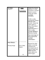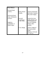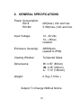
1
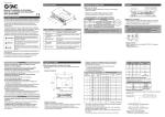
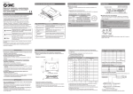
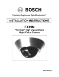
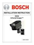
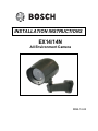
INSTALLATION INSTRUCTIONS EX14/14N All Environment Camera MAN-14-04 IMPORTANT SAFETY INSTRUCTIONS 1. Read these instructions. 2. Keep this instruction. 3. Heed all warnings. 4. Follow all instructions. 5. Do not use this apparatus near water. 6. Clean only with dry cloth. 7. Do not block any ventilation openings. Install in accordance with manufacturer instructions. 8. Do not install near any heat sources such as radiators, heat registers, stoves or other apparatus (including amplifiers) that produce heat. 9. Do not defeat the safety purpose of the polarized or grounding-type plug. A polarized plug has two blades with one wider than the other. A grounding type plug has two blades and a third grounding prong. The wide blade or the third prong is provided for your safety. If the provided plug does not fit into your outlet, consult an electrician for replacement of the obsolete outlet. 10. Protect the power cord from being walked on or pinched particularly at plugs, convenience receptacles, and the power where they exit from the apparatus. 11. Only use attachments/accessories specified by the manufacturer. 12. Use only with the cart, stand, tripod, bracket, or table specified by the manufacturer, or sold with the apparatus. When a cart is used, use caution when moving the cart/apparatus combination to avoid injury from tip-over. 13. Unplug this apparatus during lightning storms or when unused for long periods of time. 14. Refer all servicing to qualified service personnel. Servicing is required when the apparatus has been damaged in a way, such as power-supply cord or plug is damaged, liquid has been spilled or objects have fallen into the apparatus, the apparatus has been exposed to rain or moisture, does not operate normally, or has been dropped. IMPORTANT For best results, please read this Instruction Booklet prior to installing the EX14 camera. WARNING! CSA Certified / UL Listed CLASS 2 power adaptors must be used in order to comply with electrical safety standards. EU Directives covered by this declaration: 72/9/EC Low Voltage Directives 89/336/EEC Electromagnetic Compatibility Directive Only qualified personnel shall install any surveillance product. Bosch Security Systems, Inc. will not be responsible for injuries or damages resulting from the improper installation or use of any product sold by Bosch Security Systems, Inc their agents, distributors or dealers. NOTE: This equipment has been tested and found to comply with the limits for a digital device, pursuant to part 15 of the FCC rules. These limits are designed to provide reasonable protection against harmful interference in a residential installation. As part of its’ normal operation this device can generate radio frequency energy and if not installed and used in accordance with the installation manual may cause interference to radio communications. However, there is no guarantee that interference will not occur on a particular installation. If the device does cause interference to radio or television reception the user is encouraged to try to correct the interference by one or more of the following measures: 1) Fit Ferrite beads on all cable to and from the power supply box, within the box walls. 2) Route the composite cable between the camera and the power supply in steel conduit piping over the entire run of the cable up to and including connection to a deep conduit base fitted under the camera and a conduit fitting adaptor in the wall of the PSU box. 3) Contact BOSCH Service Center for further advice. INDEX – EX14/14N Page Description...................................................1 Unpacking....................................................2 Parts List......................................................2 Items Required for Installation.....................2 Initial Preparations .......................................3 Guidelines....................................................3 Section 1. Camera Mounting .......................4 Section 2. Camera I/O Connections ............9 Section 3. Input Power Connections………10 Section 4. Camera/LED Adjustments ........12 Section 5. Troubleshooting Guide .............15 Section 6. General Specifications..............18 DESCRIPTION The EX14 All Environment Camera consists of a twopiece injection molded watertight housing with a tough polycarbonate viewing window. This compact camera meets IP66 ratings for applications wherever environmentally sealed CCD cameras are required. The camera is especially suited for wash down applications in food processing and industrial clean-room installations. The EX14 can be ordered in monochrome or color versions, featuring varifocal and auto-iris IR-optimized lenses. A rigid nylon mounting bracket is also included with the camera. A voltage regulator circuit allows for 12V dc or 24V ac operation and a range in between. It also provides protection from voltage surge, transient spikes, and reverse voltage. The EX14N comes with integrated Infra-Red illumination to permit imaging in 0 Lux conditions The EX14 is available in several models to meet individual requirements or specific needs. See the Light. Get the Picture.™ 1 UNPACKING Care should be taken when unpacking the shipped unit. Check the parts list and confirm all items have been located. Inspect the equipment thoroughly to ensure nothing was damaged in transit. Contact BOSCH Service Center if a problem is noted, see the rear page of this booklet for contact numbers. PARTS LIST (items supplied with unit) • • • • • EX14 Camera or EX14N integrated infraRed Two Allen Keys One Mounting Bolt Nylon Mounting Bracket(supplied with camera) Installation Instructions booklet ITEMS REQUIRED FOR INSTALLATION (not supplied with unit) • mounting hardware & tools 2 INITIAL PREPARATIONS • The camera’s voltage regulator board (VRB) accepts an input voltage of either 12Vdc or 24Vac, and a range in-between, from a regulated power supply. • The VRB automatically switches between ac or dc inputs, therefore no internal wiring changes are necessary to accommodate these input voltages. • Determine the optimum location for the camera. Section 1: Camera Mounting • All cameras have been tested prior to shipment. GUIDELINES The installation of the EX14 Camera is shown in Sections 1 to 4 listed below. It is important that these steps are followed in sequence: 1. 2. 3. 4. Camera Mounting Camera I/O Connections Input Power Connections Camera/LED Array Adjustments 3 1. CAMERA MOUNTING Caution: Install the mounting bracket with the appropriate screws or drywall anchors to suit the mounting surface. Select a suitable location that is protected from accidental damage or tampering, and environmental conditions that could exceed the camera’s general specifications. See page 18. Caution: Ensure the selected location is protected from falling objects, accidental contact with moving objects, and unintentional interference from personnel. Follow all applicable building codes. The following installation guidelines must be followed: • Locate the camera such that it cannot be easily interfered with, either intentionally or accidentally. • Select a mounting surface capable of supporting the combined weight of the camera and its mounting hardware under all expected conditions of vibration and temperature. • Secure all cabling. 4 Power Input & Video Output Cable Mounting Surface EX14 Camera Camera Angle Bracket Mounting Bracket Mounting Hardware Tighten this bolt after the camera viewing angle has been set FIGURE 1 – 1 Camera and Bracket – Mounting Details 5 Warning: this apparatus must be securely attached to the wall or ceiling in accordance with installation instructions. Failure to follow installation instructions may results in injury/death. Select a suitable location that protects the camera from accidental damage, tampering and environmental conditions exceeding the specifications of the camera to be mounted. Caution: Ensure the selected location is protected from falling objects, accidental contact with moving objects and unintentional interference from personnel. Follow all applicable building codes. The following installation guidelines must be followed: • Locate the bracket such that it cannot be easily interfered with, either intentionally or accidentally. • Select a smooth, flat mounting surface to ensure proper sealing. The surface must also be capable of supporting the combined weight of the camera and mounting hardware under all expected conditions of vibration and temperature. • Secure all cabling. • Installation should only be performed by skilled personnel 6 Hardware required: • For wall mount: 1. 10 x 2” Round Head Bolt, Qty = 2 2. ¼” Flat Washer, Qty = 2 Tools required: • Drill • Stud Finder • 5/32” Drill Bit • # 2 Screwdriver Mounting instructions for wall and ceiling mount: Camera is intended to be securely mounted to a wall using the mounting bracket supplied with the enclosure. Camera has been evaluated for wall mounting using the following wood screws secured into a 2x4 stud under ½” drywall. Wood screws: • wood screws with washer, #10, 2” long • flat washer. Camera has not been evaluated requirements using other mounting kits. for safety Installation (Wall Mount) • Locate stud in the wall and mark outside edges of stud. • Using wall mount bracket as a template, align the mounting hole with the center of the stud. 7 • Marking the point on the wall in the center of the hole where mounting screw will be positioned. • Remove the wall mount bracket and using a 5/32” drill bit, drill a pilot hole at the marked point. • Align the ceiling/wall mount bracket mounting hole with the hole drilled in the ceiling/wall • Using a socket and driver, secure the ceiling/wall mount bracket by screwing the #10 screw with washer securely into the stud. • Use second #10 screw and washer to secure the remaining mounting holes. • Installation is complete. 8 2. CAMERA I/O CONNECTIONS Connect the Power Input (ac or dc) to the camera as shown below. Wires are not polarity dependent. Connect the Video Out BNC connector to a monitor. Video Out Power Input Figure 2 – 1 Camera I/O Connections 9 3. INPUT POWER CONNECTIONS The camera unit is pre-connected with an electrically isolated power board for 24Vac or 12V dc operation with no wiring change or wiring polarity. See Figure 3-1. Note: Input voltage is 12VDC to 24VDC for DC input. The AC input range is 12VAC to 24VAC. Power IN Power OUT FIGURE 3 - 1 12VDC or 24VAC Electrically Isolated Board 10 Power to LED Array Photocell Adjustment 12V Enable Power Input FIGURE 3 – 2 LED Array Power Board 11 4. CAMERA/ LED ARRAY ADJUSTMENTS Focus and Zoom Adjustments Loosen and tilt back the camera’s top cover to access the lens for adjustment. Step 3.1 - Loosen the lens setscrews for focus/zoom adjustments. See Figure 4-1 on page 13. Step 3.2 - The setscrew for N ←→ ∞ is used for image focus. Step 3.3 - The setscrew for T←→ W is used for telephoto or wideangle settings. Step 3.4 - Re-tighten the setscrews after focus adjustments have been completed. The LED Array brightness has been set at the factory before shipment. For photocell brightness adjustment refer to Figure 3-2 on page 11. 12 W T N Loosen this set-screw for Focus Adjustment Loosen this set-screw for Telephoto or Wide Angle Adjustment FIGURE 4 – 1 Focus and Zoom Adjustments 13 Use a Neutral Density filter or Infra-Red Pass filter to cover the lens during focusing to simulate low light conditions on scene for correct 24-hour focusing. For camera with varifocal lens, the camera should be focused with the lens iris fully opened to simulate the worst possible depth of field. Using a Neutral Density filter or Infra-Red Pass filter will ensure the iris is fully open for correct setup and adjustment. Note that statement above is applicable only for Day/Night or IR version cameras. 14 5. TROUBLESHOOTING GUIDE PROBLEM No Video POSSIBLE CAUSE 1. Power Supply: -Connections…. -Voltage Range... LIKELY SOLUTION Check input power connections at the cable leads. Check for loose wires. If connected to DC, check input voltage range of 12 – 24V. If connected to AC, check input voltage range of 12 – 24V. Measure the voltage and current at the Input Power Cable. The current should be >.02A and <1.0A. 15 No Video (cont’d.) 2. Video Connections Determine if wiring polarity at “Video Connector” terminal block is correct. Check the cable and BNC connector. If still no video, connect the camera directly to the monitor. Check the video signal. If okay, the problem is with the interconnections. If still no video, contact BOSCH Service Center. See rear page of this manual for contact information. ______________ Poor Picture ___________ Snowy Image Poor Video Signal 16 ________________ Ensure the video cable is correctly matched and terminated with 75 ohms at each end. Make sure the video cables are similar types. Poor Picture Snowy Image (cont’d.) Horizontal Scan Lines, Rolling Up or Down Noisy Power Supply Check connections. Relocate or replace the power supply. Ground Looping on video cable Check the coax cable shield is not touching ground, e.g. at couplings. Check video polarity. Low voltage Check voltage at the input power cable. Must be >10.5V dc or >12V ac. Negative, scrambled, or faded image 17 6. GENERAL SPECIFICATIONS Power Consumption: EX14 EX14N 2W(max.) Vdc and Vac 5.3W(max.) Vdc and Vac Input Voltage: 12 - 24 Vdc, 12 – 24Vac, isolated Enclosure (housing): ABS/Nylon (sealed to IP66) Viewing Window: Tempered Glass Dimensions: H: 3.35” (85mm) W: 3.35” (85mm) L: 7.10” (180mm) Weight: 0.7kg (1.5 lbs. ) Subject To Change Without Notice. 18 Notes: 19 Notes: 20 Notes: 21 Americas Bosch Security Systems, Inc. 850 Greenfield Road Lancaster, Pennsylvania 17601 USA Telephone+1 888-289-0096 Fax +1 585-223-9180 Email: [email protected] www.boschsecurity.us Europe, Middle East, Africa: Bosch Security Systems B.V. P.O. Box 80002 5600 JB Eindhoven, The Netherlands Phone: + 31 40 2577 284 Fax: +31 40 2577 330 [email protected] www.boschsecurity.com Asia-Pacific: Bosch Security Systems Pte Ltd 38C Jalan Pemimpin Singapore 577180 Phone: +65 6319 3450 Fax: +65 6319 3499 [email protected] www.boschsecurity.com © Bosch Security Systems, Inc. 2009; Data subject to change without notice.