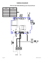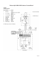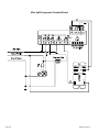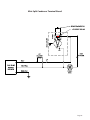
1
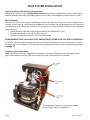
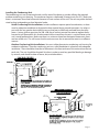
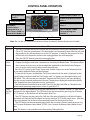
SPLIT SYSTEM
OWNER’S MANUAL
TO BE USED WITH YOUR SYSTEM’S
UNIT SPECIFIC INSTALLATION GUIDE
The Coolest Thing In Wine Storage
Copyright © 2010. WhisperKOOL. All rights reserved.
This manual, the product design, and the design concepts are copyrighted by WhisperKOOL, with all rights reserved. Your rights
with regard to the hardware and manual are subject to the restrictions and limitations imposed by the copyright laws of the
United States of America. Under copyright laws, this manual may not be copied, reproduced, translated, transmitted, or reduced
to any printed or electronic medium or to any machine-readable form, for any purpose, in whole or in part, without the written
consent of WhisperKOOL.
Every effort has been made to ensure that the information in this manual is accurate. WhisperKOOL is not responsible for printing
or clerical errors.
WhisperKOOL reserves the right to make corrections or improvements to the information provided and to the related hardware at
any time, without notice.
Vinothèque and WhisperKOOL are registered trademarks, and ECE is a trademark of Vinothèque Wine Cellars. All rights reserved.
Mention of third-party products is for informational purposes only and constitutes neither an endorsement nor a recommendation. WhisperKOOL assumes no liability with regard to the performance or use of these products.
Rev. 081310
Page 2
GSM-01 081310
TABLE OF CONTENTS
Introduction ............................................................................................................. 2
Receiving & Inspecting The Unit.................................................................................
3
Preparing the Wine Cellar ......................................................................................47
Installation ...................................................................................................................6 7
Remote Keypad ...............................................................................................................
9
Ducted Installation ................................................................................................ 10
Liquid Measuring Thermometer ...............................................................................
11
System Operation ......................................................................................................12
Control Panel Operation ...............................................................................................
13
Maintenance Schedule .................................................................................................
16
Troubleshooting Guide .................................................................................................
17
Wiring Diagrams .............................................................................................................
22
Technical Assistance .........................................................................................................
26
Installation Terms and Conditions .............................................................................
27
Page 1
INTRODUCTION
Customer Service
Thank you for purchasing a WhisperKOOL split system. We strive to provide the highest quality products
and the best possible customer service. If you have any questions about your WhisperKOOL unit, please call
us at 1(800) 343-9463 or visit www.whisperkool.com.
Using this Manual
This Owner’s Manual is intended to be a general WhisperKOOL split system installation and maintenance
guide. Please use the supplied unit specific installation guide in conjunction with this manual. In order to
ensure the longevity of your cooling system, the equipment should be installed properly and have a proper
care and maintenance schedule. Please read and review this manual carefully and keep it for future reference.
What is a WhisperKOOL Split System?
Specialized refrigeration systems designed for one purpose only: to maintain the optimal temperature and
humidity levels conducive to the proper storage and aging of fine wines. Split systems produce minimal
in-cellar noise and have the most lenient exhaust requirements. An exterior housing is required for outdoor
condensing unit installations.
How Does a WhisperKOOL Split System Work?
Similar to the air conditioning systems used for homes, the evaporator and condensing units are installed
in separate locations and are connected by a line set. The evaporator portion is commonly installed in the
wine cellar, with the condensing unit located either outside or in a remote indoor location.
Page 2
GSM-01 081310
RECEIVING & INSPECTING THE UNIT
Customer Warranty Registration
PLEASE COMPLETE AND RETURN THE WARRANTY CARD UPON RECEIPT OF THE UNIT.
By completing the Product Registration Card, you will be confirmed in our customer database ensuring that
your information is on file to help you obtain efficient warranty service. Please refer to page 25 for complete
terms and conditions, warranty guidelines, and policy for your WhisperKOOL split system.
Note: WhisperKOOL split systems are manufactured in the USA and tested prior to shipment.
Receiving and Inspecting the System
• Lift only at the designated hand hold locations on the shipping container or fully support the unit
from underneath. A shipment may include one or more boxes containing accessories.
• Before opening the container, inspect the packaging for any obvious signs of damage or mishandling.
• Record any discrepancy or visual damage on the Bill of Lading before signing.
Review the Packing Slip to Verify Contents
• Check the model number to ensure it is correct.
• Check that all factory options ordered are listed.
If any items listed on the packing slip do not match your order information, contact WhisperKOOL Customer
Service immediately at 1-800-343-9463.
Check your shipment for the following contents:
• Evaporator Unit
• Condensing Unit
• Unit Specific Installation Guide
• Registration / Warranty Card
• Sight Glass
• Filter Drier
• Accessory Kit
• Mounting Hardware
Note: Refer to the Unit Specific Installation Guide (USIG) for a detailed packing list for your specific split
system order.
Please leave the WhisperKOOL system in its original boxes until you are ready for installation. This will allow
you to move the product safely without damaging it. WhisperKOOL highly recommends that you save your
boxes and all packaging materials. They provide the only safe means of transporting/shipping the system.
When you are ready to remove the product from the boxes, refer to page 6 for installation instructions.
Page 3
PREPARING THE WINE CELLAR
The performance and life of your WhisperKOOL system are contingent upon the steps you take in preparing
the wine cellar.
Note: Improperly preparing your enclosure or incorrectly installing your WhisperKOOL system may cause
unit failure, leaking of condensation, and other negative side effects.
IT IS HIGHLY RECOMMENDED THAT YOU OBTAIN THE ASSISTANCE OF A
WINE STORAGE PROFESSIONAL.
Wine storage professionals work with licensed contractors, refrigeration technicians, and racking companies
to build well-insulated, beautiful, and protective wine cellars. WhisperKOOL has put together some useful
tips to assist in the installation process. Our recommendations are meant to act as a guide in the process of
building a proper enclosure. Your intended location may have specific needs that we do not address.
Wall & Ceiling Framing
Build wine cellar walls using standard 2x4 or 2x6 construction methods and ceiling joists following the
guidelines of local and state codes in your area. As a general rule, the thicker the walls and the higher the
insulation factor in your cellar, the better it will be at maintaining a consistent temperature.
Insulation
Insulation is REQUIRED with the use of the WhisperKOOL product. Standard fiberglass or rigid foam insulation is normally used in cellar construction or, in some cases, “blown-in” insulation is used. It is very important that all walls and ceilings are insulated to keep the cellar temperature as consistent as possible during
the summer and winter months. The R-factor, or quality of insulation, is determined by the rate at which
heat passes through the insulation. The higher the R-factor, the more resistant the insulation is to conducting heat. Using higher R-values in insulation will lower your operating costs and unit run time.
Vapor Barrier
Vapor barrier is REQUIRED to prevent the intrusion of water vapor so that the cellar can be kept at the correct temperature and humidity. 6 mm plastic sheeting (recommended) should be applied to the warm side
of the cellar walls. The vapor barrier must also be applied to the outside walls and ceiling. If it is impossible
to reach the outside, then the plastic must be applied from within the cellar. The most common method is
to wrap the entire interior, leaving the plastic loose in the stud cavity so the insulation can be placed between each stud. All of the walls and ceiling must be wrapped in plastic for a complete vapor barrier.
In areas of high humidity, such as Southern and Gulf States, the vapor barrier will prevent infiltration of
warm moist air. The moist air can cause mold to form, and standing water in drain pans promote microbial
and fungal growth that cause unpleasant odors and indoor air quality problems. If mold is found, remove it
immediately and sanitize that portion of the system.
Door and Door Seal
An exterior grade (1 3/4”) door must be installed as a cellar door. It is very important that weather stripping
is attached to all 4 sides of the doorjamb. A bottom “sweep” or threshold is also required. The door must have
a very good seal to keep the cool cellar air from escaping out of the cellar. One of the most common problems with cooling units running continually is the door not sealing properly. In cases where glass doors are
used and the room size is close to the recommended unit size, the next larger size WhisperKOOL should be
used. This will compensate for the insulation loss due to the inefficient door.
Page 4
GSM-01 081310
Unobstructed Airflow
Unobstructed airflow to and from both the evaporator and condenser is a critical factor in the system’s overall performance. Make sure there is a 3 ft. horizontal clearance in the front of both units. This will assure that
the air can circulate in an efficient manner. Avoid any attempt to camouflage the evaporator by installing
racking in front of the unit. This will restrict the airflow and reduce system performance.
In-Cellar Mounting
If you are mounting your evaporator in the cellar, it should be mounted within 18“ of the top of the room in
order to achieve sufficient cooling. As the room cools down, the warm air will rise to the ceiling. Mounting
the evaporator high in the room will create a consistently cool environment by capturing the warm air and
replacing it with cool air. Mounting the evaporator low in the room will result in a temperature variation in
the room due to the unit’s inability to draw warm air from the ceiling of the cellar to the unit itself.
Ducting
Some systems are designed to have the air exchange happen out of the cellar using duct work. This allows
the evaporator unit to placed in a variety of positions around the cellar and in some models up to 25 duct
feet away. The return air (from cellar to unit) needs to be located low in the cellar with the supply air (from
unit to cellar) should be located high in the cellar. This greatly increases the efficiency of the cooling system
by allowing the cold air travel throughout the entire cellar space and absorb as much heat as possible.
How to Build a Wine Cellar Instructional Video
WhisperKOOL has a construction tutorial available on line at www.whisperkool.com, or you can call 1-800343-9463 and contact our Customer Service (ext. 799) or Sales Department (ext. 751) for information on
how to obtain a DVD version. This tutorial will walk you through the steps of constructing a properly built
wine cellar and the installation of our WhisperKOOL product line.
Page 5
SPLIT SYSTEM INSTALLATION
General Installation Guidelines and Instructions
WhisperKOOL requires that a certified HVAC technician install and charge all split systems. Please take a
moment to review state and city building codes to ensure the safe and proper installation of the system.
Electrical Needs
WhisperKOOL split systems requires a dedicated 110-volt 20-amp circuit. The system draws a large amount
of amps at initial start up. By designating a dedicated circuit breaker, you will guarantee that the system has
enough power to run effectively. Contact an electrician for assistance with the installation of this dedicated
electrical circuit:
1. Match the electrical outlet to the plug provided on the WhisperKOOL unit.
2. Provide a dedicated circuit and wiring for the unit.
3. Provide a weatherproof plug for units mounted outside.
WE RECOMMEND THAT YOU DO NOT USE A GROUND FAULT INTERRUPTER (GFI) WITH THIS PRODUCT.
In case the system should lose power, press the reset button and attempt to turn the unit back on. Check
the home/main circuit breaker. If the unit does not respond properly, refer to the Troubleshooting section
on page 17.
Condensing Unit Preparation
Note: The condensing unit is shipped with a protective foam pad/ block to prevent damaging tubing
against the condenser coil fins. Please ensure that this pad is removed prior to operation.
*A Low Ambient Control is used on most models,
a Fan Cycling Switch is used otherwise.
Page 6
GSM-01 081310
Installing the Condensing Unit
The condensing unit can be mounted inside a utility area of the home or outside utilizing the required
outdoor condensing unit housing. The condenser requires a dedicated 20 amp circuit, non-GFI. Make sure
there is a minimum three-foot horizontal clearance in front and rear of the unit. The unit may either be hard
wired or plug-in depending on local electrical codes.
Inside Condensing Unit Installations: Inside installations require special consideration, as there
must be adequate ventilation to dissipate the heat created during normal operations. An exhaust
port with fan may need to be installed to ensure that heat is effectively removed from the utility
room. A return grille or provision for 500 - 600 cfm of cool air to enter the room to replace the exhausted air will accomplish this. Unobstructed airflow to and from the unit is a critical factor in the
unit’s overall performance. Make sure there is a minimum three-foot horizontal clearance in front
and rear of the unit. This will assure that the unit can move the air around the room in an efficient
manner.
Outdoor Condensing Unit Installations. You must utilize the exterior condensing unit housing for
outdoor installations. Place the condensing unit on a solid foundation in a location with adequate
ventilation. There should be three feet of clearance in the front and rear of the unit and one foot on
each side. The unit should be elevated 18 inches in order to avoid any possible flooding or damage
by animals, and should be clear of leaves, dirt, and other debris.
Page 7
SPLIT SYSTEM INSTALLATION (cont’d)
Installing the Evaporator Unit
Please refer to the supplied Unit Specific Installation Guide
for detailed evaporator installation guidelines.
Head Pressure Control, Low Ambient Control Switch, Fan Cycling Switch:
These switches are used to cycle the condenser fan at low ambient temperature conditions. If your unit is
equipped with a Low Ambient Control, set the switch to 170 psig for cut-in and 70 psig for the differential.
Further adjustment may be needed. Verify the settings via refrigeration manifold gauge and perform the
final adjustments to the readings on the gauge manifold. If your condensing unit is not equipped with a Low
Ambient Control, it features a pre-set Fan Cycling Switch.
Refrigeration Lines
A 1/4 inch O/D copper “liquid line” and a 3/8 or 1/2 inch O/D copper “suction line” connect the two units.
The refrigerant drier and the sight glass shall be installed (in that order) in the direction of the refrigerant
flow in the liquid line between the condensing unit and evaporator. Enclose the suction line in a cellular
insulation ½” wall thickness Armaflex (brand name) or equal to reduce heat transfer.
Wiring System
The compressor is controlled by a “pump down cycle,” therefore, no wiring between the condensing unit
and evaporator unit is necessary. Wire the system in accordance with local codes and the enclosed wiring
diagrams (pg 22). The evaporator unit requires a standard 20 amp circuit, non-GFI. A dedicated circuit is not
mandatory, but recommended.
Charging the System (by Certified HVAC technician)
After all the piping is complete:
Open both of the service valves on the condensing unit (the unit is pressurized with nitrogen, and there
should be an audible sound of gas escaping through the service ports).
With electrical power connected to the evaporator unit, energize the solenoid valve (pressurize with dry
nitrogen) to 200psi. Leak test all fittings. The system must hold 200psi for 30 minutes.
If no leaks are found, leave the solenoid valve energized and evacuate the system through both the liquid
and suction service ports. Using a high vacuum pump, evacuate to 200 microns, measuring the vacuum
with a digital micron gauge. When evacuation is complete, break vacuum and pressurize with liquid R-134A
refrigerant.
With the electrical power turned on to the condensing unit, and the evaporator unit running, slowly feed
liquid refrigerant (R134A) into the suction service port. As the suction pressure rises to 15 PSIG, the condensing unit will start. Slowly feed refrigerant while maintaining a pressure above 10 PSIG to prevent the compressor from short cycling. Slowly feed refrigerant with the compressor running until the sight glass is clear
of all bubbles. Do not exceed 3.5 lbs of refrigerant. Check superheat at the evaporator outlet. Superheat
should be at 10°-12°. Check the compressor crankcase temperature after 30 minute run time – it should be
hot (115°to 140°). If it is cooler, superheat is too low. Adjust TXV to recommended superheat.
Allow the system to operate for one hour and then check the refrigerant level in the sight glass again. Additional refrigerant may be required as the temperature of the enclosure is lowered to approximately 55°F or
the ambient temperature at the condensing unit rises above the temperature at which the unit was initially
charged. Depending on temperature, the “high side” should be approximately 175 lbs, and the ”low side” 28
lbs or more to keep the evaporator from icing. It is recommended while charging to use a digital refrigerant
scale for better accuracy in measuring the amount of charge.
Page 8
GSM-01 081310
REMOTE KEYPAD: INSTALLATION AND CONFIGURATION
If you have a system with a remote keypad, please review this section for installation.
Note: 50 feet of communication line is included, the keypad can be installed up to 300 line feet away. Longer lengths of communication line can be ordered by calling 1-800-343-9463 ext. 751.
Run your communication line to the desired location, be sure not to have any harsh kinks in the lines route.
Attach the connection wire as shown below, with the red wire in the upper connection slot and the black
wire in the lower slot. It is also important to run your bottle probe line at this time,
Red Wire
Black Wire
To install the remote keypad box, remove the rear mounting bracket and secure the bracket to the wall in
the desired location. When running the communication line through a wall, be sure to run the line in the
rear mount position and insert the supplied plug in the side hole on the box. Reattach the keypad box to
the bracket.
TM
TM
TM
TM
Connection wire in Side Mount configuration
Connection wire in Rear Mount configuration
Page 9
DUCTED INSTALLATION
Ducting the supply and return air to the cellar creates a virtually silent cellar space and also maximizes cellar
capacity. It is absolutely crucial to only use insulated duct work as it minimizes cooling loss, prevents sweating, and reduces noise. Failure to use insulated ducting will cause the unit to run excessively and greatly
shorten its lifespan.
Note: Do not exceed a total of 25 duct feet between the evaporator and cellar vent, this means a total of 50’
combined for both the supply and return lengths.
Avoid crimping the flexible ducts. This chokes down the inside area and reduces the airflow causing the unit
to lose efficiency. Be sure all ducts and surfaces in contact with the airflow are insulated and have a vapor
barrier on the outside.
Un-insulated ducts and surfaces cause bare, exposed metal surfaces to sweat, further degrading the
insulation and equipment cooling capacity.
General Duct Recommendations:
• Provide support for the flexible duct to prevent sags and bends
• Stretch out the duct to make a smoother interior, which reduces air resistance
• For 90° bends, use a 90° adjustable elbow (Ell)
• Do not squeeze or reduce the inside diameter of the ducts, which reduces airflow
• Use short and straight duct work where possible
• Remove the grilles and panels from the openings to connect the duct work
• Check that all fan blades move freely
• Keep air paths free of loose foreign objects and debris
• Connect the round flexible ducts to the WhisperKOOL system using the duct collars provided with
the duct accessory kit
• Pull the outer plastic wrapping and insulation away from the end of the duct to expose the reinforced
inside duct liner
• Fasten the duct collar using tie straps or clamps around the inside liner
• Secure the duct collar to the unit using the screws provided. Take care to not damage or bend the
gasket
• Use approved duct tape to seal all joints
Do not clamp around the outside insulation,
as it will compress and loosen over time.
Note: When performing a ducted installation, it is crucial
to not forget about routing the bottle probe into the cellar.
The system must have the sensing bottle in the cellar to
maintain the cellar environment.
Possible ducting
configuration.
Page 10
GSM-01 081310
LIQUID MEASURING THERMOMETER
Most WhisperKOOL systems come equipped with a liquid temperature measuring thermometer probe . This
self calibrating probe contains a sensor chip, which actually communicates back and forth to the thermostat.
This results in a consistent liquid temperature as air temperature fluctuates
Measuring liquid temperature has a couple unique advantages:
1. The temperature of the wine can be more precisely controlled, ensuring a more consistent overall
temperature.
2. The system will switch on/off less often, extending cooling system life.
To use the thermostat:
1. Fill an empty wine bottle 3/4 full with room temperature tap
water
2. Press bottle probe securely into bottle
3. Place the bottle with probe into a level rack space. Avoid pulling too much on the probe cord, it may become disconnected
resulting in non-operation of the unit.
Remember: The WhisperKOOL System maintains cellar environment based on the liquid temperature. It is ideal to place the
probed bottle lower in the racking so that it is not near cold supply
air.
Note: When performing a ducted or remote installation, it is crucial to not forget about routing the bottle probe into the cellar. The
system must have the sensing bottle in the cellar to maintain the
cellar environment.
Page 11
SYSTEM OPERATION
Initial Start-Up
When power is applied to the unit, the control will
briefly display all symbols, and the Snow Flake
symbol will be displayed (if unit is calling for cooling). There may be a brief delay prior to the evaporator fan turning on, as the fan will not turn on until
the evaporator probe temperature drops to the
perspective start temperature (below 70°F). When
the evaporator fan is activated the Fan symbol will
be displayed. The temperature control feature for
the evaporator fan is a feature applicable to WhisperKOOL. This is the Advance Product Safety Technology (APST), which ensures that in the possible
event of a cooling deficiency, the heat from the
indoor fan will not raise the temperature of the wine
cellar, which could otherwise have an adverse effect
on the wine aging process.
Low Ambient Conditions
If the condensing unit is installed outside (which will
allow the condenser to be exposed to low ambient
temperatures), the condenser fan may cycle on and
off. The purpose of the fan cycling is to maintain
the system high side pressure, which will ensure
an adequate refrigeration process. The fan cycling
process is accomplished by way of a Johnson Control
attached to the condensing unit.
Normal System Cycle
After the bottle probe has reached the set point (all
units are shipped with the set point of 55°F and a differential of 1°F), the compressor and the condenser
fan will turn off, but the indoor fan will continue to
run for about 5 minutes, which is a feature of the
WhisperKOOL Humidity Management (WHM) system. The WHM is an adjustable feature which allows
the customer the convenience of managing the humidity enhancement of their wine cellar. The WHM
is one of the many Customer Preference Selection
features which allow the customer the ability to fine
tune the controls.
Remote Control Panel (standard on ducted units)
The remote keypad is designed to give the user the
ability to monitor and change cellar conditions when
the evaporating unit is placed in a remote location
outside of the cellar.
Bottle Probe Failure Protection
In the event that a bottle probe should fail, the APST
(Advance Product Safety Technology) will automatically transition the Refrigeration Compressor cycles
to a pre-determined time series (based on detailed
laboratory testing), which will ensure that the product is kept within the safe range.
Anti Short Cycle
The Anti Short Cycle ensures that the unit will remain off for a period of 5 minutes after the unit has
reached the set point to allow the pressure in the
refrigeration system to equalize prior to starting the
compressor.
Anti Frost Cycle
The Anti Frost Cycle is a precautionary measure, as
icing or frosting of the coil does not occur during
normal operation. The system will go through a
defrost cycle every 4 hours. During the defrost cycle,
the indoor fan will provide air flow across the indoor
coil, which will evaporate any frost accumulation.
Page 12
GSM-01 081310
CONTROL PANEL OPERATION
Defrost
Compressor
Evaporator Fan
Cellar “Pre-Chill” Button 3-5
Energy Reduction
Button 1
Hi Bottle Temp History & Scroll
Button 1
Energy Reduction
Low Bottle Temp History & Scroll
Button 1
Set Button
•View Set Point 1
•Change Set Point 3-5
•SET + Down = CPSM 3-5
•Reset Hi & Lo Button 3-5
Control “ON/OFF” Button
•Turns the Cooling Unit
“ON/OFF” 1
ALARM
Pre-Chill Display
Condenser Fan
Note: The 1 or the 3-5 stands for the amount of time (in seconds) that the button must be held.
Button
Normal Functions
ON/OFF • The ON/OFF button allows the customer the convenience of turning the refrigeration system
ON or OFF, from the control panel. This feature does not disconnect power from the unit, and
the condenser fan will continue to run in the OFF position. In order for the power to be shut
off from the unit, the power cord must be unplugged from the wall receptacle.
• Press the ON/OFF button once for button application.
Up and • Use these buttons to scroll up or down the CPSM menu.
Down
• Displays the Highest and Lowest temperature sensed by the Bottle Probe. This feature allows
Arrows
the customer instant access to the recorded data applicable to the Bottle Probe Temperatures, it can be easily reset to reflect current temperatures.
1. Press the “UP” arrow, or the “Down” arrow once, and the Highest or Lowest Temperature (Hi/
Lo) sensed by the Bottle Probe, will be displayed.
2. To reset the Hi/Lo, press and hold the “Set” button when the Hi/Lo value is displayed on the
Digital Display, continue to hold the “Set” button until “rst” appears on the digital display and
then blinks. This will erase the past recorded “Temperature Data History” and start recording,
from the current time and temperature, forward. Temperatures displayed would reflect Bottle
Probe Temperatures from that point in time, and beyond.
3. The Hi/Lo feature should be reset at initial “Start-Up” and after the Cellar or Cabinet has obtained normal operating temperatures, which is generally 55°F.
Cellar
The CPC Feature is activated by pressing the Up button for 3-5 seconds, and the CPC logo will be
PreChill displayed on the digital display. The CPC feature can be terminated by pressing the Up button
(CPC)
for 3-5 seconds, or the feature will self terminate after 6 hrs.
1. The (CPC) Feature may be used to Pre-Chill the Cellar prior to loading it with Warm Product.
The feature will shift the Set Point down to a lower setting of 52°F, for the next 6 hours. After the
6 hour time period, the Set Point will automatically return to the original Set Point.
2. The CPC feature can be conveniently adjusted to the customer’s specific needs, by accessing
the “Customer Preference Select Mode” (CPSM). See Customer Preference Select Mode Instructions.
Note: This feature is not available on the Remote Key Pad application.
Page 13
Energy
Reduction
(ER)
Set
Button
CPSM
Mode
1. The ER feature can be used to save energy and aids in extending the life of the system.
2. The ER button is located at the top L/H side of the control. The ER feature is activated by
pressing the ER button one time, and the ER logo will appear on the digital display.
3. The purpose of the ER feature is to reduce energy cost, by shifting the Set Point up by 4 degrees, which will allow the cooling system to run for shorter periods of time, resulting in a reduction in energy cost.
4. The ER feature allows for Energy Savings at any time - During periods of high ambient temperatures, vacations or business travel.
5. To deactivate the ER feature, press the ER button one time, and the ER logo will turn off.
6. The ER feature can be conveniently adjusted to the customer’s specific needs, by accessing
the “Customer Preference Select Mode” (CPSM). See Customer Preference Select Mode Instructions.
Note: This feature is not available on the Remote Key Pad application.
1. Press the “Set” button once and it will display the Set Point. After approximately 5 seconds,
the display will return to normal operation and display the Bottle Probe temperature.
2. Press and hold the “Set” button for 3-5 seconds until the set point is displayed and the °F symbol starts blinking. Next press the “UP or Down” arrows to change the Set Point. Next press the
“Set” button once and the Set Point numbers and the °F on the display will blink to confirm the
new Set Point setting.
3. Press and hold the “Set” button during the display of the Hi/Low “Temperature Data History”
(hold button unit “rst” blinks on display), and it will erase the past recorded data file and start
recording, from the current time and temperature.
4. Press the “Set” and the “Down Arrow” buttons simultaneously, for 3-5 seconds, and you will access the “Customer Preference Selection Mode” (CPSM). The CPSM allows the customer to “Fine
Tune” the Control Operating System to their applicable choice.
Press the “Set” and the “Down Arrow” buttons simultaneously, for 3-5 seconds, and you will access the “Customer Preference Selection Mode” (CPSM). The CPSM allows the customer to “Fine
Tune” the Control Operating System to their applicable choice.
The following CPSM options are available for adjustment:
Fon – Humidity Management Enhancement: This parameter is normally set at 5, which should
provide adequate relative humidity for the cellar.
• An increase in this parameter will increase the Humidity Enhancement (%RH), and a decrease
in the parameter will decrease Humidity Enhancement (%RH).
• Adjustments should be made in increments of 5, with a maximum of 15, and a minimum of 0.
• After any adjustment to Humidity Enhancement, you should wait a minimum of three days
before making any additional adjustments. This will allow the cellar sufficient time to acclimate to the new setting.
Fof - Humidity Management Enhancement: This parameter is normally set at 1. This parameter
should not be adjusted, as it simply provides an OFF cycle time for the fan, during the compressor OFF cycle. However, the parameter is located within the CPSM as a convenience to the customer, should it need to be adjusted.
Page 14
GSM-01 081310
CPSM
Mode
(Cont.)
CCS – Cellar Pre-Chill Set Point: This parameter is set at 52°f, but can be adjusted to a set point
between 45°f - 67°f.
bLL/Act – Compressor Off or On for Low (bLL) or High (Act) Temperature Alarm: These parameters are set at “n”. With this parameter set at “n” the refrigeration system will continue to operate
normally, if there is a High or Low temperature Alarm. To change this parameter, change the setting to “y”, and the compressor/refrigeration system will shut off during a High or Low temperature Alarm.
Con/Cof – Compressor On time (Con) and Off time (Cof ) with a Probe 1 failure/Alarm. These
parameters are set at Con 40 min/Cof 10 min. In the event that there is a Probe 1 failure/Alarm,
the compressor/refrigeration system automatically starts a predetermined ON/OFF cycle, which
is controlled by the Con and the Cof parameters. The customer can adjust these parameters to
maintain the desired Bottle Probe temperature. During a Probe 1 failure/Alarm, the Bottle Probe
temperature can be monitored by pressing the Up or Down arrow to view the High and Low
Temperature History.
Hes – Differential for Energy Reduction – This parameter is set at 4, which results in a set point
of 58°f during the Energy Reduction mode. A decrease in this setting will decrease the set point,
and an increase in this feature will increase the set point.
Display Alarm Codes
Message
Cause
Outputs
“P1”
Room probe failure
Compressor output acc. to par. “Con” and “COF”
“P2”
Evaporator probe failure
Defrost end is timed
“HA”
Max bottle probe temp alarm
Outputs unchanged
“LA”
Min bottle probe temp alarm
Outputs unchanged
“EA”
External alarm
Outputs unchanged
Page 15
MAINTENANCE SCHEDULE
Monthly
1. Check filters
2. Check for unusual noise or vibration
Quarterly Clean filters:
1. Remove grille/ducting on the evaporator
2. Remove the filter covering the coil
3. Wash with warm water
4. Dry off filter by shaking excess water from filter
5. For ducted applications, replace filer (call WhisperKOOL for replacements)
Page 16
GSM-01 081310
TROUBLESHOOTING
Display Alarm Codes
Message
Cause
Outputs
“P1”
Room probe failure
Compressor output acc. to par. “Con” and “COF”
“P2”
Evaporator probe failure
Defrost end is timed
“HA”
Max bottle probe temp alarm
Outputs unchanged
“LA”
Min bottle probe temp alarm
Outputs unchanged
“EA”
External alarm
Outputs unchanged
Fault
Cause
Solution
Water leaking from unit
1. Condensate drain
clogged
Clear out drain
2. Evaporator coil
frozen
Clean the coil and / or fan wheel
3. Drain line improperly
installed
Call a CERTIFIED HVAC service technician.
Wine cellar temperature above thermostat set point
1. Large quantity of warm
wine placed in cellar
Allow time for wine to cool
2. Wine Cellar Door left
open for long period.
Close Door. Allow time for wine to cool.
3. No power to either
evaporator or condensing
unit
Is the thermostat display illuminated?
If not, check power supply switch, if equipped. Ensure it is in the
ON position.
If on, check to see in the breaker is tripped.
If tripped, reset and check display.
Check breaker to condensing unit. If tripped, check to see if compressor is hot – too hot to touch. If so, allow to cool for one (1)
hour before resetting breaker.
After cooling, reset breaker and note whether it remains set or
trips off. If it trips, call a CERTIFIED HVAC service technician for
repair.
Page 17
If the breaker remains set, check to see if compressor is
running and condenser fan turns on.
After compressor runs a few minutes, check the refrigerant
“sight glass” in the ¼” copper tubing. Look for bubbles.
If no bubbles are present and compressor is running,
refrigerant system is running OK.
If bubbles are present, system is low on refrigerant.
A CERTIFIED HVAC service technician will have to locate and
repair any refrigerant leaks, then add refrigerant.
Condenser fan should come on either immediately on
compressor start or after sight glass gets warm.
If not, compressor will trip off on high pressure safety
control, reducing capacity and possibly tripping the
breaker.
In this event, CERTIFIED HVAC service technician will have
to check for the problem.
Compressor runs intermittently
Page 18
1. Evaporator Unit
blower not running with
compressor
Evaporator coil will probably be iced.
Call a CERTIFIED HVAC service technician.
2. Evaporator Unit
blower running too slow
or air flow blocked.
•
•
•
3. Condenser coil
blocked with dirt or
other matter.
Clean coil and fan thoroughly, clear any obstructions and/
or cause for hot air recirculation.
4. Condenser fan
motor bearings faulty
causing motor to trip on
overload, followed by
compressor cycling off.
Call a CERTIFIED HVAC service technician to diagnose and
repair.
5. Hot air, above 125°,
entering condenser from
confined space (outer
room)
Provide source of cool air to condenser space in accordance
with directions in this manual.
6. System refrigerant
overcharge.
Call a CERTIFIED HVAC service technician to diagnose and
recover excess refrigerant.
Increase speed control setting if equipped.
Clean coil if necessary, remove obstructions.
Coil icing can occur.
GSM-01 081310
7. System low on
refrigerant.
Check refrigerant “sight glass” in 1/4” tubing.
Check for bubbles after system has run for several
minutes. If bubbles present, call a CERTIFIED HVAC service
technician. If sight is clear of bubbles, refrigerant level is OK.
8. Thermostatic
expansion valve power
element losing its
charge.
System will operate as if it were low on refrigerant charge.
Sight glass will be clear. Evaporator coil icing probable.
Call a CERTIFIED HVAC service technician.
9. Low voltage to
compressor, below
103V with compressor
running.
Low voltage will cause compressor overheating and
tripping on overload. Also, can have difficulty starting. This
is usually a field wiring problem which should be corrected
immediately.
10. Cooling system not
sufficient for load
If system is determined to run OK but not keeping up, run a
heat gain calculation for the wine cellar and compare with
cooling system capacity.
Evaporator blower runs, but compressor does not
1. System “Anti-Frost“
Observe for several minutes. Compressor should turn on
at termination of “Anti Frost“ Cycle and evaporator clear of
frost.
2. Power off to
compressor.
Check breaker/Refer to #3 above
3. Out of refrigerant.
Call a CERTIFIED HVAC service technician to locate leak,
repair and charge with refrigerant
4. Compressor off on
overload.
Determine if compressor is hot. If not, there is another
problem. If yes, shut off power to condensing unit and call
service technician
5. Liquid line solenoid
valve in evaporator not
active.
Remove cover. Locate valve in ¼” copper tube. Check to
see if it is hot. If hot and you can feel a magnetic pull with a
screwdriver, the valve is working. If cold, there is no power
to the valve coil. In this event, with the blower running, the
valve should be powered. Call a CERTIFIED HVAC service
technician.
6. Thermostat
expansion valve power
element lost charge
System will “pump down.” Compressor will stop.
May start occasionally and shut off quickly.
Call a CERTIFIED HVAC service technician.
Page 19
Compressor runs, but evaporator does not
1. Faulty blower
motor or broken wire
connection
•
Evaporator coil probably frozen
•
Shut off power to condensing unit
•
Call a CERTIFIED HVAC service technician for repair
2. Defective low
pressure switch not
shutting compressor off
when pressure drops
•
Compressor would continue to run when thermostat is
satisfied and shuts blower and solenoid off. When space
warms up to set point, blower starts and the system
runs normally.
•
Prolonged running without refrigerant flow will
damage or destroy compressor. If this condition exists,
call a CERTIFIED HVAC service technician.
Compressor short cycles, which is different from running intermittently
1. System pressure
controls defective.
Call a CERTIFIED HVAC service technician to verify and
repair.
2. System low on
refrigerant.
Observe for flashing in refrigerant sight glass located in 1/4”
copper tube at condensing unit. If flashing with bubbles,
call a CERTIFIED HVAC service technician for leak location,
repair, and adding refrigerant.
3. Condenser fan motor
defective
•
Fan does not run with compressor.
•
¼” Copper tube at sight glass – very hot, compressor
very hot, runs short time, shuts off.
•
Shut power off to condensing unit
•
Call a CERTIFIED HVAC service technician for repair.
•
•
•
Compressor very hot and hums when trying to start.
Shut power off to condensing unit.
Call a CERTIFIED HVAC service technician.
4. Compressor starting
components defective.
Evaporator coil freezes
Page 20
1. Air filter, if equipped,
dirty
Clean or replace filter
2. Evaporator coil and/
or blower dirty
Clean coil and blower
3. Thermostat set point
too low.
Set point should not be lower than 50°. If so, increase to
above 50°
4. System low on
refrigerant
Check refrigerant “sight glass” in 1/4” tubing. Check for bubbles
after system has run for several minutes. If bubbles present,
call a CERTIFIED HVAC service technican. If sight is clear of
bubbles, refrigerant level is OK.
GSM-01 081310
5. Evaporator blower
not running
•
Faulty blower motor or broken wire connection.
•
Call a CERTIFIED HVAC service technician
6. Obstruction to air flow
Check for obstruction to air flow and repair
7. Anti-frost control not
working
With ice or frost in the evaporator coil, the compressor
should be OFF and the evaporator blower running. If
compressor is running with ice on the coil, call a certified
HVAC service technician.
Humidity in cellar too high
1. Compressor short
cycling
See Compressor Short Cycling Subject (above)
2. Refrigeration not
running properly
•
•
3. Cellar vapor barrier
not sufficient
Install proper vapor barrier
Check items above
Call a CERTIFIED HVAC service technician
Page 21
WIRING DIAGRAMS
Platinum Split 4000 & 8000 Evaporator Terminal Board
Serves
Color
Line 1
Black
Neutral
White
Solenoid Valve
Blue
Evap B
Black
Remote to Keypad
- Black
Page 22
+ Red
GSM-01 081310
Platinum Split 4000 & 8000 Condenser Terminal Board
Page 23
Mini-Split Evaporator Terminal Board
Page 24
GSM-01 081310
Mini-Split Condenser Terminal Board
Page 25
TECHNICAL ASSISTANCE
WhisperKOOL Customer Service is available Monday through Friday from 8:00 am to 4:00 pm PST.
The Customer Service representative will be able to assist you with your questions and warranty information
more effectively if you provide them with the following:
• The model and serial number of your WhisperKOOL split system
• Location of the system and installation details, such as ventilation, ducting, construction of your wine
cellar, and room size
Contact WhisperKOOL Customer Service
1738 E. Alpine Avenue
Stockton, CA 95205
www.whisperkool.com
Email: [email protected]
US Toll Free (800) 343-9463
Fax (209) 466-4606
Page 26
GSM-01 081310
INSTALLATION TERMS AND CONDITIONS
WhisperKOOL Split System
PLEASE READ THESE TERMS AND CONDITIONS CAREFULLY BEFORE INSTALLING YOUR WhisperKOOL Split System.
1. Acceptance of Terms & Conditions
Installation and use of a WhisperKOOL Split System (hereafter referred to as “the product”) constitutes acceptance
by the Purchaser (or user) of the Terms and Conditions set forth in this document. The WhisperKOOL Owner’s
Manual is shipped with each unit and if another copy is needed, replacement copies can be downloaded
from the company web site (www.whisperkool.com) or by contacting WhisperKOOL directly for a new copy.
WhisperKOOL reserves the right, in its sole discretion, to change its Terms & Conditions at any time, for any
reason without notice.
2. Product Installation
(a) Purchaser of the product must arrange for the product to be installed by a certified HVAC technician in
accordance with procedures set forth by WhisperKOOL and described in the WhisperKOOL Owner’s Manual.
(b) Purchaser must return the Limited Warranty card to WhisperKOOL to register the product and obtain the
benefits of the Limited Warranty throughout the warranty period. Failure to register the product within thirty
(30) days of installation may result in loss of warranty.
(c) The HVAC technician installing the product must complete the designated portion of the Limited Warranty
card and provide licensing or certification identification number information to WhisperKOOL in order to
validate the Limited Warranty.
(d) Purchaser is responsible for the full costs of installation and any additional parts required for the proper and
complete installation of the product.
3. Product Warranty Information
For Split Systems returned to WhisperKOOL in accordance with the terms and conditions of the Limited Warranty,
WhisperKOOL warrants against defects in material and workmanship as follows:
(a) LABOR: For a period of two (2) years commencing on the date of purchase, WhisperKOOL will, at its option and
discretion, either repair or replace the product at no charge to the Purchaser if the product is determined by
WhisperKOOL to be defective. After the Warranty period, the Purchaser is responsible for all labor charges.
(b) PARTS: For a period of two (2) years commencing on the date of purchase, WhisperKOOL will supply, at no
charge, new or rebuilt replacement parts in exchange for defective parts.
(c) FREIGHT: For a period of two (2) years commencing on the date of purchase, WhisperKOOL will cover freight
charges incurred in connection with the repair of units then under warranty to customers within the
continental United States.
WhisperKOOL’s Limited Warranty does not cover damage to the product caused by third parties or damage
due to acts of God, accident, misuse, abuse, negligence, or modification of, or to any part of the product. The
Limited Warranty does not cover damage due to improper operation or lack of proper maintenance, connection
to improper voltage supply, or attempted repair by anyone other than an HVAC technician approved by
WhisperKOOL to service the product. The Limited Warranty does not cover Products sold “as is” or “with all faults”
and is valid only in the United States.
Proof of purchase (in the form of a bill of sale or receipted invoice) establishing that the product is within the
warranty period must be presented to obtain warranty service.
This Limited Warranty is invalid if the factory-applied serial number has been altered or removed from the Product.
Page 27
REPAIR OR REPLACEMENT PURSUANT TO THE LIMITED WARRANTY IS THE EXCLUSIVE REMEDY OF THE
CONSUMER FOR ANY DEFECTS IN WHISPERKOOL PRODUCTS. WHISPERKOOL SHALL NOT BE LIABLE
FOR ANY INCIDENTAL OR CONSEQUENTIAL DAMAGES ARISING FROM THE BREACH OF ANY EXPRESS OR
IMPLIED WARRANTY ON THIS PRODUCT, EXCEPT TO THE EXTENT PROHIBITED BY APPLICABLE LAW, ANY
IMPLIED WARRANTY OF MERCHANTABILITY OR FITNESS FOR A PARTICULAR PURPOSE ON THIS PRODUCT
IS LIMITED IN DURATION TO THE DURATION OF THIS WARRANTY.
Some states do not allow the exclusion or limitation of incidental or consequential damages or on the duration of
express and/or implied warranties, so the above limitations or exclusions may not apply to you.
WhisperKOOL’s Limited Warranty gives you specific legal rights and you may have other rights, which vary from
state to state.
4. Maintenance
The Purchaser or user is responsible for checking the coils on the condenser unit and vacuuming them every
three months to maintain them free of debris. The drain tube and the heater pan located on the evaporator unit
must also be checked and kept clean and free of debris and mold to maintain proper performance.
old is a natural living organism in the environment. It exists in the air in the form of microscopic spores that
M
move in and out of buildings through doors, windows, vents, HVAC systems and anywhere else that air enters.
Once it is discovered, mold must be addressed quickly and appropriately. Delayed or improper treatment of
mold can result in costly and recurring repairs. If you suspect you have a mold problem, it is always best to hire
a qualified and experienced mold remediation specialist.
5. User Costs and Responsibility
Responsibilities of the Purchaser, and/or items not covered under our Limited Warranty, include, but are not
limited to, the following:
(a) All initial installation costs, including, but not limited to, labor costs and the cost of any additional parts
necessary to complete the installation.
(b) Users must assure that the product is installed by a certified HVAC technician. Failure to do so will result in
Voiding the Limited Warranty.
(c) All costs incurred for the installation and/or removal of the product, or any part thereof, unless such cost has
been defined as a warranty repair prior to the work being performed.
(d) Purchasers should satisfy themselves that the product they are purchasing is suitable for their needs and
requirements.
(e) Purchasers are responsible for assuring the safety of any and all items that are kept and stored in the wine
cellar. WhisperKOOL takes no responsibility for the safety of such items in the event that the environment
becomes unsuitable for proper storage.
6. Customer Service
WhisperKOOL customer service department is available Monday through Friday, from 8:00 a.m. to 4:00 p.m.
Pacific Time and can be reached at 1-800-343-9463.
7. Troubleshooting
The customer service department is available to answer questions regarding our products and to assist in basic
troubleshooting in the event that a problem arises.
WhisperKOOL reserves the right to have a certified, WhisperKOOL-approved, HVAC technician go on site and
inspect the product if the initial trouble shooting warrants further investigation.
If after on-site inspection of the product, it appears the product may be malfunctioning due to a defect in
Page 28
GSM-01 081310
the unit, WhisperKOOL will cover the costs of the evaluation by the certified HVAC technician. If the product
is malfunctioning due to the improper installation or some other act or omission by a party other than
WhisperKOOL, then the user is responsible for the costs of the on-site evaluation by the technician in addition
to any repair costs.
8. Request for Product Evaluation and Repair Under Warranty
8.1 Split System Field Service Warranty Policy
This Policy is to clarify what falls under Warranty Service and what becomes the responsibility of the
Owner. WhisperKOOL (“manufacturer”) strives to provide our customers with a superior product and we
back our product with a Two Year Limited Warranty. Please review the following guidelines to ensure
you have a complete understanding of our Policy and coverage of your Split System. WhisperKOOL will
respond to your request for service once this letter has been signed and returned to the manufacturer.
8.2 Product Warranty Information
(a) LABOR: For a period of two (2) years from the date of purchase, if this Product is determined to be
defective after undergoing customer service troubleshooting, WhisperKOOL will repair or replace
the Product, at its option and discretion, at no charge to the customer. After the Warranty Period, the
customer is responsible for ALL labor charges.
(b) PARTS: WhisperKOOL will supply, at no charge, new or rebuilt replacement parts in exchange for
defective parts for a period of two (2) years which include, but are not limited to, Evaporator Coil,
Evaporator Side Fan, Evaporator Solenoid Valve, Thermostat, Condenser Sid Fan, Condenser Side Fan
Switch, Compressor, Head Pressure Control, Low Pressure Switch, Condenser Coil, Access T’s, Sight
Glass, Liquid Line Drier, High Side Receiver.
(c) FREIGHT: For a period of two (2) years from the date of purchase, WhisperKOOL will cover freight for
the repair of units UNDER WARRANTY to customers within the continental United States.
8.3 Product Installation
The following parts or causes of failure are not the responsibility of the manufacturer: improper voltage
supply, line set with screw connectors (high end and low end), leaks found at the braze points when
performing pressure check, unit that has been charged incorrectly, incorrect tubing diameter used on
line set, a unit that has been wired incorrectly. (Refer to page 19 of Split System Manual), valve stem
on condenser side, improper installation of P-Trap or lack of P-Trap if required (Refer to page 8 of Split
System Manual), condenser installed outdoors, or in elements that would affect operation, without
proper cover or housing. (Housing is available from Manufacturer)
8.4 User Costs and Responsibility
The following items are not covered under warranty and are the sole responsibility of the user:
(a) Costs incurred for the installation and removal of the product.
(b) Purchasers (users) are reminded that they should satisfy themselves that the product they have
purchased is suitable for their needs and requirements and no responsibility will be placed with
WhisperKOOL for their decisions.
(c)
It is the user’s responsibility to secure safe haven/storage for ANY AND ALL items that are being
kept and stored in the user’s wine cellar. WhisperKOOL takes no responsibility for the safety and
preservation of the aforementioned items in the event that the environment becomes unsuitable to
maintain proper storage.
8.5 Arbitration
Page 29
Any disputes arising out of or in connection with the installation and warranty of the Split System
shall be referred to and finally resolved by a WhisperKOOL approved Independent Certified HVAC
Technician. The evaluation of the Technician on all issues or matters of identifying the responsible party
(WhisperKOOL or Installing Technician) shall be determined in a written report. This report will be made
available to all concerned parties. If discovered under warranty, WhisperKOOL will assume the financial
responsibility under their warranty guidelines. If the report finds the Owner’s Installer as the responsible
party, WhisperKOOL will provide all documentation to the customer to substantiate the findings. This
will include the Invoice from the Independent Certified HVAC Technician and the written report of
the findings. The Owner will become responsible for payment directly to WhisperKOOL for all charges
incurred for repairs (labor, parts and shipping costs) on the Split System.
9. General Provisions
Responsibilities of the Purchaser, and/or items not covered under our Limited Warranty, include, but are not
limited to, the following:
(a) CONSTRUCTION AND SEVERABILITY: Every provision of these Terms and Conditions will be construed, to
the extent possible, so as to be valid and enforceable. If any provision of these Terms and Conditions so
construed is held by a court of competent jurisdiction to be invalid, illegal or otherwise unenforceable, such
provision will, to the extend so held, be deemed severed from these Terms and Conditions, and all other
provisions will remain in full force and effect.
(b) GOVERNING LAW/ CHOICE OF FORUM: The laws of the State of California (without regard for conflicts of
law) shall govern the construction and enforcement of these Terms and Conditions, except that the Terms
and Conditions shall be interpreted as though drafted jointly by WhisperKOOL and the Purchaser. Any
dispute will be resolved in a state or federal court situated in the County of Santa Clara, State of California,
and the Purchaser hereby irrevocably submits to the personal jurisdiction of such courts for that purpose.
(c) ENTIRE AGREEMENT/ NO WAIVER: These Terms and Conditions and the Limited Warranty incorporated
herein by reference set forth the entire agreement between the parties and supersede all prior agreements
or understandings, both written and oral, between the parties regarding the subject matter of this the
Terms and Conditions and Limited Warranty. The parties may modify these Terms and Conditions or the
Limited Warranty only in writing signed by each. No waiver by WhisperKOOL of any breach or default
hereunder will be deemed to be a waiver of any preceding or subsequent breach or default.
(d) CORRECTION OF ERRORS AND INACCURACIES: These Terms and Conditions may contain typographical
errors or other errors or inaccuracies. WhisperKOOL reserves the right to correct any errors, inaccuracies or
omissions, and to change or update these Terms and Conditions at any time without prior notice.
10. Questions or Additional Information
If you have any questions regarding these Terms and Conditions, or wish to obtain additional information,
contact us via phone at 1-800-343-9463 or please send a letter via U.S. Mail to:
WhisperKOOL
1738 E. Alpine Ave.
Stockton, CA 95205
1(800) 343-9463
www.whisperkool.com
Page 30
GSM-01 081310
NOTES
WhisperKOOL
1738 E. Alpine Ave
Stockton, CA 95205
1(800) 343-9463
www.whisperkool.com