1
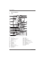
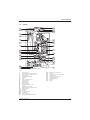
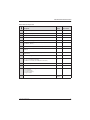
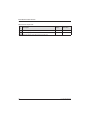
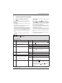
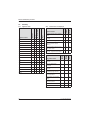
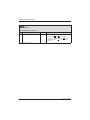
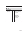
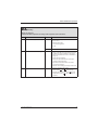
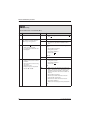
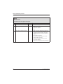
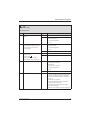
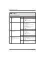
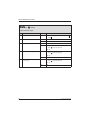
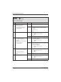
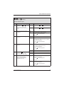
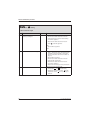
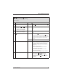
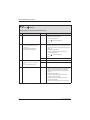
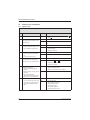
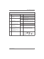
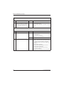
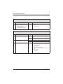
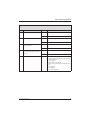
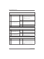
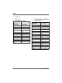
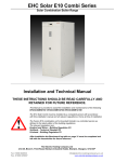
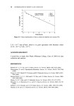
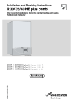
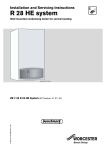
Service booklet for the Engineer
for Gas Condensing Boilers
6 720 610 577-00.10
7 181 465 346 GB (03.02) OSW
ZWB 7-29 CC1 GC-Number: 47 108 05
ZB 7-28 CS1 GC-Number: 41 108 02
ZWB 7-27 HE combi GC-Number: 47 311 55
ZWB 7-25 HE combi GC-Number: 47 311 73
ZWB 7-30 HE combi GC-Number: 47 311 74
ZB 7-27 HE system GC-Number: 41 311 49
ZB 7-28 HE system GC-Number: 41 311 58
Greenstar 29 HE Conventional GC-Number: Natural Gas: 41 311 56; LPG: 41 311 57
Table of contents
Table of contents
Warnings
3
Symbols
3
1
1.1
1.2
Layout of Appliance
combi
system
4
4
5
2
2.1
2.2
2.3
2.4
2.5
2.5.1
2.5.2
Bosch Heatronic board functions
Initialisation
Temperature display
Indication of faults
Special programme visualisation
Boiler service functions
First Service Level
Secondary Service Level
6
6
6
6
6
8
8
11
3
3.1
3.2
3.2.1
3.2.2
3.3
3.4
3.4.1
3.4.2
Failure identification procedure
Notes on using the fault code tables
Summary
Appliance faults
Faults that are not displayed
Error codes on the display
Faults that are not displayed
Appliance faults
Programmer faults
13
13
14
14
14
15
42
42
48
4
4.1
4.1.1
4.1.2
Appendix
NTC values
Outside temperature sensor
CH flow NTC sensor, heat store
NTC sensor, constant hot water
NTC sensor and hot water NTC sensor
4.2 Electronic schemes
4.3 List of most important replacement parts
4.4 Approved corrosion inhibitors and
anti-freeze fluids for central
heating water
4.4.1 Frost protection
4.4.2 Sealing agents
4.5 Summary of BDH Information Sheet
on Identifying Corrosion by CFCs
2
52
52
52
52
53
54
55
55
55
55
7 181 465 346 GB (03.02)
Warnings
Warnings
Repairs
B Repairs may only be carried out by an approved
installer!
B Before carrying out any work on the appliance,
switch it off at the master switch!
B Even when the appliance is switched off at the master switch, some components on the PCB control
board inside the control box are still live. Therefore:
B Before carrying out any work on the electrical parts
of the appliance fully disconnect it from the power
supply (e. g. by means of fuse or circuit breaker)!
B Flue ducting must not be modified in any way.
B Use only original spare parts!
Instructions to the customer
B Explain to the customer how the appliance works
and how to operate it.
B Advise the customer that he/she must not make any
modifications to the appliance or carry out any
repairs on it.
7 181 465 346 GB (03.02)
Symbols
Safety instructions in this document
are identified by a warning-triangle symbol and are printed on a grey background.
Signal words indicate the seriousness of the hazard in
terms of the consequences of not following the safety
instructions.
• Caution indicates that minor damage to property
could result.
• Warning indicates that minor personal injury or serious damage to property could result.
• Danger indicates that serious personal injury could
result. In particularly serious cases, lives could be at
risk.
i
Notes are identified by the symbol shown
on the left. They are bordered by horizontal
lines above and below the text.
Notes contain important information in cases where
there is no risk of personal injury or damage to property.
3
Layout of Appliance
1
Layout of Appliance
1.1
combi
120
221.1
349
221.2
234.1
234
27
226
20
102
32.1
29
36
271
6
415
43
9
63
416
358
18
64
423
7
18.1
355
418
6.1
15
8.1
88
295
98
417
4
6 720 610 576-02.2O
Fig. 1
4
6
6.1
7
8.1
9
15
18
18.1
20
27
29
32.1
36
43
63
64
88
98
102
4
Heatronic control
Heat exchanger safety temperature limiter
Hot water NTC sensor
Testing point for gas supply pressure
Pressure gauge
Flue gas temperature limiter
Relief valve
Pump
Pump speed selector switch
Expansion vessel
Automatic air vent
Air gas Mixer unit
Electrode assembly
Temperature sensor in CH flow
CH flow
Adjustable gas flow restrictor
Adjusting screw for min. gas flow volume
3-way valve (combi)
DHW flow switch (combi)
Inspection window
120
221.1
221.2
226
295
234
234.1
271
349
355
358
415
416
417
418
423
Fixing points
Flue duct
Combustion air intake
Fan assembly
Appliance type sticker
Testing point for combustion products
Testing point for combustion air
Flue duct
Cover plate for twin flue duct connection
Plate-type domestic hot water heat exchanger
Condensate trap
Cover plate for cleaning access
Condensate collector
Clip for fixing outer case
Data plate
Siphon
7 181 465 346 GB (03.02)
Layout of Appliance
1.2
system
120
221.1
349
221.2
234.1
234
27
226
20
102
32.1
29
36
271
6
415
43
9
63
416
358
18
64
423
7
18.1
418
15
8.1
295
4
417
6 720 610 596-01.2O
Fig. 2
4
6
7
8.1
9
15
18
18.1
20
27
29
32.1
36
43
63
64
102
120
221.1
221.2
226
295
234
Heatronic control
Heat exchanger safety temperature limiter
Testing point for gas supply pressure
Pressure gauge
Flue gas temperature limiter
Relief valve
Pump
Pump speed selector switch
Expansion vessel
Automatic air vent
Air gas Mixer unit
Electrode assembly
Temperature sensor in CH flow
CH flow
Adjustable gas flow restrictor
Adjusting screw for min. gas flow volume
Inspection window
Fixing points
Flue duct
Combustion air intake
Fan assembly
Appliance type sticker
Testing point for combustion products
7 181 465 346 GB (03.02)
234.1
271
349
358
415
416
417
418
423
Testing point for combustion air
Flue duct
Cover plate for twin flue duct connection
Condensate trap
Cover plate for cleaning access
Condensate collector
Clip for fixing outer case
Data plate
Siphon
5
Bosch Heatronic board functions
2
Bosch Heatronic board functions
2.1
Initialisation
When it is switched on, the appliance performs a selftest which takes about 5 seconds. While the test is in
progress, the display shows the following sequence of
codes:
P1 -> P2 -> P3 -> P4 -> P5 -> P6
On completion of the test sequence the appliance is
ready for operation.
2.2
Temperature display
2.4
Special programme visualisation
The display shows for example 45 – – 45 (continuous working at the minimum sanitary/heating
power)
The display shows alternatively the temperature
and – –. The function is memorised in the Service mode.
• The appliance works continuously at the sanitary or
heating minimum power.
B Press the button
until the symbol – – appears on
the display.
The button
is lighted.
B Turn the temperature control
until function 2.0
appears on the display.
After a short delay, the display shows 1 for minimum
output.
B Turn the temperature control
completely anticlockwise until the display shows 0 .
B Press the button
until the symbol [ ] appears on
the display.
The display shows the heating outlet temperature.
The display shows the current flow temperature in central heating and hot water modes. The display range
extends from 00 ˚C to 99 ˚C.
If a service function requires the display of a temperature greater than 99 ˚C, the display alternates between
initially showing the first digit and then the remaining
two digits.
E.g.: display showing 1. followed by 69. indicates
169˚C.
For outside temperatures, the display shows a minus
sign followed by the negative temperature in alternation.
The display shows for example 55 – – 55
(continuous working at the maximum power)
The display shows alternatively the temperature and – –.
The function is memorised in the Service mode.
2.3
• The appliance works continuously at the maximum
power.
Indication of faults
Faults are indicated by a letter code. This helps to identify and eliminate the cause of the fault quickly and reliably.
The fault codes displayed are grouped into four categories:
• Category 1:
The appliance is disabled until it has been switched
off and then on again.
• Category 2:
The appliance is disabled until the cause of the fault
has been eliminated.
• Category 3:
The appliance continues to operate with limited function.
• Category 4:
The appliance is disabled and locked (
flashes)
until the cause of the fault has been eliminated and
the appliance unlocked.
i
6
Unlocking the appliance:
B Press and hold the
display shows – – .
button until the
B Press the button
until the symbol – – appears on
the display.
The button
is lighted.
B Turn the temperature control
until function 2.0
appears on the display.
After about 5 seconds the display will show 2 for the
maximum power.
B Turn the temperature control
completely anticlockwise until the display shows 0 .
B Press the button
until the symbol [ ] appears on
the display.
The display shows the heating outlet temperature.
Display shows 45 -II- 45 (trap filling programme)
The trap filling programme ensures that the condensation trap is filled after the appliance is first installed or if
it has been switched off for a long period.
The trap filling programme is activated if:
• the appliance is switched on at the master switch
• the burner has not been in operation for at least 48
hours
• the appliance is switched from summer to winter
mode.
7 181 465 346 GB (03.02)
Bosch Heatronic board functions
The next time the central heating or heat store calls for
heat, the appliance is held at a low heat output for 15
minutes. The display shows -II- in alternation with the
CH flow temperature.The factory setting is 1 (enabled).
If the condensation trap is not filled with
water, flue gas can escape!
B The trap filling programme should only
be disabled in order to carry out servicing work.
B Always re-enable the trap filling programme after completing servicing
work.
To switch off the trap filling programme to carry out
servicing work:
B Press and hold the
and
buttons simultaneously until the display shows = =.
The
and
buttons will light up.
B Turn the temperature control
until the display
shows 8.5.
After a short delay, the display then shows the trap
filling programme setting ( 1. = Enabled).
B Turn the temperature control
until the display
shows 0. (= Disabled).
The display and the
and
buttons will flash.
B Press and hold the
and
buttons simultaneously until the display shows [ ].
The trap filling programme is now disabled.
B Regulate the temperature control
and the temperature control
on the previously set positions.
The display shows the heating outlet temperature.
Display shows 00 (venting function)
The first time the appliance is switched on, it automatically activates a one-off venting sequence in which the
heating pump switches on and off at intervals for about
8 minutes.
This function can be activated on Service Level 2, Service Code 7.3, if it is required at any other time.
7 181 465 346 GB (03.02)
7
Bosch Heatronic board functions
2.5
Boiler service functions
2.5.1
First Service Level
Operating
In order to change or check the values of the service
functions:
B Press the button
until the symbol – – appears on
the display.
The button
is lighted.
B Turn the temperature control
until the desired
function number appears on the display.
Once changed or checked the function value:
B Press the button
until the symbol [ ] appears on
the display.
The display shows the heating outlet temperature.
B Regulate the temperature control
and the temperature control
on the previously set positions.
In order to reset the main menu function values to their
default values:
B Power OFF the appliance.
B Press the button
and keep it pressed.
B Switch on the appliance, press and hold the
ton until the
display shows r1 followed by [ ].
but-
Values that can be modified:
Description
Display
Reset Value
.0
Show the last error code.
0 - FF
Clear only
2.0
Identification of the function mode (0 = normal, 1= min, 2 = max)
0-2
0
2.2
Identification of the pump function mode
1-3
2
2.3
Max. output in heat store heating mode
28 - 99
99
2.4
Anti-cycle time1)
0 - 15 min
3 min
2.5
Max. CH flow temperature
35 - 88˚C
88˚C
2.6
Minimum hysteresis in heating mode (∆T)
0 - 30 K
0K
2.7
Activation of automatic anti-cycle time (0 = Disabled; 1 = Enabled)
0, 1
1
3.4
Pump mode
0-3
2)
Table 1 First Service Level; Values that can be modified
1)
2)
8
If appliance is used in conjunction with type TA... programmer, only effective if Service Code 2.7 is set to “0” (= "Disabled”)!
The reset value is dependent on the code plug.
7 181 465 346 GB (03.02)
Bosch Heatronic board functions
Values that can only be read:
Description
Display
Reset Value
.1
Heating outlet temperature.
0 - 99˚C
-
.2
Sanitary outlet temperature.
0 - 99˚C
-
.3
Heat store NTC sensor (ZSB.)
0 - 99˚C
.4
Constant hot water NTC sensor (ZWB.)
0 - 99˚C
-
1.2
Order no. for code plug: 8 714 411 XXX
0 - 255
-
1.4
Temperature voltage signal (Terminal 2) from room thermostat
(eg. TRQ 21, TR 100)
5 - 22 VDC
-
1.5
Specified CH flow temperature from programmer
0 - 99˚C
-
1.6
Outside temperature from TA 211 E or room temperature from
TR 212 E
-20 +30˚C
-
1.7
Status TR 2 (0 = Not present 1 = Frost protection 3 = Auto 4 = Day,
Night 5=Error)
0-4
-
1.8
Terminal 2 on programmer interface module
0 - 24 VDC
-
1.9
Identification code for the external module:
0, 2, 4, 5 = no module connected,
3 = ADM, 6 = TA 211E, 53 = ADM, 56 = TR 212 E).
0 - 8, 53,
56
-
2.9
Instantaneous power.
0 - 99 %
-
3.0
Fan speed
0 - 105
-
3.3
Quality of the ionisation signal:
0 = no ionisation,
1 = weak ionisation,
2 = medium ionisation,
3 = high ionisation.
0-3
-
3.6
Software version
3x2
positions
-
Table 2 First Service Level; Values that can only be read
7 181 465 346 GB (03.02)
9
Bosch Heatronic board functions
Values that can only be read - only left display digit:
Description
Display XY
Reset Value
3.9
External switch (points 8 - 9).
0 = closed
1 = Heating demand
-
4.1
External demand for heat via LSM
0 = closed
1 = Heating demand
-
4.2
Programmable clock:
1st channel (Heating).
0 = closed
1 = Heating demand
-
4.3
Automatic pump shut OFF with RAM module
(point 5)
0 = closed
1 = Heating demand
-
4.4
Heating demand.
0 = closed
1 = Heating demand
-
4.5
Sanitary demand.
0 = closed
1 = Heating demand
-
Table 3 First Service Level; Values that can only be read - only left display digit
Values that can only be read - only right display digit:
Description
Display XY
Reset Value
3.9
External 2-point demand for heat via 230 V AC
(Terminals Ls - Lr)
0 = closed
1 = Heating demand
-
4.0
Heat store demand for heat via
heat store thermostat (Terminals 7-9)
0 = closed
1 = Heating demand
-
4.1
LSM Enable
0 = closed
1 = Heating demand
-
4.2
Programmable clock:
2nd channel (DHW – Maintaining).
0 = closed
1 = Heating demand
-
4.3
Heating demand from TA 211 E
0 = closed
1 = Heating demand
-
4.4
Heat store demand for heat via heat store NTC
sensor
0 = closed
1 = Heating demand
-
4.5
Sanitary heat exchanger temperature maintaining.
0 = closed
1 = Heating demand
-
4.6
Anti-cycle time
0 = closed
1 = Heating demand
-
Table 4 First Service Level; Values that can only be read - only right display digit
10
7 181 465 346 GB (03.02)
Bosch Heatronic board functions
2.5.2
Secondary Service Level
Operation
In order to change or check the values of the service
functions:
B Press buttons
and
simultaneously until the
symbol = = appears on the display.
The buttons
and
are lighted.
B Turn the temperature control
until the desired
function number appears on the display.
Once changed or checked the function value:
B Press buttons
and
simultaneously until the
symbol [ ] appears on the display.
The display shows the heating outlet temperature.
B Regulate the temperature control
and the temperature control
on the previously set positions.
To reset all settings on Service Levels 1 and 2 to the
factory setting:
B Power OFF the appliance.
B Press buttons
and
simultaneously and keep
them pressed.
B Switch on appliance, press and hold the
and
buttons until the display shows r2 followed by [ ].
Values that can be modified:
Description
Display
Reset Value
5.0
Reduced max. heating output
0 - 99 % and sealed
99
5.1
Continuous ignition (for testing ignition without
gas)
0 = off
1 = on
0
5.5
Increased min. heating and heat store charging
output
0 - 99 %
0
5.9
Starting speed option (if flame propagation is
poor, set high starting speed)
0 = First start at low speed;
1 = First start at high speed)
0
6.7
Pump deactivation in HW mode, ZW only.
0 = off, 1 = on
1
6.8
Cycle time for heat exchanger constant hot water
function on ZW model.
0 - 60 min
0
6.9
Constant hot water
0 - 30 min
3
7.3
Venting function
0 = off,
1 = On for 8 cycles then
permanently off (i.e. set to 0)
2 = on
1
7.7
Temperature-dependent output reduction
0 = off;
1 = Heating on
2 = Hot water on
3 = Heating and hot water on
3
8.5
Trap filling programme
0 = off
1 = on
1
Table 5 Secondary Service Level; Values that can be modified
7 181 465 346 GB (03.02)
11
Bosch Heatronic board functions
Values that can only be read:
Description
Display
Reset Value
5.2
Automatic gas igniter status and/or fault
00 - FF
-
9.3
Automatic gas igniter Asic fault code
00 - FF
-
Table 6 Secondary Service Level; Values that can only be read
12
7 181 465 346 GB (03.02)
Failure identification procedure
3
Failure identification procedure
3.1
Notes on using the fault code
tables
In this example: check the flue is clear by testing
the CO2 level.
The procedure is best described with the aid of
an example:
• Work through the table from top to bottom and from
left to right.
• First make a note of the present settings and restore
them before leaving the appliance.
• Read question 1. (Check column)and depending on
the answer (yes or no) read the action required from
the relevant box and carry out the instruction given;
ignore the other answer. For example: if the burner
flame is visible, follow the instructions for yes, i.e.
↓5.!
• ↓5. means go to number 5., ignoring the steps in
between.
EA
and
• If the appliance is locked (
button is flashing),
press the
button. Important: after unlocking the
appliance, always restart it (i.e. switch off and then
on again). Only then is it possible to say whether or
not the fault has been eliminated.
• If the fault has been rectified, the appliance will then
start up without indicating a fault and the fault isolation procedure is complete.
• If the fault is still present after performing the action
specified and, if necessary, restarting the appliance,
move on to the next step in the fault isolation procedure.
• If another fault code is displayed, work through the
fault code table for that code.
flashing.
Flame not detected
Check
Action
B Note the setting of the temperature controls
and
1.
2.
Is a burner flame visible?
Is the gas cock turned on?
.
yes:
↓ 5.
no:
↓ 2.
yes:
↓ 5.
no:
B Open the gas cock.
B Press
, restart the appliance.
EA? ↓3.
3.
Has the thermal cut-out on the gas
cock tripped?
4. ...
...
5. ...
Problem with flue?
B Check CO2 level in combustion
air.
Is CO2 level above 0,2 % ?
yes:
...
no:
↓ ...
yes:
Check flue.
no:
↓ ...
Return to normal operation:
B Press the button
on the display.
until the symbol [ ] appears
B Regulate the temperature control
and the
temperature control
on the previously set
positions.
Table 7
7 181 465 346 GB (03.02)
13
Failure identification procedure
ZWB ...A
Page
X
X
42
Flue gas levels incorrect, CO level
too high
X
X
43
3
X
17
Ignition too harsh, ignition poor.
X
X
44
A8
3
X
X
X
19
Boiler indicates P1, P2, P3 at
start-up and then restarts
with P1,...
X
X
46
AC
3
X
X
X
20
Ad
3
X
b1
2
X
X
X
24
C1
2
X
X
X
25
CC
3
X
X
X
26
d3
2
X
X
X
27
E2
2
X
X
X
28
E9
4
X
X
X
30
EA
4
X
X
X
32
F0
4/
2
X
X
X
F7
4
X
X
FA
4
X
Fd
4
X
22
Loose or broken contact on heat
store NTC sensor
X
X
46
Specified CH flow temperature
from TA... programmer exceeded
X
X
47
Table 9
Programmer faults
Page
A7
TA 211E
and DT 2
15
TR 2 and
TR 212 E
X
ZB ...A
3
Table 8
Excessive burner noise, rumbling
noises
Appliance faults
A5
Appliance faults
Faults that are not displayed
ZB ...A
3.2.2
Page
Appliance faults
ZWB ...A
3.2.1
ZB ...A Conventional
Summary
Category
3.2
Set room temperature not
reached.
X
48
37
Set room temperature
exceeded.
X
X
38
X
49
X
X
39
Set room temperature not
reached.
X
X
41
Set room temperature
exceeded by large amount.
X
50
Excessive fluctuations in
room temperature
X
X
50
Temperature rises instead of
falling
X
X
51
Room temperature too high
in Economy mode
X
X
50
Incorrect or no modulation
X
X
51
Heat store fails to heat up
X
Table 10
14
7 181 465 346 GB (03.02)
Failure identification procedure
3.3
Error codes on the display
A5
flashing.
Heat store NTC sensor 2 defective
Check
Action
B Note the setting of the temperature controls
and
1.
B Press button
.
yes:
B Select service function .3 .
Is a temperature between 0. and
5. displayed?
2.
Heat store NTC:
B Unplug connector.
B Short circuit the connector.
Display changes to temperature
between 99. and 95.
.
B Flue gas connector corroded 1), damaged or
dirty?. Change relative parts.
↓2.
no:
↓3.
yes:
B
B
B
B
Power OFF the appliance.
Change NTC sensor.
Plug the connection wire.
Turn ON the appliance.
A5? ↓3.
no:
B Change the 20-pin connector lead assembly.
↓3.
3.
4.
Temperature between 95. and 99. is
displayed.
B Unplug connector.
After max. 60 sec.:
Does the displayed code change
to a value between 0. and 5.?
B Unplug 20-pin connector from
PCB.
After max. 60 sec.:
Does the displayed code change
to a value between 0. and 5.?
yes:
B
B
B
B
Power OFF the appliance.
Change NTC sensor.
Plug the connection wire.
Turn ON the appliance.
A5? ↓4.
no:
↓4.
yes:
B
B
B
B
B
Power OFF the appliance.
Disconnect the boiler electrical connection.
Change the 20-pin connector lead assembly.
Reconnect the boiler electrical connection.
Turn ON the appliance.
↓5.
no:
7 181 465 346 GB (03.02)
B Make a note of the altered service settings (see
table 1, "First Service Level; Values that can be
modified" at page 8 and table 5, "Secondary
Service Level; Values that can be modified" at
page 11).
B Power OFF the appliance.
B Disconnect the boiler electrical connection.
B Change PCB control board.
B Reconnect the boiler electrical connection.
B Turn ON the appliance.
B Restore service settings previously noted down.
15
Failure identification procedure
A5
flashing.
Heat store NTC sensor 2 defective
Check
5.
Action
To return to normal function mode:
B Press buttons
and
simultaneously.
B Regulate the temperature control
and the
temperature control
on the previously set
positions.
1)
16
For notes, refer to Appendix
7 181 465 346 GB (03.02)
Failure identification procedure
A7
flashing.
Hot water NTC sensor defective
Check
Action
B Note the setting of the temperature controls
and
1.
B Press button
.
yes:
B Select service function .2 .
Is a temperature between 0. and
5. displayed?
2.
Hot water NTC sensor:
B Unplug connector.
B Short circuit the connector.
Display changes to
temperature 99.
.
B Flue gas connector corroded 1), damaged or
dirty? Change relative parts.
↓2.
no:
↓3.
yes:
B
B
B
B
B
B
B
Power OFF the appliance.
Drain the hot water circuit.
Disconnect the boiler electrical connection.
Change NTC sensor.
Plug the connection wire.
Reconnect the boiler electrical connection.
Turn ON the appliance.
A7? ↓3.
no:
B Change the 20-pin connector lead assembly.
↓3.
3.
Temperature between 95. and 99. is
displayed.
B Unplug connector.
After max. 60 sec.:
Does the displayed code change
to a value between 0. and 5.?
yes:
B
B
B
B
B
B
B
B
Power OFF the appliance.
Disconnect the boiler electrical connection.
Change NTC sensor.
Refill the hot water circuit.
Check the built-in NTC sensor for leaks.
Plug the connection wire.
Reconnect the boiler electrical connection.
Turn ON the appliance.
A7? ↓4.
no:
7 181 465 346 GB (03.02)
↓4.
17
Failure identification procedure
A7
flashing.
Hot water NTC sensor defective
Check
4.
B Unplug 20-pin connector from
PCB.
After max. 60 sec.:
Does the displayed code change
to a value between 0. and 5.?
Action
yes:
B
B
B
B
B
Power OFF the appliance.
Disconnect the boiler electrical connection.
Change the 20-pin connector lead assembly.
Reconnect the boiler electrical connection.
Turn ON the appliance.
↓5.
no:
B Make a note of the altered service settings (see
table 1, "First Service Level; Values that can be
modified" at page 8 and table 5, "Secondary
Service Level; Values that can be modified" at
page 11).
B Power OFF the appliance.
B Disconnect the boiler electrical connection.
B Change PCB control board.
B Reconnect the boiler electrical connection.
B Turn ON the appliance.
B Restore service settings previously noted down.
↓5.
5.
To return to normal function mode:
B Press buttons
and
simultaneously.
B Regulate the temperature control
and the
temperature control
on the previously set
positions.
1)
18
For notes, refer to Appendix
7 181 465 346 GB (03.02)
Failure identification procedure
A8
flashing.
No correct electrical connection
Check
1.
TR 2 connected?
Action
yes:
A8? ↓2.
no:
B Power OFF the appliance.
B Connect TR 2.
B Turn ON the appliance.
A8? ↓2.
2.
3.
B Turn switch until it clicks into position.
Mode selector switch is between two
settings
A8? ↓3.
B Power OFF the appliance.
Wiring between TR 2 and TR 212 E
OK?
yes:
• Terminal 3 on TR 2 connected to
Terminal 3 on TR 212 E?
no:
• Terminal 4... Terminal 4....
B Turn ON the appliance.
↓4.
B Rewire correctly as specified in the installation
instructions.
B Turn ON the appliance.
After 90 sec.:
A8? ↓4.
4.
TR 2 defective
7 181 465 346 GB (03.02)
B Power OFF the appliance.
B Change TR 2.
B Turn ON the appliance.
19
Failure identification procedure
AC
flashing.
Module not detected.
(Constant CH flow temperature according to CH temperature control on boiler.)
Check
Action
B Note the setting of the temperature controls
and
1.
B Press button
.
yes:
B Select service function 1.9 .
Code 0., 2., 4., 5. is displayed.
.
No modul detected.
B Disconnect connecting lead between PCB control board and TA 211 E or TA 212 E.
B Re-connect connecting lead.
AC? ↓3.
2.
3.
Are 24 V DC cables routed alongside 230 V AC cables?
no:
↓2.
yes:
B Ensure cable separation conforms to minimum
requirements as per installation instructions and/
or use shielded cable.
no:
↓3.
B Power OFF the appliance.
B Replace connecting lead between PCB control
board and programmer interface module or TA
211 E.
B Turn ON the appliance.
Connecting lead between PCB control board and TA 211 E or TA 212 E
defective.
AC? ↓4.
4.
5.
TA 211 E connected?
B Select service function 1.6 .
Outside temperature between -20
and +30 ˚C is displayed.
Does temperature displayed
match true outside temperature?
yes:
↓5.
no:
↓8.
yes:
↓7.
no:
B Power OFF the appliance.
B Replace outside temperature sensor.
B Turn ON the appliance.
AC? ↓7.
6.
If remote control installed:
B Select service function 1.7 .
Remote control status 0. is displayed .
yes:
AC? ↓7.
no:
20
B Power OFF the appliance.
B Plug the connection wire.
B Turn ON the appliance.
↓7.
7 181 465 346 GB (03.02)
Failure identification procedure
AC
flashing.
Module not detected.
(Constant CH flow temperature according to CH temperature control on boiler.)
Check
7.
Remote control status still 0.?
Action
yes:
B Power OFF the appliance.
Remote control:
B Replace top section.
B Turn ON the appliance.
AC? ↓8.
no:
8.
The PCB control board is damaged.
↓8.
B Make a note of the altered service settings (see
table 1, "First Service Level; Values that can be
modified" at page 8 and table 5, "Secondary
Service Level; Values that can be modified" at
page 11).
B Power OFF the appliance.
B Disconnect the boiler electrical connection.
B Change PCB control board.
B Reconnect the boiler electrical connection.
B Turn ON the appliance.
B Restore service settings previously noted down.
To return to normal function mode:
B Press buttons
and
simultaneously.
B Regulate the temperature control
and the
temperature control
on the previously set
positions.
7 181 465 346 GB (03.02)
21
Failure identification procedure
Ad
flashing.
Heat store NTC sensor 1 not detected (ZB...).
Check
Action
B Note the setting of the temperature controls
and
1.
2.
.
Is connecting lead for heat store
NTC sensor 1 correctly routed, i.e.
not through cable grommet?
yes:
↓2.
no:
B Route connecting lead for heat store temperature sensor as specified in installation instructions.
B Press button
yes:
Is NTC sensor connector corroded, damaged or
dirty?
B Power OFF the appliance.
B Change NTC sensor.
B Turn ON the appliance.
.
B Select service function .3 .
Is a temperature between 0. and
5. displayed?
B Press button
.
Ad? ↓3.
3.
Heat store -NTC 1:
B Unplug connector from PCB control board.
B Short circuit the connector using
wire jumper.
After max. 60 sec:
Display changes to temperature
between 99. and 95.
no:
↓4.
yes:
B Power OFF the appliance.
B Change NTC sensor.
B Turn ON the appliance.
B Press button
.
↓4.
no:
B Make a note of the altered service settings (see
table 1, "First Service Level; Values that can be
modified" at page 8 and table 5, "Secondary
Service Level; Values that can be modified" at
page 11).
B Power OFF the appliance.
B Disconnect the boiler electrical connection.
B Change PCB control board.
B Reconnect the boiler electrical connection.
B Turn ON the appliance.
B Restore service settings previously noted down.
↓4.
22
7 181 465 346 GB (03.02)
Failure identification procedure
Ad
flashing.
Heat store NTC sensor 1 not detected (ZB...).
Check
4.
Temperature between 99. and 95. is
displayed.
B Unplug connector.
After max. 60 sec.:
Does the displayed code change
to a value between 0. and 5.?
Action
yes:
B Power OFF the appliance.
B Change NTC sensor.
B Turn ON the appliance.
no:
B Make a note of the altered service settings (see
table 1, "First Service Level; Values that can be
modified" at page 8 and table 5, "Secondary
Service Level; Values that can be modified" at
page 11).
B Power OFF the appliance.
B Disconnect the boiler electrical connection.
B Change PCB control board.
B Reconnect the boiler electrical connection.
B Turn ON the appliance.
B Restore service settings previously noted down.
To return to normal function mode:
B Press buttons
and
simultaneously.
B Regulate the temperature control
and the
temperature control
on the previously set
positions.
7 181 465 346 GB (03.02)
23
Failure identification procedure
b1
flashing.
The Heatronic does not recognise the code key.
Check
B Power OFF the appliance.
1.
2.
Action
Code plug loose, incorrect or defective.
B Replace code plug, check code number is correct.
B Turn ON the appliance.
b1? ↓3.
3.
24
The PCB control board is damaged.
B Make a note of the altered service settings (see
table 1, "First Service Level; Values that can be
modified" at page 8 and table 5, "Secondary
Service Level; Values that can be modified" at
page 11).
B Power OFF the appliance.
B Disconnect the boiler electrical connection.
B Change PCB control board.
B Reconnect the boiler electrical connection.
B Turn ON the appliance.
B Restore service settings previously noted down.
7 181 465 346 GB (03.02)
Failure identification procedure
C1
flashing.
Fan speed too low
Check
1.
Action
Fan lead connector properly connected?
yes:
↓2.
no:
B Power OFF the appliance.
B Plug in connector.
B Turn ON the appliance.
C1? ↓2.
2.
3.
Is fan lead defective?
B Is impedance reading between the
two connectors for one of the
cores infinity?
Are the differential pressure switch
contacts closed?
B Press button
.
yes:
B Power OFF the appliance.
B Replace fan lead.
B Turn ON the appliance.
C1? ↓3.
no:
↓3.
yes:
↓4.
no:
↓4.
yes:
B
B
B
B
B
B Select service function 3.8 .
Is left digit of display showing 1?
4.
Fan defective?
Power OFF the appliance.
Plug the connection wire.
Replace fan.
Plug the connection wire.
Turn ON the appliance.
C1? ↓5.
no:
5.
The PCB control board is damaged.
7 181 465 346 GB (03.02)
↓5.
B Make a note of the altered service settings (see
table 1, "First Service Level; Values that can be
modified" at page 8 and table 5, "Secondary
Service Level; Values that can be modified" at
page 11).
B Power OFF the appliance.
B Disconnect the boiler electrical connection.
B Change PCB control board.
B Reconnect the boiler electrical connection.
B Turn ON the appliance.
B Restore service settings previously noted down.
25
Failure identification procedure
CC
flashing.
Outside temperature NTC sensor not detected.
(Boiler heating as if outside temperature is -20˚C)
Check
1.
Outside temperature sensor AF2
connected to Terminals A and F on
TA 211 E?
Action
yes:
↓2.
no:
B Power OFF the appliance.
B Connect outside temperature sensor to Terminals A and F on TA 211 E.
B Turn ON the appliance.
CC? ↓2.
2.
26
B Power OFF the appliance.
B Disconnect outside temperature
sensor and test resistance
R = ∞ or R = 0?
B Change the external sensor.
B Turn ON the appliance.
7 181 465 346 GB (03.02)
Failure identification procedure
d3
flashing.
Wrong signal from pin 8-9 (open?).
Check
1.
2.
Action
B Turn ON the appliance.
B Measure voltage between Terminal 4 and Terminal 8.
Voltage ≅ 24 V DC?
yes:
↓2.
no:
↓3.
Existing heat store thermostat connected to Terminals 7, 8 and 9?
yes:
B Power OFF the appliance.
B Fix the additional bridge 8-9 in the right position
and close the screws.
B Turn ON the appliance.
d3? ↓3.
3.
Break in connecting lead?
no:
↓4.
yes:
B Power OFF the appliance.
B Plug the connection wire.
B Turn ON the appliance.
d3? ↓4.
no:
4.
The PCB control board is damaged.
7 181 465 346 GB (03.02)
↓4.
B Make a note of the altered service settings (see
table 1, "First Service Level; Values that can be
modified" at page 8 and table 5, "Secondary
Service Level; Values that can be modified" at
page 11).
B Power OFF the appliance.
B Disconnect the boiler electrical connection.
B Change PCB control board.
B Reconnect the boiler electrical connection.
B Turn ON the appliance.
B Restore service settings previously noted down.
27
Failure identification procedure
E2
flashing.
The heating outlet NTC sensor is damaged.
Check
Action
B Note the setting of the temperature controls
and
1.
B Press button
.
yes:
B Select service function .1 .
Is a temperature between 0. and
5. displayed?
.
The heating outlet NTC sensor is in short circuit:
B Power OFF the appliance.
B Replace CH flow NTC sensor; observe fitting
instructions for NTC sensor when doing so.
B Turn ON the appliance.
E2? ↓2.
2.
Temperature for heating outlet NTC
sensor between 95. and 99. is displayed.
no:
↓2.
yes:
The CH flow NTC sensor is interrupted :
B Power OFF the appliance.
B Replace CH flow NTC sensor; observe fitting
instructions for NTC sensor when doing so.
B Turn ON the appliance.
E2? ↓3.
no:
3.
Check if the 20-pin connector lead
assembly is damaged.
↓3.
B
B
B
B
B
Power OFF the appliance.
Disconnect the boiler electrical connection.
Change the 20-pin connector lead assembly.
Reconnect the boiler electrical connection.
Turn ON the appliance.
E2? ↓4.
4.
28
The PCB control board is damaged.
B Make a note of the altered service settings (see
table 1, "First Service Level; Values that can be
modified" at page 8 and table 5, "Secondary
Service Level; Values that can be modified" at
page 11).
B Power OFF the appliance.
B Disconnect the boiler electrical connection.
B Change PCB control board.
B Reconnect the boiler electrical connection.
B Turn ON the appliance.
B Restore service settings previously noted down.
7 181 465 346 GB (03.02)
Failure identification procedure
E2
flashing.
The heating outlet NTC sensor is damaged.
Check
Action
To return to normal function mode:
B Press buttons
and
simultaneously.
B Regulate the temperature control
and the
temperature control
on the previously set
positions.
7 181 465 346 GB (03.02)
29
Failure identification procedure
E9
and
flashing.
Safety temperature limiter has tripped.
Check
1.
Is the heating pressure between 1
and 2 bar?
Action
yes:
↓2.
no:
B Top up system.
B Vent appliance.
B Press
, restart the appliance.
E9? ↓2.
2.
Is the pump blocked?
yes:
B Unblock the pump.
If pump won’t start:
B Power OFF the appliance.
B Disconnect the boiler electrical connection.
B Change the pump.
B Reconnect the boiler electrical connection.
B Turn ON the appliance.
B Press
, restart the appliance.
E9? ↓3.
3.
Lead disconnected from safety temperature limiters?
no:
↓3.
yes:
B Power OFF the appliance.
B Connect lead.
B Turn ON the appliance.
B Press
, restart the appliance.
E9? ↓4.
4.
B Power OFF the appliance.
B Unplug the connector from the
cut-off device.
B Measure the NTC electrical resistance.
no:
↓4.
yes:
B Change the over heating cut-off device.
B Connect flue gas safety temperature limiter lead.
B Turn ON the appliance.
B Press
, restart the appliance.
E9? ↓5.
R = ∞?
no:
B Connect flue gas safety temperature limiter lead.
B Turn ON the appliance.
↓5.
30
7 181 465 346 GB (03.02)
Failure identification procedure
E9
and
flashing.
Safety temperature limiter has tripped.
Check
5.
Is lead disconnected from CH flow
safety temp. limiter?
Action
yes:
B Power OFF the appliance.
B Reconnect lead.
B Turn ON the appliance.
B Press
, restart the appliance.
↓6.
6.
B Power OFF the appliance.
B Disconnect lead to CH flow safety
temperature limiter.
B Measure the CH flow safety temperature limiter.
R = ∞?
no:
↓6.
yes:
B Change CH flow safety temperature limiter.
B Connect CH flow safety temperature limiter lead.
B Turn ON the appliance.
B Press
, restart the appliance.
E9? ↓7.
no:
B Connect CH flow safety temperature limiter lead.
B Turn ON the appliance.
↓7.
7.
B Power OFF the appliance.
B Remove fuse SI 3 from appliance
PCB control board and test for
continuity.
R = ∞?
yes:
B Change the fuse.
B Turn ON the appliance.
B Press
, restart the appliance.
E9? ↓8.
no:
B Remount the fuse.
B Turn ON the appliance.
↓8.
8.
The PCB control board is damaged.
7 181 465 346 GB (03.02)
B Make a note of the altered service settings (see
table 1, "First Service Level; Values that can be
modified" at page 8 and table 5, "Secondary
Service Level; Values that can be modified" at
page 11).
B Power OFF the appliance.
B Disconnect the boiler electrical connection.
B Change PCB control board.
B Reconnect the boiler electrical connection.
B Turn ON the appliance.
B Restore service settings previously noted down.
31
Failure identification procedure
EA
and
flashing.
No flame ionisations signal
Check
Action
B Note the setting of the temperature controls
and
1.
2.
Is the flame present?
Is the gas cock open?
.
yes:
↓6.
no:
↓2.
yes:
↓3.
no:
B Open the gas cock.
B Press
, restart the appliance.
EA? ↓3.
3.
Is there air in the supply pipe?
yes:
B Vent supply pipe.
B Press
, restart the appliance.
EA? ↓4.
4.
Did the thermal security of the gas
cock lock out?
no:
↓4.
yes:
B Reset security.
B Press
, restart the appliance.
EA? ↓5.
no:
32
↓5.
7 181 465 346 GB (03.02)
Failure identification procedure
EA
and
flashing.
No flame ionisations signal
Check
5.
Natural gas models:
does the building have a supply pressure regulator?
Action
yes:
B Check that it is fitted correctly and functioning
properly and correct if necessary.
B Check supply pressure, inform gas company if
outside correct range.
B Is correct code plug fitted?
B Press
, restart the appliance.
EA? ↓6.
LPG models:
is the flow rate of the gas supply to
the appliance correct?
no:
↓6.
yes:
↓6.
no:
B Is there enough gas in the supply cylinder?
B Is there air in the supply pipe?
B Is the solenoid valve in the "meter cabinet” opening?
B Is the supply pressure OK? (if the supply pressure is too high, check the pressure regulator in
the “meter cabinet” and on the LPG supply cylinder).
B Press
, restart the appliance.
EA? ↓6.
6.
Is the ground connection correct?
yes:
↓7.
no:
B Correct the electrical ground connection.
B Press
, restart the appliance.
EA? ↓7.
7.
Two phase net:
Is there a resistor fitted between Pe
and N?
yes:
↓8.
no:
B Power OFF the appliance.
B Disconnect the boiler electrical connection.
B Insert a 2 MΩ resistance between the ground
and the N connection.
B Reconnect the boiler electrical connection.
B Turn ON the appliance.
B Press
, restart the appliance.
EA? ↓11.
7 181 465 346 GB (03.02)
33
Failure identification procedure
EA
and
flashing.
No flame ionisations signal
Check
8.
Is diaphragm in the mixer unit correctly fitted and functional?
B Open mixer unit (29).
B Check diaphragm for correct orientation, soiling and splitting.
Is diaphragm OK?
Action
yes:
B Close mixer unit.
↓9.
no:
B Insert diaphragm in the fan intake duct as per
installation instructions so that the flaps open
upwards.
B Close mixer unit.
EA? ↓9.
9.
Is the condensation trap blocked?
yes:
B Clean out condensation trap discharge pipe.
B Press
, restart the appliance.
EA? ↓13.
10.
Check the gas valve?
B Power OFF the appliance.
B Unplug the connectors from the
gas valve.
B Measure the gas valve coils I and
II electrical resistance.
R = 164 ± 40Ω ?
no:
↓10.
yes:
B Reconnect the gas valve.
B Turn ON the appliance.
B Press
, restart the appliance.
EA? ↓11.
no:
B Change the gas valve.
B Reconnect the gas valve.
B Turn ON the appliance.
B Press
, restart the appliance.
EA? ↓11.
11.
12.
Problem with flue?
B Check CO2 level in combustion
air.
Is CO2 level above 0,2 % ?
yes:
B Check flue and clean if necessary.
B Press
, restart the appliance.
EA? ↓12.
B Open up heat exchanger - is it
dirty?
no:
↓12.
Is flue gas CO2 level incorrect1)?
yes:
B Adjust to correct level.
B Press
, restart the appliance.
EA? ↓13.
no:
34
↓13.
7 181 465 346 GB (03.02)
Failure identification procedure
EA
and
flashing.
No flame ionisations signal
Check
13.
14.
Action
B Press buttons
and
simultaneously.
B Select service-function 5.1.
Continuous ignition (without gas)
OK?
yes:
Ignition lead connected to ignition
electrodes?
yes:
↓15.
no:
B Connect cable to ignition electrode.
B Press buttons
and
simultaneously.
and
simultaneously.
↓14.
no:
B Press buttons
↓17.
B Press
, restart the appliance.
EA? ↓15.
15.
Ignition cable connector engaged in
switchbox?
yes:
↓16.
no:
B Power OFF the appliance.
B Engage ignition cable connector in switchbox.
B Turn ON the appliance.
B Press
, restart the appliance.
EA? ↓16.
16.
Is the ignition electrical wire
damaged?
yes:
B Power OFF the appliance.
B Change the ignition electrical wire.
B Turn ON the appliance.
B Press
, restart the appliance.
EA? ↓17.
17.
18.
no:
↓17.
yes:
↓19.
B Select service-function 3.3.
Is the ionisation quality 2. or 3. ?
no:
↓18.
Electrode assembly defective?
B Power OFF the appliance.
B Remove electrode assembly.
Electrodes worn out?
yes:
B Replace electrode assembly.
B Turn ON the appliance.
B Press button
.
B Press
, restart the appliance.
EA? ↓19.
no:
B Refit electrode assembly.
B Turn ON the appliance.
B Press
, restart the appliance.
EA? ↓19.
7 181 465 346 GB (03.02)
35
Failure identification procedure
EA
and
flashing.
No flame ionisations signal
19.
Check
Action
Check if the 20-pin connector lead
assembly is damaged.
B
B
B
B
B
Power OFF the appliance.
Disconnect the boiler electrical connection.
Change the 20-pin connector lead assembly.
Turn ON the appliance.
Reconnect the boiler electrical connection.
B Press
, restart the appliance.
EA?
B Power OFF the appliance.
↓20.
20.
The PCB control board is damaged.
B Make a note of the altered service settings (see
table 1, "First Service Level; Values that can be
modified" at page 8 and table 5, "Secondary
Service Level; Values that can be modified" at
page 11).
B Power OFF the appliance.
B Disconnect the boiler electrical connection.
B Change PCB control board.
B Reconnect the boiler electrical connection.
B Turn ON the appliance.
B Restore service settings previously noted down.
To return to normal function mode:
B Press buttons
and
simultaneously.
B Regulate the temperature control
and the
temperature control
on the previously set
positions.
1)
36
See installation instructions
7 181 465 346 GB (03.02)
Failure identification procedure
F0
(and possibly
) flashing.
Internal failure
Check
Action
B Note the setting of the temperature controls
and
1.
2.
3.
.
B Press buttons
and
simultaneously.
B Select service function 9.3 .
A service code is displayed.
B Enter figure displayed in customer service record.
B Select service function 5.2 .
A service code is displayed.
B Enter figure displayed in customer service record.
flashing?
↓2.
↓3.
yes:
B Press button
.
B Initiate demand for heat by pressing
button
and then press again after 30 seconds to cancel.
B Initiate two more demands for heat as above.
F0? ↓4.
no:
4.
The PCB control board is damaged.
↓4.
B Make a note of the altered service settings (see
table 1, "First Service Level; Values that can be
modified" at page 8 and table 5, "Secondary
Service Level; Values that can be modified" at
page 11).
B Power OFF the appliance.
B Disconnect the boiler electrical connection.
B Change PCB control board.
B Reconnect the boiler electrical connection.
B Turn ON the appliance.
B Restore service settings previously noted down.
To return to normal function mode:
B Press buttons
and
simultaneously.
B Regulate the temperature control
and the
temperature control
on the previously set
positions.
7 181 465 346 GB (03.02)
37
Failure identification procedure
F7
and
flashing.
Although appliance switches off, flame still detected
1.
Check
Action
Electrode(s) dirty or defective.
B Power OFF the appliance.
B Replace electrode assembly.
B Turn ON the appliance.
B Press
, restart the appliance.
F7? ↓2.
2.
B Power OFF the appliance.
B Disconnect the boiler electrical
connection.
B Remove PCB control board.
PCB control board damp?
yes:
B Dry PCB control board (e.g. with hair dryer).
B Look for point where damp is entering switchbox
and seal as necessary (cable grommets properly
fitted, ...?).
B Refit PCB control board.
B Reconnect the boiler electrical connection.
B Turn ON the appliance.
B Press
, restart the appliance.
F7? ↓3.
3.
4.
38
Problem with flue?
B Check CO2 level in combustion
air.
Is CO2 level above 0,2 % ?
The PCB control board is damaged.
no:
↓3.
yes:
B Check flue and repair or replace if necessary.
no:
↓4.
B Make a note of the altered service settings (see
table 1, "First Service Level; Values that can be
modified" at page 8 and table 5, "Secondary
Service Level; Values that can be modified" at
page 11).
B Power OFF the appliance.
B Disconnect the boiler electrical connection.
B Change PCB control board.
B Reconnect the boiler electrical connection.
B Turn ON the appliance.
B Restore service settings previously noted down.
7 181 465 346 GB (03.02)
Failure identification procedure
FA
and
flashing.
Although appliance switches off, flame still detected
Check
Action
B Note the setting of the temperature controls
and
.
B Power OFF the appliance.
1.
Condensation trap blocked?
yes:
B Clean condensation trap discharge pipe.
B Press
, restart the appliance.
FA? ↓2.
2.
Electrode assembly defective?
B Power OFF the appliance.
B Remove electrode assembly.
Electrode assembly burnt out?
no:
↓2.
yes:
B Replace electrode assembly.
B Turn ON the appliance.
B Press
, restart the appliance.
FA?
B Power OFF the appliance.
↓3.
no:
B Refit electrode assembly.
B Turn ON the appliance.
B Press
, restart the appliance.
FA? ↓3.
3.
Problem with flue?
B Check CO2 level in combustion
air.
Is CO2 level above 0,2 % ?
yes:
B Check flue and repair or replace if necessary.
B Press
, restart the appliance.
FA?
B Power OFF the appliance.
↓4.
no:
4.
The gas valve is damaged.
↓4.
B Change the gas valve.
B Turn ON the appliance.
B Press
, restart the appliance.
FA?
B Power OFF the appliance.
↓5.
7 181 465 346 GB (03.02)
39
Failure identification procedure
FA
and
flashing.
Although appliance switches off, flame still detected
5.
Check
Action
Check if the 20-pin connector lead
assembly is damaged.
B
B
B
B
B
Power OFF the appliance.
Disconnect the boiler electrical connection.
Change the 20-pin connector lead assembly.
Turn ON the appliance.
Reconnect the boiler electrical connection.
B Press
, restart the appliance.
FA?
B Power OFF the appliance.
↓6.
6.
40
The PCB control board is damaged.
B Make a note of the altered service settings (see
table 1, "First Service Level; Values that can be
modified" at page 8 and table 5, "Secondary
Service Level; Values that can be modified" at
page 11).
B Power OFF the appliance.
B Disconnect the boiler electrical connection.
B Change PCB control board.
B Reconnect the boiler electrical connection.
B Turn ON the appliance.
B Restore service settings previously noted down.
7 181 465 346 GB (03.02)
Failure identification procedure
Fd
Button
and
flashing.
pressed without necessity
Check
1.
Button
Action
is flashing.
B Press
, restart the appliance.
Fd? ↓2.
2.
The PCB control board is damaged.
7 181 465 346 GB (03.02)
B Make a note of the altered service settings (see
table 1, "First Service Level; Values that can be
modified" at page 8 and table 5, "Secondary
Service Level; Values that can be modified" at
page 11).
B Power OFF the appliance.
B Disconnect the boiler electrical connection.
B Change PCB control board.
B Reconnect the boiler electrical connection.
B Turn ON the appliance.
B Restore service settings previously noted down.
41
Failure identification procedure
3.4
Faults that are not displayed
3.4.1
Appliance faults
Excessive burner noise, rumbling noises
Check
Action
B Note the setting of the temperature controls
and
1.
Does the gas supply type match the
specifications on the appliance identification plate?
.
yes:
↓2.
no:
B Convert appliance to correct gas type.
↓2.
2.
3.
4.
B Test gas supply pressure - OK?
Does pressure match figure specified in installation instructions?
yes:
↓3.
no:
B Decommission appliance.
For natural gas:
B Notify gas company.
Problem with flue?
B Check CO2 level in combustion
air.
Is CO2 level above 0,2 % ?
yes:
B Check flue and repair or replace if necessary.
no:
↓3.
Cascade system:
Is the appliance min. output high
enough to open the shut-off device?
yes:
↓5.
no:
B Press buttons
and
simultaneously.
B Select Service Function 5.5 .
B Increase min. output.
5.
6.
Is appliance’s internal air/flue channel leaking or blocked?
B Open up heat exchanger and
inspect.
B Remove silencer, flue duct and air
flow limit.
B Open trap and inspect.
Air channels dirty/clogged, seals
defective or not correctly fitted?
yes:
B Repair or replace components.
B Grease seal before fitting.
B Make sure it is fitted in correct position.
no:
↓6.
B Measure CO2 levels.
yes:
B Adjust CO2 level as per installation instructions.
no:
B
B
B
B
B
B
CO2 levels in flue gas at min and
max output do not match figures
specified in installation instructions.
42
Turn off gas cock.
Power OFF the appliance.
Change the gas valve.
Open the gas cock.
Turn ON the appliance.
Check appliance for leaks.
7 181 465 346 GB (03.02)
Failure identification procedure
Excessive burner noise, rumbling noises
7.
Check
Action
B Press buttons
and
simultaneously.
B Select service-function 5.9.
0 is displayed.
B Set to 1 for high start-up speed.
Flue gas levels incorrect, CO level too high
Check
1.
Does the gas supply type match the
specifications on the appliance identification plate?
Action
yes:
↓2.
no:
B Convert appliance to correct gas type.
↓2.
2.
3.
4.
5.
yes:
↓3.
no:
B Decommission appliance.
B Notify gas company.
Problem with flue?
B Check CO2 level in combustion
air.
Is CO2 level above 0,2 % ?
yes:
B Check flue and repair or replace if necessary.
no:
↓4.
Flue gas CO2 levels measured at
min. and max. load do not match
specified levels?
B Measure CO2 levels.
yes:
B Adjust CO2 levels.
no:
↓5.
yes:
B Reduce gas volumetric flow rate by means of
adjusting screw on gas valve and/or gas flow
restrictor.
B Check CO2 adjustment.
no:
↓6.
B Test gas supply pressure - OK?
Gas volumetric flow too high when
CO2 level correctly set.
6.
7 181 465 346 GB (03.02)
B
B
B
B
B
B
Turn off gas cock.
Power OFF the appliance.
Change the gas valve.
Open the gas cock.
Turn ON the appliance.
Check appliance for leaks.
43
Failure identification procedure
Ignition too harsh, ignition poor
Check
Action
B Note the setting of the temperature controls
and
1.
2.
.
B Press buttons
and
simultaneously.
B Select service-function 5.1.
Continuous ignition (without gas)
OK?
yes:
↓6.
no:
↓2.
Ignition lead connected to ignition
electrodes?
yes:
↓3.
no:
B Connect cable to ignition electrodes.
B Press button
.
Ignition poor? ↓3.
3.
Ignition cable connector engaged in
switchbox?
yes:
↓4.
no:
B Power OFF the appliance.
B Engage ignition cable connector in switchbox.
B Turn ON the appliance.
B Press button
.
Ignition poor?
B Power OFF the appliance.
↓4.
4.
Is the ignition electrical wire damaged?
yes:
B Power OFF the appliance.
B Change the ignition electrical wire.
B Turn ON the appliance.
B Press button
.
Ignition poor?
B Power OFF the appliance.
↓5.
5.
Electrode assembly defective?
B Power OFF the appliance.
B Remove electrode assembly.
Electrodes worn out?
no:
↓5.
yes:
B Replace electrode assembly.
B Turn ON the appliance.
B Press
, restart the appliance.
Ignition poor? ↓6.
no:
B Refit electrode assembly.
B Turn ON the appliance.
B Press
, restart the appliance.
Ignition poor? ↓6.
44
7 181 465 346 GB (03.02)
Failure identification procedure
Ignition too harsh, ignition poor
Check
6.
7.
8.
9.
Action
Does the gas supply type match the
specifications on the appliance identification plate?
yes:
↓7.
no:
B Carry out gas type conversion as described in
installation instructions.
B Test gas supply pressure - OK?
yes:
↓8.
no:
B Decommission appliance.
B Notify gas company.
Problem with flue?
B Check CO2 level in combustion
air.
Is CO2 level above 0,2 % ?
yes:
B Check flue and repair or replace if necessary.
no:
↓9.
Flue gas CO2 levels measured at
min. and max. load do not match
specified levels.
yes:
B Adjust CO2 level as per installation instructions.
no:
↓10.
↓9.
B Measure CO2 levels.
10.
Burner not correctly fitted or defective?
B Remove burner.
Cover fixings not tight or seal
defective or not correctly fitted or
burner defective!
B Replace burner and seal if necessary.
B Ensure seal is fitted in correct position.
To return to normal function mode:
B Press buttons
and
simultaneously.
B Regulate the temperature control
and the
temperature control
on the previously set
positions.
7 181 465 346 GB (03.02)
45
Failure identification procedure
Loose or broken contact on heat store NTC sensor
1.
Check
Action
Heat store NTC sensor lead is not
fitted as described in the installation
instructions (i.e. the cable does not
pass through the cable grip in the
switchbox).
B Record condition of appliance as found in customer service record.
B Route cable as specified in installation instructions.
Boiler indicates P1, P2, P3 at start-up and then restarts with P1..
Check
1.
Fuse T 1,6 A (312) defective.
Action
yes:
B Turn ON the appliance.
B Change the fuse.
B Power OFF the appliance.
Start sequence not completed? ↓2.
no:
2.
46
The PCB control board is damaged.
↓2.
B Make a note of the altered service settings (see
table 1, "First Service Level; Values that can be
modified" at page 8 and table 5, "Secondary
Service Level; Values that can be modified" at
page 11).
B Power OFF the appliance.
B Disconnect the boiler electrical connection.
B Change PCB control board.
B Reconnect the boiler electrical connection.
B Turn ON the appliance.
B Restore service settings previously noted down.
7 181 465 346 GB (03.02)
Failure identification procedure
Specified CH flow temperature from TA... programmer exceeded
Check
Action
B Note the setting of the temperature controls
and
.
If outside-temperature controlled programmer (TA...) is connected to boiler:
• The anti-cycle time is adjusted by the programmer to the suit the system.
• The factory setting for the anti-cycle time (3 min.) and the heating mode hysteresis setting, if applicable, are deactivated.
• In cyclic mode, the switching of the boiler on or off is subject to a time delay in order to prevent divergence between the average CH flow temperature and the specified CH flow temperature.
As a result (depending on the heat draw), the specified CH flow temperature is briefly exceeded.
In extreme cases, it can happen that the burner does not switch off until the maximum CH flow temperature is reached even though a lower CH flow temperature has been specified.
1.
B Press button
.
B Select service-function 2.7.
Read off status of automatic anticycle time (0 = Disabled, 1 = Enabled).
2.
B Select service-function 2.4.
Read off anti-cycle time setting
(0 ... 15 min).
B Disable automatic anti-cycle time, i.e. change
setting to 0.
B Set anti-cycle time as required, e.g. factory setting 3 min.
To return to normal function mode:
B Press buttons
and
simultaneously.
B Regulate the temperature control
and the
temperature control
on the previously set
positions.
Hot water has unpleasant odour or is dark colour
Check
Action
This is generally caused by the formation of hydrogen sulphide by sulphate-reducing bacteria. Such bacteria are
found in water which is very low in oxygen and live off the hydrogen produced by the anode.
1.
B Clean the hot water cylinder.
B Replace the sacrificial anode.
B Heat cylinder to a temperature ≥60˚C
2.
B Replace magnesium sacrificial anode with
impressed-current anode.
The conversion costs are payable by the operator!
7 181 465 346 GB (03.02)
47
Failure identification procedure
Condensation in the flue pipe
1.
3.4.2
Check
Action
Is diaphragm in mixer unit fitted correctly (see installation instructions)?
B Open mixer unit (29).
B Check diaphragm for correct orientation, soiling and splitting.
B Fit diaphragm as per installation instructions or
replace.
B Close mixer unit.
Programmer faults
Set room temperature not reached (TR 2 and TR 212 E)
Check
1.
Thermostatic valve(s) set too low?
Action
yes:
B Turn up thermostatic valve(s).
↓2.
2.
3.
48
CH flow temperature control on
boiler set too low?
Air in the heating system.
no:
↓2.
yes:
B Turn up CH flow temperature control.
no:
↓3.
B Power OFF the appliance.
B Check appliance and system for water leaks and
repair as necessary.
B Top up system.
B Select Service Function 7.3 .
Select 1 (on, automatically deactivated) and confirm.
B Vent appliance.
B Vent radiators.
B Turn ON the appliance.
7 181 465 346 GB (03.02)
Failure identification procedure
Set room temperature not reached (TA 211 E und DT 2)
Check
1.
Thermostatic valve(s) set too low?
Action
yes:
B Turn up thermostatic valve(s).
↓2.
2.
Heating characteristic set too low?
no:
↓2.
yes:
B Correct heating characteristic.
↓3.
3.
4.
CH flow temperature control on
boiler set too low?
Is heat store temperature unreachable (CH flow temperature control set
too low)?
no:
↓3.
yes:
B Turn up CH flow temperature control.
↓4.
no:
↓4.
yes:
B Turn up CH flow temperature control.
↓5.
no:
5.
Air in the heating system.
7 181 465 346 GB (03.02)
↓5.
B Power OFF the appliance.
B Check appliance and system for water leaks and
repair as necessary.
B Top up system.
B Select Service Function 7.3 .
Select 1 (on, automatically deactivated) and confirm.
B Vent appliance
B Vent radiators.
B Turn ON the appliance.
49
Failure identification procedure
Set room temperature exceeded by large amount
Check
1.
Do radiators get too hot?
Action
yes:
TR 2:
B Decrease setting of “Heating” control
TA 211 E:
B Correct heating characteristic.
↓2.
2.
Bad choice of location for programmer, e.g. outside wall, near window,
in draught, on hollow wall, etc.
no:
↓2.
yes:
B Select better installation location.
-orB Fit external room thermostat.
↓3.
no:
↓3.
B Turn down thermostatic valve(s).
3.
Excessive fluctuations in room temperature (TA 211 E)
Check
1.
Periodic effect of external heat on
room, e.g. from sunshine, lighting, TV,
separate stove, fire, etc.
Action
yes:
↓2.
no:
2.
B Eliminate external heat sources if possible.
↓2.
B Select better installation location.
-orB Fit external room thermostat.
Bad choice of location for programmer, e.g. outside wall, near window,
in draught, on hollow wall, etc.
Room temperature too high in Economy mode
Check
Building retains heat well
50
Action
yes:
B Set economy temperature lower .
or
B Set to Frost Protection instead of Economy.
or
B Set start time for Frost protection/Economy
earlier.
7 181 465 346 GB (03.02)
Failure identification procedure
Temperature rises instead of falling
Check
Action
Timer clock (DT 2) incorrectly set
B Check setting and correct as necessary.
Incorrect or no modulation
Check
Action
Programmer incorrectly wired
B Check wiring against wiring diagram and correct
as necessary.
7 181 465 346 GB (03.02)
51
Appendix
4
Appendix
4.1
NTC values
4.1.1
Outside temperature sensor
4.1.2
Outside temperature
(˚C)
Measurement
tolerance ±10%
Ω)
Resistance (Ω
-20
2 392
-16
2 088
-12
1 811
-8
1 562
-4
1 342
0
1 149
4
984
8
842
10
781
15
642
20
528
25
436
Table 11
CH flow NTC sensor, heat store NTC sensor, constant hot water NTC sensor and
hot water NTC sensor
Temperature (˚C)
Measurement
tolerance ±10%
Ω)
Resistance (Ω
20
14 772
25
11 981
30
9 786
35
8 047
40
6 653
45
5 523
50
4 608
55
3 856
60
3 243
65
2 744
70
2 332
75
1 990
80
1 704
85
1 464
90
1 262
95
1 093
100
950
Table 12
52
7 181 465 346 GB (03.02)
Appendix
4.2
Electronic schemes
o - orange g - green bl - black
r - red
p - purple
33
365
364
61
317
366
363
367
ECO
4.1
25 V
153
230V/AC
230 V
310
136
135
312
328
302
313
151
318
315
124 789
L N Ns Ls LR
161
p
p
p
300 314
84
M
96
328.1
9
M
mains supply
18
g
6
M
g
o
r
r
o
226
52
52.1
56
o
o
bl
bl
bl
bl
36
bl
6.1
32
6 720 610 576-08.2O
4.1
6
6.1
6.3
18
32
33
36
52
52.1
56
61
84
96
135
136
151
153
161
226
300
302
310
312
313
314
315
317
318
328
Ignition transformer
Heat exchanger overheat cut-out
Flue gas NTC sensor
Hot water sensor
Central heating pump
Flame sensing electrode
Spark electrodes
Temperature sensor in CH flow
Safety gas valve 1
Safety gas valve 2
CE 428 gas valve
Reset button
Motor (ZWB/ZB)
Microswitch, water switch (ZWB)
Main power switch
Heating outlet temperature potentiometer
Fuse T 2,5 A, 230 V AC
Transformer
Bridge
Fan
Code key
Ground electrical connection
Sanitary outlet temperature potentiometer
Fuse T 1,6 A, 24 V DC
Fuse T 0,5 A, 5 V DC
Strip connector for TA 211 E fitted programmer
Terminal block for programmer
Digital display
Internal programmable clock connection
230 V AC connection
7 181 465 346 GB (03.02)
328.1
363
364
365
366
367
Bridge
Flame presence led
Electrical power led (0/I)
Chimney cleaner button
Technique service button
ECO button
53
Appendix
4.3
List of most important replacement parts
Component
Order no.
Remarks
Switchbox
PCB control
board
8 748 300 385
Transformer
8 747 201 358
Ignition lead
8 714 401 999
20-pin connector lead assembly
8 714 402 087
20-pin connector lead assembly
8 714 402 086
Fuse
1 904 552 730
T 0,5 A
Fuse
1 904 552 740
T 1,6 A
Fuse
1 904 521 342
T 2,5 A
Set of fuses
8 744 503 010
Switchbox kpl.
8 717 207 514
with DT 2
Switchbox kpl.
8 717 207 513
without DT 2
Component
Order no.
Remarks
Temperature
sensor, CH flow
8 714 500 087
NTC
Electrode
assembly
8 718 107 077
Gas valve
Gas valve
8 747 003 516
CE 427
ZB...
Other components
ZWB...
Fan
8 717 204 343
Gas supply pipe
8 710 725 500
Plate-type heat
exchanger
8 715 406 651
Overflow trap
8 710 725 328
Diaphragm in the
mixer unit
8 715 505 801
ZWB...
Table 13
Code plug included in
Conversion kit
G20 -> G31
7 710 149 048
ZWB
7/11-29 A
Conversion kit
G31 -> G20
7 710 239 084
ZWB
7/11-29 A
Conversion kit
G20 -> G31
7 710 149 049
ZB
7/11-28 A
Conversion kit
G31 -> G20
7 710 239 085
ZB
7/11-28 A
Conversion kit
G20 -> G31
7 710 149 044
ZWB
7/11-27 A
Conversion kit
G31 -> G20
7 710 239 080
ZWB
7/11-27 A
Conversion kit
G20 -> G31
7 710 149 045
ZB
7/11-27 A
Conversion kit
G31 -> G20
7 710 239 081
ZB
7/11-27 A
8 729 000 144
110˚C
Heat exchanger
Temperature
limiter
Table 13
54
7 181 465 346 GB (03.02)
Appendix
4.4
Approved corrosion inhibitors and
anti-freeze fluids for central
heating water
If any system water treatment is required then
only products suitable for use with Aluminium
shall be used i.e Fernox- Copal or Superconcentrate or Sentinal X100, in accordance with the
manufacturers instructions. The use of any other
substances will invalidate the guarantee. The pH
value of the system water must be less than 8 or
the appliance guarantee will be invalidated.
4.4.1
Frost protection
B Add a suitable anti-freeze fluid to the water in the
central heating system.
Suitable products are available from Betz-Dearborn
Tel.: 0151 4209563, Fernox Tel.: 01799 550811
and Salamander Tel.: 0121 378 0952.
4.4.2
Sealing agents
B In our experience, the addition of sealing agents to
the water in the central heating system can cause
problems (deposits in the heat exchanger). For that
reason we advise against their use.
4.5
Summary of BDH Information
Sheet on Identifying Corrosion by
CFCs
The presence of halogenated hydrocarbons in the combustion air causes surface corrosion on affected metals. Particularly susceptible is the combustion chamber
and the heat exchanger surfaces (including stainless
steel) as well as the metal components in the flue
socket, flue pipe connections and in the chimney.
The halogen compounds present in the combustion air
produce highly corrosive hydrochloric acid in the flame
and in some cases - depending on the precise composition of the combustion air - hydrofluoric acid, both of
which accumulate in the boiler and remain active over
long periods.
In order to limit the damage, the source of the air contamination must be located and sealed off. If this is not
possible, the combustion air must be drawn from an
alternative clean source.
Halogens can occur in the following locations:
Commercial and industrial sources
Dry cleaners
Trichloroethylene, tetrachloroethylene, fluorinated hydrocarbons
Degreasing baths
Perchloroethylene, trichloroethylene, methyl chloroform
Printers
Trichloroethylene
Hairdressers
Aerosol spray propellants,
hydrocarbons containing fluorine and chlorine (freons)
Sources in the home
Cleaning and
degreasing
agents
Perchloroethylene, methyl
chloroform, trichloroethylene,
methylene chloride, carbon
tetrachloride, hydrochloric
acid
Home workshops
Solvents and thinners
Various chlorinated hydrocarbons
Spray cans
Chlorofluorohydrocarbons
(freons)
Table 14
7 181 465 346 GB (03.02)
55