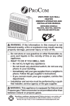
1
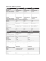
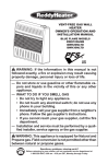
Vent-Free Gas Wall Heater
Infrared
WARNING:This appliance is
equipped for (Natural and Propane)
gas. Field conversion is not permitted
other than between natural or
propane gases.
Model # MD2TPA
MD3TPA
MD5TPA
MD3TPA-BB
MD5TPA-BB
CAUTION - FOR YOUR SAFETY
WARNING: IF THE INFORMATION IN THIS MANUAL IS NOT FOLLOWED
EXACTLY, A FIRE OR EXPLOSION MAY RESULT CAUSING PROPERTY
DAMAGE, PERSONAL INJURY, OR LOSS OF LIFE.
– Do not store or use gasoline or other flammable vapors and liquids in vicinity of
this or any other appliance.
WHAT TO DO IF YOU SMELL GAS
• Do not try to light any appliance.
• Do not touch any electrical switch; do not use any phone in your building.
• Immediately call your gas supplier from a neighbor’s phone. Follow the gas
supplier’s instructions.
• If you cannot reach your gas supplier, call the fire department.
– Installation and service must be performed by a qualified installer, service agency
or the gas supplier.
This is an unvented gas-fired heater. It uses air (oxygen) from the room in which it is
installed. Provisions for adequate combustion and ventilation air must be provided.
Refer to Air For Combustion and Ventilation section on page 8 of this manual.
INSTALLER: Leave this manual with the appliance. CONSUMER: Retain this manual
for future reference.
This appliance may be installed in an aftermarket, permanently located, manufactured
(mobile) home, where not prohibited by local codes. This appliance is only for use with
propane or natural gas. This appliance is equipped with a simple means to switch
between propane and natural gas. Field conversion by any other means including the
use of a kit is not permitted.
Questions about installation, operation, or troubleshooting? Before returning to your retailer, contact our
customer service department at 1-877-886-5989, 8:00 a.m.- 4:30p.m., EST, Monday-Friday or e-mail
[email protected].
PC-MD2TPA-1202-B
TABLE
OFCONTENTS
CONTENTS
TABLE OF
Important Safety Information ..............................................................................................................................4
Product Features................................................................................................................................................6
Preparing for Installation.....................................................................................................................................7
Air for Combustion & Ventilation.........................................................................................................................8
Installation ........................................................................................................................................................11
Operation .........................................................................................................................................................17
Care and Maintenance .................................................................................................................................20
Troubleshooting .................................................................................................................................21
Replacement Parts.............................................................................................................................24
WARNING: READ THE INSTALLATION & OPERATION INSTRUCTIONS BEFORE USING THIS APPLIANCE.
IMPORTANT: Read this owner’s manual carefully and completely before trying to assemble, operate, or service this
heater. Improper use of this heater can cause serious injury or death from burns, fire, explosion, and carbon
monoxide poisoning.
2
PRODUCT SPECIFICATIONS
MODEL
MD2TPA
MD3TPA
MD5TPA
BTU (available)
12,000
20,000
30,000
Gas Type
Using Natural Gas
Using Natural Gas
Using Natural Gas
Pressure Regulator Setting
6 in. W.C.
6 in. W.C.
6 in. W.C.
Inlet Gas Pressure* (inches of water) * For purposes of input adjustment.
Maximum
10.5 in.
10.5 in.
10.5 in.
Minimum *
7 in.
7 in.
7 in.
BTU (available)
10,000
18,000
30,000
Gas Type
Using Propane Gas
Using Propane Gas
Using Propane Gas
Pressure Regulator Setting
10 in. W.C.
10 in. W.C.
10 in. W.C.
Inlet Gas Pressure* (inches of water) * For purposes of input adjustment.
Maximum
14 in.
14 in.
14 in.
Minimum *
11 in.
11 in.
11 in.
Ignition
Electric Piezo
Electric Piezo
Electric Piezo
Heater
19 1/8 × 14 1/8 × 7 1/8
23 1/2 × 19 1/4 × 8 3/4
23 1/2 x 26 5/8 x 8 3/4
Carton
22 ×16 3/4 × 8 7/8
25 3/4 × 21 3/4 × 10
25 3/4 x 28 1/2 x 10
Heater
15.1
21.6
28.1
Shipping
18.1
25.6
33.1
MODEL
MD3TPA-BB
MD5TPA-BB
BTU (available)
20,000
30,000
Gas Type
Using Natural Gas
Using Natural Gas
Pressure Regulator Setting
6 in. W.C.
6 in. W.C.
Dimensions, Inches (HxWxD)
Weight (Pounds)
Inlet Gas Pressure* (inches of water) * For purposes of input adjustment.
Maximum
10.5 in.
10.5 in.
Minimum *
7 in.
7 in.
BTU (available)
18,000
30,000
Gas Type
Using Propane Gas
Using Propane Gas
Pressure Regulator Setting
10 in. W.C.
10 in. W.C.
Inlet Gas Pressure* (inches of water) * For purposes of input adjustment.
Maximum
14 in.
14 in.
Minimum *
11 in.
11 in.
Ignition
Electric Piezo
Electric Piezo
Heater
23 1/2 × 19 1/4 × 8 3/4
23 1/2 x 26 5/8 x 8 3/4
Carton
25 3/4 × 21 3/4 × 10
25 3/4 x 28 1/2 x 10
Heater
24.5
31
Shipping
28.5
36
Dimensions, Inches (HxWxD)
Weight (Pounds)
3
IMPORTANT
SAFETY
IMPORTANT
SAFETYINFORMATION
INFORMATION
IMPORTANT: Read this owner’s manual carefully and completely before trying to assemble, operate, or service this
heater. Improper use of this heater can cause serious injury or death from burns, fire, explosion, electrical shock,
and carbon monoxide poisoning.
Only a qualified installer, service agent, or local gas supplier may install and service this product.
WARNING: Do not store or use gasoline or other flammable vapors and liquids in the vicinity of this or any
other appliance.
WARNING: This appliance can be used with propane or natural gas. It is shipped from the factory adjusted for
use with propane.
CARBON MONOXIDE POISONING: Early signs of carbon monoxide poisoning resemble the flu with headache,
dizziness and/or nausea. If you have these signs, heater may not be working properly. Get fresh air at once!
Have heater serviced. Some people - pregnant women, persons with heart or lung disease, anemia, those
under the influence of alcohol, those at high altitude - are more affected by carbon monoxide than others.
NATURAL AND PROPANE/LP GAS: Natural and Propane/LP gas are odorless. An odor-producing agent is
added to the gas. The odor helps you detect a gas leak. However, the odor added to the gas can fade. Gas may
be present even though no odor exists.
WARNING: Any change to this heater or its controls can be dangerous.
WARNING: Do not use any accessories not approved for use with this heater.
WARNING: Carefully supervise young children when they are in the room with the heater.
WARNING: Make sure grill guard is in place before running heater.
WARNING: Keep the appliance area clear and free from combustible materials, gasoline, and other flam
mable vapors and liquids.
WARNING: Due to high temperatures, the appliance should be located out of traffic and away from furniture
and draperies.
WARNING: Heater becomes very hot when running . Keep children and adults away from hot surfaces to
avoid burns or clothing ignition. Heater will remain hot for a time after shutoff. Allow surfaces to cool before
touching.
WARNING: Do not place clothing or other flammable material on or near the appliance. Never place any
objects in the heater.
1. Do not place Propane/LP supply tank(s) inside any structure. Propane/LP supply tank(s) must be Placed
outdoors.
2. This heater shall not be installed in a bedroom or bathroom, or the place which the strong wind would shut down
the appliance.
3. This heater needs fresh air ventilation to run properly. This heater has an Oxygen Depletion Sensing (ODS)
safety shutoff system. The ODS shuts down the heater if not enough fresh air is available. See Air for
Combustion and Ventilation, pages 8 through 10. If heater keeps shutting off, see Troubleshooting, pages 21
through 23.
4. Keep all air openings in front and bottom of heater clear and free of debris. This will ensure enough air for
proper combustion.
4
5. If heater shuts off, do not relight until you have provided fresh, outside air. If heater keeps shutting off, have it
serviced.
6.
Do not run heater:
• Where flammable liquids or vapors are used or stored.
• Under dusty conditions.
7. Before using furniture polish, wax, carpet cleaner, or similar products, turn heater off. If heated, the vapors from
these products may create a white powder residue within burner box or on adjacent walls or furniture.
8. Always run heater with control knob at PILOT/IGN, LOW or HIGH locked positions. Never set control knob be
tween locked positions. Poor combustion and higher levels of carbon monoxide may result.
9. Do not use heater if any part has been under water. Immediately call a qualified service technician to inspect
the room heater and to replace any part of the control system and any gas control which has been under water.
10.Turn off and unplug heater and let cool before servicing. Only a qualified service person should service and repair
heater.
11. Operating heater above elevations of 4,500 feet could cause pilot outage.
12. To prevent performance problems, do not use propane/LP fuel tank of less than 100 lbs. capacity.
QUALIFIED INSTALLING AGENCY
Only a qualified agency should install and replace gas piping, gas utilization equipment or accessories, and repair and
equipment servicing.The term “qualified agency” means any individual, firm, corporation, or company that either in
person or through a representative is engaged in and is responsible for:
a) Installing, testing, or replacing gas piping or
b) Connecting, installing, testing, repairing, or servicing equipment; that is experienced in such work; that is familiar
with all precautions required; and that has complied with all the requirement of the authority having jurisdiction.
5
PRODUCT FEATURES
SAFETY PILOT
This heater has a pilot with an Oxygen Depletion Sensing (ODS) safety shutoff system. The ODS/pilot shuts off the
heater if there is not enough fresh air.
PIEZO IGNITION SYSTEM
This heater is equipped with piezo ignitor. This system requires no matches, batteries, orother sources to light heater.
2 GAS OPTIONS CAPABLE
Your heater is equipped to operate on either Propane or Natural gas. The heater is shipped from the factory ready for
connecting to Propane. The heater can easily be changed to Natural gas by having your qualified installer follow the
instructions on page 15 and the markings on the heater.
THERMOSTATIC CONTROL ON THERMOSTAT MODEL
These heaters have a control valve with a thermostat sensing bulb. This results in the greatest heater comfort and
may result in lower gas bills.
State of Massachusetts: The installation must be made by a licensed plumber or gas fitter in the Commonwealth
of Massachusetts. Sellers of unvented propane or natural gas-fired supplemental room heaters shall provide to
each purchaser a copy of 527 CMR 30 upon sale of the unit.
In the State of Massachusetts, unvented propane or natural gas-fired space heaters shall be prohibited in
bedrooms and bathrooms.
In the State of Massachusetts the gas cock must be a T-handle type. The State of Massachusetts requires that
a flexible appliance connector cannot exceed three feet in length.
LOCAL CODES
Install and use heater with care. Follow all local codes. In the absence of local codes, use the latest edition of The
National Fuel Gas Code, ANSI Z223.1/ NFPA 54.
*Available from:
American National Standards Institute, lnc.
1430 Broadway
New York, NY 10018
National Fire Protection Association, lnc.
1 Batterymarch Park
Quincy, MA 02269-9101
6
PREPARING FOR INSTALLATION
Before beginning assembly or operation of the product, make sure all parts are present. Compare parts with package
contents list and diagram above. If any part is missing or damaged, do not attempt to assemble, install or operate the
product. Contact customer service for replacement parts.
Before installing heater, make sure you have the items listed below:
• piping (check local codes)
• sealant (resistant to natural gas and propane/LP gas)
• equipment shutoff valve*
• test gauge connection*
• sediment trap
• tee joint
• pipe wrench
• flexible gas hose (check local codes)
* A CSA design-certified equipment shutoff valve with
1/8-inch NPT tap is an acceptable alternative to test
gauge connection. Purchase the optional CSA designcertified equipment shutoff valve from your dealer.
UNPACKING
1.
2.
3.
Figure 1 - Vent-Free Gas Heater
Remove heater from carton.
Remove all protective packaging applied to heater for shipping
Check heater for any shipping damage. If heater is damaged, promptly inform dealer where you bought heater.
WATER VAPOR: A BY-PRODUCT OF UNVENTED ROOM HEATERS
Water vapor is a by-product of gas combustion. An unvented room heater produces approximately one (1) ounce
(30 mL) of water for every 1,000 BTUs (.3 KWs) of gas input per hour. Unvented room heaters are recommended as
supplemental heat (a room) rather than a primary heat source (an entire house). In most supplemental heat applications, the water vapor does not create a problem. In most applications, the water vapor enhances the low humidity
atmosphere experienced during cold weather.
The following steps will help ensure that water vapor does not become a problem.
1. Be sure the heater is sized properly for the application, including ample combustion air and circulation air.
2. If high humidity is experienced, a dehumidifier may be used to help lower the water vapor content of the air.
3. Do not use an unvented room heater as the primary heat source.
7
AIR FOR COMBUSTION AND VENTILATION
WARNING: If the area in which the heater may be operated does not meet the required volume for indoor
combustion air, combustion and ventilation air shall be provided by one of the methods described in the National
Fuel Gas Code, ANSI Z223.1/NFPA 54, the International Fuel Gas Code, or applicable local codes.
Providing Adequate Ventilation
All spaces in homes fall into one of the three following ventilation classifications:
1. Unusually Tight Construction
2. Unconfined Space
3. Confined Space
The information on pages 8 through 10 will help you classify your space and provide adequate ventilation.
Confined and Unconfined Space
A confined space is a space whose volume is less than 50 cu. ft. per 1,000 BTU/hr (4.8 m^3 per kw) of the aggregate
input rating of all appliances installed in that space and an unconfined space as a space whose volume is not less than
50 cubic feet per 1,000 BTU/hr (4.8 m^3 per kw) of the aggregate input rating of all appliances installed in that space.
Rooms connecting directly with the space in which the appliances are installed*, through openings not furnished with
doors, are considered a part of the unconfined space.
This heater shall not be installed in a confined space or unusually tight construction unless provisions are provided for
adequate combustion and ventilation air.
* Adjoining rooms are connecting only if there are doorless passageways or ventilation grills between them.
Unusually Tight Construction
The air that leaks around doors and windows may provide enough fresh air for combustion and ventilation. However, in
buildings of unusually tight construction, you must provide additional fresh air.
Unusually tight construction is defined as construction where:
a) Walls and ceilings exposed to the outside atmosphere have a continuous water vapor retarder with a rating of one
perm (6×10-11kg per pa-sec-m2) or less with openings gasketed or sealed and
b) Weather stripping has been added on openable windows and on doors and
c) Caulking or sealants are applied to areas such as joints around window and door frames, between sole plates and
floors, between wall ceiling joints, between wall panels, at penetrations for plumbing, electrical, and gas lines, and
at other openings.
If your home meets all of the three criteria above, you must provide additional fresh air. See “Ventilation Air From
Outdoors”. If your home does not meet all of the three criteria above, proceed to “Determining Fresh-Air Flow For
Heater Location”.
8
DETERMINING FRESH-AIR FLOW FOR HEATER LOCATION
Determining if You Have a Confined or Unconfined Space
Use this worksheet to determine if you have a confined or unconfined space.
Space: Includes the room in which you will install heater plus any adjoining rooms with doorless passageways or
ventilation grills between the rooms.
1. Determine the volume of the space Length × Width × Height =
cu. ft. (volume of space)
Example: Space size 20 ft. (length) × 16 ft. (width)×8 ft. (ceiling height) =2560 cu. ft. (volume of space)
If additional ventilation to adjoining room is supplied with grills or openings, add the volume of these rooms to
the total volume of the space.
2. Divide the space volume by 50 cubic feet to determine the maximum BTU/hr the space can support.
(volume of space) ÷ 50 cu. ft. =(Maximum BTU/hr the space can support)
3. Add the BTU/hr of all fuel burning appliances in the space.
Vent-free heater
Gas water heater*
Gas furnace
Vented gas heater
Gas heater logs
Other gas appliances* +
Total
=
BTU/hr
BTU/hr
BTU/hr
BTU/hr
BTU/hr
BTU/hr
BTU/hr
Example:
Gas water heater 30,000 BTU/hr
Vent-free heater + 26,000 BTU/hr
Total
= 56,000 BTU/hr
*Do not include direct-vent gas appliances. Direct-vent draws combustion air from the outdoors and vents to the
outdoors.
4. Compare the maximum BTU/hr the space can support with the actual amount of
BTU/hr used
BTU/hr (maximum the space can support)
BTU/hr (actual amount of BTU/hr used)
Example : 51,200 BTU/hr (maximum the space can support)
56,000 BTU/hr (actual amount of BTU/hr used)
The space in the above example is a confined space because the actual BTU/hr used is more than the maximum BTU/
hr the space can support.
You must provide additional fresh air. Your options are as follows:
a) Rework worksheet, adding the space of an adjoining room. If the extra space provides an unconfined space,
remove door to adjoining room or add ventilation grills between rooms. See “ Ventilation Air From Inside Building ”
on next page.
b) Vent room directly to the outdoors. See “ Ventilation Air From Outdoors ” on next page.
c) Install a lower BTU/hr heater if lower BTU/hr size makes room unconfined. If the actual BTU/hr used is less
than the maximum BTU/hr the space can support, the space is an unconfined space. You will need no
additional fresh air ventilation.
9
WARNING: If the area in which the heater may be
operated does not meet the required volume for indoor
combustion air, combustion and ventilation air shall
be provided by one of the methods described in the
NATIONAL FUEL GAS CODE, ANSI Z223.1/
NFPA 54, the INTERNATIONAL FUEL GAS CODE, or
applicable local codes.
Ventilation Air From lnside Building
This fresh air would come from an adjoining unconfined
space. When ventilating to an adjoining unconfined
space, you must provide two permanent openings: one
within 12 inches of the ceiling and one within 12 inches
of the floor on the wall connecting the two spaces
(see options 1 and 2, Figure 2). You can also remove
the door into adjoining room (see option 3, Figure 2).
Follow the National Fuel Gas Code. ANSI Z223.1/
NFPA 54, Air for Combustion and Ventilation for
required size of entilation grills or ducts.
Figure 2 - Ventilation Air from Inside Building
NOTE: Base not included. Not for use in
bedrooms or bathrooms.
Ventilation Air From Outdoors
Provide extra fresh air by using ventilation grills or
ducts. You must provide two permanent openings: one
within 12 inches of the ceiling and one within 12 inches
of the floor. Connect these items directly to the outdoors
or spaces open to the outdoors. These spaces include
attics and crawl spaces. Follow the National Fuel Gas
Code, ANSI Z223.1/ NFPA 54, Air for Combustion and
Ventilation for required size of ventilation grills or ducts.
IMPORTANT: Do not provide openings for inlet or
outlet air into attic if attic has a thermostat-controlled
power vent. Heated air entering the attic will activate
the power vent. Rework worksheet, adding the space of
the adjoining unconfined space. The combined spaces
must have enough fresh air to supply all appliances in
both spaces.
Figure 3 - Ventilation Air from Outdoors
10
INSTALLATION
NOTICE: This heater is intended for use as supplemental heat. Use this heater along with your primary heating
system. Do not install this heater as your primary heat source. If you have a central heating system, you may
run system’s circulating blower while using heater. This will help circulate the heat throughout the house. In the
event of a power outage, you can use this heater as your primary heat source.
CAUTION: If you install the heater in a home garage:
• Heater pilot and burner must be at least 18 inches above the floor.
• Place heater where moving vehicle will not hit it.
WARNING: A qualified service person must install heater. Follow all local codes.
WARNING: Never install the heater
• in a bedroom or bathroom
• in a recreational vehicle
• where curtains, furniture, clothing, or other flammable objects are less than 36 inches from the front, top, or
sides of the heater
• in high traffic areas
• in windy or drafty areas
CAUTION: This heater creates warm air currents. These currents move heat to wall surfaces next to heater.
Installing heater next to vinyl or cloth wall coverings or operating heater where impurities (such as tobacco
smoke, aromatic candles, cleaning fluids, oil or kerosene lamps, etc.) in the air exist, may cause walls to discolor.
IMPORTANT: Vent-free heaters add moisture to the air. Although this is beneficial, installing heater in rooms
without enough ventilation air may cause mildew to form too much moisture. See Air for Combustion and
Ventilation, pages 8 through 10
Check Gas Type
Be sure your gas supply is right for your heater.
Otherwise, call dealer where you bought the
heater for proper type heater.
Clearances To Combustibles
Carefully follow the instructions below. This
heater is a freestanding unit designed to be
mounted on a wall or set directly on the floor.
WARNING: Maintain the minimum clearances
shown in Figure 4. If you can, provide greater
clearances from floor, ceiling, and joining wall.
LOCATING HEATER
This heater is designed to be mounted on a wall.
For convenience and efficiency, install heater:
1) where there is easy access for operation,
inspection, and service.
2) In the coldest part of room.
Figure 4 - Mounting clearances as viewed from
front of heater (inches)
11
FASTENING HEATER TO WALL
Mounting Bracket
The mounting bracket is located on back panel of heater (see Figure 5).
It has been taped there for shipping. Remove mounting bracket from
back panel.
Removing Front Panel of Heater
1. Remove two screws near bottom corners of lower front panel .
2. Pull bottom of lower front panel forward, then down (see Figure 6).
Methods For Attaching Mounting Bracket To Wall
Use only the last hole on each end of mounting bracket to attach bracket
to wall. Attach mounting bracket to a wall only in one of two ways:
1. Attaching to wall stud: This method provides the strongest hold.
Figure 5 - Mounting Bracket Location
Insert mounting screws through mounting bracket and into wall studs.
2. Attaching to wall anchor: This method allows you to attach mounting
bracket to hollow walls (wall areas between studs) or to solid walls
(concrete or masonry).
3. Decide which method better suits your needs. Either method will provide
a secure hold for the mounting bracket.
Marking Screw Locations
1. Tape mounting bracket to wall where heater will be located.
Make sure mounting bracket is level.
Figure 6 - Mounting Bracket
Clearances (inches)
WARNING: Maintain minimum clearances shown in Figure 4. If you can, provide greater clearances from floor
and joining wall.
2. Mark screw locations on wall (see Figure 7).
Note: Mark only last hole on each end of mounting bracket. Insert mounting screws through these holes only.
3. Remove tape and mounting bracket from wall.
Attaching Mounting Bracket To Wall
Note: Wall anchors, mounting screws, and spacers are in hardware
package. The hardware package is provided with heater.
Attaching to Wall Stud Method
For attaching mounting bracket to wall studs:
1. Drill holes at marked locations using 9/64-inch drill bit.
2. Place mounting bracket onto wall. Line up last hole on
Model : MD2TPA
each end of bracket with holes drilled in wall.
3. Insert mounting screws through bracket and into wall studs.
4. Tighten screws until mounting bracket is firmly fastened to wall studs.
Model : MD3TPA, MD5TPA
MD3TPA-BB, MD5TPA-BB
12
Figure 7 - Mounting Bracket
Clearances (inches)
Attaching to Wall Anchor Method
For attaching mounting bracket to hollow walls (wall areas between studs)
or solid walls (concrete or masonry):
1. Drill holes at marked locations using 5/16-inch drill bit. For solid walls
(concrete or masonry), drill at least 1 inch deep.
2. Fold wall anchor as shown in Figure 8.
3. Insert wall anchor (wings first) into hole. Tap anchor flush to wall.
4. For thin walls (1/2 inch or less), insert red key into wall anchor. Push
red key to “pop” open anchor wings (see Figure 9).
Figure 8 - Folding Anchor
IMPORTANT: Do not hammer anchor key! For thick walls (over 1/2
inch thick) or solid walls, do not pop open wings.
5. Place mounting bracket onto wall. Line up last hole on each end of
bracket with wall anchors.
6. Insert mounting screws through bracket and into wall anchors.
7. Tighten screws until mounting bracket is firmly fastened to wall.
Placing Heater On Mounting Bracket
1. Locate two horizontal slots on back panel of heater (see Figure 10).
Figure 9 - Popping Open
Anchor Wing For Thin Walls
2. Place heater onto mounting bracket. Slide horizontal slots onto standout tabs on mounting bracket.
Installing Bottom Mounting Bracket
1. Install bottom bracket to heater bottom with two screws. It may be
more convenient to remove heater from wall bracket to attach.
2. Place heater on wall mounting bracket.
3. Mark screw locations on wall.
4. Remove heater from mounting bracket.
5. If installing bottom mounting screws into hollow or solid wall, install
wall anchors. Follow steps 1 through 4 under “Attaching To Wall Anchor Method”. If installing bottom mounting screw into wall stud, drill
holes at marked locations using 9/64-inch drill bit.
Figure 10 - Mounting Heater
Onto Mounting Bracket
6. Replace heater onto mounting bracket.
7. Using the longest screw and plastic spacer provided, drive screw from
the inside of the heater body through hole shown in figures 11A and
11B and into the hole at the end of the plastic spacer. (For MD2TPA
see Figure 11A), (For MD3TPA,MD3TPA-BB,MD5TPA,and MD5TPABB see Figure 11B)
8. Tighten the screw until heater is firmly secured to wall. Do not overtighten spacer onto the wall. (For MD2TPA see Figure 11C), (For
MD3TPA,MD3TPA-BB,MD5TPA,and MD5TPA-BB see Figure 11D)
Screw
Shell
Plastic
Spacer
Figure 11A
Screw
Shell
Figure 11C
Figure 11D
13
Figure 11B
Plastic
Spacer
CONNECTING TO GAS SUPPLY
WARNING: A qualified service technician must connect heater to gas supply. Follow all local codes.
WARNING: This appliance requires a 3/8-inch NPT (National Pipe Thread) inlet connection to the pressure
regulator.
WARNING: Never connect heater to private (non-utility) gas wells. This gas is commonly known as wellhead gas.
WARNING: Do not over-tighten gas connections.
CAUTION: Use only new, black iron or steel pipe. Internally tinned copper tubing may be used in certain areas.
Check your local codes. Use pipe of 1/2-in. diameter or greater to allow proper gas volume to heater. If pipe is
too small, undue loss of pressure will occur.
NATURAL GAS MODELS:
CAUTION: Check your gas line pressure before connecting heater to gas line. Gas line pressure must be no
greater than 10.5 inches of water. If gas line pressure is higher, heater regulator damage could occur.
PROPANE MODELS:
CAUTION: Never connect heater directly to the gas supply. This heater requires an external regulator (not
supplied). Install the external regulator between the heater and gas supply.
CAUTION: Avoid damage to regulator. Hold gas regulator with wrench when connecting into gas piping and/or
fittings.
CAUTION: Use pipe joint sealant that is resistant to gas (Propane or Natural Gas).
Typical Inlet Pipe Diameters Use 3/8-inch black iron pipe or greater. Installation must include
an equipment shutoff valve, union, and plugged 1/8-inch NPT tap. Locate NPT tap within reach for test gauge
hook up. NPT tap must be upstream from heater (see Figure 12).
IMPORTANT: Install an equipment shutoff valve in an accessible location. The equipment shutoff valve is
for turning on or shutting off the gas to the appliance.
Figure 12 - Gas Connection (inches)
* Purchase the optional CSA design-certified equipment shutoff valve from your dealer.
14
Apply pipe joint sealant lightly to male threads. This will prevent excess sealant
from going into pipe. Excess sealant in pipe could result in clogged heater valves.
The installer must supply an external regulator. The external regulator will reduce
incoming gas pressure. You must reduce incoming gas pressure to between 11 and
14 inches of water. If you do not reduce incoming gas pressure, heater regulator
damage could occur. Install external regulator with the vent pointing down as shown
in Figure 13. Pointing the vent down protects it from freezing rain or sleet.
Install sediment trap in supply line as shown in Figure 12. Place sediment trap
where it is within reach for cleaning. Place sediment trap where trapped matter is
not likely to freeze. A sediment trap traps moisture and contaminants. This keeps
them from going into heater controls. If sediment trap is not installed or is installed
wrong, heater may not run properly.
Figure 13 - External Regulator with
Vent Pointing Down
INSTALLATION
Continued
CAUTION: Two gas line installations at the same time are prohibited. The access plate to the simple switching means
shall not be opened while the heater is in operation.
This appliance can be used with propane or natural gas. It is shipped from the factory adjusted for use with propane.
Only a qualified installer or service technician can perform gas selection and connecting to gas supply.
CAUTION: To avoid gas leakage at the inlet of regulator, a qualified installer or service technician must use
steel or metal hex plug with sealant.
WARNING: Do not attempt to access or change the setting of the fuel selection means
Access to and adjustment of the fuel selection means must only be performed by a qualified service person when
connecting this appliance to a specified fuel supply at the time of installation.
Change of the selector setting to other than the fuel type specified at the time of installation could damage this appliance and render it inoperable.
The instaler shall replace the access cover before completing the installation and operating this appliance.
For changing from propane to natural gas supply:
1. Remove top screw from cover plate, See Figure 14, and rotate to expose fuel selection device.
2. For NATURAL GAS, press knob using a flat screwdriver with a blade with thickness of a quarter and turn knob
clockwise
until the knob locks into the NG position (see Figure 15). Fuel selection device must be locked in
the NG position. Do not operate heater between locked positions!
3. Rotate and close cover over fuel selection device and reinstall screw.
4. Remove steel or metal hex plug (with wrench provided) from natural gas inlet of regulator and install into LP inlet of
regulator; use thread sealant to ensure that there are no leaks.
For changing from natural gas supply to propane supply:
1. Remove top screw from cover plate, See Figure 14, and rotate to expose fuel selection device.
2. For propane gas, press in knob using a flat screwdriver with a blade the thickness of a quarter and turn knob
counterclockwise
until the knob locks into the LP position, see Figure 16. Fuel selection device must be
locked in the LP position. Do not operate heater between locked positions.
3. Rotate and close cover over fuel selection device and reinstall screw.
4. Remove steel or metal hex plug from liquid propane inlet of regulator and install into NG inlet of regulator; use
thread sealant to assure there are no leaks.
15
Figure 14
Figure 15
Figure 16
CHECKING GAS CONNECTIONS
WARNING: Test all gas piping and connections for leaks after installing or servicing. Correct all leaks at once.
WARNING: Never use an open flame to check for a leak. Apply a mixture of liquid soap and water to all joints. If
bubbles form, there is a leak. Correct all leaks at once.
PRESSURE TESTING GAS SUPPLY PIPING SYSTEM
Test Pressures In Excess Of 1/2 PSIG (3.5kPa)
1. Disconnect heater with its appliance main gas valve (control valve) and equipment shutoff valve from gas supply
piping system. Pressures in excess of 1/2 PSIG will damage heater regulator.
2. Cap off open end of gas pipe where equipment shutoff valve was connected.
3. Pressurize supply piping system by either using compressed air or opening
gas supply valve.
4. Check all joints of gas supply piping system. Apply mixture of liquid soap
and water to gas joints. If bubbles form, there may be a leak.
5. Correct all leaks at once.
6. Reconnect heater and equipment shutoff valve to gas suply. Check
reconnected fittings for leaks.
Figure 17 - Equipment Shutoff Valve
Test Pressures Equal To or Less Than 1/2 PSIG (3.5 kPa)
1. Close equipment shutoff valve (see Figure 17).
2. Pressurize supply piping system by either using compressed air or
opening natural supply tank valve.
3. Check all joints from gas meter to equipment shutoff valve
(see Figure 18).
Apply mixture of liquid soap and water to gas joints. If bubbles
form, there is a leak.
Figure 18 - Fuel Supply
4. Correct all leaks at once.
16
Pressure Testing Heater Gas Connections
1. Open equipment shutoff valve (see Figure 17).
2. Open gas supply tank valve.
3. Make sure control knob of heater is in the OFF position.
4. Remove front panel.
5. Check all joints from equipment shutoff valve to control valve (see Figure 17). Apply mixture of liquid soap and
water to gas joints. If bubbles form, there may be a leak.
6. Correct all leaks at once.
7. Light heater (see Lighting Instructions on page 18). Check all other internal joints for leaks.
8. Turn off heater (see “To Turn Off Gas Appliance” on page 18).
9. Replace lower front panel.
OPERATION
FOR YOUR SAFETY READ BEFORE LIGHTING
WARNING: If you do not follow these instructions exactly, a fire or explosion may result causing property
damage, personal injury or loss of life.
A. When lighting the pilot, follow these instructions exactly.
B. BEFORE LIGHTING, smell all around the appliance area for gas. Be sure to smell next to the floor because
some gas is heavier than air and will settle on the floor.
C. Use only your hand to push in or turn the gas control knob. Never use tools. If the knob will not push in or turn
by hand, don’t try to repair it, call a qualified service technician or gas supplier. Forced or attempted repair may
result in a fire or explosion.
D. Do not use this appliance if any part has been under water. Immediately call a qualified service technician to
inspect the appliance and to replace any part of the control system and any gas control which has been under
water.
WHAT TO DO IF YOU SMELL GAS
• Do not try to light any appliance.
• Do not touch any electric switch, do not use any phone in your building.
• Immediately call your gas supplier from a neighbor’s phone. Follow the gas supplier’s instructions.
• If you cannot reach your gas supplier, call the fire department.
17
LIGHTING INSTRUCTIONS
1.STOP! Read the safety information on the side of the heater.
2. Make sure equipment shutoff valve is fully open.
3. Turn control knob clockwise
to the OFF position.
4. Wait five (5) minutes to clear out any gas. Then smell for gas, including near the floor. If you smell gas, STOP! Do
not try to light any appliance. Do not touch electrical switch or use any phone in the building. Immediately contact
gas supplier from a neighbor’s phone. Follow gas supplier’s instructions. If you can’t reach the gas supplier, call the
fire dept. If you don’t smell gas, go to the next step.
5. Turn control knob counterclockwise
19).
to the PILOT position.Press in control knob for five (5) seconds (see Figure
Note: The first time that the heater is operated after connecting the gas supply,the control knob should be depressed
for about thirty (30) seconds.This will allow air to bleed from the gas sysystem. If pilot does not stay lit, refer to
Troubleshooting, pages 21 through 23. Also contact a qualified service technician or gas supplier for repairs. Until
repairs are made, light pilot with match.
• If control knob does not pop up when released, contact a qualified service technician or gas supplier for repairs.
6. With control knob pressed in, push down and release ignitor button. This will light pilot. The pilot is attached to
the front of burner. The pilot can be seen through the gill. If needed, keep pressing ignitor button until pilot lights.
Note: If pilot does not stay lit, refer to Troubleshooting, pages 21 through 23. Also contact a qualified service
technician or gas supplier for repairs. Until repairs are made, light pilot with match. To light pilot with match, see “Manual
Lighting Procedure”.
7. Keep control knob pressed in for 30 seconds after lighting pilot. After 30 seconds, release control knob.
If control knob does not pop up when released, contact a qualified service technician or gas supplier for repairs.
Note: If pilot goes out, repeat steps 3 through 7. This heater has a safety interlock system. Wait one (1) minute
before lighting pilot again.
8. Turn control knob counterclockwise
any heat level between 1 and 5.
to desired heating level. The main burner should light. Set control knob to
CAUTION: Do not try to adjust heating levels by using the equipment shutoff valve.
THERMOSTAT CONTROL OPERATION
The thermostatic control used on this model differs from standard thermostats. Standard thermostats simply turn the burner on and off. The
thermostat used on this heater senses the room temperature. At times
the room may exceed the set temperature. If so, the burner will shut
off. The burner will cycle back on when room temperature drops below
the set temperature. The control knob can be set to any comfort level
between HIGH (5) and LOW (1).
TO TURN OFF GAS TO APPLIANCE
Shutting Off Heater
Turn control knob clockwise
to the OFF position.
Fig. 20
Shutting Off Burner Only (pilot stays lit )
Turn control knob clockwise
Figure 19 - Control Knob in the
OFF Position
to the PILOT position.
CAUTION: Do not try to adjust heating levels by
using the equipment shutoff valve. Slightly press in control
knob and turn counterclockwise
to your desired heat
level (1, 2, 3, 4, or 5). (see Fig. 20)
18
INSPECTING BURNER
Check pilot flame pattern and burner flame pattern often.
PILOT FLAME PATTERN
Figure 21 shows a correct pilot flame pattern. Figure 22 shows a incorrect pilot flame pattern. The incorrect pilot
flame is not touching the thermocouple. This will cause the thermocouple to cool, which shuts the heater off. If
pilot flame pattern is incorrect:
• turn heater off (see “To Turn Off Gas to Appliance” on page 18)
• see Troubleshooting pages 21 through 23.
Figure 22 - Incorrect Pilot Flame Pattern
Figure 21 - Correct Pilot Flame Pattern
WARNING: If yellow tipping occurs, your heater could produce increased levels of carbon monoxide. If
burner flame pattern shows yellow tipping, follow instructions at bottom of this page.
Notice: Do not mistake orange flames with yellow tipping. Dirt or other fine particles enter the heater and burn
causing brief patches of orange flame.
BURNER FLAME PATTERN
Figure 23 shows a correct burner flame pattern. Figure 24 shows an incorrect burner flame pattern. If burner
flame pattern is incorrect then:
• turn heater off (see “To Turn Off Gas to Appliance” on page 18).
• see Troubleshooting, pages 21 through 23
Fig. 22 - Correct Pilot Flame Pattern with Control
Knob Set to High Flame (5)
Fig. 22 - Incorrect Pilot Flame Pattern with
Control Knob Set to High Flame (5)
19
CARE AND MAINTENANCE
WARNING: Turn off heater and let cool before servicing
CAUTION: You must keep control areas, burner, and circulating air passageways of heater clean. Inspect
these areas of heater before each use. Have heater inspected yearly by a qualified service technician. Heater
may need more frequent cleaning due to excessive lint from carpeting, bedding material, pet hair, etc.
ODS/PILOT AND BURNER
• Use a vacuum cleaner, pressurized air, or a small, soft bristled brush to clean.
CLEANING BURNER PILOT AIR INLET HOLE
We recommend that you clean the unit every 2,500 hours of operation or every three months. We also recommend
that you keep the burner tube and pilot assembly clean and free of dust and dirt. To clean these parts we recommend
using compressed air no greater than 30 PSl. Your local computer store, hardware store, or home center may carry
compressed air in a can. You can use a vacuum cleaner in the blow position. If using compressed air in a can, please
follow the directions on the can. If you don’t follow directions on the can, you could damage the pilot assembly.
1. Shut off the unit, including the pilot. Allow the unit to cool for at least thirty minutes.
2. Inspect burner and pilot for dust and dirt.
3. Blow air through the ports/slots and holes in the burner. Also clean the pilot assembly. A yellow tip on the pilot
flame indicates dust and dirt in the pilot assembly. There is a small pilot air inlet hole about two inches from
where the pilot flame comes out of the pilot assembly (see Figure 25). With the unit off, lightly blow air through
the air inlet hole. You may blow through a drinking straw if compressed air is not available.
CABINET
Air Passageways
• Use a vacuum cleaner or pressurized air to clean.
Exterior
• Use a soft cloth dampened with a mild soap and water mixture.
• Wipe the cabinet to remove dust.
Figure 25 - Pilot Inlet Air Hole
20
TROUBLESHOOTING
WARNING: If you smell gas:
• Shut off gas supply.
• Do not try to light any appliance.
• Do not touch any electrical switch; do not use any phone in your building.
• Immediately call your gas supplier from a neighbor’s phone. Follow the gas supplier’s instructions.
• If you cannot reach your gas supplier, call the fire department.
IMPORTANT: Operating heater where impurities in air exist may create odors. Cleaning supplies, paint, paint remover, cigarette smoke, cements and glues, new carpet or textiles, etc., create fumes. These fumes may mix with
combustion air and create odors.
WARNING: Only a qualified service technician should service and repair heater.
CAUTION: Never use a wire, needle, or similar object to clean ODS/pilot. This can damage ODS/ pilot unit.
Note: All troubleshooting items are listed in order of operation.
Problem
When ignitor button is
pressed in, there is no spark
at ODS/pilot
Possible Cause
1. Ignitor electrode is positioned
wrong. Ignitor electrode is
broken.
2. Ignitor electrode is not
connected to ignitor cable.
3. Ignitor cable is pinched or
wet.
4. Broken ignitor cable.
5. Bad piezo ignitor.
When ignitor button is pressed in
1. Gas supply is turned off or
equipment shutoff valve is
there is a spark at ODS/pilot but no
closed.
ignition.
2. Control knob not fully
pressed in while pressing
ignitor button.
3. Air in gas lines when installed.
4. ODS / pilot is clogged.
5. Gas regulator setting is not correct.
6. Control knob not in PILOT position.
7. Depleted gas supply (propane).
21
Corrective Action
1. Replace electrode.
2. Replace ignitor cable
3. Free ignitor cable if pinched
by any metal or tubing.
Keep ignitor cable dry.
4. Replace ignitor cable.
5. Replace piezo ignitor.
1. Turn on gas supply or open
equipment shutoff valve.
2. Fully press in control knob while
pressing ignitor button.
3. Continue holding down control
knob. Repeat igniting operation
until air is removed.
4. Clean ODS/pilot (see Care
and Maintenance, page 20) or
replace ODS/pilot assembly.
5. Replace gas regulator.
6. Turn control knob to PILOT
position.
7. Contact local propane/LP gas
company.
Problem
ODS/pilot lights but flame goes out
when control knob is released.
Possible Cause
1. Control knob is not fully
pressed in.
2. Control knob is not pressed
in long enough.
1. Press in control knob
fully.
2. After ODS/pilot lights,
keep control knob pressed
in 30 seconds.
3. Equipment shutoff valve is
not fully open.
4. Thermocouple connection is
loose.
3. Fully open equipment
shutoff valve.
4. Hand tighten until snug,
and then tighten ¼ turn
more.
5. Replace thermocouple.
6. Contact customer service.
5. Thermocouple damaged.
6. Control valve damaged.
Burner(s) does not light afterODS/
pilot is lit
Corrective Action
1. Burner orifice is clogged.
2. Burner orifice diameter is
too small.
3. Inlet gas pressure is too low.
1. Burner orifice (see
Care and Maintenance,
page 20) or contact
customer service.
2. Contact customer service.
3. Contact your gas supplier.
Delayed ignition of burner(s).
1. Manifold pressure is too low.
2. Burner orifice is clogged.
1. Contact your gas supplier.
2. Clean burner (see
Care and Maintenance,
page 20) or Contact
customer service.
Burner backfiring during combustion
1. Burner orifice is clogged or
damaged.
1. Clean burner orifice (see
Care and Maintenance,
page 20) or contact
customer service.
2. Contact dealer or customer
service.
3. Replace gas regulator.
2. Burner is damaged.
3. Gas regulator is damaged.
High yellow flame during burner
combustion
1. Not enough air.
2. Gas regulator is defective.
3. Inlet gas pressure is too low.
Gas odor during
combustion.
1. Foreign matter between
control valve and burner.
2. Gas leak. (See Warning
Statement at top of
page 21).
22
1. Check burner for dirt and
debris. If found, clean
burner (see Care and
Maintenance, page 20).
2. Replace gas regulator.
3. Contact your gas supplier.
1. Take apart gas tubing
and remove foreign matter.
2. Locate and correct all
leaks (see “Checking
Gas Connections,”
page 14).
Problem
Possible Cause
Corrective Action
Slight smoke or odor during initial
operation
1. Residues from
manufacturing process.
1. Problem will stop after a few
hours of operation.
Heater produces a whistling noise
when burner is lit.
1. Turning control knob to
high (5) position when
burner is cold.
2. Air in gas line.
1. Turn control knob to low (1)
position and let warm up for a
minute.
2. Operate burner until air is removed
from line. Have gas line checked by
local propane/LP gas company.
3. Observe minimum installation
clearances (Fig. 4, page 11)
4. Clean burner (see Care and
Maintenance, page 20) or contact
customer service.
3. Air passageways on
heater are blocked.
4. Dirty or partially clogged
burner orifice.
Heater produces a clicking/ticking
noise just after burner is lit or shut
off.
1. Metal is expanding while
heating or contracting
while cooling.
1. This is common with most heaters.
If noise is excessive, contact
qualified service technician.
White powder residue forming
within burner box or on adjacent
walls or furniture
1. When heated, the
vapors from furniture
polish, wax, carpet
cleaners, etc., turn into
white powder residue.
1. Turn heater off when using furniture
polish, wax, carpet cleaner or
similar products.
Heater produces unwanted odors.
1. Heater is burning vapors
from paint, hair spray,
glues, etc. See
IMPORTANT statement,
page 21.
2. Gas leak. See Warning
Statement at the top of
page 21.
3. Low fuel supply.
1. Ventilate room. Stop using odor
causing products while heater is
running.
Heater shuts off in use
(ODS operates).
1. Not enough fresh air is
available.
2. Low line pressure.
3. ODS/pilot is partially
clogged.
1. Open window and/or door for
ventilation.
2. Contact local gas supplier.
3. Clean ODS/pilot (see Care
and Maintenance, page 20).
Gas odor exists even
when control knob is in OFF position.
1. Gas leak. See Warning
Statement at top of
page 21.
2. Control valve is
defective.
1. Locate and correct all leaks
(see “Checking Gas Connections”,
page 14).
2. Contact customer service.
Moisture/condensation
noticed on windows.
1. Not enough combustion/
ventilation air.
1. Refer to “Air for Combustion and
Ventilation” requirements, page 8.
23
2. Locate and correct all leaks (see
“Checking Gas Connections,”
page 14).
3. Refill supply tank (Propane /LP
models).
IMPORTANT SAFETY INFORMATION
REPLACEMENT PARTS
NOTE: Use only original replacement parts. This will protect your warranty coverage for parts replaced under
warranty.
PARTS UNDER WARRANTY
Contact authorized dealers of this product. If they can’t supply original replacement parts, call Customer Service toll
free at (877)886-5989 for referral information.
When calling Customer Service or your dealer, have ready:
•
Your name
•
Your address
•
Model and serial number of your heater
•
How heater was malfunctioning
•
Type of gas used (Propane/LP or Natural gas/NG)
•
Purchase date
•
Usually, we will ask you to return the defective part to the factory
PARTS NOT UNDER WARRANTY
Contact authorized dealers of this product. If they can’t supply original replacement part(s) call Customer Service
toll free at (877)886-5989 for referral information.
When calling Customer Service have ready:
•
Model number of your heater
•
The replacement part number
ACCESSORIES
Purchase these heater accessories from your local dealer. If
they can not supply these accessories, contact PRO-COM
for information.
figure 1
EQUIPMENT SHUTOFF VALVE
For all models. Equipment shutoff valve with 1/8 in. NPT tap.
(see figure 1)
Optional FAN Kit
The optional fan kit, part PF06-YJLF-BMB fits (model #
MD3TPA, MD5TPA, MD3TPA-BB, MD5TPA-BB). The fan has
3 settings ON/OFF/Auto. Please refer to PF06-YJLF-BMB
instructions. (see figure 2)
figure 2
FLOOR MOUNTING STAND
For locating heater on the floor, away from a wall. Complete
installation instructions provided with floor
mounting stand. (see figure 3)
24
figure 3
PARTS LIST (MD2TPA)
This list contains replaceable parts for your heater. When ordering replacement parts, follow the instructions listed
under Replacement Parts on page 24 of this manual.
PART
PART #
DESCRIPTION
QTY
LP
NG
1
MB10053-2DP-W
Cabinet Assembly
1
1
2
ML161-03
Reflector Unite
1
1
3
MB29003
Grill Guard
1
1
4
MB09003
Lower Front Panel Assembly
1
1
5
DFPB-2B-MB
Burner Can Assembly
1
1
6
PF-MED
ODS Bracket
1
1
7
NDD0308-800-1
DF ODS
1
1
8
MB40023DPN
ODS OUTIET TUBE(NG)
1
1
9
MB40023DPL
ODS OUTIET TUBE(LP)
1
1
10-1
ML090-03N
INJECTOR (INNER)
1
1
10-2
ML090-03L
INJECTOR (OUTER)
1
1
11
LHY-P-300
GAS SELECTOR VALVE ASSEMBLY
1
1
12
ML029-01
MAIN VALVE NUT
1
1
13
MDL304B
VALVE KNOB
1
1
14
MB40013DP
MAIN OUTLET TUBE ASM
1
1
15
MB40023DP
ODS/PILOT GAS TUBE ASM
1
1
16
SIT544-130-B
THERMOSTAT VALVE ASM
1
1
17
ML111-02A
THERMOSTAT VALVE BASE
1
1
18
MB40003DP
MAIN INLET TUBE ASM
1
1
19
RV83FI-6/10
DF REGULATOR
1
1
20
MML231-01
REGULATOR BRACKET
1
1
21
PF120820
REGULATOR PLUG
2
2
22
ML083-03
IGNITOR
1
1
23
MDL303-02A-W
GAS SELECTOR VALVE COVER
1
1
24
MB060-02
MOUNTING BRACKET ASM
1
1
PART AVAILABLE----NOT SHOWN
MB28001DP
Hardware Bag Assembly
1
1
ML070-03DP
Rating Label
1
1
ML065-01
Thermostat Sensing Bulb Clip
1
1
25
ILLUSTRATED PARTS
MD2TPA
24
22
16
1
17
18
23
14
13
5
11
9 12
13
2
3
6
7
8
10-1
10-2
9
4
18
20
19
21
26
15
14
8
PARTS LIST (MD3TPA)
This list contains replaceable parts for your heater. When ordering replacement parts, follow the instructions listed
under Replacement Parts on page 24 of this manual.
PART
MD3TPA
DESCRIPTION
PART #
QTY
LP
NG
1
MB10052-3DP-W
Cabinet Assembly
1
1
2
MB11052-3DP
Reflector Unite
1
1
3
MB29002
Grill Guard
1
1
4
MB09002
Lower Front Panel Assembly
1
1
5
DFPB-3B
Burner Can Assembly
1
1
6
PF-MED
Ods Bracket
1
1
7
NDD0308-800-1
DF ODS
1
1
8
MB40022DPN
ODS Outiet Tube(NG)
1
1
9
MB40022DPL
ODS Outiet Tube(LP)
1
1
10-1
ML090-02L
Injector (Inner)
1
1
10-2
ML090-02N
Injector (Outer)
1
1
11
LHY-P-300
Gas Selector Valve Assembly
1
1
12
ML029-01
Main Valve Nut
1
1
13
MDL304B
Valve Knob
1
1
14
MB40012DP
Main Outlet Tube Asm
1
1
15
MB40022DP
ODS/Pilot Gas Tube Asm
1
1
16
SIT545-200-B
Thermostat Valve Asm
1
1
17
ML111-01A
Thermostat Valve Base
1
1
18
MB40002DP
Main Inlet Tube Asm
1
1
19
RV83FI-6/10
DF Regulator
1
1
20
MML231-01
Regulator Bracket
1
1
21
PF120820
Regulator Plug
2
2
22
ML083-03
Ignitor
1
1
23
MDL303-02A-W
Gas Selector Valve Cover
1
1
24
MB060-01
Mounting Bracket Asm
1
1
25
FB28D157-B
ODS Deflector
1
1
Hardware Bag Assembly
1
1
ML070-02DP
Rating Label
1
1
ML065-01
Thermostat Sensing Bulb Clip
1
1
PART AVAILABLE----NOT SHOWN
MB28001DP
27
ILLUSTRATED PARTS
MD3TPA
24
1
22
16
17
18
23
15
14
5
11
9 12
13
2
6
10-1
10-2
7
8
3
25
9
4
18
20
19
21
28
15
14
8
PARTS LIST (MD5TPA)
This list contains replaceable parts for your heater. When ordering replacement parts, follow the instructions listed
under Replacement Parts on page 24 of this manual.
PART
MD5TPA
DESCRIPTION
PART #
QTY
LP
NG
1
MB10051-5DP-W
Cabinet Assembly
1
1
2
MB11051-5DP
Reflector Unite
1
1
3
MB29001
Grill Guard
1
1
4
MB09051
Lower Front Panel Assembly
1
1
5
DFPB-5B-MB
Burner Can Assembly
1
1
6
PF-MED
Ods Bracket
1
1
7
NDD0308-800-1
DF ODS
1
1
8
MB40021DPN
ODS Outiet Tube(NG)
1
1
9
MB40021DPL
ODS Outiet Tube(LP)
1
1
10-1
ML090-01L
Injector (Inner)
1
1
10-2
ML090-01N
Injector (Outer)
1
1
11
LHY-P-300
Gas Selector Valve Assembly
1
1
12
ML029-01
Main Valve Nut
1
1
13
MDL304B
Valve Knob
1
1
14
MB40011DP
Main Outlet Tube Asm
1
1
15
MB40021DP
ODS/Pilot Gas Tube Asm
1
1
16
SIT545-250-B
Thermostat Valve Asm
1
1
17
ML111-01A
Thermostat Valve Base
1
1
18
MB40001DP
Main Inlet Tube Asm
1
1
19
RV83FI-6/10
DF Regulator
1
1
20
MML231-01
Regulator Bracket
1
1
21
PF120820
Regulator Plug
2
2
22
ML083-03
Ignitor
1
1
23
MDL303-02A-W
Gas Selector Valve Cover
1
1
24
MB060-01
Mounting Bracket Asm
1
1
25
FB28D157-B
ODS Deflector
1
1
PART AVAILABLE----NOT SHOWN
MB28001DP
Hardware Bag Assembly
1
1
ML070-01DP
Rating Label
1
1
ML065-01
Thermostat Sensing Bulb Clip
1
1
29
ILLUSTRATED PARTS
MD5TPA
24
1
22
16
17
18
23
2
15
14
5
11
9 12
13
3
6
7
8
4
10-1
10-2
9
25
18
20
19
21
30
15
14
8
PARTS LIST (MD3TPA-BB)
This list contains replaceable parts for your heater. When ordering replacement parts, follow the instructions listed
under Replacement Parts on page 26 of this manual.
PART
MD3TPA-BB
DESCRIPTION
PART #
QTY
LP
NG
1
MB10052-3DP-W
Cabinet Assembly
1
1
2
MB11052-3DP
Reflector Unite
1
1
3
MB29002
Grill Guard
1
1
4
MB09002
Lower Front Panel Assembly
1
1
5
DFPB-3B
Burner Can Assembly
1
1
6
PF-MED
Ods Bracket
1
1
7
NDD0308-800-1
DF ODS
1
1
8
MB40022DPN
ODS Outiet Tube(NG)
1
1
9
MB40022DPL
ODS Outiet Tube(LP)
1
1
10-1
ML090-02L
Injector (Inner)
1
1
10-2
ML090-02N
Injector (Outer)
1
1
11
LHY-P-300
Gas Selector Valve Assembly
1
1
12
ML029-01
Main Valve Nut
1
1
13
MDL304B
Valve Knob
1
1
14
MB40012DP
Main Outlet Tube Asm
1
1
15
MB40022DP
ODS/Pilot Gas Tube Asm
1
1
16
SIT545-200-B
Thermostat Valve Asm
1
1
17
ML111-01A
Thermostat Valve Base
1
1
18
MB40002DP
Main Inlet Tube Asm
1
1
19
RV83FI-6/10
DF Regulator
1
1
20
MML231-01
Regulator Bracket
1
1
21
PF120820
Regulator Plug
2
2
22
ML083-03
Ignitor
1
1
23
MDL303-02A-W
Gas Selector Valve Cover
1
1
24
MB060-01
Mounting Bracket Asm
1
1
25
PF06-YJLF-BMB
Fan Accessory Panel
1
1
26-1
PF09B-01
Base
1
1
26-2
PF09B-02
Base
1
1
27
FB28D157-B
ODS Deflector
1
1
PART AVAILABLE----NOT SHOWN
MB28001DP-BB
Hardware Bag Assembly
1
1
ML070-02DPB
Rating Label
1
1
ML065-01
Thermostat Sensing Bulb Clip
1
1
31
ILLUSTRATED PARTS
MD3TPA-BB
24
1
22
16
17
18
23
15
14
5
9
2
6
10-1
10-2
7
8
3
27
9
4
18
20
19
21
26-1
26-2
32
25
11
12
13
15
14
8
PARTS LIST (MD5TPA-BB)
This list contains replaceable parts for your heater. When ordering replacement parts, follow the instructions listed
under Replacement Parts on page 26 of this manual.
PART
MD5TPA-BB
DESCRIPTION
PART #
QTY
LP
NG
1
MB10051-5DP-W
Cabinet Assembly
1
1
2
MB11051-5DP
Reflector Unite
1
1
3
MB29001
Grill Guard
1
1
4
MB09051
Lower Front Panel Assembly
1
1
5
DFPB-5B-MB
Burner Can Assembly
1
1
6
PF-MED
Ods Bracket
1
1
7
NDD0308-800-1
DF ODS
1
1
8
MB40021DPN
ODS Outiet Tube(NG)
1
1
9
MB40021DPL
ODS Outiet Tube(LP)
1
1
10-1
ML090-01L
Injector (Inner)
1
1
10-2
ML090-01N
Injector (Outer)
1
1
11
LHY-P-300
Gas Selector Valve Assembly
1
1
12
ML029-01
Main Valve Nut
1
1
13
MDL304B
Valve Knob
1
1
14
MB40011DP
Main Outlet Tube Asm
1
1
15
MB40021DP
ODS/Pilot Gas Tube Asm
1
1
16
SIT545-250-B
Thermostat Valve Asm
1
1
17
ML111-01A
Thermostat Valve Base
1
1
18
MB40001DP
Main Inlet Tube Asm
1
1
19
RV83FI-6/10
DF Regulator
1
1
20
MML231-01
Regulator Bracket
1
1
21
PF120820
Regulator Plug
2
2
22
ML083-03
Ignitor
1
1
23
MDL303-02A-W
Gas Selector Valve Cover
1
1
24
MB060-01
Mounting Bracket Asm
1
1
25
PF06-YJLF-BMB
Fan Accessory Panel
1
1
26-1
PF09B-01
Base
1
1
26-2
PF09B-02
Base
1
1
27
FB28D157-B
ODS Deflector
1
1
PART AVAILABLE----NOT SHOWN
MB28001DP-BB
Hardware Bag Assembly
1
1
ML070-01DPB
Rating Label
1
1
ML065-01
Thermostat Sensing Bulb Clip
1
1
33
ILLUSTRATED PARTS
MD5TPA-BB
24
1
22
16
17
18
23
2
15
14
5
11
9 12
13
3
6
18
4
7
8
10-1
10-2
20
19
9
27
21
26-1
26-2
34
25
15
14
8
WARRANTY INFORMATION
Keep This Warranty
IMPORTANT: We urge you to fill your warranty registration card within TEN(10) days of date of installation, complete
with the entire serial number which can be found on the rating plate. Retain this portion of the card for your record.
Always specify model and serial numbers when communicating with customer service.
We reserve the right to amend these specifications at any time without notice. The only warranty applicable is our
standard written warranty. We make no other warranty, expressed or implied.
LIMITED WARRANTY:
PRO-COM warrants this product to be free from defects in materials and components for ONE (1) year from the date
of first purchase, provided that the product has been properly installed, operated and maintained in accordance with all
applicable instructions, to make a claim under this warranty, the Bill of Sale or cancelled check must be presented.
RESPONSIBILITY OF OWNER
This warranty is extended only to the original retail purchaser. This warranty covers the cost of part(s) required to
restore this heater to proper operating condition and an allowance for labor when provided by a PRO-COM Authorized
Service Center. Warranty part(s) MUST be obtained through authorized dealers of this product and/or PRO-COM who
will provide original factory replacement parts. Failure to use original factory replacement parts voids this warranty. The
heater MUST be installed by a qualified installer in accordance with all local codes and instructions furnished with the
unit.
WHAT IS NOT COVERED
This warranty does not apply to parts that are not in original condition because of normal wear and tear or parts that
fail or become damaged as a result of misuse, accidents, lack of proper maintenance or defects caused by improper
installation. Travel, diagnostic cost, labor, transportation and any and all such other costs related to repairing a
defective heater will be the responsibility of the owner.
TO THE FULL EXTENT ALLOWED BY THE LAW OF THE JURISDICTION THAT GOVERNS THE SALE OF
THE PRODUCT, THIS EXPRESS WARRANTY EXCLUDES ANY AND ALL OTHER EXPRESSED WARRANTIES
AND LIMITS THE DURATION OF ANY AND ALL IMPLIED WARRANTIES. INCLUDING WARRANTIES OF
MERCHANTABILITY AND FITNESS FOR A PARTICULAR PURPOSE TO ONE (1) YEARS ON ALL COMPONENTS
FROM THE DATE OF FIRST PURCHASE. PRO-COM'S LIABILITY IS HEREBY LIMITED TO THE PURCHASE
PRICE OF THE PRODUCT AND PRO-COM SHALL NOT BE LIABLE FOR ANY OTHER DAMAGES WHATSOEVER
INCLUDING INDIRECT. INCIDENTAL OR CONSEQUENTIAL DAMAGES.
Some states do not allow a limitation on how long an implied warranty lasts or an exclusion or limitation of accidental
or consequential damages, the above limitation on implied warranties, or exclusion or limitation on damages may not
apply to you.
This warranty gives you specific legal right, and you may also have other rights that vary from state to state.
Printed in China
35