1
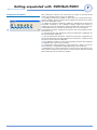
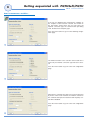
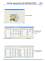
PQT H
SMART Modular network power
quality transducer
Instruction manual
Thank you for choosing our products
PQT H
SMART Modular network
power quality transducer
PQT H
• High accuracy (class 0.2 A/V);
• High calculation performances (ARM® technology) for a
fast analysis of the signal (FFT up to the 63rd harmonics);
• high connection capabilities (RS485 115.2 kbps, RS232,
ethernet port 10/100).
PQT H is the state-of-the-art tecnological answer to your
needs of power quality analysis and transducing.
Moreover, you can count on a ISO9001/VISION 2000
certified company structure, an experience of many years
and a wide-spread presence both in Europe and all over
the world. All this in order to guarantee the customer with
a top-quality service and the best products.
Welcome in Carlo Gavazzi and our compliments for your
choice. You can evaluate the complete range of our products on the CARLO GAVAZZI web-site:
www.carlogavazzi.com/ac
WM5-96
AL
Smart Power Quality Analyzer
Class 0.2 A/V
ARM R Powered
R
CARLO GAVAZZI
PRG
S
measures
Automation
!
Components
2
Index
PQT H
Instruction Manual
Introduction
. . . . . . . . . . . . . . . . . . . . . . . . . . . . . . . . . . . . . . . . . . . . . . . . . . . . .4
PQTHSoft Installation
Software Installation . . . . . . . . . . . . . . . . . . . . . . . . . . . . . . . . . . . . .5
Getting aquainted with PQTHSoft/PQTH
Front panel description . . . . . . . . . . . . . . . . . . . . . . . . . . . . . . . . . .7
Instantaneous variables measurements . . . . . . . . . . . . . . . . . . . . . .8
Configuration of automatic data reading . . . . . . . . . . . . . . . . . . .10
Manual data reading . . . . . . . . . . . . . . . . . . . . . . . . . . . . . . . . . . . .12
Configuration archive and remote PQT H programming . . . . . . .14
Dmd power calculation . . . . . . . . . . . . . . . . . . . . . . . . . . . . . . . . .18
Logging variables selection . . . . . . . . . . . . . . . . . . . . . . . . . . . . . .19
Tariffs . . . . . . . . . . . . . . . . . . . . . . . . . . . . . . . . . . . . . . . . . . . . . . .20
Digital outputs . . . . . . . . . . . . . . . . . . . . . . . . . . . . . . . . . . . . . . . .22
Alarm setup . . . . . . . . . . . . . . . . . . . . . . . . . . . . . . . . . . . . . . . . . .24
Logic and alarm parameters . . . . . . . . . . . . . . . . . . . . . . . . . . . . .25
Analog output . . . . . . . . . . . . . . . . . . . . . . . . . . . . . . . . . . . . . . . . .28
Example of analog output programming . . . . . . . . . . . . . . . . . . . .29
Serial port . . . . . . . . . . . . . . . . . . . . . . . . . . . . . . . . . . . . . . . . . . . .30
Internal clock setting . . . . . . . . . . . . . . . . . . . . . . . . . . . . . . . . . . .30
Reset . . . . . . . . . . . . . . . . . . . . . . . . . . . . . . . . . . . . . . . . . . . . . . .31
Configuration management . . . . . . . . . . . . . . . . . . . . . . . . . . . . . .32
Sending the configuration to the instrument . . . . . . . . . . . . . . . . .32
Re-configuring the instrument . . . . . . . . . . . . . . . . . . . . . . . . . . . .34
Reset of counters and events . . . . . . . . . . . . . . . . . . . . . . . . . . . .34
Printing settings . . . . . . . . . . . . . . . . . . . . . . . . . . . . . . . . . . . . . . .36
Configuration report (example) . . . . . . . . . . . . . . . . . . . . . . . . . . . .37
List of instruments in Ethernet . . . . . . . . . . . . . . . . . . . . . . . . . . . .38
Locking the access to programming and reset . . . . . . . . . . . . . .39
Lay-out and list of modules
Lay-out and list of modules . . . . . . . . . . . . . . . . . . . . . . . . . . . . . .40
Installation
Panel cut-outs . . . . . . . . . . . . . . . . . . . . . . . . . . . . . . . . . . . . . . . .41
Inserting, removing and mounting the modules to the panel . . . .41
DIN-rail mounting . . . . . . . . . . . . . . . . . . . . . . . . . . . . . . . . . . . . . .41
Sealing the instrument . . . . . . . . . . . . . . . . . . . . . . . . . . . . . . . . . .41
Index
PQT H Instruction Manual
3
Wiring diagrams
1 phase, 2-wire input connections . . . . . . . . . . . . . . . . . . . . . . . . .42
2-phase, 3-wire input connections . . . . . . . . . . . . . . . . . . . . . . . .42
3-phase, 3 and 4-wire input connections - balanced load . . . . . .42
3-phase, 3-wire input connections - unbalanced load . . . . . . . . .43
3-phase, 3-wire ARON input connections . . . . . . . . . . . . . . . . . . .43
3-phase, 4-wire input connections, unbalanced load . . . . . . . . . .43
Power supply, analogue and digital output modules . . . . . . . . . . .44
Digital inputs . . . . . . . . . . . . . . . . . . . . . . . . . . . . . . . . . . . . . . . . . .44
RS485 serial port . . . . . . . . . . . . . . . . . . . . . . . . . . . . . . . . . . . . . .44
Technical specifications
Input specifications . . . . . . . . . . . . . . . . . . . . . . . . . . . . . . . . . . . .45
Output specifications . . . . . . . . . . . . . . . . . . . . . . . . . . . . . . . . . . .46
Software functions . . . . . . . . . . . . . . . . . . . . . . . . . . . . . . . . . . . . .47
PqtHSoft . . . . . . . . . . . . . . . . . . . . . . . . . . . . . . . . . . . . . . . . . . . . .47
General specifications . . . . . . . . . . . . . . . . . . . . . . . . . . . . . . . . . .48
Power supply specifications . . . . . . . . . . . . . . . . . . . . . . . . . . . . .49
Revenue approval Settings . . . . . . . . . . . . . . . . . . . . . . . . . . . . . .49
Accuracy . . . . . . . . . . . . . . . . . . . . . . . . . . . . . . . . . . . . . . . . . . . . .49
Used calculation formulas . . . . . . . . . . . . . . . . . . . . . . . . . . . . . . .50
List of the variables that can be connected to . . . . . . . . . . . . . . .50
Insulation between inputs and outputs . . . . . . . . . . . . . . . . . . . . .51
4
Introduction
We suggest you to keep the original
packing in case it is necessary to
return the instrument to our Technical
Service Department. In order to
achieve the best results with your instrument,
we recommend you to read this instruction
manual carefully. If the instrument is used in a
manner not specified by the producer, the
protection provided by the instrument may be
impaired. Maintenance: to keep the instrument clean, use a slightly damp cloth; do not
use any abrasives or solvents. We recommend to disconnect the instrument before
cleaning it.
PQT H
Instruction Manual
This symbol indicates a particularly important subject or information.
This symbol indicates that more details are given
on the current subject.
This symbol indicates a suggestion for the user.
The images used in this manual are only useful to simplify the use of the instrument and
may not correspond exactly to reality.
PQT H philosophy, ARM® technology
PQT H is a brand new instrument with a high level of performances
and connection capability.
Actually, PQT H is a synergy of digital components that, coordinated
by an ARM® processor, allows the user to perform class 0.2 measurements for current and voltage, the management of 2 serial ports, 8
analogue outputs, 12 digital inputs, 16 alarms and a complete and
functional management of the energy meters tariffs. The ARM® based microprocessors are used in the up-to-date technology such as
the palmtop computers: this makes of PQT H a real computer at the
service of the electrical parameters analysis and of the electrical tariff
management, even the more complex one.
PQT H, thanks to its great flexibility,
allows to set in the menu (please
see the relevant section) also the
modules being installed in the base (holder
module). In order to simplify the modules, it is
advisable to take note of the identification
code (eg. AO2050) and the relevant installation slots (A, B, etc.): we suggest to fill in the
special module on the last page of this manual.
Programming PQTHSoft
PQT H Instruction Manual
Installation of PQTHSoft
5
Since PQTH is a transducer, it doesn’t have neither a display, nor a programming key-pad: for this reason a dedicated software is used (supplied with the
instrument) with the aim to program the instrument directly from the PC, display the measured variables and download the stored data.
Proceed as described below for the installation of the software: the installation
procedure will start automatically when the CD is inserted in the relevant drive
(the option of automatic start up of the CD reader must be active); window (01)
will be shown: choose the desired language and press OK, then follow the
instructions that will be displayed in the installation windows (02).
If the installation procedure will not start automatically, then explore the CD
and start manually the installation procedure by double clicking the
“setup.exe” icon.
Compatibility: Windows Vista, Windows XP, Windows 98x.
01
02
Getting acquainted with PQTHSoft/PQTH
PQT H Instruction Manual
Front panel description
01
01
02
03
04
05
06
07
7
After starting the software, the main frame (see figure on the left) will be
shown. The meaning of the icons is the following:
01) Reading instantaneous variables: it allows the user to read all the instantaneous variables, the max and min values logged in the instrument as well as
all the total and partial meters.
02) Setting up automatic monitoring: enables the download of the data of the
instrument according to the configured settings. When this function is
enabled, the main menu disappears and the program will continue to function
in the background, this function is indicated by an icon on the tool bar.
To disable the automatic reading and restore the main menu, double click on
the relevant icon.
03) Set up automatic data download: it allows the parameter configuration for
the automatic data download.
04) Set up manual data download: it allows the parameter configuration for
the manual download of the data logged in the instrument according to what
has been set in the relevant submenus.
05) Re-calibration: it allows to enter (after entering a protection password) the
re-calibration procedure of the instrument.
06) Configuration and programming of the instrument: it allows to enter the
next menu for the configuration and programming of the instrument.
07) Management of a list of instruments connected to the same ethernet network: it allows creating a list of instruments connected to an etherrnet network
with the allocation of the relevant IP address.
8
Getting acquainted with PQTHSoft/PQTH
PQT H
Instruction Manual
Read instantaneous variables...
If the icon for displaying the instantaneous variables on
the computer screen has been selected, the window on
the left will be shown where the user will select the
required connection type, the communication port being
used, the baud rate and parity type.
Press the “Next” button to go on to the following configuration page.
01
The window relevant to the selection of the baud rate is
active only if an RS485 connection type has been selected.
Press the “Next” button to go on to the next configuration
page.
02
When the PC communicates with one or more instruments
by means of the TCT/IP network, the windows relevant to
the communication port, the baud rate and the parity control will be disabled.
Press the “Next” button to go on to the next configuration
page.
03
Getting acquainted with PQTHSoft/PQTH
PQT H Instruction Manual
9
To enable the communication with the instruments,
press the “End” button.
04
The window on the left
shows how the computer screen displays
some instantaneous
variables.
05
The window on the left
shows how the computer screen displays the
energy meters.
06
10
Getting acquainted with PQTHSoft/PQTH
PQT H
Instruction Manual
Setup automatic data download...
If the icon relevant to the setup of the parameters for the automatic download of the data logged in the instrument has been selected, the following windows will appear:
This window allows the selection of the communication
type.
Press the “Next” button to go on to the following configuration page.
01
This window allows to select the type of download:
• Download of all energy meters from the instrument.
• Download of the events logged in the instrument (the
instrument will log all the alarms with relevant date and
time of activate/disactivate, plus all the max and min values of the selected variables).
For both the above selections, also the patch and the file
name under which the data are to be logged, must be
entered. It’s possible to choose either one or both selections.
Press the “Next” button to go on to the following configuration page.
02
03
This window allows the user to set the expiry date for automatic data download (daily, weekly, ... monthly).
If the “daily” option is selected, then it is possible to set a
customized time interval (for example every 10 days), setting the starting day, time interval and the time at which the
download is required to be started. It is moreover requested to select other options for the data download:
• Before automatic connection with PQTH request a confirm...: the software will ask the user to confirm the operation before the automatic connection to the instrument.
• If error, disable the automatic control... : if an error
occurs, the software will disable the data download of the
next expiry dates.
• Activate automatic control at once end this wizard: the
software will immediately activate the automatic control for
the data download at the end of this wizard.
Press the “Next” button to go on to the following configuration page.
Getting acquainted with PQTHSoft/PQTH
PQT H Instruction Manual
11
To end the Communication parameters setting, press the
“End” button.
04
12
Getting acquainted with PQTHSoft/PQTH
PQT H
Instruction Manual
Manual data download
If the icon for the configuration of the manual data download has been selected, the following windows will be shown subsequently:
Window for the communication setup (RS232, RS485 or
TCP/IP) with selection of the communication port (COM)
used by the computer, if present, baud rate and parity
type.
Press the “Next” button to go on to the next configuration
window.
01
This window allows the user to select which parameters
are to be downloaded (energy meters or logged event
download).
For both the above selections, also the patch and the file
name under which the data are to be logged, must be indicated. Since in this case, the computer does not manage
the data download automatically, the user must also tick if,
at the end of the download, the software is required to cancel the part of memory dedicated to the logging of the
events and/or if the max./min. peaks of logged events are
to be reset.
Press the “Next” button to go on to the next configuration
window.
02
To end the procedure, press the “End” button.
03
Getting acquainted with PQTHSoft/PQTH
PQT H Instruction Manual
13
While reading/downloading the data, the PC screen shows a graphic bar
illustrating the progress of the operation.
04
05
Getting acquainted with PQTHSoft/PQTH
14
PQT H
Instruction Manual
Configuration archive and remote PQT H
programming
If the icon relevant to the configuration archive and remote PQT H programming has been selected, the following windows will be
shown subsequently.
01
01
02
03
04
05
06
07
08
09
10
Windows for the configuration archive with the relevant
function icons:
1) It allows to get a configuration from a file.
2) It allows to export the configuration on a file, which can
be saved and then sent for example by email.
3) It allows the generation of a new configuration.
4) It allows the modification of a configuration present in
the archive.
5) It allows to delete a configuration from the archive.
6) It allows to send the instrument a configuration present
in the archive.
7) It allows a modification of the configuration of the instrument connected to the PC (the present configuration of the
instrument is shown and can be modified).
8) It allows to RESET all the logged data (more details on
page 34).
9) It allows the selected configuration to be printed.
10) It allows to define the printing configurations (more
details on page 36).
If the icon relevant to the setup for new configuration has been selected, the following windows will be shown subsequently.
Instrument composition: in the “Program name” text box,
it’s possible to name the configuration being created so as
to recognize it for any other necessary operations.
Since the instrument is not supplied with the automatic
detection function of the installed modules, these have to
be selected manually from the list available for each slot
(press the “drop down” box to enter the list of the modules
which can be installed for each slot).
Press the “Next” button to go on to the next configuration
window.
02
Getting acquainted with PQTHSoft/PQTH
PQT H Instruction Manual
15
This window allows the selection of the instrument’s main
programming data:
01
02
03
04
06
08
03
MSb
LSb
Tariff
off
off
1
off
on
2
on
off
3
on
on
4
1) It’s possible to define a protection password against
unintentional accesses to the programming data.
2) It’s possible to define a protection password against a
non-authorized downloading of the data.
05
3) Select the value of the primary/secondary ratio of the voltage transformer. Example: if the primary of the VT (voltage
transformer) connected to the instrument is 20kV and the
secondary is 100V, then the VT ratio corresponds to 200
07
(obtained carrying out the following calculation: 20000/100).
4) Select the value of the primary/secondary
ratio of the current transformer. Example: if the
primary of the CT (current transformer) being
09
connected to the instrument is equal to 300A
and the secondary is equal to 5A, then the CT
ratio corresponds to 60 (obtained carrying out
the following calculation: 300/5). Select the
value of the primary/secondary ratio of the current transformer. Example: if the
CT (current transformer) primary connected to the instrument is 300A and the
secondary is 5A, the CT ratio corresponds to 60 (obtained carrying out the following calculation: 300/5).
5) In this dropdown box it’s possible to define the standard to be applied in
the displaying of the instrument info pages: EN= European Standard, CAN=
Canadian Standard, ANSI= American Standard. Warning: this setting will also
affect the choice of the signal sampling frequency.
6) Here the user can define the type of system to which the instrument is connected (Single phase, 2-phase, 3-phase, ... ).
7) Define the working parameters of the digital filter (see examples on the following page).
8) Define how to use the tariff energy counter: from internal clock preceded by
programming of the single tariff inputs or by means of external commands.
9) It’s possible to assign to two digital inputs the “LSB” and “MSB” values representing the external commands with reference to the selection of the current
tariff. The energy meters divided by tariff are thus increased in a selective way
according to the status of the digital inputs (see figure “10”). These inputs are
to be connected to signals with an open or close logic status sent by the energy supplier and allowing the automatic selection of the current tariff. The
instrument has to know in advance the availability of the two AQ1042 and/or
AQ1038 modules in order to be able to manage these signals. The management of a single signal allows the management of two tariffs only.
Press the “next” button to go on to the next configuration window.
10
16
Getting acquainted with PQTHSoft/PQTH
PQT H
Instruction Manual
Programming the digital filter Examples
Example 1
It’s necessary to stabilize the value of the variable shown on thecomputer screen, that varies from 222V and 228V.
The parameters of the digital filter must be programmed as follows:
RANGE: the variable may have variations within the average amplitude value equal to ±0.75% of the rated value of the variable’s full
scale (calculated as follows: (228-222)/ 2= ±3V, and ±3*100/400V=
±0.75% where 400V is the rated value phase-neutral of an AV5 input).
The parameter “range”, that is the action range of the digital filter, will
be set at a value which is slightly higher than the percentage amplitude of the fluctuation: e.g. 1.0%.
COEFFICIENT: if the new value acquired by the instrument is within
the action range of the filter, the new displayed value is calculated by
summing (algebraically) to the previous value the variation divided by
the filtering coefficient. As a consequence, a higher value of this coefficient results in a higher settling time, that means a higher stability.
The best result is generally obtained by setting the filtering coefficient
at a value equal to at least 10 times the value of the range parameter.
In the example: 1.0*10= 10. To enhance the stability, you may also
increase the filtering coefficient (values within 1 and 32 only).
Example 2
It’s necessary to stabilize the value of the System Active Power
(W∑) shown by the computer screen, that varies from 300kW and
320kW (the load is connected to the instrument by means of a CT
300/5A and direct measurement of the voltage).
The parameters of the digital filter must be programmed as follows:
RANGE: the variable may have variations within the average amplitude equal to ±2.78% of the rated value of the variable’s full scale
(calculated as follows: (320-300)/ 2= ±10kW, and ±10*100/360kW=
±2.78% , where 360kW is the rated value of the active power of a system with AV5 input at the above mentioned conditions (CT ratio and
VT ratio) and obtained by the following formula: “VLN * VT * IN * CT *
3” where VLN = voltage of the rated input (400V for the input type
AV5), VT= primary/secondary ratio of the voltage transformer being
used, IN = rated current (5A for input type AV5), CT = primary/secondary ratio of the current transformer being used (in this example
“400*1*5*60*3=360kW).
The parameter “range”, that is the action range of the digital filter, will
be set at a value which is slightly higher than the percentage amplitude of the fluctuation: e.g. 3.0%.
COEFFICIENT: if the new value acquired by the instrument is within
the action range of the filter, the new displayed value is calculated by
summing (algebraically) to the previous value the variation divided by
the filtering coefficient. As a consequence, a higher value of this coefficient results in a higher settling time, that means a higher stability.
The best result is generally obtained by setting the filtering coefficient
at a value equal to at least 10 times the value of the range parameter.
In the given example: 3.0*10= 30. To enhance the stability, you may
also increase the filtering coefficient (values within 1 and 32 only).
Getting acquainted with PQTHSoft/PQTH
PQT H Instruction Manual
17
Example 3.
It’s necessary to stabilize the value of the AL1 variable (phase 1
current) shown on the computer screen, that varies from 470V and
486V.
In order to manage the alarm function as best as possible, thus
enabling and disabling the relay, this value must not be subject to
continuous variations. In this example a 500/5A current transformer
has been used. The parameters of the digital filter must be programmed as follows:
RANGE: the variable may have variations within the average amplitude value equal to ±1.60% of the rated value of the variable’s full
scale (calculated as follows: (486-470)/ 2= ±8A, and ±8*100/500V=
±1.60% where 500A is the rated value referred to the transformer
being used). The parameter “range”, that is the action range of the
digital filter, will be set at a value which is slightly higher than the percentage amplitude of the fluctuation: e.g. 2.0%.
COEFFICIENT: if the new value acquired by the instrument is within
the action range of the filter, the new displayed value is calculated by
summing (algebraically) to the previous value the variation divided by
the filtering coefficient. As a consequence, a higher value of this coefficient results in a higher settling time, that means a higher stability.
The best result is generally obtained by setting the filtering coefficient
at a value equal to at least 10 times the value of the range parameter.
In the example: 2.0*10= 20. To enhance the stability, you may also
increase the filtering coefficient (values within 1 and 32 only).
18
Getting acquainted with PQTHSoft/PQTH
PQT H
Dmd power calculation setup
In this window it’s possible to define which must be the method to be used for
the calculation of the average power:
01
02
03
Instruction Manual
04
04
Fixed/sliding selection
1) FIXED or SLIDING (see explanation below).
2) Enter the integration time relating to the DMD average
calculation (DMD).
3) Indicate the method to be used by the instrument for the
synchronisation of the integration period for the calculation
of the “DMD” variables:
• NONE: the instrument starts the counting relating to the
integration time at the switching on of the instrument itself
and updates its values with the intervals defined at the previous point.
• INTERNAL CLOCK: the calculation for the integration of
the DMD variables will start at the end of the first exact
hour following the switching on of the instrument itself
(example: if the instrument is switched on at 10.35, the calculation of the DMD values will start at 11.00) and the
instrument will update the values with the intervals defined
at point “2”.
4) EXTERNAL CONTACT: the calculation for the integration
of the DMD variables will start as soon as the instrument receives a pulse from
an external command (by means of a digital input defined in windows n. 4);
the instrument will update the values with the intervals defined at point “2”.
Every further pulse received from the instrument, will cause a re-synchronisation of the counting for the integration period.
Press the “Next” button to go on to the following configuration window.
FIXED SELECTION: if for example a time interval
of 15 minutes has been selected, the instrument
calculates the dmd value of the measured variable
and updates its value every 15 minutes.
Where:
Pmax is the maximum power,
Pc is the contractual power,
t1 is the time period selected for the calculation of the
dmd value
SLIDING SELECTION: if for example you have
selected a time interval of 15 minutes, the instrument calculates the dmd value and updates it after
the first 15 minutes, and then every minute, generating a 15-minute wide window moving onwards
every 1 minute.
Getting acquainted with PQTHSoft/PQTH
PQT H Instruction Manual
19
Set events logging...
In this window it’s possible to select which events are to be
selected and logged in the instrument (the instrument is
able to log up to 10000 events). Referring to the variables,
it’s possible to log up to 3 kind of events: MIN events /
MAX events and DMD MAX events.
05
With reference to the digital inputs/outputs, it’s possible to
log any modification of the status, no matter what their
function is (remote, synchronisation or tariff change).
05
With reference to the alarms and/or reset commands, the
logging of all the above mentioned events includes date
and time relevant to the event itself.
Press the “Next” key to go on to the next configuration
page.
05
20
Getting acquainted with PQTHSoft/PQTH
PQT H
Instruction Manual
Tariff
In this window it’s possible to set the desired tariff
indicating for each day of the week if it is to be considered as a Working day or as a Holiday.
Press the “Next” button to go on to the following configuration window.
06
For each tariff type the user will have to define: start hour, end hour
and relevant start and end dates of each period. Also the tariff type to
be coupled to the above mentioned period is to be indicated.
Press the “OK” button to confirm.
07
The following operations are available:
• ADD : it allows the user to create a new tariff.
• INSERT : it allows the user to insert a new tariff in
a well defined position.
• EDIT : it allows the modification of a previously
inserted tariff.
• DELETE : it allows to delete the selected tariff.
• DELETE ALL : it allows to delete the configuration
of the previously inserted tariffs.
Press the “Next” button to go on to the following
configuration window.
08
Getting acquainted with PQTHSoft/PQTH
PQT H Instruction Manual
21
Example of tariff programming
Eg.: the energy supplyer company sets the following tariffs for
December: the working week starts from Monday to Friday and the
Weekend includes Saturday and Sunday. In the working days there are
two different tariffs: from 8 am to 5 pm in tariff “T4” and from 5 pm to
8 am in tariff “t3”; in the weekends there is a single tariff “T2”.
Step one: programme the standard week.
The working days will be indicated as follows:
Monday (W), Tuesday (W), Wednesday (W), Thursday (W), Friday (W).
The holidays will be indicated as follows:
Saturday (H), Sunday (H).
Step two: programme the rows displaying the tariffs division for the
working days:
In the tariff table there are
max. 100 rows to be selected.
First row: Start hour = 00, End hour = 8, Start date = 01/12, End date
= 31/12, then select “Working” and Tariff “3”.
Second row: Start hour = 8, End hour = 17, Start date = 01/12, End
date = 31/12, then select “Working” and Tariff “4”.
Third row: Start hour = 17, End hour = 24, Start date = 01/12, End
date = 31/12, then select “Working” and Tariff “3”.
The fourth row will identify the holidays other than Saturday and
Sunday (for example December 25th and 26th).
Fourth row: Start hour = 00, End hour = 24, Start date = 25/12, End
date = 26/12, then select “Holidays” and Tariff “2”.
The tariffs have thus been programmed and the instrument will display
the window shown below.
Since the tariffs above programmed refer only to the month of
December, it is necessary to set a tariff referring to the rest of the year,
named “T1”.
In this case, the pre-set tariff is to be used, and it is to be set to “1”:
the instrument will thus automatically use the “T1” tariff when there are
no other programmings.
22
Getting acquainted with PQTHSoft/PQTH
PQT H
Instruction Manual
This window allows to define the function of each
single digital output present in the instrument (if
installed). Each function can be selected as:
• PULSES: to retransmit the energy by means of digital pulses; in this case the user is required to indicate the energy type to be coupled to this output
(imported or exported energy, active or reactive
energy, total or partial energy) and the pulse output
value (the number of Wh for each single pulse).
09
• ALARMS: the digital output will be energized
and/or de-energized according to the alarm status to
which the output is connected. The output normal
status (normally energized or normally de-energized)
is also to be defined.
Press the “Next” button to go on to the following
configuration window.
09
Getting acquainted with PQTHSoft/PQTH
PQT H Instruction Manual
The digital outputs shown in the below
table (see yellow boxes only) are submitted to a short self test when the
instrument is switched on, and are thus energized for a short period. They’re therefore not
recommended to be used as pulse outputs.
Code
Description
AO1058
1 relay output
Slot A
Slot B
Slot C
Slot D
A0
B0
C0
D0
1 open coll. output A0
B0
C0
D0
A0 A1
B0 B1
C0 C1
D0 D1
AO1036
2 open coll. outputs A0 A1
B0 B1
C0 C1
D0 D1
AO1037
4 open coll. outputs A1 A2 A3 A4 B1 B2 B3 B4 C1 C2 C3 C4 D1 D2 D3 D4
AO1059
AO1035
2 relay outputs
23
24
Getting acquainted with PQTHSoft/PQTH
PQT H
Instruction Manual
Alarm set up
01
02
03
04
05
06
07
08
10
This window allows the user to set all the alarms. The
instrument can manage up to 16 alarms which can be connected to the digital outputs present in the instrument
either one-to-one (1 output = 1 alarm) or by groups using
the “OR” or “AND” logic function. The programming of
each alarm is to be carried out as follows (the numbers
refer to the figure on the left):
09
1) Selection of the variable to be controlled.
2) Definition of the variable’s multiplying factor to be controlled and the position of the decimal point.
10
3) Set-up of set-point 1.
4) Set-up of set-point 2.
11
5) Set-up of a delay time in seconds relevant to the activation of the alarm starting when a condition of the variable
requiring the activation of the alarm occurs.
12
6) Set-up of a delay time in seconds relevant to the disactivation of the alarm occurring when the variable exits from
the alarm condition.
7) Connection of the alarm to a specific digital output
(more than one alarm can be connected to the same digital output).
8) Define the alarm type:
• Up-alarm with hysteresis
• Down-alarm with hysteresis
• In-window alarm
• Out-window alarm
9) Enable or disable each single alarm.
10) Enable or disable the latch function, if enabled, when the alarm is deactivated (the deactivation of the alarm is automatic). If this function is enabled,
to disable the alarm condition a manual reset command will be required.
11) Defines the logic function to which the alarm has to answer (see example
on the following page).
12) Defines the alarm status at the switching on of the instrument: if the function is active, the first alarm condition monitored by the instrument will be
ignored and the alarm will not be activated.
Press the “Next” button to go on to the following configuration window.
Getting acquainted with PQTHSoft/PQTH
25
PQT H Instruction Manual
Alarm logic and parameters
Each symbol includes all
the settings described in
the “alarm” paragraph and
listed on the right:
ON alarm (SET 1)
- Activation
- Variable
- Alarm type
- Latch
- Deactivation
- Set point 1
- Set point 2
- Output
- Activation delay Deactivation delay
- Function (AND/OR)
8
Alarm in 1 (SET 1)
OFF alarm (SET 1)
A, B, C... up to 16 blocks of
parameters control.
Alarm Out 1 (SET 1)
Alarm in 2 (SET 2)
(SET 2)
ON alarm (SET 2)
OFF alarm (SET 2)
Activation of the alarm function
UP alarm
SET 1 > SET 2
Out window alarm with disabling at power on
In alarm over SET 1 and
below SET 2
In-window Alarm
In alarm between
SET 1 and SET 2
DOWN alarm
SET 2 < SET 1
Examples of AND/OR logic alarms:
AND
A: AND
A: AND
A: AND
B: AND
B: AND
B: AND
C: AND
C: AND
C: AND
A: OR
OR
OR+AND
A: OR
B: OR
B: OR
C: OR
C: AND
A: OR
A: OR
B: OR
B: OR
C: OR
C: AND
A: OR
A: OR
B: OR
B: OR
C: OR
C: AND
D: AND
D: AND
D: AND
Getting acquainted with PQTHSoft/PQTH
26
PQT H
Programming examples of the alarm
parameters.
235V
215V
Activation
300kW
295kW
We recommend to delay of a few seconds the
alarm deactivation in order to avoid
the swinging effect of the output
and therefore the possible damage
of the contact due to fluctuations of the measured signal with a value near the selected
alarm set points.
Instruction Manual
Activation of an alarm when the network voltage VL1-N is outside the
window 215V – 235VAC.
Select the out-window alarm so that the output is activated when
exceeding 235V and going below 215V.
The recommended programming is as follows:
- Activation of one of the 16 alarms (example alarm 01 ON)
- Select the variable to be controlled: VL1-N= V1
- Select the desired type of alarm: OUT
- Select if enabling or not the latch: OFF
- Select if enabling or not the deactivation of the first alarm status
starting from the switching on of the instrument: ON
- Set set-point 1 = 235V
- Set set-point 2 = 215V
- Select to which digital output the alarm being programmed is to be
addressed to (the digital output must have been previously enabled to
the “alarm” function; in the same menu, the user can select the
required type of output: “ND or NE”).
- If a delay on activation is required, set the number of seconds: e.g.
“5 seconds”.
- If a delay on deactivation is required, set the number of seconds: e.g.
“5 seconds”.
- Select the type of logic with which the alarm is to be managed: “OR”
(see example: AND/OR logic alarm).
Disconnection of a load when exceeding a predefined value of consumed power: for example, when exceeding 300kW, the alarm has to
be activated and disconnect a predefined load. An “UP” alarm is
selected. The recommended programming is as follows:
- Activation of one of the 16 alarms (example alarm 02 ON)
- Select the variable to be controlled: W system (W∑)
- Select the desired type of alarm: “UP”
- Select if enabling or not the latch: “OFF”
- Select if enabling or not the deactivation of the first alarm status
starting from the switching on of the instrument: “OFF”
- Set set-point 1 = 300kW
- Set set-point 2 = 295kW
- Select to which digital output the alarm being programmed is to be
addressed to (the digital output must have been previously enabled to
the “alarm” function; in the same menu, the user can select the
required type of output: “ND or NE”).
- If a delay on activation is required, set the number of seconds: e.g.
“5 seconds”.
- If a delay on deactivation is required, set the number of seconds: e.g.
“5 seconds”.
- Select the type of logic with which the alarm is to be managed: “OR”
(see example: AND/OR logic alarm).
Getting acquainted with PQTHSoft/PQTH
PQT H Instruction Manual
27
The instrument is able to manage two types of alarms: real
alarm = when the alarm is connected to a digital output (relay
output or open collector output). The activation of a real alarm
causes the switching on at fixed light of the “AL” LED on the
front of the instrument. Virtual alarm = when the alarm is not connected to any output. The activation of a virtual alarm causes the switching on at flashing light of the “AL” LED. In case of coincidence of a
virtual alarm and of a real alarm, the real one has the prevalence over
the control of the above mentioned LED (therefore it switches on at
steady light). By exploiting the AND and OR functions, it’s possible to
connect together more than one virtual alarms and send them to a single digital output (relay output or open collector output). In any case
the max limit of programmable alarms is 16.
Alarm 01
Alarm 02
The drawing above explains how the alarms in the example
work. Since the “OR” function has been selected for both the
alarms, the working of the digital output can be represented by
two contacts in parallel. The activation of one of the two alarms
is sufficient to activate the digital output.
28
Getting acquainted with PQTHSoft/PQTH
PQT H
Instruction Manual
Analog output
02
04
06
11
This window allows the user to set the parameters relevant
to the single analogue outputs:
1) Allows the user to select the variable to be retransmitted
by means of an analogue output.
2) Allows the user to define the variable’s multiplying factor and the decimal point position.
3) Allows the user to set the max. value of the variable to
01
be retransmitted. This value will be connected to the max
value of the analogue output.
4) Allows the user to set the minimum value of the variable
03
to be retransmitted. This value will be connected to the
min. value of the analogue output.
5) Allows the user to set the value expressed as % of the
05
full scale of the output range (20mA, 10V, etc.) that will be
generated in correspondence with the max. input value set
above.
6) Allows the user to set the value expressed as % of the
full scale of the output range (20mA, 10V, etc.) that will be
generated in correspondence with the min. input value set above.
NOTE : in the measuring range defined at N. “3” and “4”, the instrument will
see that the linearization of the output signal (20mA, 10V, etc) from the min.
value defined at N. “6” to the max. value defined at N. “5”.
Press the “Next” button to go on to the following configuration window.
The instrument manages the following
combinations of analogue outputs:
max. N. 8 outputs 0-10VDC; Max N. 8
outputs -5/+5mADC. Any combination of the
two above mentioned types considering that
every module manages 2 outputs. Max n. 4
outputs 0/20mADC. Max n. 4 outputs
0/20mADC + max n.4 outputs 0-10VDC.
Getting acquainted with PQTHSoft/PQTH
PQT H Instruction Manual
29
Programming examples of the analogue outputs
Retransmission of the power by means of a 0-20mA analogue output.
To measure a consumed power up to 100kW and retransmit this value
by means of a signal from 4 to 20 mA: the module to be used is
AO2050 (2x from 0 to 20mA); the instrument is to be programmed as
follows:
VARIABLE: W∑ (system active power).
MIN VAL OUT: 20.0% for 4mA, calculated as follows: (100*min output)/ fullscale output = 100*4mA/20mA=20%.
MAX VAL OUT: 100.0% for 20mA, calculated as follows: (100*max.
out)/ fullscale output= 100*20mA/20mA= 100.
MIN VAL INP: 0.0k; the multiples k,M,G can be selected on the instrument according to the VT and CT values being selected.
MAX VAL INP: 100.0k; the multiples k,M,G can be selected on the
instrument according to the VT and CT values being selected.
Retransmission of the consumed and generated active power by
means of a -5/+5mA analogue output.
Measure both the consumed active power up to 100kW and the generated power up to -100kW and retransmit this value by means of a
signal from -5 to +5 mA: the module to be used is AO2052 (2x from
-5/+5mA), the instrument is to be programmed as follows:
VARIABLE: W∑ (system active power).
MIN VAL OUT: -100% for -5mA, calculated as follows: (100*min output)/ fullscale output= 100*5mA/-5mA=-100%.
MAX VAL OUT: 100.0% for 20mA, calculated as follows: (100*max
output)/ fullscale output= 100*5mA/5mA= +100%.
MIN VAL INP: -100.0k; the multiples k,M,G can be selected on the
instrument according to the VT and CT values being selected.
MAX VAL INP: 100.0k; the multiples k,M,G can be selected on the
instrument according to the VT and CT values being selected.
ϕ) by means of anaRetransmission of the POWER FACTOR (cosϕ
logue output 0-20mA.
Retransmit the whole range of the values admitted for the PF(cosϕ)
with signal from 0 to 20mA. The max. attention must be paid because
the values of the PF variable (cosϕ) can be included between C0.001
and L0.000 (for each phase) that after retransmission will have the values included between 0 and 20mA. When the PF (cosϕ) has a value
equal to 1 being included exactly in the middle between C0.001 and
L0.000, the output will have the value of the middle of the scale, that
is 10mA. As a consequence, the instrument is to be programmed as
follows:
VARIABLE: PF L1 (or L2 or L3 or PF∑).
MIN VAL OUT: 0.0%.
MAX VAL OUT: 100.0%.
MIN VAL INP: C0.001 (the symbol C shows that the value is CAPACITIVE).
MAX VAL INP: L0.001 (the L symbol shows that the value is INDUCTIVE). The min. value which can be set is L0.001 in order to avoid
undesired fluctuations of the analogue outputs.
Getting acquainted with PQTHSoft/PQTH
30
PQT H
Instruction Manual
The serial output setup
In this window it’s possible to set the parameters of the
serial output.
NOTE: if you are using the RS485 module code AR034,
the max baud-rate value which can be set is 9600. If the
AR2040 module is used, then the max baud-rate value is
115200.
Press the “Next” button to go on to the following configuration window.
12
Clock setup...
03
01
04
02
13
05
In this window it’s possible to set the parameters relating
to the internal clock:
1) Clock usage:
• NOT USED: the instrument will not be able to manage
any function requiring the clock; no information on date
and time will be available.
• USED WITHOUT BACKUP: at every new switching of the
instrument, the setting of the complete date and hour will
be required.
• USED WITH BACKUP: once date and hour will be set,
the instrument will keep date and hour updated also in
case of switching off of the instrument itself.
NOTE: in order to select this option, the AR1039 module
must be installed in the instrument.
2) Allows the user to set the geographic area where the
instrument is installed.
3) Allows the user to decide if synchronizing date and time of the instrument
with the date and time of the PC, at the end of the programming, or not.
Press the “Next” button to go on to the following configuration window.
Getting acquainted with PQTHSoft/PQTH
PQT H Instruction Manual
31
Reset
This window allows the user to select which reset commands are to be carried out automatically at the end of the
programming procedure.
Press the “Next” button to go on to the following configuration window.
14
To complete the configuration setup, press the “End” button.
NOTE: For each one of the previously described windows,
the CANCEL button allows the user to cancel all the settings made until that moment: the starting window will then
appear on the screen. Pressing the BACK button, the user
goes back to the previous page.
15
32
Getting acquainted with PQTHSoft/PQTH
PQT H
Instruction Manual
Configuration archive
At this stage, the user is required to select the configuration to be transmitted to the instrument and enable the
transmission procedure clicking the icon shown in figure
(1).
01
01
Transmitting the configuration to the
instrument (remote configuration)
01
04
02
05
03
02
This window allows the user to define the parameters for
the serial communication by which the configuration is to
be transmitted:
1) Select the mode and type of the connection used
between PC and instrument.
2) Select the password allowing the access to the programming of the instrument (default value is 0).
3) Select the communication port used by the PC.
4) In case of RS485 serial communication, select the baudrate value.
5) Select the parity. Should this value not be known, the
user may set “Automatic detection”: in this case the software will search automatically which is the value set on the
instrument.
Press the “Next” button to go on to the following configuration window.
Getting acquainted with PQTHSoft/PQTH
PQT H Instruction Manual
33
To start the programming of the instrument, press the
“END” button.
03
During the programming phase of the instrument, a graphic bar will show its
progress, step by step. When the bar is full, the programming has finished.
03
During the download, the software will show both the progress on the graphic bar and some data relating to the instrument, such as network address and
serial number.
03
34
Getting acquainted with PQTHSoft/PQTH
PQT H
Instruction Manual
Change instrument setput...
From the main window of the PQTSoft, clicking the icon
shown on the left of figure 1, it’s possible to change the
programming of the instrument by displaying on the PC its
present configuration and thus allowing the user to modify
the parameters. Before displaying the configuration, the
software asks the user to select which are the modules
installed in the instrument since the software cannot identify them.
Proceed with the setup changing procedure, following the
same instructions given on page 14, number (2).
01
Reset
From the main window of the software, clicking the icon on
the left of figure 01 (RESET), the user can start the reset
procedure of the meters and/or events. In this window, the
user selects the communication modes (RS485, RS232,
etc.) and the relevant parameters (password, communication port, baud rate and parity).
Press the “Next” button to go on to the following configuration window.
01
Getting acquainted with PQTHSoft/PQTH
PQT H Instruction Manual
35
This window allows the user to select the RESET COMMANDS to be carried out.
Press the “Next” button to go on to the following configuration window.
02
Press the END button to start the RESET procedure.
02
Getting acquainted with PQTHSoft/PQTH
36
PQT H
Instruction Manual
Printing Setup
From the main window of the software, clicking the icon on
the top left of figure 1, the user enters the setup procedure
of the printing options relating to the “List of the instruments
configuration parameters” where all the data set on the
instrument are listed (see example on the following page):
01
02
03
1) Type the name of the image file (bitmap or jpeg) to be printed as heading of the page itself. The dimension of the image
cannot exceed 790 pixel width and 180 pixel height
2) To add bottom page notes, tick box N. 2 on the left and type
on the two below boxes the required text.
3) To print the numbering of the pages tick the box “Printing
numbering of the pages”.
01
Press the “OK” button to confirm the set values.
Getting acquainted with PQTHSoft/PQTH
PQT H Instruction Manual
Configuration report (example)
Modello strumento:
Note:
______________________________________________________________________________
_________________________________________________________________________________________
ELENCO DEI PARAMETRI DI CONFIGURAZIONE DELLO STRUMENTO
DENOMINAZIONE PARAMETRO
VALORE PARAMETRO
Nome programma
Configurazione 1
Slot A
Modulo AO1037
Slot B
Modulo AR2040
Slot C
Modulo AQ1038
Slot D
Modulo AQ1038
Slot E
Modulo AR1039
Slot IM
Modulo AQ2030
Password config.
0
Password scarico dati
0
Info contatore
EN
Rapporto TV
0,100
Rapporto TA
0,100
Sistema
Monofase
Campo di intervento del filtro
0,1%
Coefficiente di filtraggio
1
Gestione contatori energia di tariffa
Con impulsi dal fornitore di energia
Ingresso tariffa LSB
DigInC1
Ingresso tariffa MSB
DigInD2
Calcolo potenza media (Metodo di integrazione)
Fissa
Calcolo potenza media (Tempo di integrazione)
15 minuti.
Sincronizzazione
Contatto esterno (DigInC3)
Eventi MIN
VA L1 min.
Eventi MIN
Hz min.
Eventi MAX
W L1 max.
Eventi MAX
var L1 max.
Eventi DMD MAX
THDo VL1-N dmd max.
Eventi DMD MAX
THDe VL1-N dmd max.
Eventi allarme
Allarme04
Eventi allarme
Allarme06
Eventi comandi azzeramento
Contatori totali energia importata
Eventi comandi azzeramento
Contatori parziali energia importata
37
Getting acquainted with PQTHSoft/PQTH
38
PQT H
Instruction Manual
List of the instruments connected to an Ethernet network
From the main window of the software, clicking the icon
indicated on the top left of the figure on the left, the user
enters the new window where all the ethernet addresses of
the instruments connected to the same network are
shown.
Clicking on the “New Instrument” button, you enter the
window allowing the user to type the data of a new instrument.
01
01
02
03
1) Each instrument must be given a name so that it can be identified
2) Set the relevant IP address
3) Set the MODBUS TCP/IP port
4) Type the data file folder including the files of the meters, of the events
and the data of the instrument.
5) Tick this box if the instrument is on line.
NOTE: for the data at N. 2 and 3, it is recommended to contact the network administrator.
04
05
02
Clicking the “Modify Instrument” button, the user may modify the data
relating to N. 1 to 5 of the selected instrument.
Clicking the DELETE INSTRUMENT button, the selected instrument can be
modified.
Press the OK button to end the procedure.
03
Getting acquainted with PQTHSoft/PQTH
PQT H Instruction Manual
39
Locking access to programming and
reset
a
Turning the relevant trimmer with a screw driver, up to end-stroke and
anticlockwise (see drawing on the left (a)), the access to the programming of the instrument is locked from the serial port. Moreover, the
RESET commands cannot be executed any longer. However, it will still
be possible to scroll all the display pages and the relevant details.
40
Lay-out and list of modules
PQT H
PQT H
Description
Ch
Code
Legend
AD2020
PQT H
AQ2030
AQ2031
AV5.3
AV6.3
AP1021
AP1020
L
H
XX
E2
D1
D2
O4
O2
O1
R1
B1
W1
B2
Instruction Manual
AV53 H XX XX XX XX XX
Model
PQT H base
Measuring inputs
400/690VL-L 1/5A (10A)
120/208VL-L 1/5A (10A)
3
3
4
2
1
1
2
2
2
1
1
AQ1038
AQ1042
AO1037
AO1036
AO1059
AO1058
AO2050
AO2051
AO2052
AR1034
AR2040
None
Digital inputs
Digital inputs + aux
Open collector output
Open collector output
Open collector output
Relay output
Relay output
Analogue output 10VDC
Analogue output +/-5mA
3
3
4
2
1
1
2
2
2
AQ1038
AQ1042
AO1037
AO1036
AO1059
AO1058
AO1035
AO2051
AO2052
None
Digital inputs
Digital inputs + aux
Open collector output
Open collector output
Open collector output
Relay output
Relay output
Analogue output 10VDC
Analogue output +/-5mA
3
3
4
2
1
1
2
2
2
AQ1038
AQ1042
AO1037
AO1036
AO1059
AO1058
AO1035
AO2051
AO2052
Non-certified measures
1
RS232 + RTC (Non certified measures)
Certified measures: a “device document” has to be filled in by the user.
RS232 + RTC + option “XU”
1
AR1039
AR1039
B
XX
D1
D2
O4
O2
O1
R1
B1
W1
B2
S1
S2
C
XX
D1
D2
O4
O2
O1
R1
R2
W1
xx
D
XX
D1
D2
O4
O2
O1
R1
R2
W1
B2
SLOT
None
Digital inputs
Digital inputs + aux
Open collector output
Open collector output
Open collector output
Relay output
Analogue output 20mADC
Analogue output 10VDC
Analogue output +/-5mA
RS485 9600bps
RS485 115200bps
A
SLOT
AR1061
AQ1038
AQ1042
AO1037
AO1036
AO1059
AO1058
AO2050
AO2051
AO2052
SLOT
1
3
3
4
2
1
1
2
2
2
SLOT
None
Ethernet/Internet port
Digital inputs
Digital inputs + aux
Open collector output
Open collector output
Open collector output
Relay output
Analogue output 20mADC
Analogue output 10VDC
Analogue output +/-5mA
OPTIONS
Power supply 18-60VAC/DC
Power supply 90-260VAC/DC
SLOT
Power supply
E
XX
SX
XU
SU
Code example:
PQT-H AV53 H B1 S1 R2 O2 SX
Material
PQT-H
AV53 measuring inputs (400/690VL-L)
90-260VAC/DC power supply
Analog output 20mA (2 channels)
Serial port RS485 at 9600 bps
Relay output (2 channels)
Open collector output (2 channels)
Serial port RS232+RTC
A
B
Code
AD2020
AQ2030
AP1020
AO2050
AR1034
AO1035
AO1036
AR1039
C
D
E
Measuring
inputs
Power Supply
Installation
PQT H Instruction Manual
41
90
Dimensions and panel cutout
90
Inserting, removing and mounting the modules to the panel
2 Extract the central blind module, so that all the
other modules are free.
3 Extract the blind modules and
replace them where necessary
with the plug and play modules.
1
1 Disconnect the central module
acting on the anchor tabs with a
suitable flat screw-driver.
2
3
4 The last module to be inserted
will be the central one having
also the function to lock all the
other modules.
Make sure that the modules supplied DIN-rail mounting
with the instrument are inserted in the
correct slot as shown by the stickers
placed on the modules themselves and as
described in the table on the right.
If the instructions are not followed carefully, the
instrument may be damaged. The plug and
play modules are only to be inserted and
extracted when the instrument is not connected to the mains and when the measuring
inputs are disconnected. Before connecting
the power supply of the instrument to the network, make sure that the power supply voltage
corresponds to the data shown on the label of
the power suppply module.
Sigillatura dello strumento
The relevant sealing kit is supplied together with the instrument. It is made
by two wedge-shaped plastic devices (a) that will have to be inserted as
shown by figure (b); then place the seal as indicated by figure (c).
a
b
c
Wiring diagrams
42
PQT H
Instruction Manual
1-phase, 2-wire input connections (1P)
Fig. 1
8
7
1
2
Fig. 2
Fig. 3
9 10
L1
N
Direct connection
CT and VT connection
CT connection
2-phase, 3-wire input connections (2P)
Fig. 4
8
7
9
1
2
3
Fig. 5
4
I
L1
L2
1
3
5
L1
L2
L3
2
4
6
1
3
5
2
4
6
8
L1
8
7
N
10
L3
L2
9
U
7
10
N
9
CT connection
Direct connection
3-phase, 3 and 4-wire input connections, balanced load (3P)
Fig. 6
8
9
10
1
Fig. 7
Fig. 8
2
L1
L2
L3
Direct connection (3-wire system)
CT and VT connection (3-wire system)
CT and VT connection
(4-wire connection)
Wiring diagrams
43
PQT H Instruction Manual
3-phase, 3-wire input connections, unbalanced load (3P)
Fig. 9
8
9
10
1
2
3
4
5
Fig. 11
Fig. 10
6
L1
L2
L3
Direct connection (3-wire system)
CT and VT connection (3-wire system)
CT connection (3-wire system)
3-phase, 3-wire ARON input connections, unbalanced load (3P)
Fig. 12
Fig. 13
I
ARON connection (3-wire system)
1
3
5
L1
L2
L3
2
4
6
1
3
5
2
4
6
8
L1
8
7
N
10
L3
L2
9
U
7
10
9
ARON and VT connection (3-wire system)
3-phase, 4-wire, unbalanced load input connections (3P+N)
Fig. 14
8
9
10
7
1
2
3
4
5
Fig. 15
Fig. 16
6
L1
L2
L3
N
Direct connection (4-wire system)
CT connection (4-wire system)
CT and VT connection (4-wire system)
Wiring diagrams
44
PQT H
Instruction Manual
Power supply, analogue and digital output modules
AP1020.
AP1021.
Power supply
A2
A1
F
F= 1,25 A T
N
-
L
+
AO2050.
2 analogue outputs
0-20mA DC.
AO1058.
1 relay output
AO2052.
2 analogue outputs
-5/+5mA DC.
AO2051.
2 analogue outputs
10V DC.
AO1037. 4 open collector outputs. This drawing
is also valid for the open collector modules with
less outputs. The load resistances (Rc) must be
designed so that the close contact current is
lower than 100mA; the VDC voltage must be
lower than or equal to 30VDC.
AO1035.
2 relay outputs
Digital inputs
AQ1042.
NPN transistor type connection.
AQ1042.
NPN transistor type connection.
AQ1042.
Contact connection
AQ1038.
Contact connection
T
a
SERIAL TRANSDUCER
RS485 Serial Port (AR1034 9600bps, AR2040 115200bps)
b
2-wire connection. Some more WM5-96 (a) provided with RS485 are
connected in parallel. (b) RS485-RS232 serial transducer.
T
a
SERIAL TRANSDUCER
Serial port termination (T): it is carried out only on the last instrument
of the network, by means of a jumper between (Rx+) and (T).
b
4-wire connection. Some more WM5-96 (a) provided with RS485 are
connected in parallel. (b) Serial transducer RS485-RS232.
Serial port termination (T): it is carried out only on the last instrument of the network, by means of a jumper between (Rx+) and (T).
TECHNICAL SPECIFICATIONS
PQT H Instruction Manual
45
Input specifications
Number of analogue inputs
Current
Voltage
Digital inputs (on request)
AQ1038
Purpose
Contact measuring current
AQ1042
Purpose
Excitation output
Contact measuring current
Common characteristics
Close contact resistance
Open contact resistance
Insulation
Reactive power
1 (1-phase; system code: 3)
3 (3-phase; system code: 3)
1 (1-phase; system code: 3)
4 (3-phase; system code: 3)
Up to 12
No. of inputs: 3 (voltage-free)
“dmd” measurements
synchronisation.
Tariff selection: energy.
Contact status reading.
Clock synchronisation.
<8mA/ 17.5 a 25VDC
Number of inputs: 3 +
excitation output
“dmd” measurements
synchronisation.
Tariff selection: energy.
Contact status reading.
Clock synchronisation.
16V<+Aux<24VDC Max 15mA
15mA
Max 1kΩ
Min 100kΩ
see “Insulation between
inputs and outputs” table
Accuracy (display, RS232, RS485) In: 5A, If.s.: 10A
Un: see voltage ranges below
Current (AL1, AL2, AL3)
from 0.05In to Imax:
(@20°C ±5°C, H.R. ≤75%)
±(0.2%RDG+2DGT) from
0.01In to 0.05In:
±(0.5%RDG+2DGT)
±0.5% RDG (0.2 to 2 In)
Current (An)
from 40 to 100 Hz
Voltage (@20°C±5°C, R.H.≤75%)
range AV5:
400/690VL-L AC
VL-N: from 185 V to 460 V
VL-L: from 320 V to 800 V
±(0.2%RDG+1DGT)
range AV6:
120/208VL-L AC
VL-N: from 45 V to 145 V
VL-L: from 78 V to 250 V
±(0.2%RDG+1DGT)
Includes also: frequency,
power supply and output
load influences
Frequency
±0.1% RDG (40 to 440 Hz)
Active power and
0.05In to Imax, cosϕ 1:
apparent power
±(0.5%RDG+1DGT)
(@ 20°C ± 5°C, R.H. ≤ 75%) 0.01In to 0.05In, cosϕ 1:
±(1%RDG+1DGT)
0.1In to Imax, cosϕ 0.5L,
cosϕ 0.8C:
±(0.6%RDG+1DGT)
0.02In to 0.1In, cosϕ 0.5L,
cosϕ 0.8C:
±(1%RDG+1DGT)
Energies
(@ 20°C ± 5°C, R.H. ≤ 75%)
Harmonic distortion
(@ 20°C ± 5°C, R.H. ≤ 75%)
Temperature drif
Sampling rate
Measurement format
Instantaneous variables
Energies
Measurements
Coupling type
Crest factor
Input impedance
400/690VL-L (AV5)
120/208VL-L (AV6)
Current
Frequency
Overload protection
Continuous voltage/current
For 500ms: voltage/current
(@ 20°C ± 5°C, R.H.≤ 75%)
0.1In to Imax, senϕ 0.5L/C:
±(2%RDG+1DGT) 0.05In to
0.1In, senϕ 0.5L/C:
±(2.5%RDG+1DGT) 0.05In to
Imax, senϕ 1:
±(2%RDG+1DGT) 0.02In to
0.05In, senϕ 1:
±(2.5%RDG+1DGT)
Active: class 0.5 according
to EN62053-22, ANSI C12.20
Reactive: class 2 according
to EN62053-23, ANSI C12.1
In: 5A, Imax: 10A
0.1In: 500mA,
Start-up current: 5mA Un:
400/690VL-L (AV5)
Un: 120/208VL-L (AV6)
1% FS (FS: 100%)
phase: ±2°; Imin: 5mARMS;
Imax: 15Ap; Umin: 30VRMS;
Umax: 500Vp
≤ 200ppm/°C (A/V),
300ppm/°C
(all the other measurements)
6400 samples/s @ 50Hz
7680 samples/s @ 60Hz
(serial communication)
Floating point according to
IEEE-754 at 32bit.
Unsigned 64bit (minimum
resolution 1Wh)
Current, voltage, power,
energy, power factor, frequency, harmonic distortion
(see “list of the variables
that...”). TRMS measurement of a distorted wave
(voltage/current) .
Direct.
< 3, max 10A peak
1.77 MΩ ±5%
885 kΩ ±5%
≤ 0.01Ω
40 to 440 Hz
(max values)
AV5: 460VLN, 800VLL/10A
AV6: 145VLN, 250VLL/10A
AV5: 800VLN, 1380VLL/36A
AV6: 240VLN, 416VLL/36A
46
Technical Specifications
PQT H
Instruction Manual
Output specifications
Analogue Outputs (on request)
Number of outputs
Up to 8 (max 4 x 20mA + 4
x 10VDC or 4 x 20mA + 4 x
±5mA or 8 x 10VDC or 8 x
±5mA)
Accuracy (@ 25°C ±5°C, R.H.≤60%) ±0.1%FS (20mA or 10VDC)
±0.3%FS (±5mA), FS=10mA
Range
0 to 20mA or 0 to 10 VDC
or ±5mA
Programmable within the
Scaling factor:
whole range of retransmission; it allows the retransmission management of all
values from: 0 and 20 mA, 0
and 10VDC, or -5mA and +5mA
Response time
≤ 400 ms typical (filter
excluded)
Ripple
≤ 1% (according to IEC
60688-1, EN 60688-1)
Total temperature drift
≤ 500 ppm/°C
Load:
20 mADC
≤ 350 Ω
10 VDC
≥ 10kΩ
±5 mA
≤ 1400Ω
Insulation
see “Insulation between
inputs and outputs” table
RS422/RS485 port (on request) Multidrop
bidirectional (static and
dynamic variables)
Connections
2 or 4 wires, max. distance
1000m, termination directly
on the module
Addresses
1 to 247, selectable by
PqtHSoft
Protocol
MODBUS RTU /JBUS,
Data (bidirectional)
Dynamic (reading only)
See the table, “List of the
variables that can be
connected to”...
All configuration parameters,
Static (writing only)
reset of energy, activation of
digital output
Stored energy
(EEPROM)
max. 999.999.999 kWh/kvarh
Data format
1-start bit, 8-data bit, no
parity/even parity, odd parity, 1 stop bit
Baud-rate
9.6k, 19.2k, 38.4k, 115.2k bit/s
selectable bauds
Insulation
see “Insulation between
inputs and outputs” table
RS232 output (on request)
Bidirectional (static and
dynamic variables)
Connections
3 wires, max. distance 15m,
Data format
1-start bit, 8-data bit,
no parity, even parity,
odd parity, 1 stop bit
Baud-rate
9.6k bit/s
MODBUS RTU /JBUS
Protocol
Other data
as for RS422/485
Ethernet/Internet port
Protocols
IP configuration
TCP port
Client connections
Connections
Digital outputs (on request)
Pulse type
Number of outputs
Type
Pulse duration
Alarm type
Number of outputs
Alarm modes
Set-point adjustment
Hysteresis
On-time delay
Output status
Min. response time
Note
Static (digital) outputs
Purpose
Signal
Insulation
Relay (digital) outputs
Purpose
Output type
Insulation
Electrical life
Mechanical life
Modbus TCP
Static IP
Selectable (default 502)
Max 5 simultaneously
RJ45 10/100 BaseTX
Up to 16
Programmable from 0.001 to
1000 pulses per kWh/kvarh
(total and partial)
Outputs connectable to the
total and/or partial energy
meters (Wh/varh)
≥100ms, < 120msec (ON),
≥100ms (OFF) according to
EN62053-31
Up to 16, independent
Up alarm, down alarm, in
window alarm, out window
alarm. All of them can be
used with start up deactivation function and/or latch.
All the alarms can be connected to all variables (see
the table “List of the variables that can be connected to”).
from 0 to 100% of the
electrical scale
from 0 to full scale
0 to 255s
Selectable; normally
de-energised and normally
energised
≤200ms, filters excluded,
Set-point on-time delay: “0 s”
The 16 digital outputs
can also work as
combination of pulse
outputs and alarm
outputs.
(on request)
For pulse outputs or for
alarm outputs
VON 1.2 VDC/ max. 100 mA
VOFF 30 VDC max.
see “Insulation between
inputs and outputs” table
(on request)
For alarm outputs or for pulse
outputs
Relay SPDT
AC 1-8A, 250VAC
DC 12-5A, 24VDC
AC 15-2.5A, 250VAC
DC 13-2.5A, 24VDC
see “Insulation between
inputs and outputs” table
≥105 operations (@ 8A,
250V, PF=1)
≥30x106 operations
Technical Specifications
PQT H Instruction Manual
47
Software functions
Password
1st level
2nd level
System selection
System 1
System 2, unbalanced
System 3, balanced
System 3, unbalanced
Transformer ratio
Filters
Filter operating range
Filtering coefficient
Filter action
Alarms
Working mode
Numeric code of max 4
digits from 0 to 1000;
2 protection levels of
the programming data
Password “0”: no protection
Password from 1 to 1000:
all data are protected.
1-phase (2 wires)
2-phase (3 wire)
3-phase (3 wires+1CT)
3-phase (3 wires)
3-phase (4 wires)
CT up to 60 kA (6000 max)
VT (PT) up to 600 kV
(6000 max)
0.1 to 100% of the input
electrical scale.
1 to 255
Alarms, serial outputs
(fundamental variables:
V, A, W and their derived ones).
Reset
Data stamping
Type of data
Number of events
Data management type:
Data storage type
By means of PqtHSoft
(configuration software) it is
possible to reset the following data:
- all the min, max, dmd,
dmd-max values.
- total and partial counters.
- latch alarms.
- all the events.
Alarm, min, max, digital
input status, digital output
status as remote control,
resets. All events are stored
with date (dd:mm:yy) and
hour (hh:mm:ss) reference
Up to 10,000
FIFO
Data flash
“OR” or “AND” or
“OR+AND”
Freely programmable on up
to 16 alarms. The alarms
can be connected to any
variables available in the
table “List of the variables
that can be connected to”
PqtHSoft parameter programming and variable reading software
PqtHSoft
Working mode
Multi-language software
(Italian, English, French,
German, Spanish) for variable
reading, instrument calibration and parameters programming.
The program runs under
Windows/98/98SE/2000/NT/
XP.
Two different working
modes can be selected:
Data Storing
Data Transfer
- management of local
RS232 (MODBUS);
- management of a local
RS485 network (MODBUS);
In pre-formatted XLS files
(Excel data base).
Manual or automatic at
programmable timings.
Technical Specifications
48
PQT H
Instruction Manual
General Specifications
Operating
temperature
Limit range of operating temp.
Storage
temperature
Installation category
Pollution degree
Altitude
Insulation reference
voltage
Dielectric strength
Noise Rejection
CMRR
EMC
Emissions
-10° to +45°C (14° to 113°F)
(H.R. < 90% non-condensing)
-20° to +55°C (-4° to 131°F)
(H.R. <90% non-condensing)
-30° to +60°C (-22° to 140°F)
(H.R. < 90% non-condensing)
III
2
Up to 2000m (6560 feet)
above sea-level
(AV5 input)
300 VRMS to ground
4kVACRMS (for 1 minute)
100 dB, 48 to 62 Hz
EN61000-6-3, EN60688
residential environment,
commerce and light industry
Immunity
Pulse voltage (1.2/50µs)
Safety standards
Measurement standards
Approvals
Connections 5(6) A
Housing
Dimensions
Material
Protection degree
Weight
EN61000-6-2 industrial
environment.
ANSI/IEEE C37.90-1989
EN61000-4-5
IEC60664, IEC61010-1
EN60664, EN61010-1
IEC60688, EN60688,
EN62053-22, EN62053-23,
ANSI C12.20, ANSI C12.1
CE, cURus and CSA
Screw-type
max. 2.5 mm2 (2x 1.5mm2)
Max screws tightening
torque: 0.5Nm
90x90x140 mm
ABS, self-extinguishing:
UL 94 V-0
IP20
Approx. 600 g (packing
included)
Supply specifications
AC/DC voltage
90 to 260V (standard)
18 to 60V (on request)
Power consumption
≤30VA/12W (90 to 260V)
≤20VA/12W (18 to 60V)
Revenue approval settings
• The access to the programming parameters via serial communication ports is locked.
• The communication port only allows the transmission of the variables.
• The “instrument settings” form must be filled in by the user before the instrument itself is installed and supplied.
•PQT-H is supplied with the required modules plugged and sealed n the proper slots.
• PQT-H fulfils:
ANSI/IEEE C12.20-1998 requirements;
CAN3-C17-M84 requirements.
and can be certified according to:
C12.20-1998, class 0.5 (independent labs);
AE-0924 Industry Canada Approval.
Technical Specifications
49
PQT H Instruction Manual
Accuracy
kWh, accuracy (RDG) depending on the current
cosϕ=1
kvarh, accuracy (RDG) depending on the current
cosϕ=L0.5
or C0.8
Error
+1.0%
+0.5%
sinϕ=1 Error
+0.6%
+2.5%
+2%
Class 0.5
Class 2
-0.6%
-0.5%
-1.0%
-2%
-2.5%
10A (Imax)
sinϕ=1
10A (Imax)
5A (In)
cosϕ=L0.5
or C0.8
Class 0.5 accuracy limits (Active energy)
EN62053-21 5(10A) Start-up current: 5mA
sinϕ=0,5
cosϕ=1
0.05A
(0.01In)
0.1A
(0.02In)
0.25A
(0.05In)
0.5A
(0.1In)
5A (In)
0.1A
(0.02In)
0.25A
(0.05In)
0.25A
(0.05In)
0.5A
(0.1In)
5A (In)
10A (Imax)
5A (In)
10A (Imax)
Class 2 accuracy limits (Reactive energy) EN62053-23
5(10A) Start-up current: 5mA
Used calculation formulas
Phase variables
System variables
Instantaneous effective voltage
Equivalent three-phase voltage
Instantaneous active power
Voltage asymmetry
Instantaneous power factor
A S YLL =
(V L L m a x - V L L m in )
V LL å
ASY LN =
(V LN max - V LN min )
V LN å
Three-phase power factor
(TPF)
Energy metering
Three-phase reactive power
Instantaneous effective current
Neutral current
Instantaneous apparent power
An = AL1+AL2+AL3
Three-phase active power
Instantaneous reactive power
Three-phase apparent power
Where:
i= considered phase (L1, L2 or L3)
P= active power; Q= reactive power;
t1, t2 =starting and ending time points
of consumption recording; n= time
unit;∆t= time interval between two
successive power measurements;
n1, n2 = starting and ending discrete
time points of power recording
Technical Specifications
50
PQT H
Instruction Manual
List of the variables that can be connected to:
Analogue outputs (all listed variables with the only exception of energies), alarm outputs (all listed variables with the only
exception of energies), pulse outputs (only energies), communication (all listed variables).
No
Variable
1
2
3
4
5
6
7
8
9
10
11
12
13
14
15
16
17
18
19
20
21
22
23
24
25
26
27
28
29
30
31
32
33
34
35
36
37
38
39
40
41
42
43
44
45
46
47
48
49
50
51
52
53
54
55
56
57
58
59
V L1
V L2
V L3
V L-N sys
V L1-2
V L2-3
V L3-1
V L-L sys
A L1
A L2
A L3
An
W L1
W L2
W L3
W sys
var L1
var L2
var L3
var sys
VA L1
VA L2
VA L3
VA sys
cosϕ L1
cosϕ L2
cosϕ L3
cosϕ sys
Hz
ASY VL-N
ASY VL-L
THD V1
THD V2
THD V3
THD V1-2
THD V2-3
THD V3-1
THD A1
THD A2
THD A3
THDo V1
THDo V2
THDo V3
THDo V1-2
THDo V2-3
THDo V3-1
THDo A1
THDo A2
THDo A3
THDe V1
THDe V2
THDe V3
THDe V1-2
THDe V2-3
THDe V3-1
THDe A1
THDe A2
THDe A3
Fase seq.
(x) = available
1-phase
system
x
o
o
o
o
o
o
o
x
o
o
o
x
o
o
o
x
o
o
o
x
o
o
o
x
o
o
o
x
o
o
x
o
o
o
o
o
x
o
o
x
o
o
o
o
o
x
o
o
x
o
o
o
o
o
x
o
o
o
2-ph. 3-wire 3-ph. 4-wire 3-ph. 3-wire 3-ph. 4-wire
system
bal. (1 CT) unbal. sys.
unbal. sys.
x
x
o
x
x
x
o
x
o
x
o
x
x
x
o
x
x
x
x
x
o
x
x
x
o
x
x
x
o
x
x
x
x
x
x
x
x
x
x
x
o
x
x
x
x
x
o
x
x
x
x
x
x
x
x
x
o
x
x
x
x
x
x
x
x
x
x
x
x
x
x
x
o
x
x
x
x
x
x
x
x
x
x
x
x
x
x
x
o
x
x
x
x
x
x
x
x
x
x
x
x
x
x
x
o
x
x
x
x
x
x
x
x
x
x
x
x
x
o
x
o
x
x
x
x
x
o
x
x
x
o
x
o
x
o
x
x
x
x
x
o
x
x
x
o
x
x
x
x
x
x
x
x
x
x
x
x
x
x
o
x
x
o
x
x
x
o
x
o
x
o
x
x
x
x
x
o
x
x
x
x
x
x
o
x
x
x
x
x
x
x
x
o
x
x
x
x
x
o
x
x
x
o
x
o
x
o
x
x
x
x
x
o
x
x
x
x
x
x
o
x
x
x
x
x
x
x
x
o
x
x
x
o
x
x
x
(o) = not available
Notes
Sys = system = Σ
Sys = system = Σ
An=neutral current
Sys = system = Σ
Sys = system = Σ
Sys = system = Σ
Asymmetry of phase-neutral
Asymmetry of phase-phase
Phase sequence
Technical Specifications
51
PQT H Instruction Manual
Insulation between inputs and outputs
Meas. /digital
inputs
Relay
output
Open collec- Analogue out. Analogue out.
tor output
10V, 20mA
±5mA
Meas. /digital
inputs
-
4kV
4kV
2kV
Relay output
4kV
4kV (*)
4kV
Open coll.out.
4kV
4kV
2kV
AR1034
AR2040
AR1039
Power Supply
90-260VAC/DC
Power Supply
18-60VAC/DC
2kV
4kV
2kV
4kV
4kV
4kV
4kV
4kV
4kV
4kV
4kV
4kV
4kV
4kV (*)
4kV
4kV
4kV
4kV
4kV
4kV
4kV
4kV
4kV
4kV (*)
4kV
4kV
4kV
4kV
4kV
4kV
2kV
4kV
4kV
4kV
200V (**)
4kV
4kV
4kV
4kV
4kV
AR1034
4kV
4kV
4kV
4kV
4kV
-
-
4kV
4kV
4kV
AR2040
2kV
4kV
4kV
4kV
4kV
-
-
4kV
4kV
4kV
AR1039
4kV
4kV
4kV
4kV
4kV
4kV
4kV
-
4kV
4kV
4kV
4kV
4kV
4kV
4kV
4kV
4kV
4kV
-
-
4kV
4kV
4kV
4kV
4kV
4kV
4kV
4kV
-
-
Analogue out.
10V, 20mA
Analogue out.
±5mA
Power Supply
90-260VAC/DC
Power Supply
18-60VAC/DC
NOTE: In case of fault of the first insulation, the current from the measuring inputs to the ground is lower than 2 mA.
(*) The given insulation is granted among outputs plugged into different slots. The modules equipped with two or four outputs do
not have therefore any insulation among the outputs. (**) Insulation between the 2 outputs of the same module is 200V for 1 min.
PQT H User’s Page
PQT H Instruction Manual
Customer’s data:
Serial number of PQT H:
Notes:
Slot A
Empty
AQ1038
AQ1042
AO1037
AO1036
AO1059
AO1058
AO2050
AO2051
AO2052
Slot B
Empty
AQ1038
AQ1042
AO1037
AO1036
AO1059
AO1058
AO2050
AO2051
AO2052
AR1034
AR2040
Slot C
Empty
AQ1038
AQ1042
AO1037
AO1036
AO1059
AO1058
AO1035
AO2051
AO2052
Slot D
Empty
AQ1038
AQ1042
AO1037
AO1036
AO1059
AO1058
AO1035
AO2051
AO2052
Slot E
Empty
AR1039
Power supply
AP1021
AP1020
Power supply
AQ2030
AQ2031
OUR SALES NETWORK IN EUROPE
FRANCE - Carlo Gavazzi Sarl
Zac de Paris Nord II, 69, rue de la Belle
Etoile, F-95956 Roissy CDG Cedex
Tel: +33 1 49 38 98 60
Fax: +33 1 48 63 27 43
[email protected]
AUSTRIA - Carlo Gavazzi GmbH
Ketzergasse 374, A-1230 Wien
Tel: +43 1 888 4112
Fax: +43 1 889 10 53
[email protected]
BELGIUM - Carlo Gavazzi NV/SA
Schaarbeeklei 213/3, B-1800 Vilvoorde
Tel: +32 2 257 4120
Fax: +32 2 257 41 25
[email protected]
DENMARK - Carlo Gavazzi Handel A/S
Over Hadstenvej 42, DK-8370 Hadsten
Tel: +45 89 60 6100
Fax: +45 86 98 15 30
[email protected]
FINLAND - Carlo Gavazzi OY AB
Petaksentie 2-4, FI-00630 Helsinki
Tel: +358 9 756 2000
Fax: +358 9 756 20010
[email protected]
GERMANY - Carlo Gavazzi GmbH
Rudolf-Diesel-Strasse 23,
D-64331 Weiterstadt
Tel: +49 6151 81000
Fax: +49 6151 81 00 40
[email protected]
GREAT BRITAIN - Carlo Gavazzi UK Ltd
7 Springlakes Industrial Estate,
Deadbrook Lane, Hants GU12 4UH,
GB-Aldershot
Tel: +44 1 252 339600
Fax: +44 1 252 326 799
[email protected]
ITALY - Carlo Gavazzi SpA
Via Milano 13, I-20020 Lainate
Tel: +39 02 931 761
Fax: +39 02 931 763 01
[email protected]
NETHERLANDS - Carlo Gavazzi BV
Wijkermeerweg 23,
NL-1948 NT Beverwijk
Tel: +31 251 22 9345
Fax: +31 251 22 60 55
[email protected]
NORWAY - Carlo Gavazzi AS
Melkeveien 13, N-3919 Porsgrunn
Tel: +47 35 93 0800
Fax: +47 35 93 08 01
[email protected]
PORTUGAL - Carlo Gavazzi Lda
Rua dos Jerónimos 38-B,
P-1400-212 Lisboa
Tel: +351 21 361 7060
Fax: +351 21 362 13 73
[email protected]
SPAIN - Carlo Gavazzi SA
Avda. Iparraguirre, 80-82,
E-48940 Leioa (Bizkaia)
Tel: +34 94 480 4037
Fax: +34 94 480 10 61
[email protected]
SWEDEN - Carlo Gavazzi AB
Nattvindsgatan 1, S-65221 Karlstad
Tel: +46 54 85 1125
Fax: +46 54 85 11 77
[email protected]
SWITZERLAND - Carlo Gavazzi AG
Verkauf Schweiz/Vente Suisse
Sumpfstrasse 32,
CH-632 Steinhausen
Tel: +41 41 747 4535
Fax: +41 41 740 45 40
[email protected]
OUR SALES NETWORK IN NORTH AMERICA
CANADA - Carlo Gavazzi Inc.
2660 Meadowvale Boulevard,
CDN-Mississauga Ontario L5N 6M6,
Tel: +1 905 542 0979
Fax: +1 905 542 22 48
[email protected]
USA - Carlo Gavazzi Inc.
750 Hastings Lane,
USA-Buffalo Grove, IL 60089,
Tel: +1 847 465 6100
Fax: +1 847 465 7373
[email protected]
CANADA - Carlo Gavazzi LTEE
3777 Boulevard du Tricentenaire
Montreal, Quebec H1B 5W3
Tel: +1 514 644 2544
Fax: +1 514 644 2808
[email protected]
OUR SALES NETWORK IN ASIA AND PACIFIC
MALAYSIA - Gavazzi Automation
Sdn Bhd.
54, Jalan Rugbi 13/30,
Tadisma Business Park Seksyen13
40100 Shah Alam, Selangor
Tel: +60 3 55 121162
Fax: + 60 3 55 126098
CHINA - Carlo Gavazzi Automation
(China) Co. Ltd.
No. 1001 Shangbu Middle Road,
Futian, Shenzhen
Tel: +86 755 83699500
Fax: +86 755 83699300
HONG KONG - Carlo Gavazzi
Automation Hong Kong Ltd.
Unit 3 12/F Crown Industrial Bldg.,
106 How Ming St., Kowloon,
Hong Kong
Tel: +852 23041228
Fax: +852 23443689
Carlo Gavazzi Industri A/S
Hadsten - DENMARK
Carlo Gavazzi Ltd
Zejtun - MALTA
Carlo Gavazzi Controls SpA
Controls Division
Belluno - ITALY
Carlo Gavazzi Controls SpA
Sensors Division
Castel Maggiore (BO) - ITALY
Uab Carlo Gavazzi Industri Kaunas
Kaunas - LITHUANIA
Carlo Gavazzi Automation
(Kunshan) Co., Ltd.
Kunshan - CHINA
SINGAPORE - Carlo Gavazzi Automation
Singapore Pte. Ltd.
No. 178 Paya Lebar Road
#04-01/05 409030 Singapore
Tel: +65 67 466 990
Fax: +65 67 461 980
OUR PRODUCTION SITES
HEADQUARTERS
Carlo Gavazzi Automation SpA
Via Milano, 13 - I-20020
Lainate (MI) - ITALY
Tel: +39 02 931 761
[email protected]
www.carlogavazzi.com/ac
CARLO GAVAZZI
Automation
Components
Further information on www.carlogavazzi.com/ac