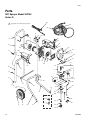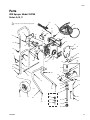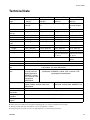
1
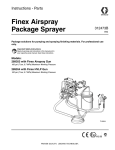
Repair and Parts
Airless Sprayers
US Patent No. 1184US3
309226M
EN
- For portable spray applications of architectural paints and coatings - (Specifications, page 3.)
Important Safety Instructions
Use water-based or mineral spirit-type material only.
Do not use materials having flash points lower than
70°F (21°C). For information about your material
request MSDS from distributor or retailer.
MAGNUM dx
MODEL 232735
Read all warnings and instructions in this manual. Save
these instructions. See page 3 for model and series
information, including dispense rate, recommended hose
length, guns, and maximum working pressure.
MAGNUM XR5
MODEL 232740
ti4309a
ti6877a
MAGNUM XR7
MODEL 232745
ti6878a
Related Manuals - 309225 Operation
MAGNUM XR9
MODEL 232750
ti6879a
Contents
Models . . . . . . . . . . . . . . . . . . . . . . . . . . . . . . . . . . . . . . . . . 3
Specifications . . . . . . . . . . . . . . . . . . . . . . . . . . . . . . . . . . . 3
Warnings . . . . . . . . . . . . . . . . . . . . . . . . . . . . . . . . . . . . . . . 4
Installation . . . . . . . . . . . . . . . . . . . . . . . . . . . . . . . . . . . . . 6
Grounding and Electric Requirements . . . . . . . . . . . . . 6
Thermal Overload . . . . . . . . . . . . . . . . . . . . . . . . . . . . . 6
Component Identification . . . . . . . . . . . . . . . . . . . . . . . . . 8
Operation . . . . . . . . . . . . . . . . . . . . . . . . . . . . . . . . . . . . . 10
Pressure Relief Procedure . . . . . . . . . . . . . . . . . . . . . 10
Trigger Lock . . . . . . . . . . . . . . . . . . . . . . . . . . . . . . . . 10
General Repair Information . . . . . . . . . . . . . . . . . . . . . . . 11
Basic Troubleshooting . . . . . . . . . . . . . . . . . . . . . . . . . . . 12
Advanced Troubleshooting . . . . . . . . . . . . . . . . . . . . . . . 15
General Problem: Motor Does Not Operate . . . . . . . . 15
General Problem: Circuit Breaker is Tripping . . . . . . . 17
General Problem: Erratic Motor Operation . . . . . . . . . 18
General Problem: Low or Fluctuating Output . . . . . . . 19
General Problem: No Output . . . . . . . . . . . . . . . . . . . 21
General Problem: Excessive Pressure Build Up . . . . . 21
2
List of Kits . . . . . . . . . . . . . . . . . . . . . . . . . . . . . . . . . . . . 22
Motor Diagnostics . . . . . . . . . . . . . . . . . . . . . . . . . . . . . . 24
Control Board Diagnostics . . . . . . . . . . . . . . . . . . . . . . . 25
Pump Diagnostics . . . . . . . . . . . . . . . . . . . . . . . . . . . . . . 25
Pump Service . . . . . . . . . . . . . . . . . . . . . . . . . . . . . . . . . . 25
Parts . . . . . . . . . . . . . . . . . . . . . . . . . . . . . . . . . . . . . . . . . 26
dx Sprayer Model 232735 . . . . . . . . . . . . . . . . . . . . . . 26
XR5 Sprayer Model 232740 . . . . . . . . . . . . . . . . . . . . 28
XR7 Sprayer Model 232745 . . . . . . . . . . . . . . . . . . . . 32
XR9 Sprayer Model 232750 . . . . . . . . . . . . . . . . . . . . 36
Technical Data . . . . . . . . . . . . . . . . . . . . . . . . . . . . . . . . . 39
Graco Standard Warranty . . . . . . . . . . . . . . . . . . . . . . . . 40
309226M
Models
Models
Model Name,
Model No.
Series
Dispense Rate
gpm (lpm)
Hose
Length and
Diameter
Maximum Working
Pressure
Gun Model
PSI
MPa
bar
Magnum dx
232735
B
0.24 gpm
(0.91 lpm)
25 ft (7.6 m)
3/16 in.
SG1™- EF
2800
19
193
Magnum XR5
232740
E
0.27 gpm
(1.02 lpm)
25 ft (7.6 m)
1/4 in.
SG1™ - EF
3000
21
207
Magnum XR7
232745
D
0.34 gpm
(2.17 lpm)
50 ft (15.2 m)
1/4 in.
SG2™
3000
21
207
Magnum XR9
232750
D
0.38 gpm
(1.44 lpm)
50 ft (15.2 m)
1/4 in.
SG3™
3000
21
207
Specifications
This equipment is not intended for use with flammable or combustible materials used in places such as cabinet shops
or other “factory”, or fixed locations. If you intend to use this equipment in this type of application, you must comply
with NFPA 33 and OSHA requirements for the use of flammable and combustible materials.
309226M
3
Warnings
Warnings
The following are general warnings related to the setup, use, grounding, maintenance, and repair of this equipment.
Additional, more specific warnings may be found throughout the body of this manual where applicable. Symbols
appearing in the body of the manual refer to these general warnings. When these symbols appear throughout the
manual, refer back to these pages for a description of the specific hazard.
WARNING
FIRE AND EXPLOSION HAZARD
Flammable fumes, such as solvent and paint fumes, in work area can ignite or explode. To help prevent
fire and explosion:
• Use equipment only in well ventilated area.
• Eliminate all ignition sources; such as pilot lights, cigarettes, portable electric lamps, and plastic drop
cloths (potential static arc).
• When flammable liquid is used in or near the sprayer or for flushing or cleaning, keep sprayer at least
20 feet (6 m) away from explosive vapors.
• Do not clean with materials having flash points lower than 70°F (21°C). Use water-based materials
or mineral spirits type material only. For complete information about your material, request the
MSDS from the fluid distributor or retailer.
• Keep work area free of debris, including solvent, rags and gasoline.
• Do not plug or unplug power cords or turn lights on or off when flammable fumes are present.
• Ground all equipment in work area. See Grounding instructions.
• If there is static sparking or you feel a shock, stop operation immediately. Do not use equipment
until you identify and correct the problem.
• Keep a fire extinguisher in the work area.
ELECTRIC SHOCK HAZARD
Improper grounding, setup, or usage of the system can cause electric shock.
• Turn off and disconnect power cord before servicing equipment.
• Use only grounded electrical outlets.
• Use only 3-wire extension cords.
• Ensure ground prongs are intact on sprayer and extension cords.
• Do not expose to rain. Store indoors.
SKIN INJECTION HAZARD
High-pressure fluid from gun, hose leaks, or ruptured components will pierce skin. This may look like just
a cut, but it is a serious injury that can result in amputation. Get immediate surgical treatment.
• Do not point gun at anyone or at any part of the body.
• Do not put your hand over the spray tip.
• Do not stop or deflect leaks with your hand, body, glove, or rag.
• Engage trigger lock when not spraying.
• Follow Pressure Relief Procedure in this manual, when you stop spraying and before cleaning,
checking, or servicing equipment.
SKim
4
309226M
Warnings
WARNING
EQUIPMENT MISUSE HAZARD
Misuse can cause death or serious injury.
• Do not exceed the maximum working pressure or temperature rating of the lowest rated system
component. See Technical Data in all equipment manuals.
• Use fluids and solvents that are compatible with equipment wetted parts. See Technical Data in all
equipment manuals. Read fluid and solvent manufacturer’s warnings. For complete information
about your material, request MSDS from distributor or retailer.
• Check equipment daily. Repair or replace worn or damaged parts immediately with genuine Graco
replacement parts only.
• Do not alter or modify equipment.
• Use equipment only for its intended purpose. Call your Graco distributor for information.
• Route hoses and cables away from traffic areas, sharp edges, moving parts, and hot surfaces.
• Do not kink or over bend hoses or use hoses to pull equipment.
• Keep children and animals away from work area.
• Comply with all applicable safety regulations.
• Do not operate the unit when fatigued or under the influence of drugs or alcohol.
PRESSURIZED ALUMINUM PARTS HAZARD
Do not use 1,1,1-trichloroethane, methylene chloride, other halogenated hydrocarbon solvents or fluids
containing such solvents in pressurized aluminum equipment. Such use can cause serious chemical
reaction and equipment rupture, and result in death, serious injury, and property damage.
TOXIC FLUID OR FUMES HAZARD
Toxic fluids or fumes can cause serious injury or death if splashed in the eyes or on skin, inhaled, or
swallowed.
• Read MSDS’s to know the specific hazards of the fluids you are using.
• Store hazardous fluid in approved containers, and dispose of it according to applicable guidelines.
BURN HAZARD
Equipment surfaces can become very hot during operation. To avoid severe burns, do not touch hot
equipment. Wait until equipment has cooled completely.
PERSONAL PROTECTIVE EQUIPMENT
You must wear appropriate protective equipment when operating, servicing, or when in the operating
area of the equipment to help protect you from serious injury, including eye injury, inhalation of toxic
fumes, burns, and hearing loss. This equipment includes but is not limited to:
• Protective eye wear
• Clothing and respirator as recommended by the fluid and solvent manufacturer
• Gloves
• Hearing protection
309226M
5
Installation
Installation
Grounding and Electric
Requirements
The sprayer must be grounded. Grounding reduces the
risk of static and electric shock by providing an escape
wire for the electrical current due to static build up or in
the event of a short circuit.
The sprayer requires a 120V AC, 60 Hz, 15A circuit
with a grounding receptacle. Never use an outlet that is
not grounded or an adapter.
Smaller gauge or longer extension cords may
reduce sprayer performance.
Spray gun: ground through connection to a properly
grounded fluid hose and pump.
Fluid supply container: follow local code.
Solvent pails used when flushing: follow local code.
Use only conductive metal pails, placed on a grounded
surface such as concrete. Do not place the pail on a
nonconductive surface, such as paper or cardboard,
which interrupts grounding continuity.
Grounding the metal pail: connect a ground wire to the
pail by clamping one end to pail and other end to ground
such as a water pipe.
Maintain grounding continuity when flushing or
relieving pressure: hold metal part of the spray gun
firmly to the side of a grounded metal pail, then trigger
the gun.
Do not use the sprayer if the electrical cord has a damaged ground prong.
Thermal Overload
Motor has a thermal overload switch to shut itself down
if overheated.
Only use an extension cord with an undamaged
3-prong plug. Recommended extension cords for use
with this sprayer:
•
•
•
•
6
25 ft (7.6 m) 18 AWG
50 ft (15.2 m) 16 AWG
100 ft (30.5 m) 14 AWG
150 ft (45.7 m) 12 AWG
To reduce risk of injury from motor starting
unexpectedly when it cools, always turn power
switch OFF if motor shuts down.
309226M
Installation
Notes
309226M
7
Component Identification
Component Identification
A
Electric motor (inside enclosures)
Provides mechanical power to pump.
B
Power switch
Manually turns ON and OFF electric power to motor (I is ON
and 0 is OFF.
C
Pressure control knob
Manually increases (turn clockwise) and decreases (turn
counter-clockwise) fluid pressure in pump, hose, and spray
gun.
D
Pump fluid outlet fitting
Threaded connection for paint hose.
E
InstaClean™ fluid filter (XR models only)
•
•
F
Power-Piston™ pump (behind Easy
Access door)
Pumps and pressurizes fluid and delivers it to paint hose.
Easy Access door permits quick removal of outlet valve.
G
Suction tube
Draws fluid from paint pail into pump.
H
Prime tube (with diffuser)
Drains fluid in system during priming and pressure relief.
J
Spray- Prime/Drain valve control
•
•
•
In SPRAY position (pointing forward) directs pressurized
fluid to paint hose.
In PRIME/DRAIN position (pointing down) directs fluid to
drain tube.
Automatically relieves system pressure in overpressure
situations.
K
Fluid inlet connection and inlet valve
Suction tube connection to pump and inlet valve.
L
Inlet screen
Prevents debris from entering pump.
M
Paint hose
Transports high-pressure fluid from pump to spray gun.
N
Cord wrap bracket
Stows electrical cord (XR5 model only).
P
Airless spray gun
Dispenses pumped fluid.
Q
Tip guard
Reduces risk of fluid injection injury.
R
Reversible spray tip
•
•
8
Filters fluid coming out of pump to reduce tip plugging
and improve finish.
Self cleans only during pressure relief.
Atomizes fluid being sprayed, forms spray pattern and
controls fluid flow according to hole size.
Reverses for unclogging plugged tips without disassembly.
S
Trigger safety lever
Prevents accidental triggering of spray gun.
T
Gun fluid inlet fitting
Threaded connection for paint hose.
U
Smooth Glide™ swivel (SG3 spray gun
only)
Allows spray gun to swivel without twisting paint hose.
V
Gun fluid filter (in handle)
Filters fluid entering spray gun to reduce tip clogs and
improve finish.
W
Hose/cord wrap bracket
Stows paint hose and electrical cord (XR7 and XR9 models
only).
X
Pail hanger
For transporting pail by its handle (XR7 and XR9 models
only).
Y
Power Flush attachment (included)
Connects garden hose to suction tube for power flushing
water-base fluids.
309226M
Component Identification
Sprayers
Magnum XR5
Magnum XR7
!
"
W
*
.
(
X
&
#
$
+
'
K
,
Connect cart handles on XR7 and XR9 as follow:
1. Position handle on frame as shown and align
bolt holes in handle with bolt holes in frame.
-
0
2. Run bolts through holes with heads pointing
toward each other, and hand tighten wingnuts.
%
TIA
NOTE: For space-saving configuration, loosen,
(but do not remove) wingnuts.
Fold handle forward over sprayer shroud.
Magnum dx
Magnum XR9
D
W
B
K
W
X
TIA
K
Spray Guns
S
S
R
R
Q
Q
V
U
V
T
T
9562A
9561A
309226M
9
Operation
Operation
Pressure Relief Procedure
4. Engage trigger lock. See Trigger Lock, page 10 or
your gun operation manual.
Follow Pressure Relief Procedure when you stop spraying and before cleaning, checking, servicing, or transporting equipment. Read warnings, page 4.
Leave Spray - Prime/Drain valve in the
PRIME/DRAIN position until you are ready to spray
again.
1. Turn power switch (B) OFF and unplug power cord.
If you suspect the spray tip or hose is clogged or that
pressure has not been fully relieved after following the
steps above, VERY SLOWLY loosen tip guard retaining
nut or hose end coupling to relieve pressure gradually,
then loosen completely. Clear hose or tip obstruction.
Trigger Lock
Always engage the trigger lock when you stop spraying
to prevent the gun from being triggered accidentally by
hand or if dropped or bumped.
2. Turn Spray- Prime/Drain valve (J) to PRIME/DRAIN
to relieve pressure.
Trigger Locked Position
(SG1-EF)
(SG2 and SG3)
PRIME
3. Hold a metal part of the gun firmly to a grounded
metal pail. Trigger the gun to relieve pressure.
10
309226M
General Repair Information
General Repair Information
To reduce risk of serious injury, including electric shock:
Flammable materials spilled on hot, bare, motor could
cause fire or explosion. To reduce risk of burns, fire
or explosion, do not operate sprayer with cover
removed.
•
Keep all screws, nuts, washers, gaskets, and electrical fittings removed during repair procedures. These
parts usually are not provided with replacement kits.
•
Test repairs after problems are corrected.
•
If sprayer does not operate properly, review repair
procedure to verify you did it correctly. See Basic
Troubleshooting, page 12 and Advanced Troubleshooting, page 15.
•
Overspray may build up in the air passages.
Remove any overspray and residue from air passages and openings in the enclosures whenever
you service sprayer.
•
Do not operate the sprayer without the cover in
place. Replace if damaged. Covers direct cooling air
around motor to prevent overheating.
309226M
•
Do not touch moving or electric pars with fingers or
tools while testing repair.
•
Unplug sprayer when power is not required for testing.
•
Install all covers, gaskets, screws and washers
before you operate sprayer.
•
CAUTION
Do not run sprayer dry for more than 30 seconds.
Doing so could damage pump packings.
•
Protect the internal drive parts of this sprayer from
water. Openings in the cover allow for air cooling of
the mechanical parts and electronics inside. If
water gets in these openings, the sprayer could
malfunction or be permanently damaged.
•
Prevent pump corrosion and damage from freezing.
Never leave water or water-base paint in sprayer
when its not in use in cold weather. Freezing fluids
can seriously damage sprayer. Store sprayer with
Pump Armor to protect sprayer during storage.
11
Basic Troubleshooting
Basic Troubleshooting
The following troubleshooting guidelines from the Operating Instructions are included here as a preemptive measure
against Advanced Troubleshooting, page 15. Refer to Component Identification, page 8 for reference letters
used in table.
Problem
Power switch is on and sprayer is
plugged in, but motor does not run,
and pump does not cycle.
Cause
Solution
Pressure is set at zero pressure.
Turn Pressure Control Knob (C)
clockwise to increase pressure setting.
Motor or control is damaged.
See Motor Does Not Operate, page
15.
Electric outlet is not providing power. •
•
Pump does not prime.
Spray gun stopped spraying.
12
Try a different outlet or plug in
something that you know is working to test outlet.
Reset building circuit breaker or
replace fuse.
Extension cord is damaged.
Replace extension cord. See
Grounding and Electric Requirements, page 6.
Sprayer electric cord is damaged.
Check for broken insulation or wires.
Replace electric cord if damaged.
Paint is frozen or hardened in pump.
See Motor Does Not Operate, page
15.
Spray-Prime/Drain Valve (J) is in
SPRAY position.
Turn Spray-Prime/Drain Valve to
PRIME/DRAIN position (pointing
down).
Inlet screen (L) is clogged or suction
tube (G) is not immersed.
Clean debris off inlet screen and
make sure suction tube is at bottom
of paint pail.
Balls in check valve are stuck or
check valves are damaged.
Clean or replace check valves. See
Pump Service, page 25. Do not
store check valves in water.
Suction tube is leaking.
Tighten suction tube connection (K).
Inspect for cracks or vacuum leaks.
Spray tip is clogged.
Unclog spray tip. See Operation Manual, 309225.
309226M
Basic Troubleshooting
Problem
Pump cycles but does not build up
pressure.
Cause
Solution
Pump is not primed.
Prime pump.
Inlet screen (L) is clogged or suction
tube (G) is not immersed.
Clean debris off inlet screen and
make sure suction tube is at bottom
of paint pail.
Paint pail is empty.
Refill paint pail. Reprime sprayer.
Suction tube is leaking.
Tighten suction tube connection (K).
Inspect for cracks or vacuum leaks.
Pump check valves are dirty or dam- Clean or replace check valves. See
aged. (Usually only one valve).
Pump Service on page 25.
Pump cycles, but paint only dribbles
or spurts when spray gun is triggered.
Spray pattern is inconsistent or is
leaving stripes.
Spray-Prime/Drain Valve (J) is worn
or obstructed with debris.
Check Spray-Prime/Drain valve for
debris trapped on seat or worn parts.
Torque to 185 in-lbs (21 N•m).
Replace if parts are worn.
Pressure is set too low.
Slowly turn Pressure Control Knob
(C) clockwise to increase pressure
setting and verify if sprayer pressure
increases.
Spray tip is clogged.
Unclog spray tip. See Operation Manual 309225.
InstaClean fluid filter is clogged (XR
models only).
Clean or replace InstaClean fluid filter (E).
Spray gun fluid filter is clogged or
installed backward.
Clean or replace gun fluid filter (V).
Pressure is set too low.
Turn Pressure Control Knob (C)
clockwise, to increase pressure.
Spray tip is worn beyond capability of Replace spray tip.
sprayer.
Pressure is set at maximum but
Spray tip is too large for sprayer.
Select smaller spray tip.
cannot achieve a good spray pattern. Spray tip is worn beyond capability of Replace spray tip.
sprayer.
309226M
Extension cord is too long or not
heavy enough gauge.
Replace extension cord. Grounding
and Electrical Requirements, page
6.
Spray gun fluid filter is clogged.
Clean or replace spray gun fluid filter.
InstaClean fluid filter is clogged (XR
models only).
Clean or replace InstaClean fluid
filter.
Inlet screen is clogged.
Clean debris off inlet screen.
Pump valves are worn.
See Low or Fluctuating Output,
page 19.
13
Basic Troubleshooting
Problem
Motor is hot and runs intermittently.
This is NOT a thermal overload condition. Motor automatically shuts off
due to excessive heat. Damage can
occur if cause is not corrected.
Startup Hazard After Thermal
Overload, page 6.
Cause
Solution
Vent holes in enclosure are plugged
or sprayer is covered.
Keep vent holes clear of obstructions
and overspray and keep sprayer
open to air.
Extension cord is too long or not a
heavy enough gauge.
Replace extension cord. See
Grounding and Electrical
Requirements, page 6.
Unregulated electrical generator
being used has excessive voltage.
Use electrical generator with a proper
voltage regulator. Sprayer requires
120VAC, 60 Hz, 1500-Watt
generator.
Sprayer was operated at high
pressure with very small tip which
causes frequent motor starts and
excessive heat build up.
Decrease pressure setting or
increase tip size.
Building circuit breaker opens after
Too many appliances are plugged in
sprayer operates for 5 to 10 minutes. on same circuit.
Sprayer electrical cord is damaged.
Free up circuit (unplug things), or use
a less busy circuit.
Check broken insulation or wires.
Replace electrical cord if damaged.
Fan pattern varies dramatically while Pressure control switch is worn and Replace pressure control knob using
causing excessive pressure variation. Pressure Control Switch Kit, page
spraying.
22.
OR
Sprayer does not turn on promptly
when resuming spraying.
Cannot trigger spray gun.
Spray gun trigger safety is unlocked.
Rotate trigger safety lever to lock
SAFETY, page 10.
Spray comes out of spray gun in two
thick streams.
Reversible spray tip is in UNCLOG
position.
Rotate arrow-shaped handle on
spray tip so it points forward in
SPRAY position.
Paint is coming out of pressure
control switch.
Pressure control switch is worn.
Replace pressure control using
Pressure Control Switch Kit, page
22.
Spray-Prime/Drain valve actuates
automatically relieving pressure
through drain tube.
System is over pressurizing.
See Excessive Pressure Build Up,
page 21.
Paint leaks down outside of pump.
Pump packings are worn.
Replace pump packings. See Pump
Service, page 25.
14
309226M
Advanced Troubleshooting
Advanced Troubleshooting
See Basic Troubleshooting first, page 12 for problems that are more easily remedied.
General Problem: Motor Does Not Operate
Specific Problem
Cause
Solution
Power switch is on and sprayer See Basic Troubleshooting,
is plugged in; pump does not
page 12.
cycle.
Basic mechanical problems.
Paint is frozen or hardened in
pump.
Unplug sprayer from electrical outlet.
If paint is frozen in sprayer:
•
Do NOT try to start sprayer until completely
thawed or you may damage the motor, control
board, and/or drivetrain.
1. Turn OFF power switch.
2. Place sprayer in warm area for several
hours.
3. Plug in and turn on sprayer.
4. Slowly increase pressure until motor starts.
If paint hardened in sprayer:
1. Replace pump packings.
2. Remove all residue from valves.
Pump Service, page 25.
309226M
Motor is damaged.
Remove gear and try to rotate motor shaft by
hand. See Motor Diagnostics, page 24. If shaft
will not turn, replace motor using Motor Kit, page
22.
Yoke is broken because pump
is locked up due to dried paint
or worn packings (XR models
only).
Repair or replace using Gear/Yoke Kit, page 22.
Repair pump. See Pump Service, page 25.
15
Advanced Troubleshooting
Specific Problem
Basic electrical problems.
Sprayer Wiring Problems
NOTE: Remove enclosure
mounting screws and pull
enclosure away from drive
housing. Take care not to pull
on leads from electrical cord
and power switch.
16
Cause
Solution
Motor overheated.
Allow motor to cool for 30 minutes. Retry.
Electrical outlet is damaged.
Reset building circuit breaker or replace fuse. Try
another outlet.
Check electric supply with volt meter. Meter must
read 85 to 130V AC. If voltage is too high, do not
plug sprayer in until outlet is corrected.
Control board leads are
improperly fastened or
improperly mated.
Replace any loose terminals. Make sure all leads
and harnesses are firmly connected.
Check pressure control harness connection on
front side of drive housing.
Clean control board terminals. Securely reconnect
leads.
Motor brushes are worn.
Check length of BOTH brushes (brushes do not
wear evenly on both sides of the motor). Brush
length must be 0.25 in. (6.4mm). If brushes are
worn replace motor using Motor Kit, page 22.
Motor armature commutator
damaged.
Check for burn spots, gouges and extreme
roughness. Have motor shop resurface
commutator if possible, or replace motor using
Motor Kit, page 22.
Fuse is blown.
Replace fuse using Fuse Kit, page 22.
Motor armature shorting.
Check for shorts using armature tester (growler)
or perform spin test, Motor Diagnostic, page 24.
If shorts are evident, replace motor using Motor
Kit, page 22.
Control board damaged.
CAUTION: Do not perform
control board diagnostics until
you have determined the
armature is good. A bad
armature can burn out a good
control board.
See Control Board Diagnostics, page 25.
Replace control board if damaged using Control
Board Kit, page 22.
Sprayer electrical cord
damaged.
1. Unplug sprayer electrical cord.
2. Disconnect black electrical cord wire at
power switch.
3. Unplug in-line connection white cord wire.
4. Plug in electrical cord.
5. Test voltage between black and white
wires. Meter must read 85 to 130V AC.
6. Replace electrical cord if no voltage.
Sprayer power switch
damaged.
1. Unplug sprayer electrical cord.
2. Disconnect black control board wire at
power switch.
3. Unplug in-line connection white cord wire.
4. Plug in electrical cord.
5. Turn power switch ON.
6. Test voltage between open terminal of
power switch and white electrical cord wire.
Meter must read 85 to 130V AC.
7. Replace power switch if no voltage.
309226M
Advanced Troubleshooting
Specific Problem
Cause
Sprayer Wiring Problems
(cont.)
Motor thermal overload cutoff
switch damaged.
Startup Hazard After Thermal
Overload, page 6.
Terminals are damaged or
loose.
Solution
1. Unplug sprayer electrical cord.
2. Remove motor harness from control card.
3. Check for continuity between yellow leads
or motor harness.
4. If thermal relief switch is open (no continuity) allow motor to cool.
5. If switch remains open after motor cools,
replace motor using Motor Kit, page 22.
6. If thermal relief switch closes after motor
cools, find correct cause of overheating.
Replace any damaged terminals. Make sure all
terminal connections are tight.
General Problem: Circuit Breaker is Tripping
Specific Problem
Building circuit breaker opens
as soon as sprayer is turned
on.
Cause
Sprayer electrical wiring is
pinched or insulation is
damaged.
Solution
Repair or replace any damaged wiring or
terminals. Securely reconnect wires.
Wires between pressure
control switch and control
board are pinched.
Motor armature is shorting.
Check for shorts using armature tester (growler)
or perform spin test, Motor Diagnostics, page
24. If shorts are evident, replace motor using
Motor Kit, page 22.
See Control Board Diagnostics, page 25.
Control board is damaged.
Replace control board if damaged using Control
CAUTION: Do not perform
control board diagnostics until Board Kit, page 22.
you have determined the
armature is good. A bad motor
armature can burn out a good
motor control board.
309226M
17
Advanced Troubleshooting
Specific Problem
Cause
Building circuit breaker opens
as soon as sprayer is plugged
into outlet and sprayer is NOT
turned on.
NOTE: Remove enclosure
mounting screws and pull
enclosure away from drive
housing. Take care not to pull
on leads from electrical cord
and power switch.
Solution
Sprayer electrical cord is
damaged.
1. Unplug sprayer electrical cord.
2. Disconnect black electrical cord wire at
power switch.
3. Unplug in-line connection white cord wire.
4. Plug in electrical cord.
5. Test voltage between black and white
wires. Meter must read 85 to 130V AC.
6. Replace electrical cord if no voltage.
Sprayer power switch
damaged.
1. Unplug sprayer electrical cord.
2. Disconnect black control board wire at
power switch.
3. Check resistance of switch with ohmmeter.
4. Reading must be infinity with power switch
OFF.
5. Reading must be zero with power switch
ON.
6. Replace power switch if damaged.
Also see Basic Electrical Problems and Sprayer Wiring Problems, page 16.
General Problem: Erratic Motor Operation
Specific Problem
Sprayer quits after running for
5 to 10 minutes
Cause
Solution
Electrical outlet is damaged
Reset building circuit breaker or replace building
fuse.
Electrical outlet supplying
wrong voltage
Try another outlet. Check electric supply with volt
meter. Meter must read 85 to 130V AC. If voltage
is too high, do not use outlet until corrected.
Also see Basic Electrical Problems and Sprayer Wiring Problems, page 16.
Motor is overheating
Motor is hot and runs
intermittently.
18
See Motor is Hot, page 14.
See Basic Troubleshooting, page 12.
309226M
Advanced Troubleshooting
General Problem: Low or Fluctuating Output
Specific Problem
Pump cycles, but output is low
or surging.
Cause
Solution
See Basic Troubleshooting,
page 12.
Worn or obstructed pump
valves.
Check for worn pump valves as follows:
Spray-Prime/Drain valve is
leaking.
Check Spray-Prime/Drain valve for debris trapped
on seat and for worn parts. Torque to 185 in-lb (21
N•m). Replace if parts are worn using
Prime/Spray Drain Valve Kit, page 22.
1. Prime sprayer with paint.
2. Trigger spray gun momentarily.
3. When spray gun trigger is released pump
should cycle momentarily and stop.
4. If pump continues to cycle, pump valves
may be worn or obstructed.
5. Pump Service, page 25.
Voltage from electrical outlet is Check voltage of outlet. Meter must read 85 to
too low. Low voltages reduce
130V AC.
Reset building circuit breaker or replace building
sprayer performance.
fuse.
Repair electrical outlet or try another outlet.
Extension cord is too long or
not heavy enough gauge.
Replace extension cord.
Grounding and Electrical Requirements, page
6.
Leads from motor or pressure
switch to control board are
damaged, loose, pinched, or
overheated.
Be sure terminals are centered and firmly
connected. Inspect for pinched wiring and wiring
insulation and terminals for signs of overheating.
Replace any loose terminals or damaged wiring.
Securely reconnect terminals.
Motor brushes are worn.
Check length of BOTH brushes (brushes to not
wear evenly on both sides of the motor). Brush
length must be 0.25 in. (6.4mm). If brushes are
worn replace motor using Motor Kit, page 22.
Motor brush springs are
broken.
If springs are broken replace motor using Motor
Kit, page 22.
Motor brushes are binding in
brush holders.
Clean brush holders. Remove carbon dust with
small cleaning brush.
Motor stops before sprayer
Replace pressure control using Pressure Control
reaches correct pressure (stall Switch Kit, page 22.
pressure is too low).
Motor armature shorted.
309226M
Check for shorts using armature tester (growler)
or perform spin test, Motor Diagnostics, page
24. If shorts are evident, replace motor using
Motor Kit, page 22.
19
Advanced Troubleshooting
Specific Problem
Cause
Solution
See Control Board Diagnostics, page 25. If
Control board is damaged.
damaged replace control board using Control
CAUTION: Do not perform
control board diagnostics until Board Kit, page 22.
you have determined the
armature is good. A bad motor
can burn out a good control
board.
Motor runs and pump cycles,
Intake valve ball or outlet valve Remove and clean valves and check balls and
but pressure does not build up. ball is not seating properly.
seats for nicks; replace if necessary. Strain paint
before spraying to remove particles that could clog
pump. Pump Service, page 25.
Pump packings are worn or
damaged.
Check for leaking around throat packing nut.
Replace pump packings if there are leaks. Pump
Service, page 25.
Prime/Spray Valve leaking.
Check Prime/Spray Valve for debris trapped on
seat and for worn parts. Torque to 185 in-lb (21
N•m). If parts are worn, replace valve using
Prime/Spray Drain Valve Kit, page 22.
Leads from motor or pressure
Spray pattern has variations,
switch to control board are
pressure fluctuates
excessively, or motor runs very damaged, loose or overheated
slowly.
20
Be sure terminals are centered and firmly
connected. Inspect wiring insulation and terminals
for signs of overheating. Replace any loose
terminals or damaged wiring. Securely reconnect
terminals.
Pressure control switch leads
are pinched between pump
and drive housing or between
front cover and drive housing
(XR models only)
Make sure pressure control harness is routed
behind pump, through retention clip and
connected to control board connector on control
board (connect with tab to right).
Control board is damaged.
CAUTION: Do not perform
control board diagnostics until
you have determined the
armature is good. A bad
armature can burn out a good
control board.
See Control Board Diagnostics, page 25. If
damaged, replace control board using Control
Board Kit, page 22.
Pressure control switch is
damaged or worn out.
Replace pressure control switch using Pressure
Control Switch Kit, page 22.
309226M
Advanced Troubleshooting
General Problem: No Output
Specific Problem
Cause
Solution
Power switch is on and sprayer See Basic Troubleshooting,
is plugged in but pump does
page 12.
not cycle
Motor runs but pump does not
cycle.
Gear and/or yoke are damaged Replace gear and yoke using Gear/Yoke Repair
(XR models only).
Kit, page 22.
Motor does not run.
Water or paint entered
pressure control switch or
shorted control board.
Clean out and/or dry out and retry. Replace if
necessary using Pressure Control Switch Kit,
page 22.
General Problem: Excessive Pressure Build Up
Specific Problem
Prime/Spray Valve actuates
automatically, relieving
pressure through drain tube.
309226M
Cause
Solution
Pressure control switch is
worn.
Replace pressure control switch using Pressure
Control Switch Kit, page 22.
Water or paint entered
pressure control switch or
shorted control board.
Clean out and/or dry out and retry. Replace if
necessary using Pressure Control Switch Kit,
page 22.
Control board failed.
See Control Board Diagnostics, page 24.
Replace damaged control board using Control
Board Kit, page 22.
21
List of Kits
List of Kits
Kit Number
Models/Series
243230
235014
245077
245070
243093
XR5, Series A and B
XR7 and XR9, Series A
XR5, Series C, D, E
XR7 and XR9, Series B
and C, D
dx
XR5 and XR7
XR9
All models
XR5, Series A, B, C, D
XR5, Series E
XR7 and XR9, Series A,
B, C
XR7 and XR9, Series D
XR5, Series A, B, C, D
XR7 and XR9, Series A,
B, C
XR5, Series E
XR7 and XR9, Series D
XR5, Series A and B
XR7 and XR9, Series A
XR5, Series C, D, E
XR7 and XR9, Series B,
C, D
XR5 and XR7
XR9
All models
dx
XR5, Series A and B
XR7 and XR9, Series A
XR5, Series C
All XR7 and XR9, Series
B and C
XR5, Series E
XR7 and XR9, Series D
dx and XR5, Series A
XR 5, Series B, C, D, E
XR7 and XR9
All models
dx
All XR models
All XR models
245076
243094
dx
All XR models
245062
245079
243228
243229
244035
243232
287771
243234
287772
243231
287770
243237
245064
119276
119277
243082
245080
243236
245063
287773
244266
244267
22
Kit Description
10 mm Shaft, gear, yoke, guides (ball bearing equipped cover and motor castings)
3/8 in. Shaft gear, yoke, guides (bronze bearing equipped cover and motor castings)
Control Board
Control Board
Control Board
Drain Tube Diffuser
Enclosure (includes both sides, labels and screws)
Enclosure (includes both sides, labels and screws)
Enclosure (includes both sides, labels and screws)
Enclosure (includes both sides, labels and screws)
Fan, shroud, brace
Fan replacement
Front cover (10 mm ball bearing)
Front cover (3/8 in. bronze bearing)
Fuse, 12.5 Amp
Fuse, 16 Amp
Inlet Strainer (or inlet of suction tube)
Motor repair
Motor, drive housing (10 mm ball bearing motor casting - includes fan, shroud and
brace)
Motor, drive housing (3/8 in. bronze bearing motor casting - includes fan, shroud and
brace)
Motor, drive housing (3/8 in. bronze bearing motor casting - includes fan, shroud and
brace)
Pressure Control Switch
Pressure Control Switch
Prime/Spray Drain Valve
Pump Inlet Valve Module (use with Suction Tube 196582 or 197608 only)
Pump Inlet Valve Module (use with Suction Tube 197607, 197608, or 15D671 only)
Pump Inlet Valve Module (1/2 in. NPT bottom port) (Alternate Style, page 28 - 37 use with Suction Tube 195750 or 195883 only)
Pump Outlet Valve Module
Pump Outlet Valve Module
309226M
List of Kits
Kit Number
245078
243090
243533
Models/Series
dx
All XR models
All XR models
196582
197608
195750
dx, Series A
dx, Series B
XR5
197607
XR5
195883
XR7 and XR9, Series A
197608
XR7 and XR9, Series B
15D671
XR7 and XR9,
Series C, D
XR7 and XR9,
Series C, D
248202
309226M
Kit Description
Pump repair
Pump Repair (pump packing module)
Pump replacement (compete pump*)
* Does not include Pressure Control Switch 244267. Reuse Pressure Control Switch
from pump being replaced, or order separately.
Suction Tube (Use with Pump Inlet Valve Module 245077 only)
Suction Tube (Use with Pump Inlet Valve Module 245077 only)
Suction Tube (inlet valve with 1/2 in. NPT bottom port; 115628 plastic elbow) (Alternate Style, page 28 - 37 - Use with Pump Inlet Valve Module 243093 only)
Suction Tube (Inlet valve with integral hose barb; no elbow) (Use with Pump Inlet
Valve Module 245070 only)
Suction Tube (inlet valve with 1/2 in. NPT bottom port) (Alternate Style, page 28 - 37 Use with Pump Inlet Valve Module 243093 only)
Suction Tube (inlet valve with integral hose barb) (Use with Pump Inlet Valve Module
245070 only)
Suction Tube (inlet valve with integral hose barb) (Use with Pump Inlet Valve Module
245070 only)
Lacquer Conversion (lacquer compatible suction tube and seals)
23
Motor Diagnostics
Motor Diagnostics
Check for electrical continuity in motor armature, windings and brush as follows:
If Motor Diagnostics reveal a damaged motor or if motor brushes are shorter than 1/4 in. (6.4 mm) or if the motor
shaft cannot turn, replace the motor using Motor Kit, page 22.
Armature Short Circuit Spin Test (XR models only)
Setup
1. Relieve pressure, page 10.
2. Unplug electric cord.
3. Remove enclosure and disconnect motor leads from
control card.
4. Remove fan brace.
5. Remove four screws and front cover.
6. Remove yoke and guide rods.
7. Remove gear.
Quickly turn motor fan by hand. There should not be
electrical shorts and fan should coast two or three
revolutions before stopping. If fan does not spin freely,
armature is shorted. Replace motor using Motor Kit,
page 22.
Armature, Brushes and Motor Wiring Open Circuit
Test (Continuity) (XR models only)
1. Connect red and black motor leads together with
test lead.
2. Turn motor fan by hand, about two revolutions per
second.
3. If there is an uneven resistance or no resistance,
replace motor using Motor Kit, page 22.
24
309226M
Control Board Diagnostics
Control Board Diagnostics
Check for motor problems before replacing control board. A damaged motor may burn out a good
control card
Check for a damaged control board or pressure control switch as follows:
1. Relieve pressure, page 10.
Pressure control switch does not have to be
installed in pump.
2. Unplug electrical cord.
3. Remove four cover screws and front cover (XR9).
Remove motor enclosure (dx).
8. Turn pressure control adjustment knob (C) +to maximum pressure setting.
4. Remove yoke and guide rods (XR models only).
9. Plug electrical cord into 120VAC receptacle.
5. Remove gear (XR models only).
10. Turn power switch (B) ON.
6. Remove pressure control harness from control
board. Using tip of small, flat blade screwdriver,
press tab on right side connector to release.
7. Attach harness from a pressure control switch you
know is functioning correctly to control board.
•
•
If motor runs, replace pressure switch.
Pressure Control Switch Kit, page 22.
If motor does not run, replace control board
repeat test. Control Board Kit, page 22.
Pump Diagnostics
CAUTION
When repairing or cleaning the pump, never
submerge pump in water or allow fluid to enter
pressure control.
When pump packings wear, paint begins to leak down
outside of pump. Replace pump packings at the first
sign of leaking or additional damage to drive train could
occur. Use Pump Repair Kit, page 22.
Pump Service
CAUTION
When repairing or cleaning pump, never
submerge pump in water or allow fluid to enter
pressure control.
309226M
If sprayer continues to cycle (motor and pump run) when
the spray gun trigger is released, or if performance is
poor even with new spray tips and clean filters, the
pump inlet or outlet valve may be obstructed or worn. If
a pump is worn, replace it. List of Kits, page 22.
25
Parts
Parts
dx Sprayer Model 232735
Ref
No.
1
13
23
30
31
32
38
41
Part No.
196569
15A680
243082
244035
195400
196582
197608
196586
195084
195108
115489
244266
224807
235014
111600
187625
245148
42
245147
44
245149
50
51
52
245078
245079
245080
2
3
4
5
7
12
26
Description
Qty
FRAME, Series A, includes two #60
1
FRAME. Series B, includes two #60
1
STRAINER
1
DEFLECTOR, barbed
1
CLIP, spring
1
TUBE, suction, Series A
1
TUBE, suction, Series B
1
COVER, switch
1
TUBE, spray, Series A
1
TUBE, spray, Series B
1
CLAMP, drain tube
2
KIT, pressure switch repair
1
CAM, drain valve
1
KIT, valve repair
1
DRIVE PIN, drain valve
1
HANDLE, drain valve
1
KIT, motor enclosure (includes enclosure
1
and 2 warning labels)
KIT, cover, housing (includes 3 labels, 2
1
dowel pins and 2 bushings)
KIT, gear (includes 2 gears and connecting
1
rod)
KIT, pump repair
1
KIT, control board
1
KIT, motor repair
1
Ref
No.
53
54
54a
55
56
57
58
Part No.
245076
245077
C38312
116295
115478
196594
243954
59
243926
60
61▲
62▲
63
64
69
70
71
72
73
105521
15G179
15G180
115477
196574
115648
15H772
112759
116630
102040
Description
KIT, outlet valve
KIT, inlet valve (includes 54a)
O-RING
CLAMP, spring, 0.88 in. diameter.
SCREW, machine, pan head
CORD, power
HOSE, paint, DuraFlex 3/16 in. x 25 ft
(available from service center only)
GUN, spray, SG1-EF (includes manual
309320)
PLUG, tubing
LABEL, warning
LABEL, warning
SCREW, machine, pan head
FITTING, drain
VALVE, shutoff, power flush
FRAME, support
CAP, tubing
SCREW, carriage
NUT, lock, hex
Qty
1
1
1
2
1
1
1
2
1
1
9
1
1
2
4
4
4
▲ Replacement Danger and Warning labels, tags, and
cards are available at no cost.
309226M
Parts
Parts
dx Sprayer Model 232735
42
44
53
30,32,38
31
64
63
13
54a
54
23
4
55
50
52
57
51
12
59
63
7
62
13
5
3
4
58
2
61
1
60
60
56
73
56
5
72
12
70
ti5469b
71
1
309226M
27
Parts
Parts
XR5 Sprayer Model 232740
Ref.
No.
1
2
13
17
18
19
20
Part No.
195126
243090
243094
103338
195947
243070
243093
245070
25
36
103413
244266
244267
40
43
44
45
46
47
235014
224807
187625
111600
119275
243236
245063
48
287773
243231
51
52
54
287770
243228
115477
245109
245062
54a
58
59
61
C38312
194507
116295
115642
62
243237
245064
195110
118900
63
28
Description
Qty.
PUMP, housing
1
KIT, pump repair
1
KIT, outlet valve (includes #17)
1
PACKING, o-ring
1
FILTER, adapter
1
FILTER, InstaClean
1
KIT, inlet valve, 1/2 in. NPT
1
(includes #25) (Alternate Configuration, page 29)
KIT, inlet valve, integral hose barb
1
(includes #25)
PACKING, o-ring, inlet valve
1
KIT, pressure switch, repair,
1
Series A
KIT, pressure switch, repair,
1
Series B, C, D, E
KIT, valve, drain/prime, repair
1
CAM, drive valve
1
HANDLE, drain valve
1
DRIVE PIN, drain valve
1
CLIP, retainer
2
KIT, motor repair, Series A and B
1
(includes fan kit #48)
KIT, motor repair, Series C and D
1
(includes fan kit #48)
KIT, motor repair, Series E
1
KIT, fan repair,
1
Series A, B, C, D
KIT, fan repair, Series E
1
CONTROL BOARD, XR5
1
SCREW, machine
11
KIT, repair, combo; includes Kits
1
245062, 245063, 245064
KIT, gear, yoke, guide, repair,
1
Series C, D, E
O-RING
1
DOWEL, pin, 5/16 in.
2
CLAMP, spring, 0.88 in diameter
1
BUSHING, strain relief,
1
Series A, B, C, D
COVER, with label, Series A and B
1
COVER, with label, Series C, D, E
1
CORD, power, Series A, B, C, D
1
CORD, power, Series E
1
Ref.
No.
65
66
69
70
71
72
73
74
75
76
81
88
90
93
94
95
Part No.
115478
115499
118899
195431
15D922
195430
15D921
105521
15D642
115628
197607
243082
195084
115489
195400
244035
115719
115099
102473
243022
243926
112
114
196001
243232
67
68
287771
127
245053
137
197211
138 119276
140▲ 195812
15G187
141▲ 195121
15G188
142▲ 15E072
143▲ 195122
Description
Qty.
SCREW, torx/slt pan hd, 1/4 in.
8
SWITCH, rocker, Series A, B, C, D
1
SWITCH, rocker, Series E
1
LEG, left, Series A, B and C
1
LEG, left, Series D, E
1
LEG, right, Series A, B, and C
1
LEG, right, Series D, E
1
PLUG
2
HANGER, cord
1
ELBOW, inlet
1
TUBE, suction barb (includes #90)
1
STRAINER
1
TUBE, drain
1
CLAMP, drain tube
2
CLIP, spring
2
DEFLECTOR, barbed
1
O-RING, filter adapter
1
WASHER, inlet strainer
1
CLAMP, hose
1
HOSE, 1/4 in. x 25 ft.
1
GUN, SG1-EF
1
(includes manual 309320)
SPACER, pump
2
ENCLOSURE (includes label 140,
1
141, 142 and screws),
Series A, B, C, D
ENCLOSURE (includes label 140,
1
141, 142 and screws), Series E
1
KIT, pump replacement (includes
#1, 2, 13, 17, 18, 19, 20, 25, 40, 43,
44, 45, 88. Item #36 must be purchased separately)
CAP, pump outlet, Series C, D, E
1
only (includes #62 - 245064)
FUSE
1
LABEL, danger, Series A, B, C, D
1
LABEL, warning, Series E
1
LABEL, warning, Series A, B, C, D
1
LABEL, warning, Series E
1
LABEL, warning
1
LABEL, identification, XR5
1
▲ Replacement Danger and Warning labels, tags, and
cards are available at no cost.
309226M
Parts
Parts
XR5 Sprayer Model 232740
Series A, B, C, D
66
63
Apply light coat of lithium-based grease.
1
61
114
52
48
51
138
62
47
65
137
114
46
54
58
127
112
52
2
1
13
1
17
ti5468b
70
36
40
19
65
43, 44, 45
88 18
75
68
67
25
94
69
95
20
59
75
25
20
72
72
Alternate Config.
93
309226M
74 81
90
71
73
76
29
Parts
Parts
XR5 Sprayer Model 232740
Series E
51
Apply light coat of lithium-based grease.
52
148
47
66
114
52
48
141
62
114
143
65
142
137
46
58
140
54
112
63
127
52
2
1
70
13
1
17
36
40
19
65
ti6881b
43, 44, 45
88 18
75
68
67
25
94
69
95
20
59
75
25
20
72
72
Alternate Config.
93
30
74 81
90
71
73
76
309226M
Parts
Notes
309226M
31
Parts
Parts
XR7 Sprayer Model 232745
Ref.
No.
1
2
13
17
18
19
20
Part No.
195126
243090
243094
103338
195947
243070
243093
245070
25
26
36
40
43
44
45
46
47
103413
116295
244267
235014
224807
187625
111600
119275
243236
245063
48
51
52
54
287773
243231
287770
243228
115477
243230
245062
58
61
194507
111348
62
243237
245064
115603
118901
115478
115499
118899
195433
15D923
195434
15D924
195436
195435
15D650
63
65
66
67
68
69
70
71
32
Description
Qty.
PUMP, housing
1
KIT, pump repair
1
KIT, outlet valve (includes #17)
1
PACKING, o-ring
1
FILTER, adapter
1
FILTER, InstaClean
1
KIT, inlet valve, 1/2 in. NPT
1
(includes #25) (Alternate Configuration, page 33)
KIT, inlet valve, integral hose barb
1
(includes #25)
PACKING, o-ring, inlet valve
1
CLAMP, spring, 0.88 in. diameter
1
KIT, pressure switch, repair,
1
KIT, valve, drain/prime, repair
1
CAM, drive valve
1
HANDLE, drain valve
1
DRIVE PIN, drain valve
1
CLIP, retainer
2
KIT, motor repair, Series A
1
(includes fan kit #48)
KIT, motor repair, Series B and C
1
(includes fan kit #48)
KIT, motor repair, Series D
1
KIT, fan repair, Series A, B, C
1
KIT, fan repair, Series D
1
CONTROL BOARD, XR7
1
SCREW, machine
10
KIT, gear, yoke, guide, repair,
1
Series A
KIT, gear, yoke, guide, repair,
1
Series B, C, D
DOWEL, pin, 5/16 in.
2
BUSHING, strain relief,
1
Series A, B, C
COVER, with label, Series A
1
COVER, with label, Series B, C, D
1
CORD, power, Series A, B, C
1
CORD, power, Series D
1
SCREW, torx/slt pan hd, 1/4 in.
8
SWITCH, rocker, Series A, B, C
1
SWITCH, rocker, Series D
1
LEG, right, Series A, B
1
LEG, right, Series C, D
1
LEG, left, Series A, B
1
LEG, left, Series C, D
1
FRAME, cart
1
HANDLE, cart
1
RACK, hose
1
Ref.
No.
72
73
74
75
76
77
79
80
81
84
85
Part No.
115097
115480
197285
195367
115095
112612
105521
102040
15D658
115099
195883
197608
15D671
86
87
88
89
94
95
96
243082
195108
115489
195400
244035
243024
243011
102
113
125
115719
115651
243234
287772
126
127
196001
245053
149
197211
150 119276
151▲ 195835
15G187
152▲ 195834
15G188
153▲ 15E072
154▲ 195123
Description
Qty.
SCREW, curved head
2
KNOB, t-handle
1
AXLE
1
SPACER
2
WHEEL, 9 in.
2
CAP
2
PLUG
2
NUT, lock
4
HOOK, pail
1
WASHER, inlet strainer
1
TUBE, suction, 1/2 in. NPT(m) fit1
ting, (includes #84) Series A (Alternate Configuration, page 33)
TUBE, suction, barb, (Includes #84)
1
Series B
TUBE, suction, barb (includes #84)
1
Series C, D
STRAINER
1
TUBE, drain
1
CLAMP, drain tube
1
CLIP, spring
1
DEFLECTOR, barbed
1
HOSE, 1/4 in. x 50 ft.
1
GUN, SG2
1
(includes manual 309045)
PACKING, o-ring, filter adapter
1
NUT, acorn
2
1
ENCLOSURE (includes labels 151,
152, 153 and screws),
Series A, B, C
ENCLOSURE (includes labels 151,
1
152, 153 and screws), Series D
SPACER, pump
2
1
KIT, pump replacement (includes 1,
2, 13, 17, 18, 19, 20, 25, 40, 43, 44,
45, 88. Item #36 must be purchased separately)
CAP, pump outlet, Series B, C, D
1
only (includes #62 - 245064)
FUSE
1
LABEL, danger, Series A, B, C
1
LABEL, warning, Series D
1
LABEL, warning, Series A, B, C
1
LABEL, warning, Series D
1
LABEL, warning
1
LABEL, identification, XR7
1
▲ Replacement Danger and Warning labels, tags, and
cards are available at no cost.
309226M
Parts
Parts
XR7 Sprayer Model 232745
Series A, B, C
1
63
Apply light coat of lithium-based grease.
96
95
51
71
61
52
66
150
47
113
125
52
70
48
62
65
73
149
81
46 58
69
54
125
72
127
126
52
72
13
2
17
75
1
1
65
36
74
40 43, 44, 45
80
88
19
102
18
87
ti5467b
25
67
79
20
Alternate Config.
77
76
68
79
88
20
26
85
89
94
84
84
86
309226M
33
Parts
Parts
XR7 Sprayer Model 232745
Series D
63
1
Apply light coat of lithium-based grease.
96
95
51
52
71
150
47
113
66
125
52
70
152
48
62
65
73
125
154
149
153
81
46
58
54
127
126
52
151
69
72
13
2
17
72
1
1
36
75
40 43, 44, 45
65
88
19
74
102
80
18
87
79
ti6882b
67
25
26
20
Alternate Config.
20
88
85
94
85
77
76
68
79
89
84
86
34
309226M
Parts
Notes
309226M
35
Parts
Parts
XR9 Sprayer Model 232750
Ref.
No.
1
2
13
17
18
19
20
Part No.
195126
243090
243094
103338
195947
243070
243093
245070
25
26
36
40
43
44
45
46
47
103413
116295
244267
235014
224807
187625
111600
119275
243236
245063
48
51
52
54
287773
243231
287770
243229
115477
243230
245062
58
61
194507
111348
62
243237
245064
115604
118902
115478
115499
118899
195433
15D923
195434
15D924
195439
195438
63
65
66
67
68
69
70
36
Description
Qty.
PUMP, housing
1
KIT, pump repair
1
KIT, outlet valve (includes #17)
1
PACKING, o-ring
1
FILTER, adapter
1
FILTER, InstaClean
1
KIT, inlet valve, 1/2 in. NPT
1
(includes #25) (Alternate Configuration, page 37)
KIT, inlet valve, integral hose barb
1
(includes #25)
PACKING, o-ring, inlet valve
1
CLAMP, spring, 0.88 in. diameter
1
KIT, pressure switch, repair,
1
KIT, valve, drain/prime, repair
1
CAM, drive valve
1
HANDLE, drain valve
1
DRIVE PIN, drain valve
1
CLIP, retainer
2
KIT, motor repair, Series A
1
(includes fan kit #48)
KIT, motor repair, Series B and C
1
(includes fan kit #48)
KIT, motor repair, Series D
1
KIT, fan repair, Series A, B, C
1
KIT, fan repair, Series E
1
CONTROL BOARD, XR9
1
SCREW, machine
11
KIT, gear, yoke, guide, repair,
1
Series A
KIT, gear, yoke, guide, repair,
1
Series B, C, D
DOWEL, pin, 5/16 in.
2
BUSHING, strain relief,
1
Series A, B, C
COVER, with label, Series A
1
COVER, with label, Series B, C, D
1
CORD, power, Series A, B, C
1
CORD, power, Series D
1
SCREW, torx/slt pan hd, 1/4 in.
8
SWITCH, rocker, Series A, B, C
1
SWITCH, rocker, Series D
1
LEG, right, Series A, B
1
LEG, right, Series C, D
1
LEG, left, Series A, B
1
LEG, left, Series C, D
1
FRAME, cart
1
HANDLE, cart
1
Ref.
No.
71
72
73
74
75
76
77
79
80
83
84
85
Part No.
15D650
115097
115480
195366
195367
115094
112612
105521
15D658
195108
115099
195883
197608
15D671
86
87
88
94
95
96
243082
115489
195400
244035
243024
243012
101
112
123
124
115719
115651
196001
243234
287772
127
245053
147
197211
148 119277
151▲ 195835
15G187
152▲ 195834
15G188
153▲ 15E072
154▲ 195124
Description
Qty.
RACK, hose
1
SCREW, curved head
2
KNOB, t-handle
1
AXLE
1
SPACER
2
WHEEL, 10 in.
2
CAP
2
PLUG
2
HOOK, pail
1
TUBE, drain
1
WASHER, inlet strainer
1
TUBE, suction, 1/2 in. NPT(m) fit1
ting, (includes #84) Series A (Alternate Configuration, page 37)
TUBE, suction, barb, (Includes #84)
1
Series B
TUBE, suction, barb (includes #84)
1
Series C, D
STRAINER
1
CLAMP, drain tube
1
CLIP, spring
1
DEFLECTOR, barbed
1
HOSE, 1/4 in. x 50 ft.
1
GUN, SG3
1
(includes manual 309045)
PACKING, o-ring, filter adapter
1
NUT, acorn
2
SPACER, pump
2
ENCLOSURE (includes labels 151,
1
152, 153 and screws),
Series A, B, C
ENCLOSURE (includes labels 151,
1
152, 153 and screws), Series D
KIT, pump replacement (includes 1,
1
2, 13, 17, 18, 19, 20, 40. Item #36
must be purchased separately)
CAP, pump outlet, Series B, C, D
1
only (includes #62 - 245064)
FUSE
1
LABEL, danger, Series A, B, C
1
LABEL, warning, Series D
1
LABEL, warning, Series A, B, C
1
LABEL, warning, Series D
1
LABEL, warning
1
LABEL, identification, XR9
1
▲ Replacement Danger and Warning labels, tags, and
cards are available at no cost.
309226M
Parts
Parts
XR9 Sprayer Model 232750
Series A, B, C
1
63
Apply light coat of lithium-based grease.
96
95
61
51
52
71
66
148
47
112
124
52
70
62
48
65
73
147
71
46
72
80
58
54
127
124
52
123
72
13
69
112
17
2
75
1
1
65
36
74
40
43, 44, 45
79
19
101
87
18
83
25
20
67
ti5466c
78
Alternate Config.
77
76
88
20
68
26
78
85
85
88
94
84
86
309226M
37
Parts
Parts
XR9 Sprayer Model 232750
Series D
63
1
Apply light coat of lithium-based grease.
96
95
51
71
52
148
47
66
112
124
52
70
152
48
62
65
73
124
154
153
147
46
71
80
58
54
127
123
52
151
13
17
2
72
1
72
1
69
112
36
40
75
43, 44, 45
65
87
19
101
74
25
ti6883c
18
83
26
78
79
20
67
88
85
88
94
77
76
84
68
86
78
38
309226M
Technical Data
Technical Data
MAGNUM dx
MAGNUM XR5
MAGNUM XR7
MAGNUM XR9
Working pressure
0-2800 psi (0-19 MPa, 0-3000 psi (0-21 MPa, 0-3000 psi (0-21 MPa, 0-3000 psi (0-21 MPa,
range
0 -193 bar)
0-207 bar)
0-207 bar)
0-207 bar)
Electric motor
6.5 AMP (open frame, 5.8 AMP (open frame, permanent magnet
9.4 AMP (open frame,
universal)
DC)
permanent magnet
DC)
Operating horsepower 3/8
5/8
3/4
7/8
Maximum delivery
0.24 gpm (0.91 lpm) 0.27 gpm (1.02 lpm) 0.31 gpm (1.17 lpm) 0.38 gpm (1.44 lpm)
(with tip)
Paint hose
25 ft (7.6 m) x 3/16 in. 25 ft (7.6 m) x 1/4 in. 50 ft (15.2 m) x 1/4 in. 50 ft (15.2 m) x 1/4 in.
Maximum tip hole size 0.015 in. (0.38 mm) 0.015 in. (0.38 mm) 0.017 in. (0.43 mm) 0.019 in. (0.48 mm)
Weight, sprayer only 15 lb (7 kg)
21 lb (10 kg)
31 lb (14 kg)
35 lb (16 kg)
Weight, sprayer, hose 18 lb (8 kg)
24 lb (11 kg)
36 lb (17 kg)
40 lb (18 kg)
& gun
Dimensions:
Length
17.5 in. (44.5 cm)
13.75 in. (34.9 cm)
19.5 in. (49.5 cm)
19.5 in. (49.5 cm)
Width
18 in. (46 cm)
11 in. (27.9 cm)
17.25 in. (43.8 cm)
19 in. (48.3 cm)
Height
21 in. (53 in.)
19 in. (48.3 cm)
40.75 in. (103.5 cm)* 40 in. (101.6 cm)*
*Height with folded handle is *Height with folded handle is
26 in. (66 cm)
26 in. (66 cm)
Power cord
16 AWG, 3-wire, 6 ft (1.8 m)
16 AWG, 3-wire, 10 ft
(3.05 m)
Fluid inlet fitting
3/4 in. internal thread (standard garden hose thread)
Fluid outlet fitting
1/4 NPSM external thread
Inlet screen on suction
Early models - 14 mesh (1300 micron)
tube
Later models - 35 mesh (450 micron)
stainless steel, brass, leather, ultra-high molecular weight
Wetted parts, pump & stainless steel, brass,
polyethylene (UHMWPE), carbide, nylon, aluminum, PVC,
hose
ultra-high molecular
polypropylene, fluroelastomer
weight polyethylene
(UHMWPE), carbide,
nylon, aluminum, PVC,
polypropylene,
fluroelastomer
SG2/SG3: aluminum, brass, carbide, nylon,
Wetted parts, gun
SG1-EF: plated steel, nylon, aluminum,
tungsten carbide, stainless steel, brass,
plated steel, stainless steel, UHMWPE, zinc
fluroelastomer
Generator requirement
1500 Watt minimum
Electrical power
120VAC, 60 Hz, 1 phase, 15A
requirement
Storage temperature
-30° to 160°F (-35° to 71°C)
range ◆❖
Operating temperature
40° to 115°F (4° to 46°C)
range ✔
◆ When pump is stored with non-freezing fluid. Pump damage will occur if water or latex paint freezes in pump.
❖ Damage to plastic parts may result if impact occurs in low temperature conditions.
✔ Changes in paint viscosity at very low or very high temperatures can affect sprayer performance.
309226M
39
Graco Standard Warranty
Graco Standard Warranty
Graco warrants all equipment referenced in this document which is manufactured by Graco and bearing its name to be free from defects in
material and workmanship on the date of sale to the original purchaser for use. With the exception of any special, extended, or limited warranty
published by Graco, Graco will, for a period of twelve months from the date of sale, repair or replace any part of the equipment determined by
Graco to be defective. This warranty applies only when the equipment is installed, operated and maintained in accordance with Graco’s written
recommendations.
This warranty does not cover, and Graco shall not be liable for general wear and tear, or any malfunction, damage or wear caused by faulty
installation, misapplication, abrasion, corrosion, inadequate or improper maintenance, negligence, accident, tampering, or substitution of
non-Graco component parts. Nor shall Graco be liable for malfunction, damage or wear caused by the incompatibility of Graco equipment with
structures, accessories, equipment or materials not supplied by Graco, or the improper design, manufacture, installation, operation or
maintenance of structures, accessories, equipment or materials not supplied by Graco.
This warranty is conditioned upon the prepaid return of the equipment claimed to be defective to an authorized Graco distributor for verification of
the claimed defect. If the claimed defect is verified, Graco will repair or replace free of charge any defective parts. The equipment will be returned
to the original purchaser transportation prepaid. If inspection of the equipment does not disclose any defect in material or workmanship, repairs will
be made at a reasonable charge, which charges may include the costs of parts, labor, and transportation.
THIS WARRANTY IS EXCLUSIVE, AND IS IN LIEU OF ANY OTHER WARRANTIES, EXPRESS OR IMPLIED, INCLUDING BUT NOT LIMITED
TO WARRANTY OF MERCHANTABILITY OR WARRANTY OF FITNESS FOR A PARTICULAR PURPOSE.
Graco’s sole obligation and buyer’s sole remedy for any breach of warranty shall be as set forth above. The buyer agrees that no other remedy
(including, but not limited to, incidental or consequential damages for lost profits, lost sales, injury to person or property, or any other incidental or
consequential loss) shall be available. Any action for breach of warranty must be brought within two (2) years of the date of sale.
GRACO MAKES NO WARRANTY, AND DISCLAIMS ALL IMPLIED WARRANTIES OF MERCHANTABILITY AND FITNESS FOR A
PARTICULAR PURPOSE, IN CONNECTION WITH ACCESSORIES, EQUIPMENT, MATERIALS OR COMPONENTS SOLD BUT NOT
MANUFACTURED BY GRACO. These items sold, but not manufactured by Graco (such as electric motors, switches, hose, etc.), are subject to
the warranty, if any, of their manufacturer. Graco will provide purchaser with reasonable assistance in making any claim for breach of these
warranties.
In no event will Graco be liable for indirect, incidental, special or consequential damages resulting from Graco supplying equipment hereunder, or
the furnishing, performance, or use of any products or other goods sold hereto, whether due to a breach of contract, breach of warranty, the
negligence of Graco, or otherwise.
FOR GRACO CANADA CUSTOMERS
The Parties acknowledge that they have required that the present document, as well as all documents, notices and legal proceedings entered into,
given or instituted pursuant hereto or relating directly or indirectly hereto, be drawn up in English. Les parties reconnaissent avoir convenu que la
rédaction du présente document sera en Anglais, ainsi que tous documents, avis et procédures judiciaires exécutés, donnés ou intentés, à la suite
de ou en rapport, directement ou indirectement, avec les procédures concernées.
TO PLACE AN ORDER or to identify the nearest Graco/MAGNUM distributor, contact us at 1-888-541-9788
All written and visual data contained in this document reflects the latest product information available at the time of publication.
Graco reserves the right to make changes at any time without notice.
Original instructions. This manual contains English. MM 309226
Graco Headquarters: Minneapolis
International Offices: Belgium, China, Japan, Korea
GRACO INC. AND SUBSIDIARIES P.O. BOX 1441 MINNEAPOLIS, MN 55440-1441 USA
Copyright 2001, Graco Inc. All Graco manufacturing locations are registered to ISO 9001
www.graco.com
Revised 08/2011
40
309226M