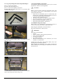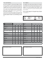
1
Instructions for Use Groove .EMS User Information Intended use power wheel chairs: Use Power wheelchairs are exclusively for a user who is unable to walk or has limited mobility, for their own personal use in- and outdoor. When an Attendant Control Module is fitted, the Power Wheelchair may be operated by an assistant on behalf of the user. When a Dual Control Module is fitted the Power Wheelchair may be operated by the user, or control may be switched to an assistant to operate on behalf of the user. The maximum weight limit (includes both the user and any weight of accessories fitted to the wheelchair) is marked on the serial number label, which is affixed to the chassis of the chair. Warranty can only be taken on if the product is used under the specified conditions and for the intended purposes. The intended lifetime of the wheelchair is 5 years. Please DO NOT use or fit any 3rd party components to the wheelchair unless they are officially approved by Sunrise Medical. Sunrise Medical is ISO 9001 certified, which ensures quality at all stages of the development and production of this wheelchair. WARNING! DO NOT USE YOUR WHEELCHAIR UNTIL THIS MANUAL HAS BEEN READ AND UNDERSTOOD. Sunrise Medical declares under its sole responsibility that this product is in conformity with the requirements of the directive 93/42/EEC amended by 2007/47/ EEC.” Sunrise Medical declares that this product fulfils the performance requirements for a “Crash Test” to ISO 7176-19. Area of application The variety of fitting variants as well as the modular design mean that it can be used by those who cannot walk or have limited mobility e.g. because of: • Paralysis • Loss of extremity (leg amputation) • Extremity defect deformity • Joint contractures/joint injuries • Strokes and brain injuries • Neurological disabilities (e.g. MS, Parkinson…) • Illnesses such as heart and circulation deficiencies, disturbance of equilibrium or cachexia as well as for elderly people who still have the strength in the upper body. • Persons who are mentally and physically able to control an input device to operate the chair and its functions in a safe way. When considering provision, please also note the body size, weight including the distribution of body weight, the user’s physical and psychological constitution, the age of the user, their living conditions and their environment. If in doubt a health care professional should be involved to ensure the user is not exposed to unacceptable risks. Sunrise Medical is ISO 9001 certified, which ensures quality at all stages of the development and production of this wheelchair. 2 Quickie Groove .EMS 1.0 Your Wheelchair 6 6.0 Seating 2.0 How to use this manual 6 6.1 Firm seat board.......................................................... ��� 23 6.2 Seat cushions.............................................................. ��� 23 6.3 Changing seat depth on the standard rehab seat.... ��� 23 6.4 Changing seat height................................................. ��� 23 6.5 Removable seat covers............................................... ��� 23 6.6 Backrest removal and refitting (rehab & comfort seat).............................................. ��� 23 6.7 Optima backrest upholstery...................................... ��� 24 6.8 Manual adjustable backrest (manual recline)......... ��� 24 6.9 Manual angle adjustment of the fixed back............. ��� 24 6.10 JAY backrests........................................................... ��� 24 6.11 Headrest.................................................................... ��� 24 6.12 Manual setting of the seat angle on the Groove.... ��� 24 6.13 Powered Seating....................................................... ��� 24 2.1 Introduction................................................................ �������6 2.2 Guarantee................................................................... �������6 2.3 Warranty conditions.................................................. �������6 3.0 Label Explantation / Word definitions 7 3.1 Definitions of words used in this manual................. �������7 3.2 Label explanations..................................................... �������8 4.0 General safety warning and user tips 10 4.1 General warnings....................................................... �����10 4.2 Features and options.................................................. �����10 4.3 Kerbs........................................................................... �����10 4.4 Routine service........................................................... �����10 4.5 Emergency freewheel................................................. �����10 4.6 EMC - Radio transmitting devices........................... �����10 4.7 Emergency braking.................................................... �����10 4.8 Sharp turns................................................................. �����11 4.9 Batteries...................................................................... �����11 4.10 Tyres.......................................................................... �����11 4.11 Weight limit............................................................... �����11 4.12 Wheelchair motors................................................... �����11 4.13 Wheelchair range..................................................... �����12 4.14 Road use.................................................................... �����12 4.15 Adverse conditions................................................... �����12 4.16 Ramps....................................................................... �����12 4.17 Transfer to and from the chair................................ �����12 4.18 Lift and tilt modules................................................ �����12 4.19 Anti tips..................................................................... �����12 4.20 Use on a slope........................................................... �����13 4.21 Gradients: ascents.................................................... �����13 4.22 Gradients: descents.................................................. �����13 4.23 Using a vehicle mounted passenger lift.................. �����13 4.24 Creep mode............................................................... �����13 4.25 Stability of your wheelchair.................................... �����14 4.26 Seat stay.................................................................... �����14 4.27 Wheels....................................................................... �����14 4.28 Rear view mirror...................................................... �����14 4.29 Crutch holder........................................................... �����14 4.30 Lights and indicators............................................... �����15 4.31 Vent tray.................................................................... �����15 4.32 Swing away tray....................................................... �����15 4.33 Perfect fit seating...................................................... �����15 4.34 Using a kerb climber................................................ �����15 4.35 Lap strap................................................................... �����17 5.0 Preparing your wheelchair for use 18 5.1 Handling the wheelchair............................................ �����18 5.2 Preparation for transportation or storage............... �����18 5.3 Re-Assembling . ......................................................... �����18 5.4 Emergency freewheel................................................. �����18 5.5 Drive wheel suspension GROOVE F/R................... �����19 5.6 Control joystick unit position................................... �����19 5.7 Armrests...................................................................... �����19 5.8 Legrests....................................................................... �����20 23 7.0 The VR2 Hand Control Series 26 7.1 On/Off button:............................................................ ��� 26 7.2 Battery gauge:............................................................ ��� 26 7.3 Locking/unlocking the wheelchair:.......................... ��� 26 7.4 Operating the control joystick:................................. ��� 26 7.5 Maximum speed/profile indicator:........................... ��� 26 7.6 Speed/Profile decrease button:.................................. ��� 26 7.7 Speed/Profile increase button:.................................. ��� 26 7.8 Actuator button and LEDs:....................................... ��� 27 7.9 Charging and programming socket:........................ ��� 27 7.10 VR2-L........................................................................ ��� 27 7.11 Lights and indicators:.............................................. ��� 27 7.12 Indicators:................................................................. ��� 27 7.13 Main lights:............................................................... ��� 27 7.14 Hazard warning lights:............................................ ��� 27 7.15 Actuator button and LEDs:..................................... ��� 28 7.16 VR2 dual control unit.............................................. ��� 28 7.17 Maximum speed button and indicator:................. ��� 28 7.18 The horn button:...................................................... ��� 28 8.0 Troubleshooting Using The VR2 Hand Control 30 8.1 Self help guide............................................................ ��� 30 9.0 R-net Control System 31 9.1 R-net control system information............................. ��� 31 10.0 Controller Mounts 32 10.1 General warnings..................................................... ��� 32 10.2 Parallel swing-away general warnings, (Fig.9.1)... ��� 32 10.3 Attendant control, (Fig.9.2)..................................... ��� 32 10.4 Centre bar mount control (R-net).......................... ��� 33 10.5 Tray mount control (R-net)..................................... ��� 33 10.6 Swing-away tray mounted centre control (R-net). ��� 33 10.7 Forus control (R-net)............................................... ��� 33 10.8 Powered swing away arm (R-net)........................... ��� 34 .EMS Quickie Groove 3 11.0 Speciality Controls (R-net Omni Plus only) 35 14.0 Maintenance and Cleaning 11.1 Proximity head array............................................... ��� 35 11.2 Driving with the head array (Fig 9.1)..................... ��� 35 11.3 Proportional head control....................................... ��� 35 11.4 Wafer board, sip and puff control and buddy buttons........................................................... ��� 36 11.5 HMC mini joystick as a chin control or hand control.............................................................. ��� 36 11.6 Proportional chin control (Fig.11.9)....................... ��� 36 14.1 Tyre maintenance and pressures............................ ����51 14.2 Removing the MWD castor wheel......................... ����52 14.3 Removing the RWD/FWD castor wheel................ ����53 14.4 Cleaning and your wheelchair................................ ����54 14.5 Lighting bulb exchange procedure......................... ����55 14.6 Electrical connections.............................................. ����55 14.7 How to connect the cables to the batteries............. ����56 14.8 Controller access...................................................... ����57 14.9 Storage...................................................................... ����57 14.10 Authorised Sunrise Medical service agents......... ����57 14.11 Recommended maintenance routines................... ����57 14.12 Performance checks............................................... ����58 12.0 Batteries and charging 37 12.1 Batteries.................................................................... ��� 37 12.2 Safety cut-outs.......................................................... ��� 37 12.3 Common battery statements................................... ��� 37 12.4 General battery information................................... ��� 37 12.5 Maintenance free batteries...................................... ��� 38 12.6 Battery care.............................................................. ��� 38 12.7 Maintenance free battery care plan....................... ��� 38 12.8 General charger information.................................. ��� 38 12.9 Charger safety features........................................... ��� 38 12.10 Procedure for connecting the charger and charging........................................................... ��� 39 12.11 The range of your vehicle...................................... ��� 40 12.12 Battery warranty.................................................... ��� 40 13.0 Transportation 41 51 15.0 Specification sheets (EN 12184 & ISO 7176-15) 59 15.1 Model: Quickie Groove R ...................................... ����59 15.2 Model: Quickie Groove M ..................................... ����60 15.3 Model: Quickie Groove F ....................................... ����61 15.4 Model: Quickie Groove F-XL ................................ ����62 16.0 Service History 63 17.0 Disposal 63 18.0 GROOVE Battery Wiring Diagram 64 13.1 Transportation Warnings........................................ ��� 41 13.2 Occupant restraint instructions.............................. ��� 42 13.3 Transportation of the Groove wheelchair.............. ��� 42 13.4 The tie down label and placement.......................... ��� 42 13.5 Front wheel drive tie down label placement.......... ��� 43 13.6 Rear wheel drive tie down label placement........... ��� 43 13.7 Mid wheel drive tie down label placement............ ��� 44 13.8 Securing the wheelchair into the vehicle................ ��� 44 13.9 Front Wheel Drive Tie Downs................................ ��� 44 13.10 Rear Wheel Drive Tie Downs................................ ��� 45 13.11 Mid Wheel Drive Tie Downs................................. ��� 45 13.12 Groove transportation instructions ELR / ALR strap.................................................... ��� 45 13.13 Transit Kit Fitting Instruction / Front-tie down Brackets onto Perfect Fit Seating System / Kit P/N015605............................ ��� 46 13.14 Front Tie-down Brackets onto Rehab and Recaro Seating Systems – Kit P/N 015604........... ��� 47 13.15 Front Tie-down fixing position onto Comfort Seating Systems – Kit P/N 015544........................ ��� 48 13.16 Rear Tie-down Brackets onto all Groove Seat Interfaces – Kit P/N 015604, 015605 and 015544..................... ��� 49 13.17 Leg Strap Fitting Instructions Adjustable Hangers.................................................................... ��� 50 13.18 Special shipping requirements ..................................50 4 Quickie Groove .EMS Your Wheelchair Rear/Front Wheel Drive Armrest Backrest Controller Skirt Guard Cushion Legrest Suspension Footplate Drive wheel Castor Anti tips Please note that the front wheel drive has the same base unit but with the seating reversed Mid Wheel Drive Controller Backrest Armrest Legrest Skirt Guard Suspension Footplate Castor Drive wheel Castor .EMS Quickie Groove 5 1.0 Your Wheelchair We at Sunrise Medical want you to get the best out of your GROOVE wheelchair. This Owner’s Manual will familiarise you with the chair and its features. It contains hints on everyday usage and general care in addition to information on the high quality standards which we adhere to and details about the guarantee. Your wheelchair should be delivered fully configured for your use; there are a wide range of components and adjustments available on the GROOVE. For further information about these you should contact your Sunrise Medical authorised dealer. Your wheelchair will reach you in excellent condition having been personally inspected before leaving our factory. Following the guidelines for maintenance and cleaning your wheelchair will maintain its first class condition and give you complete satisfaction. The GROOVE has been designed for use by an individual on a daily basis. It is suitable for both indoor and outdoor use (Class B). It is only intended for use as a pavement vehicle, but may also be used when crossing between pavements. This vehicle has been designed for a single occupant of limited mobility who has the cognitive, physical and visual ability to control the vehicle safely. The Groove R, Groove F & Groove M have a maximum user weight up to 182Kg (dependant on options chosen for your chair). The Groove R & Groove M have a maximum slope handling of 18% (10°). The Groove F- XL, has an increased maximum user weight of 240Kg. The Groove F and Groove F-XL, has a maximum slope handling of 10%, (6°). If you are in any doubt as to the suitability of the power chair, contact your local Sunrise Medical approved supplier for clarification, prior to commencing use. It is very important to read the relevant section of the owner’s manual when making any minor adjustments. Consult the Technical Manual or your local Sunrise Medical authorised dealer for more complex adjustments. If you have any queries about the use, maintenance or safety of your wheelchair, please contact your local approved Sunrise Medical service agent. If you do not know of an approved dealer in your area or have any other questions please write or telephone: 2.0 How to use this manual 2.1 Introduction Please keep a note of your local service agent’s address and telephone number in the space below. In the event of a breakdown, contact them and try to give all relevant details so they can help you quickly. The wheelchairs shown and described in this manual may not be exactly the same in every detail as your own model. However, all instructions are still entirely relevant, irrespective of detail differences. NOTE: The manufacturer reserves the right to alter without notice any weights, measurements or other technical data shown in this manual. All figures, measurements and capacities shown in this manual are approximate and do not constitute specifications. 2.2 Guarantee The guarantee form is included in the Sunrise Pack. Please fill in the relevant details and return to us to register your entitlement. THIS IN NO WAY AFFECTS YOUR STATUTORY RIGHTS. 2.3 Warranty conditions 1) The repair or replacement will be carried out by an authorised Sunrise Medical dealer/service agent. 2) To apply the warranty conditions, should your wheelchair require attention under these arrangements, notify the designated Sunrise Medical service agent immediately giving full information about the nature of the difficulty. Should you be operating the wheelchair away from the locality of the designated Sunrise Medical service agent, work under the “Warranty Conditions” will be carried out by any other service agent designated by the manufacturer. 3) Should any part of the wheelchair require repair or replacement, as a result of a specific manufacturing or material defect, within twenty four months from the date on which the possession of the wheelchair was transferred to the original purchaser, and subject to it remaining within that ownership, the part or parts will be repaired or replaced completely free of charge if returned to the authorised service agent. Sunrise Medical LTD. Sunrise Business Park High Street, Wollaston West Midlands DY8 4PS England Phone: +44 (0) 1384 44 66 88 Fax: +44 (0) 1384 44 66 99 Dealer signature and stamp 6 Quickie Groove .EMS 4) Any repaired or replaced part will benefit from these arrangements for the balance of the warranty period applicable to the wheelchair. 5) Parts replaced after the original warranty has expired are covered for a further twelve months. 6) Items of a consumable nature will not generally be covered during the normal warranty period, unless such items have clearly suffered undue wear as a direct result of an original manufacturing defect. These items include amongst others upholstery, tyres, inner tubes and similar parts. On powered products this will also include batteries, motor brushes etc 7) The above warranty conditions apply to all wheelchair parts for models purchased at full retail price. 8) Under normal circumstances, no responsibility will be accepted where the wheelchair has required repair or replacement as a direct result of: a) The wheelchair or part not having been maintained or serviced in accordance with the manufacturer’s recommendations, as stated in the Owner’s Manual and/or Service Manual. Or failing to use only the specified original equipment parts. b) The wheelchair or part having been damaged by neglect, accident or improper use. c) The wheelchair or part having been altered from the manufacturer’s specifications, or repairs having been attempted prior to the service agent being notified. 3.0 Label Explantation / Word definitions 3.1 Definitions of words used in this manual Word Definition DANGER! Advice to the user of Potential Risk of serious injury or death if the advice is not followed WARNING! Advice to the user of a potential risk of injury if the advice is not followed CAUTION! Advice to user that potential damage to equipment may occur if the advice is not followed NOTE: General advice or best practice RWD Rear Wheel Drive FWD Front Wheel Drive MWD Mid Wheel Drive .EMS Quickie Groove 7 3.2 Label explanations Labels and their descriptions 8 Warning - Do Not Touch - HOT WARNING – Ensure the seat interface quick release is screwed in tight before using your wheelchair, especially on a slope WARNING – Do Not Touch - Static may damage equipment WARNING – Maximum user weight for the chair (will be either 240Kg, 182Kg or 137Kg depending on the options, seating and model chosen) WARNING – Danger of finger entrapment WARNING – When the seat is raised you must always use the seat stay Indicates battery charge point Location of 70Amp circuit breaker Quickie Groove .EMS Labels and their descriptions WARNING! • • • • • • BATTERIES CONTAIN ACID AND CAN EXPLODE. ALWAYS WEAR EYE PROTECTION WHEN WORKING WITH BATTERIES. ALWAYS KEEP BATTERY TERMINALS AND CLAMPS CLEAN AND FREE OF CORROSION. ALWAYS CHARGE BATTERIES IN WELL VENTILATED AREAS, AWAY FROM SPARKS AND FLAME. NEVER ALTER BATTERY WIRING OR BATTERY BOX. NEVER ALLOW TOOLS TO MAKE CONTACT ACROSS TERMINALS. NEVER USE BATTERIES OR CLAMPS WITH WING NUT TERMINALS, OR CLAMPS THAT EXCEED TERMINAL POST HEIGHT. Battery Label – Warning Instructions and Circuit Diagram For Rear and Front wheel drive chairs only: Lever position for the freewheel mechanism. Down – disengaged Up - engaged Shows the direction of the front of the chair For Mid wheel drive chairs only: Lever position for the freewheel mechanism. Out – disengaged In - engaged Attached to Joystick WARNING – Do not drive your wheelchair on a slope with the backrest reclined and/or the seat lifted Actuator labels Right Legrest Left Legrest Seat Tilt Backrest Recline Seat Lift RWD/FWD - Do not disengage free wheel whilst on a slope MWD - Do not disengage free wheel whilst on a slope .EMS Quickie Groove 9 4.0 General safety warning and user tips 4.1 General warnings WARNING! • • • • • Always ensure that your wheelchair is switched off before attempting to mount or dismount. Always ensure that you are able to operate all controls from a comfortable position. Paying attention to your posture is essential to ensure your continued comfort and well being. Always make sure that you can be seen clearly, especially if you intend using your wheelchair in poor light. This wheelchair has been built to match the needs of a particular user. If used by another user then it may need to be adjusted and reprogrammed. Do not let children or others use your wheelchair. 4.2 Features and options NOTE: Some of the options shown in this manual may not be available in your country and may also restrict the overall physical limits of the standard product (e.g. max. speed, user weight limit, etc.). Those limitations are marked on the order form, in the technical manual and in this owner’s manual. For further information please consult your Sunrise Medical authorised dealer. 4.3 Kerbs DANGER! Never descend a kerb Forwards with a RWD chair or Backwards with a FWD and MWD chair. Please read carefully the section 4.34 on kerb climbing in this manual before attempting to mount and dismount any kerbs in your wheelchair. Do not attempt to climb or descend a series of steps. It is unsafe to do so and could cause personal injury or damage the chair. The Groove has only been designed to climb a single step or kerb. We recommend that users with upper trunk instability wear further customised restraint systems to keep the upright body position during decending or ascending ramps, curbs or obstacles. 4.4 Routine service The recommended service interval is one year. (See service history table in section 16). 4.5 Emergency freewheel DANGER! Please remember that you have no braking facility when the freewheel levers are moved from the normal drive position to the freewheel position (Fig. 4.1 and Fig. 4.2). Always ensure an attendant is with you when bringing the chair into the freewheel mode. The wheelchair must never be left with one or both levers in the freewheel position. For an enhanced description of this facility and its limitations to use please see later section at 5.4. Fig. 4.2 Fig. 4.1 4.6 EMC - Radio transmitting devices. WARNING! When operating two-way radio, walkie-talkies, C.B., amateur radio, public mobile radio and other powerful transmitting devices the wheelchair should be brought to a halt and turned off. The operation of cordless, mobile telephones and cell phones including hands-free devices is permitted but if abnormal operation of the wheelchair is encountered then the chair must be brought immediately to a halt and turned off. NOTE: the electrical systems of the wheelchair may disturb the performance of alarm systems in retail shops. 4.7 Emergency braking There are three ways to stop your wheelchair: 1. Simplest and safest way to stop the wheelchair is to release the joystick (see Hand Control section 7). This will bring the chair to a halt in a controlled manner. 2. Pulling back the joystick will brake the chair abruptly with a fast stop 3. Switching the control system off whilst the chair is in motion will also bring the chair to a halt. WARNING! This third method is only to be used in an emergency situation as the stopping action is very abrupt. 10 Quickie Groove .EMS 4.8 Sharp turns 4.11 Weight limit DANGER! Full speed turns should not be attempted. If you need to turn sharply you must reduce your speed with the joystick or speed setting. This is particularly important when travelling across or down a slope. Disregarding this advice could lead to your wheelchair tipping over. 4.9 Batteries Your wheelchair is supplied as standard from Sunrise Medical with maintenance-free batteries. These only require regular charging. Before charging, please read section 12 in this manual. WARNING! DANGER! • The user plus items carried should never exceed a total weight of 182Kg or 137Kg if fitted with a Perfect Fit powered recline or kerb climber. This figure rises to 240Kg for the Groove F-XL. • Never use this chair for weight training if the total weight (user plus additional weights) exceed a total weight of 182Kg or 137Kg if fitted with a Perfect Fit powered recline or kerb climber, (240Kg for the Groove F-XL). • Exceeding the weight limit is likely to damage the seat, frame or fasteners and may cause severe injury to you or others from chair failure • Exceeding the weight limit will void the warranty. 4.12 Wheelchair motors After prolonged use, the motors will produce heat, which is radiated through the motors’ outer casing. Do not, under any circumstances, tamper with the batteries. If in any doubt contact your local Sunrise Medical authorised dealer. CAUTION! Before using your vehicle for the very first time, please charge your batteries for a period of 24 hours. WARNING! Do not touch the motors’ outer casing for at least 30 minutes after using the wheelchair, to allow it to cool. (Fig. 4.4 and Fig. 4.5). Fig. 4.4 Fig. 4.5 WARNING! Avoid contact with acid on damaged sealed type batteries or wet batteries. Battery acid can cause burns to the skin as well as damage to floors, furniture and your wheelchair. If it comes into contact with the skin or clothing, wash immediately with soap and water. If it comes into contact with the eye, immediately flood the eye with running cold water for at least 10 minutes and seek medical attention immediately. Acid can be neutralised with baking soda and water. Take care to keep batteries upright at all times, especially when transporting your wheelchair. Battery and charger type: 24V (2x12V) / 73 Ah/20h. Maintenance free Dimensions: 260 x 171 x 210 mm. 24V (2x12V) / 60 Ah/20h. Maintenance free Dimensions: 256 x 169 x 178 mm. Connector: 3 pins “Neutrik” type (polarity scheme in section 17) WARNING! Hot surfaces Not only the motors can get hot during the operation of the chair, but also the upholstery material and armrests when standing in the sun. 4.10 Tyres Your wheelchair tyres can wear depending on use. Check them regularly in accordance with the service instructions in this manual, especially the pressure of the tyres. DANGER! Never inflate the tyres using a garage forecourt airline, always use the pump provided. .EMS Quickie Groove 11 4.13 Wheelchair range The range of your wheelchair can be affected by many factors such as user weight, terrain, ambient temperature, use of powered options and battery condition. NOTE: The stated range in the sales literature should be seen as the theoretical maximum (ISO 7176; Part 4) and may not be attained by every user (also see section 11.12. in this manual). We recommend that every user initially limit their journey to half the stated range, until they have confidence in the actual range their wheelchair can attain. CAUTION! If your battery indicator is showing a low charge then do not attempt a long journey unless you are confident in reaching your destination and also returning to your home without the risk of being left stranded. 4.14 Road use Please show the utmost consideration for the other traffic on the road. DANGER! Remember that the last thing a car or lorry driver expects to see is a wheelchair backing off the kerb into the road. If in any doubt, do not risk crossing the road until you are certain that it is safe. Always cross the road as quickly as possible; there may be other traffic. 4.15 Adverse conditions Please be aware that when driving your wheelchair in adverse conditions, e.g. on wet grass, mud, ice, snow or other slippery surfaces, you may experience a reduction in the grip and traction of your wheelchair. WARNING! We recommend you take extra precautions in these conditions, particularly on hills and slopes; your wheelchair could become unstable or skid causing possible injury. NOTE: Extreme variances in temperature may trigger the self protect mechanism in the control system. If this occurs the control system will temporarily shut down to prevent damage to the electronics or the chair. 4.16 Ramps WARNING! When using a ramp, please ensure that it is capable of taking the combined weight of the power chair and yourself. If a ramp is being used to load a chair into a vehicle, please ensure the ramp is properly secured to the vehicle. Always approach the ramp head-on and exercise caution. CAUTION! Please ensure your ramp is suitable for the product you are transporting. 4.17 Transfer to and from the chair WARNING! Sunrise Medical recommend that you consult your healthcare professional for assistance in developing your personal front or side transfer technique to best suit your needs and avoid any personal injury. WARNING! Ensure controller is switched off during transfers to avoid unintentional movement. 4.18 Lift and tilt modules WARNING! Please be aware that the lift and tilt modules present a trap hazard. Make sure that when operating the tilt and lift it is free from all clothing, hands, feet and other extremities to prevent injury. Do not drive on ramps or slopes with the seat tilted, reclined or raised. Before attempting to climb or decline a slope, return to an upright position 4.19 Anti tips CAUTION! Make sure that anti tips are not damaged or worn before using your chair. Check the anti tips are functioning correctly on a regular basis. WARNING! Attendants must be aware of the location of the RWD anti tips to prevent feet being trapped underneath causing injury Attendants - Do not stand on the anti tips, this could cause the wheelchair to become unstable. 12 Quickie Groove .EMS 4.20 Use on a slope Your wheelchair has been designed and tested to allow its use on slopes or gradients of up to 10° (18%) in RWD/ MWD configuration and 6° (11%) in FWD conFiguration. However, you have the option of adjusting your seating position with either a lift, tilt or recline or a combination of these options. WARNING! In certain circumstances your wheelchair could become unstable. Before attempting to climb or descend a slope or a kerb, caution should be taken when using weight shift options (e.g. powered tilt or recline), of the seat and/or your body for a counter balance weight. To improve stability lean forward when driving uphill, with the seat and back in an upright position. Alternatively sit in an upright position when travelling in a forward, downhill direction or tilt and/or recline the seat backwards. When driving downhill with a FWD chair reduce your speed below 5kph. This prevents the chair from going onto the front anti-tip wheels when decelerating. WARNING! We strongly recommend that you return the seat and back to an upright lowered position before attempting to climb or descend a slope. Failure to do this may cause the wheelchair to become unstable. WARNING! If you are in any doubt about the capabilities of your wheelchair on a slope then do not attempt to drive up or down the slope/ kerb; try to find an alternative route. 4.21 Gradients: ascents WARNING! • • • • When going uphill, keep the chair moving. Steer by carefully moving the joystick forwards making slight Left and Right adjustments as you go. If you have stopped on a hill, you should start slowly. On a RWD chair, if necessary lean forward to prevent the tendency for the front wheels to lift. 4.22 Gradients: descents On descents, it is important not to let the wheelchair accelerate beyond its normal level of ground speed. WARNING! Proceed slowly down steep descents, (below the speed of 5kph) and stop if any anxiety arises regarding directional control. If the chair picks up speed, centre the joystick to slow it or to stop all forward movement, then restart slowly and do not allow the speed to increase. NOTE: The solid state controller has the benefit of a logic system that will help compensate when driving along a camber or up a hill. This is an added safety feature on your wheelchair. In addition of course, you may control the wheelchair speed by using the speed control. 4.23 Using a vehicle mounted passenger lift Wheelchair lifts are used in vans, buses and buildings to help you move from one level to another. DANGER! • • • • • Ensure that the user and all carers fully understand the lift manufacturer’s instructions for using the passenger lift. Never exceed the lift manufacturer’s recommended safe working load and load distribution guidance. Always turn off all power when you are on the lift. If you fail to do so, you may touch the joystick by accident and cause your chair to drive off the platform. Be aware that a rollstop at the end of the platform may not prevent this. Always position the user securely in the chair to help avoid falls while on the lift. Always ensure the chair is in drive mode when using passenger lift (wheels locked not in freewheel mode). 4.24 Creep mode WARNING! Please ensure your backrest recline angle relative to floor level, (which is a combination of the back recline itself and the tilt angle), does not exceed 12° to drive the chair safely. NOTE: If your backrest to level floor angle exceeds this limit the chair will automatically convert into “creep mode” which will allow you a maximum of 10% of the speed programmed in the profile. NOTE: If your wheelchair is fitted with a Lift/Tilt module, you will go into ‘Creep Mode’ as soon as the seat is lifted. NOTE: If your leg rest and recline actuators are used simultaneously, then you will go into ‘Creep Mode’ . WARNING! If you have Recaro seating or a manual recline backrest on your wheelchair, please be aware that there will be no feedback system to the controller that tells it that the seat is in a reclined position. If you recline your backrest and attempt to drive, it will not go into ‘creep mode’, it will instead drive at full speed. DANGER! This is especially dangerous when attempting to drive up a slope. .EMS Quickie Groove 13 4.25 Stability of your wheelchair Please follow the user instructions in this manual regarding the use of seat lift and tilt modules and the use of your chair on a slope. WARNING! Other variables can affect your chair stability, including: • • • Movement of the user Effects of the addition of accessories or other equipment Inappropriate adjustments or modifications to the wheelchair 4.27.1 Pneumatic Tyres with OKO fluid. WARNING! The OKO fluid is only meant as a temporary repair to the tyre. It must be replaced or repaired as soon as possible. The OKO fluid is classified as non hazardous but may cause irritation to the skin with prolonged contact. NOTE: First Aid measures for OKO fluid • Skin - Wash skin with plenty of water In some cases these issues are further compounded by the effects of the local environment such as: • Eyes - Immediately flood the eye with plenty of water for at least 5 minutes holding the eye open. • • • • • • Ingestion - Drink lots of water - Seek medical attention immediately. Hills Slopes Ramps Sloping pavements Dropped kerbs Furthermore different body proportions of a wheelchair user affect stability for example: • • • • Lower limb wasting or amputation Increased upper torso mass Upper torso height Obesity 4.26 Seat stay A seat stay is provided on your powerchair to provide access for service and maintenance. WARNING: Do not move the wheelchair with the seat stay in place and make sure you are on flat stable ground. Make sure that the plastic cap is securely fitted over the seat height tube. 4.28 Rear view mirror WARNING! To avoid injury to people around you please be aware that the mirror protrudes outside the space envelope of the chair and could cause injury to someone when driving past. The mirror must be used on the 10KPH model on UK roads. Always make sure that when using the mirror that it is clean and unbroken so that it does not impair your visibility. 4.29 Crutch holder WARNING! • • 4.27 Wheels DANGER! • • • • • • • 14 Always use the pump that is supplied with the chair, Never use a forecourt pump. Inspect all tyres regularly for signs of wear. Do not drive over anything that could cause punctures in the tyres. Ensure that there are no objects in your path that could possibly become lodged in your chair mechanism or in the spokes of the rear wheels. This could cause the chair to come to a sudden stop. Riding over drains or grids could cause the wheelchair castors or wheels to become lodged, causing the chair to come to a sudden stop. Always maintain the correct pressure for the tyre. These are listed in section 13 of this manual. Quickie Groove • • • Make sure that the crutch is securely fastened to the crutch holder. Make sure that the crutch is not interfering with the mechanisms of the chair. Make sure that the crutch does not protrude from the chair. Do not attempt to remove the crutch whilst the chair is in motion. Always come to a complete stop and turn off the power to the controls before attempting to remove the crutch. This will avoid accidentally operating the chair. .EMS 4.30 Lights and indicators 4.34 Using a kerb climber WARNING! Ensure that the lights and indicators are functioning correctly and lens are clean before going outdoors at night. Lights assembly can become very hot - Care must be taken if removing them for repair. 4.31 Vent tray WARNING! Always approach a kerb at 90° (Fig 4.6 and Fig 4.7) • Approach the kerb (step) head on driving forwards slowly and steadily and always at a 90° angle. • RWD-Chair: As the kerb climber or castor makes contact with the kerb (step), the wheelchair should be moving slowly. Small kerbs can be climbed from a standstill. FWD-Chair: Start accelerating the chair after a stop app. 20cm in front of the kerb to create enough speed/torque to get the chair up. MWD-Chair: Stop the chair as soon as the castor wheels touch the kerb. • RWD- and MWD-Chair: Apply sufficient power to the motors to lift the front of the chair up onto the kerb (step) and then apply slightly more power and speed so that the drive wheels climb the kerb (step) smoothly and without hesitation. As far as possible, keep the joystick in the straight forward position. FWD-Chair: slow down the acceleration as soon as the drive wheels are on the kerb until the rear castor are up. • In accordance to the ground clearance, the maximum obstacle height possible to climb is 5 cm for a RWDChair (10 cm with kerb climber on a rear wheel drive base, Fig. 4.9) and 10 cm for a FWD- and MWD chair, when conducted as described above. WARNING! Using a vent tray will affect the stability and overall weight of your wheelchair. • • • • • • Make sure that the batteries and the ventilator are securely fastened to the tray before use. Familiarise yourself with the increased size of the wheelchair before driving to prevent potential collisons When activating the recline backrest make sure that the area around the vent tray is clear. Be aware that the vent tray assembly can cause a finger trap hazard when the backrest is reclined. The vent tray is not designed to hold anything other than the vent unit and its batteries, it is not designed to hold an oxygen bottle etc. Use of these items may cause your wheelchair to become unstable. The vent tray must be installed and maintained by a Sunrise Medical authorised dealer. 4.32 Swing away tray WARNING! • • • • The maximum weight allowed for the tray is 2.5kg. Do not overload the tray, this could cause the tray to break or could cause the chair to become unstable. Do not leave lit cigarettes or other heat sources on the tray as this could cause the tray to deform and mark. Ensure that all extremities and clothing are free when positioning the tray for use. 4.33 Perfect fit seating WARNING! The approach speed and process can vary depending on your wheelchair drive type and castor wheel choice. WARNING! If you have Perfect fit seating, a recline armrest and lateral supports, please be aware that it is possible to fit the lateral supports in a position that could cause a pinch point between the supports and armrest. .EMS Quickie Groove 15 4.34.1 Dismounting the kerb with a rear wheel drive chair • WARNING! • • Reverse the chair slowly and carefully until both rear wheels are on the edge of the kerb, again in a 90° position to the kerb. • Reverse as slowly as possible off the kerb with the rear wheels. You will feel more secure if you can lean forward, but if you can’t, don’t worry, the wheelchair is extremely stable. As long as you stay within its limitation, you will be quite safe. • The front of the chair will naturally follow down the kerb as you continue to drive slowly backwards. We recommend to use the lap strap to feel more secure during declining the kerb. 4.34.2 Dismounting the kerb with a front (FWD) or mid wheel drive (MWD) chair WARNING! • Hold the kerb climber with your right hand in the receiver bracket. Align the holes of the receiver bracket and the kerb climber tube and plug in the locking pin from the top. Reverse the procedure to remove the kerb climber. DANGER! 1. Please show the utmost consideration for the other traffic on the road. Remember that the last thing a car or lorry driver expects to see is a wheelchair backing off the kerb into the road. If in any doubt, do not risk crossing the road until you are certain that it is safe. 2. Always cross the road as quickly as possible; there may be other traffic. 3. Do not attempt to go up or down more than a 10 cm (4”) high kerb (GROOVE R only with kerb climber fitted). 4. Do not attempt to use the kerb climber on a series of steps. 5. Do not attempt kerbs if on steep slopes or cambers. • Move the chair slowly and carefully in a forward direction until both front wheels are on the edge of the kerb, again in a 90° position to the kerb. (Fig 4.6 ) 6. Do not attempt any kerbs in the vicinity of drain covers, uneven or gritty road surfaces. • Drive as slowly as possible off the kerb with the drive wheels. Don’t stop the chair during declining the kerb. You will feel more secure if you can lean backwards, but if you can’t, don’t worry, the wheelchair is extremely stable. As long as you stay within its limitation, you will be quite safe. 7. Do not attempt to dismount a kerb any higher than 5 cm (2”) in the forwards direction in a RWD-chair. • The rear of the chair will naturally follow down the kerb as you continue to drive slowly forwards. • All powered seating options need to be in home position. Your powered legrests may need to be adjusted to give enough clearance to mount or dismount the kerb. • We recommend to use the lap strap to feel more secure during declining the kerb. For extra protection we recommend to fit every chair with the legrests. 8. Do not mount or dismount kerbs at an angle other than straight on (90 degrees) to the edge of the kerb. 9. Prior to climbing ensure your legrests will clear the kerb. 10. Take care of the anti tips which might interfere with the kerb or the ground when mounting or dismounting a kerb. WARNING! This wheelchair is designed to be repaired and assembled by a Sunrise Medical authorised dealer and not the end user. The end user has to disassemble and assemble the chair only for transportation (see section 5.2). 4.34.3 Kerb climber fitting and removal procedure (RWD base only) • Locate the kerb climber bar into the left hand location bracket and push it into the right hand receiver bracket (Fig. 4.8 and Fig 4.9). Fig.4.8 16 Quickie Groove Fig.4.9 .EMS 4.35 Lap strap The 5 cm (2“) Aircraft Buckle lap strap. (Fig. 4.10). The 5 cm (2”) Aircraft Padded Lap strap. (Fig. 4.11) The lap strap fitted for a righthanded user. (Fig. 4.12) The lap strap fitted for a lefthanded user. (Fig. 4.13) Place the strap loosely across the seat with the opening end of the buckle facing to the right for a left-handed person and to the left for a right-handed person. (Fig. 4.14) Fig. Fig.4.11 Fig. 4.12 Fig. 4.13 Fig. 4.14 Pass the other ends of the strap through the gap between the backrest posts and the backrest upholstery as shown above. (Fig. 4.15) Fig. 4.15 Feed the bracket ends of the straps under the backrest brace bar as shown. Ensure that the adjuster buckles can be accessed and the strap is not twisted. (Fig. 4.16) Fig.4.16 Pass the bolt through the plain washer and strap bracket. (Fig. 4.17) Fig. 4.17 Place a saddle washer on the bolt (Fig. 4.18). Pass the bolt through the seat frame. Mount as shown above for the 36-46cm, (14”-18”), seat depth. Mount the bolt the other way round, with the head on the inside, for seat depths greater than 51cm, (20”), to avoid a clash with the back post bracket (Fig. 4.19) Place the other saddle washer on the end of the bolt and against the frame. Fit the plain washer and nut. Tighten using a 4.0mm Allen key and 10.0mm spanner (Fig. 4.20). Adjust the lap strap to suit, leaving no more than a hand’s width gap for comfort and safety. (Fig. 4.21). The hand clearance should be tight and not allow large gaps. Fig.4.18 Fig. 4.19 Fig.4.20 Fig. 4.21 Fig.4.22 Generally, the lap strap should be fixed so that the straps sit at an angle of approximately 45° (Fig. 4.22), and when correctly adjusted should not allow user to slip down in the seat. DANGER! • Always make sure that the lap strap is correctly secured and adjusted prior to use. • Too loose a strap could cause the user to slip down and cause serious injury. • Check lap strap and securing components at regular intervals for any signs of fray or damage. Replace if necessary • When servicing, check for correct operation of the release buckle and for any signs of wear on the material or plastic brackets NOTES: 1. Standard Sling - Lap strap movement is restricted by upholstery 2. Contoured back - Use universal bottom bracket as per recline back method .EMS Quickie Groove 17 5.0 Preparing your wheelchair for use Fig. 5.3 Fig. 5.4 5.1 Handling the wheelchair NOTE: To dismantle the chair for transport or storage no tools are required. List of components when dismantled (components below are related to the maximum detachable parts and dependent on the type of seating system chosen): 1 pair of armrests 1 pair of legrests, or single centre mount legrest with flip-up footplate 1 backrest (Std. Rehab/comfort seat only) 1 drive unit with seat frame. 5.2 Preparation for transportation or storage First remove the legrests if swing away legrests are Fig. 5.1 attached. In the case of a centre mount leg rest, just flip up the footboard. Lift off the armrests (Fig. 5.1), disconnect the hand control if necessary. Release and lift off or fold down the backrest at the frame (Fig. 5.2). Now you can store the chassis Fig. 5.2 part. By releasing the freewheel mechanism (Fig. 5.5 and Fig. 5.6) on the left and right side of the chassis you can move the drive unit as close as possible to the place you want to store it. You can also drive the base with the joystick up or down a ramp into and out of a car for transportation. WARNING! Make sure, when the chair is stored or left in the car or anywhere else, the controller is switched off and the freewheel mechanisms are engaged. CAUTION! 5.3 Re-Assembling Flip up or replace the backrest. Put your armrests back in and connect the remote controller. Attach the hangers or flip down the footplate. Make sure your freewheel mechanisms are engaged. Now you are ready to drive the chair. WARNING! Never lift the wheelchair by the armrests or the legrests, since they are detachable and harm could be done to the user or to the wheelchair. 5.4 Emergency freewheel Fig. 5.5 Fig. 5.6 GROOVE F/R By pressing and turning the release levers on both sides of the base into the down position (Fig. 5.5) the drives become disconnected from the motors. GROOVE M By releasing the locking lever and pulling the freewheel lever backwards on both sides of the base (Fig. 5.6) the drives become disconnected from the motors. DANGER! This may only be used in an emergency, or if you need to manually push your wheelchair. It is not intended for permanent use or to push the wheelchair up/down a slope with the user sitting in it. If there is a need to lift the drive unit on the RWD and FWD chair the big side frame tubes should be used. On the MWD use the rear castor arm and the drive wheel. Caution should be taken if the chair is in freewheel. NOTE: The chair’s automatic braking system will not work unless the brake release levers are in the “drive” position. To remove the control pod; VR2: Loosen the adjustment screw on the control arm and slide the arm out of the bracket, (Fig 5.3). Place the controller and arm in a safe place until required. R-net: Locate the in-line bus connector. Gently pull the plugs apart to separate the loom, (Fig. 5.4). To reconnect the hand control just repeat the process in reverse. Motor surfaces can be hot after use. Be careful not to touch the motor casing when disengaging the freewheel. 18 Quickie Groove WARNING! WARNING! Never attempt to disengage the freewheel mechanism whilst sitting on a slope. .EMS 5.5 Drive wheel suspension GROOVE F/R The GROOVE F/R has an effective and adjustable drive wheel suspension system as a standard feature. To match your requirements on drive comfort, the tension of the springs at the damper can be adjusted. Turning the aluminium ring on the bottom of the spring downwards will soften your ride, adjusting the aluminium ring in a higher position will harden it. This option is to be used to match the different user weights to the suspension system. (Fig. 5.7). We recommend the suspension adjustments are done equally on the left and right side of the chair. Fig. 5.7 5.7.2 Armrests-replacment Please refer to your appropriate armrest type. Single Post Armrest (Comfort, Rehab and Recaro Seat): Place the armrest tube in the armrest receiver. Fix and tighten it with the handle screw on the side of the armrest receiver (Fig. 5.8). Flip-back armrest (Perfect Fit seat): Flip the armrest all the way down until it sits on its mechanical stop. Guide it in its downward movement and do not let it fall on its own. Reclining armrest (Perfect Fit Seat): If you have taken it fully out, fit the rear stem into the round receiver at the back rest. Then lower the armrest and guide the front tube until it locks into the retaining tube. Lock it with the quick release mechanism (Fig. 5.9). 5.6 Control joystick unit position Depending on your chosen control system, there are two principles of control systems: Quickie VR2 and Quickie R-net controls (for details please see the controls section 7). The remote is mounted on a sliding mechanism which enables the control to be moved forwards and backwards. When the most comfortable position has been selected, secure the slider by tightening the locking screw. Ensure the locking screw is fully tightened prior to use and especially when transporting your wheelchair. 5.7 Armrests 5.7.1 Armrests-removing The armrests on both sides of the wheelchair can be moved to allow side transfer. (For hand control removal see section 5.6) Please refer to your appropriate armrest type. 5.7.3 Adjusting the armrest width (Recaro, Rehab and Comfort Seat only) To adjust the width loosen the Fig. 5.10 two screws (10mm spanner) as shown in (Fig. 5.10) move the armrest receiver brackets to the desired position and tighten the screws firmly prior to use. The steel part must always be located in both aluminium clamp halves Single Post Armrest (Comfort, Rehab and Recaro Seat): Release the handle screw on the side of the armrest receiver and remove armrest (Fig. 5.8). Flip-back armrest (Perfect Fit seat): For side transfer flip the armrest all the way up until it goes into its mechanical stop. This frees your space for side transfer. Reclining armrest (Perfect Fit Seat): Unlock the quick release mechanism at the bottom front pivot of the armrest. Lift the armrest off the receiver. You can now turn it to the outside, flip it backwards or release the rear part of the armrest to take it fully off (Fig. 5.9). Fig. 5.8 Fig. 5.9 .EMS Quickie Groove 19 5.7.4 Adjusting armrest height Please refer to your appropriate armrest type. Single Post Armrest (Comfort, Rehab and Recaro Seat): The height adjustment of the armrests is made via the threaded screws at the upper edge of the insertion tube of the side guard. To adjust the height, (Fig. 5.11) loosen the adjusting screw (6 mm Allen Key), move the armrest to the desired position and tighten the screw. Fig.5.11 Flip-back armrest (Perfect Fit Fig.5.12 seat): Take the back cover off the Perfect Fit backrest. Loosen the two bolts of the armrest receiver and adjust the height along the slot, (Fig. 5.12). Tighten the screws carefully when the appropriate height is achieved. The adjustment range is also increased by turning the receiver part upside down. Reclining armrest (Perfect Fit Fig.5.13 Seat): Loosen the two screws at the rear armrest receiver and slide the armrest up and down along the slot in the backrest wing, (Fig. 5.13). Fix it with the screws at the appropriate height. Take the two screws out at the front tube of the reclining armrest to adjust the front height. Hold the outer tube at the appropriate height, replace the screws and re-tighten. 5.8.1 Fitting legrest Offer the legrest assembly at right angles to the frame (Fig. 5.14 and 5.15), locate the stem into the legrest and swing the assembly forward as in Fig. 5.14 to lock in position. To swing away the footrest, depress the retaining catch and turn the footrest out. This can now be lifted out if required. Fig.5.14 Fig.5.15 5.8.2 Footplates The footplates may be flipped up to aid entry and exit from the chair. WARNING! Do not use the footplates to stand on as the full weight of your body may cause the chair to tip forwards. This could result in injury and could damage the footrests. 5.8.3 Adjusting the footrest length To adjust the footrest length remove the screw assembly on the footrest stem as shown in (Fig. 5.16 and 5.17), adjust the length to suit. Ensure the bolt is firmly located and tightened prior to use. Fig. 5.16 Fig. 5.17 5.8 Legrests WARNING! Be aware of your environment to make sure you do not injure your legs when legrests are extended. NOTE: The internal footrest stem may require cutting down in length to allow the footplate position to be raised. WARNING! Always ensure that the legrests or footplates do not come into contact with the castors before driving the wheelchair. WARNING! Legrests are not to be used for lifting or carrying the wheelchair with an occupant. 20 Quickie Groove .EMS Fig. 5.18 5.8.4 Manual/Articulating elevating legrest (ALR/ELR) To elevate: Pull the legrest upwards and stop at the desired height. The legrest will automatically lock in the chosen position. To lower: Push the release lever slowly forward. The legrest will lower the angle. As soon as you release the lever, the legrest will be locked in the current position. WARNING! Keep hands clear of the adjustment mechanism between the frame and the movable parts of the legrest while elevating or lowering the legrest. NOTE: Please refer to Section 7 for details of your controls 5.8.5 Powered elevating or articulating leg rest NOTE: Both legrests can also be operated simultaneously. To operate a powered leg rest: VR2 Control: The actuator buttons can operate any factory approved actuator. Operation is dependent on what options are fitted to your wheelchair, (Fig.5.18). To operate the legrests, seat tilt, seat lift or backrest recline. • Push one of the actuator buttons that has the seat icon on it to select actuator mode. • Operate the joystick left or right to select the actuator required (actuator 1 or actuator 2). Selection is indicated via the lighting of the red LED adjacent to the desired actuator button. • Operate the joystick in the forward or rearward direction to move the leg rest/seat lift/tilt or recline up or down. • Release the joystick when the desired angle is reached. • To return to drive mode press the actuator button again. CAUTION! Once the leg rest is fully lifted or in its lowest position do not hold the joystick in its operating position as this could damage the actuator.. R-net Control Please refer to your R-net Owner’s Manual for details. .EMS Quickie Groove 21 5.8.6 Powered centre mount leg rest WARNING! There is an option on the programme of the leg rest that allows you to send the footrest to the floor to allow for easier mounting and dismounting for the user. Be aware that when powered the area around and underneath the footplate needs to be clear of all personal items and bodily extremities to prevent injury or damage to property. CAUTION! Once the leg rest is fully lifted or in its lowest position do not hold the joystick in its operating position as this could damage the actuator. Fig. 5.19 To operate the PCML (Fig 5.19): To operate the leg rest using VR2 Control: • Push one of the actuator buttons that has the seat icon on it to select actuator mode. • Operate the joystick left or right to select the actuator required (actuator 1 or actuator 2). Selection is indicated via the lighting of the red LED adjacent to the desired actuator button. • Operate the joystick in the forward or rearward direction to move the leg rest/seat lift/tilt or recline up or down. • Release the joystick when the desired angle is reached. • To return to drive mode press the actuator button again. R-net Control Please refer to your R-net Owner’s Manual for details. 22 Quickie Groove .EMS 6.0 Seating 6.1 Firm seat board The firm seat board is designed to allow pressure relief cushions such as Jay to be used. WARNING! If retro-fitting the firm seat board you must ensure the two retaining screws and collars are fitted and that the seat hooks are located behind them prior to use (Fig 6.1). Failure to do this may result in the seat tipping up and possibly causing injury. Fig. 6.1 WARNING! Make sure the top frame does not trap your fingers. Hold the top frame securely in the up position. Adjust the seat height by choosing your required hole position of the module interface and replace the bolts and the nuts. Tighten them securely. Fig. 6.4 6.2 Seat cushions Seat cushions supplied by Sunrise Medical will have Velcro® strips that correspond to patches on the seat. WARNING! You must ensure these are aligned prior to using the wheelchair. Other cushions used should also have Velcro® strips in a similar position to ensure the cushion does not slip off the seat. The seat cushions, supplied by Sunrise Medical all have removable covers. 6.3 Changing seat depth on the standard rehab seat To change the seat depth, loosen the two clamps on each side of the seat rails. The backrest can now be moved to the desired position along the seat rail. Tighten the four bolts at the clamps on each side of the backrest. Make sure you have at least 1cm of the rear of the seat rail tube left when adjusting the maximum seat depth (Fig. 6.2 and 6.3). Fig. 6.2 6.4 Changing seat height To change the seat height loosen the four nuts of the receivers of the seat module Interface (Fig. 6.4 and 6.5) on the bottom frame with two 13 mm spanners. Take the bolts off the frame. Fig. 6.3 Fig. 6.5 6.5 Removable seat covers The seat covers are all fully removable using zips or Velcro®. Once brackets are removed seat covers can be removed. The zip for the backrest is located on the underside of the cushion. 6.6 Backrest removal and refitting (rehab & comfort seat) Although there are a variety of back upholsteries which can be used on the GROOVE backrest structure, they all attach and release in the same way. To remove the standard backrest (Fig. 6.6 and 6.7) loosen the screws on the base of the backrest and pull up the back. To attach the backrest, repeat the process in reverse. WARNING! You must ensure the two screws are securely locked in position and the backrest is correctly and firmly attached prior to using your chair. Fig. 6.6 Fig. 6.7 .EMS Quickie Groove 23 6.7 Optima backrest upholstery GROOVE can be supplied with optima backrest upholstery, which can be adjusted in tension to the individual’s requirements (Fig. 6.8). To change the shape and/or tension of the ‘Optima’ backrest, remove the padded cover from the rear of the backrest and expose the tension straps. Loosen or tighten the straps to suit. (The most comfortable and supportive position is achieved with the wheelchair user seated in the chair). WARNING! Ensure the straps are securely fastened and replace the padded cover prior to use. Fig. 6.8 6.10 JAY backrests The standard backrest assembly will allow the fitting of a JAY backrest, which is available as an optional extra. 6.11 Headrest To fit the headrest, fit the location bracket to the backrest brace, using the screws and nuts supplied, ensuring that they are fully tightened. The headrest height is changed by loosening the adjustment lever and sliding the inner vertical tube to the desired position and tightening the lever mechanism. The headrest to seat depth is adjusted by loosening the 6mm Allen screws and moving the hinge to the desired position and then tightening the screws securely. To adjust the headrest angle, loosen the screws at the headrest upholstery, position the headrest as required and tighten the screws securely. 6.12 Manual setting of the seat angle on the Groove To set the seat angle, release the bolt fixing the “Banana” bracket between the seat interface module and the seat packer module. Set the seat angle at 0°, 3° or 6° and 9°, then replace and retighten the bolt between the seat interface module and the seat packer module. (Fig. 6.11). 6.8 Manual adjustable backrest (manual recline) For depth adjustment see section 6.3. To recline the backrest angle, pull the lever at the top of the backrest which operates the gas strut. Hold the lever and adjust the back angle required. If you release the lever, the angle will stay in the adjusted position. If you want to adjust the backrest into the upright position, you might need to support the upward motion (Fig. 6.9). Fig. 6.11 6.9 Manual angle adjustment of the fixed back To adjust the back angle, release the two outer screws of the back adapter plate on both sides of the frame. After removing the screws you can set the back angle between -3°(degrees) and 12° in 3° steps. Then retighten the outer screws in the adapter plate (Fig. 6.10). Fig. 6.9 Fig. 6.10 0° 3° 6° 9° 6.13 Powered Seating WARNING! 24 Quickie Groove • The Groove F-XL cannot be fitted with powered options. • It is possible to reverse the direction of an actuator relative to the direction of the joystick. Ensure you know which direction to move the joystick for the desired operation. Failure to do so may result in damage and/or injury. • Powered seat functions can be operated in “latched” mode. To stop a latched seat function before the end of travel, operate the joystick in the reverse direction. .EMS NOTE: Please refer to Section 7 for details of your hand controls 6.13.1 Powered adjustable backrest The backrest can be reclined by operating your control system VR2 Control: To recline the backrest angle: • Push one of the actuator buttons that has the seat icon on it to select actuator mode. • Operate the joystick left or right to select the actuator required (actuator 1 or actuator 2). Selection is indicated via the lighting of the red LED adjacent to the desired actuator button. • Operate the joystick in the forward or rearward direction to move the recline up or down. • Release the joystick when the desired angle is reached. • To return to drive mode press the actuator button again. CAUTION! Once the back is fully reclined or raised do not hold the joystick in its operating position as this could damage the actuator. To return to drive mode, press the mode button again. R-net Control Please refer to your R-net Owner’s Manual for details. WARNING! Lowering the backrest by an angle of greater than 15° from vertical alters the balance of your wheelchair. Never exceed 15° of recline when on any gradient or when driving your wheelchair. 6.13.2 Powered seat lift The seat can lift up to 30 cm by operating it through your control system. VR2 Control: To operate the powered lift: WARNING! Before operating the seat lift function ensure that the immediate area around the wheelchair is clear of possible obstructions, (eg wall shelving), and potential hazards, (eg small children and pets). • Push one of the actuator buttons that has the seat icon on it to select actuator mode. • Operate the joystick left or right to select the actuator required (actuator 1 or actuator 2). Selection is indicated via the lighting of the red LED adjacent to the desired actuator button. • Operate the joystick in the forward or rearward direction to move the seat lift up or down. • Release the joystick when the desired height is reached. • To return to drive mode press the actuator button again. CAUTION! Once the seat is fully raised or fully down, do not hold the joystick in its operating position as this could damage the actuator R-net Control Please refer to your R-net Owner’s Manual for details. 6.13.3 Powered seat tilt The seat can be tilted by operating your control system. VR2 Control: To operate the powered tilt please follow the instructions listed above in section 6.13.2, but select the actuator button associated with the Tilt function. R-net Control Please refer to your R-net Owner’s Manual for details. NOTE: With the seat lift raised the maximum speed is limited to approximately 10% of its normal value. This is known as “Creep Mode”. Raising the seat in combination with other powered seating options, such as tilt/recline/leg rests, can suspend the normal drive options, (depending on programming). This is quite normal and is a safety feature. To start driving the wheelchair again, bring the seating options back to their start positions. .EMS Quickie Groove 25 7.0 The VR2 Hand Control Series 7.1 On/Off button: The On/Off button applies power to the control system electronics, which in turn supply power to the wheelchair’s motors. CAUTION! Do not use the on/off button to stop the wheelchair unless there is an emergency. (If you do you may shorten the life of the wheelchair drive components). 7.2 Battery gauge: The battery gauge shows you that the wheelchair is switched on. It also indicates the status of the wheelchair. NOTE: Refer to Section 8. 7.3 Locking/unlocking the wheelchair: The VR2 control system can be locked to prevent unauthorised use. The locking method is via a sequence of key presses and joystick movements as detailed below. To lock the wheelchair: • • • • • • While the control system is switched on, depress and hold the On/Off button. After 1 second the control system will beep. Now release the On/Off button. Deflect the joystick forwards until the control system beeps. Deflect the joystick in reverse until the control system beeps. Release the joystick, there will be a long beep. The wheelchair is now locked. To unlock the wheelchair: • • • • • 26 Use the On/Off button to switch the control system on. The maximum speed/profile indicator will be rippling up and down. Deflect the joystick forwards until the control system beeps. Deflect the joystick in reverse until the control system beeps. Release the joystick, there will be a long beep. The wheelchair is now unlocked. Quickie Groove 7.4 Operating the control joystick: When engaging the main On/Off button, allow a few seconds prior to moving the joystick. This allows the system to self check. If you move the joystick too soon, the battery level indicator display will not illuminate until the joystick is released. If it is off null for more than 5 seconds a system error will occur. Whilst this is not harmful to your wheelchair, you will need to switch off and then back on to clear the system. NOTE: This is a safety feature to prevent unintended movement. Proportional control summary: 1. To steer, move the joystick in the direction you wish to go. 2. The further you move the joystick, the faster you will go. 3. New users should use slower speeds until they feel confident when driving the wheelchair. 4. The brakes will automatically stop the wheelchair from any speed when the joystick is released. WARNING! It is important that the chair is stationary when changing direction from reverse to forward. Always switch off before getting into or out of the chair. 7.5 Maximum speed/profile indicator: This is a gauge which shows the maximum speed setting for the wheelchair or if the control system is programmed for drive profile operation, the selected drive profile. This gauge also indicates if the speed of the wheelchair is being limited or if the control system is locked. 7.6 Speed/Profile decrease button: This button decreases the maximum speed setting or, if the control system is programmed for drive profile operation, selects a lower drive profile. 7.7 Speed/Profile increase button: This button increases the maximum speed setting or, if the control system is programmed for drive profile operation, selects a higher drive profile. WARNING! To avoid unexpected or unintentional movement of the wheelchair and to conserve battery power, it is recommended that the control system is switched Off when drive or seating adjustments are not being used. .EMS 7.8 Actuator button and LEDs: Depending on whether your wheelchair is fitted with one or two actuators the operation of these buttons will differ. Wheelchairs with one actuator Depressing either actuator button will enter actuator adjustment mode. This will be indicated by the illumination of both actuator LED’s. Actuator adjustment can then be made by deflecting the joystick forwards or backwards. To re-enter drive mode, depress either actuator button. Wheelchairs with two actuators Depressing either actuator button will enter actuator adjustment mode. If the left button is depressed the associated LED will be illuminated, and deflection of the joystick will adjust the actuator motor connected to that channel. If the right button is depressed the associated LED will be illuminated, and deflection of the joystick will adjust the actuator motor connected to the other channel. To re enter drive mode, depress the selected actuator button, as indicated by the associated LED. It is also possible to select the other actuator by left or right movements of the joystick. 7.9 Charging and programming socket: WARNING! This socket should only be used for programming and charging the wheelchair. This socket should not be used as a power supply for any other device. Connection of other electrical devices may damage the control system or affect the EMC performance of the wheelchair. NOTE: See Section 12 about charging. The programming socket will enable an approved Sunrise Medical authorised dealer to re-programme your chair and also gain useful information when tracing any faults. When the chair leaves the factory, the parameters of the controller are set to default. To programme the controller you need a special programming device (handheld or PC software), which is available through your Sunrise Medical authorised dealer. WARNING! Programming the controller of the wheelchair is only allowed through authorised personnel trained by Sunrise Medical. Incorrect controller settings could cause driving outside the safe limits and could result in damage or injury. 7.10 VR2-L There are common controls between the VR2 and the VR2-L control systems where a control differs it will be described below. All common controls can be found on the previous page. 7.11 Lights and indicators: The wheelchair can be equipped with lights and indicators. Where lights are not factory fitted, they may be fitted as an optional extra by an approved Sunrise Medical authorised dealer. WARNING! Ensure that the lights and indicators are functioning correctly and lenses are clean before going outdoors at night. 7.12 Indicators: To turn on the wheelchairs indicators operate the required button either left or right, the associated LED will also illuminate in sequence with the indicators. If the LED flashes rapidly either a total short circuit, a single lamp open circuit or a total open circuit in the left or right indicator circuit has been detected. If this is the case, Contact your Sunrise Medical dealer. Depress the indicator button to turn off the indicator and the associated LED. 7.13 Main lights: To turn on the wheelchairs lights operate this button, the associated LED will illuminate continuously. If the LED flashes a short circuit in the lighting circuit has been detected. If this is the case, Contact your Sunrise Medical dealer. Depress the light button to turn off the lights and the associated LED. 7.14 Hazard warning lights: To turn on the wheelchairs hazard warning lights operate this button, the associated LED will flash at the same rate. The left and right turn indicator LEDs will also flash. If the LED flashes rapidly either a total short circuit, a single lamp open circuit or a total open circuit in the entire indicator circuit has been detected. If this is the case, Contact your Sunrise Medical dealer. Depress the hazard warning button to turn off the lights and the associated LED. NOTE: Sunrise Medical does not accept responsibility for damages which result from unexpected stopping of the wheelchair or inappropriate programming or unauthorised use of the wheelchair. .EMS Quickie Groove 27 7.15 Actuator button and LEDs: Depending on whether your wheelchair is fitted with one or two actuators the operation of this button will differ. Wheelchairs with one actuator Depressing the actuator button will enter actuator adjustment mode. This will be indicated by the illumination of both actuator LED’s. Actuator adjustment can then be made by deflecting the joystick forwards or backwards. To re-enter drive mode, depress either actuator button. Wheelchairs with two actuators Depressing the actuator button will enter actuator adjustment mode. Depressing the button once illuminates the left LED, and deflection of the joystick will adjust the actuator motor connected to that channel. If the right button is depressed the associated LED will be illuminated, and deflection of the joystick will adjust the actuator motor connected to the other channel. To re-enter drive mode, depress the selected actuator button, as indicated by the associated LED. It is also possible to select the other actuator by left or right movements of the joystick. 7.17 Maximum speed button and indicator: This shows the maximum speed setting for the wheelchair when the dual attendant system has control. There are five settings setting 1 is the slowest speed and setting 5 is the highest speed. The speed setting is changed with the speed button. If the control system is programmed for drive profile operation, then the dual attendant system speed adjuster will only adjust the speed within the selected profile. Changing between drive profiles can only be achieved using the VR2. 7.18 The horn button: The horn will sound while this button is depressed. WARNING! To avoid unexpected or unintentional movement of the wheelchair and to conserve battery power, it is recommended that the control system is switched Off when drive or seating adjustments are not being used. 7.16 VR2 dual control unit 7.16.1 Control button and indicator: This shows which joystick has control. If the red wheelchair light is on the wheelchair occupants joystick has control. If the green attendant light is on the dual attendant systems joystick has control. The button is used to transfer control between the two choices. 7.16.2 Actuator button and LED: All VR2 dual attendant systems have an actuator button fitted as standard. If the VR2 is programmed with no actuators then this button has no function. Wheelchairs with one actuator Depressing the actuator button once will enter actuator adjustment mode. This will be indicated by the illumination of both actuator LED’s. Actuator adjustment can then be made by deflecting the joystick forwards and backwards. To re-enter drive mode, depress either the actuator button or the speed button. Wheelchairs with two actuators: Depressing the actuator button will enter actuator adjustment mode. Depressing the button once illuminates the left LED and deflection of the joystick forwards or backwards will adjust the actuator connected to that channel. Selection between the two actuators is achieved by deflecting the joystick to the left and right. As the actuator selected changes so will the LED which illuminates. Left for actuator 1 and right for actuator 2. To re enter drive mode, depress either the actuator buttonor the speed button. 28 Quickie Groove .EMS Joystick Control panel Charger and programming socket Battery gauge Hazards button Lights button On/Off button Actuator button Horn button Maximum speed/ profile Indication Speed/ profile decrease button Speed/ profile increase button Indicator buttons VR2 Control Panel Layout Joystick VR2-L Control Panel Layout Speed indicator Maximum speed button Control panel Actuator button Control button VR2 Dual Control Unit .EMS Quickie Groove 29 8.0 Troubleshooting Using The VR2 Hand Control NOTE: Always consult your Sunrise Medical authorised dealer when a diagnostic fault has appeared on your hand control. The battery gauge and maximum speed/profile indicator show the status of the control system. Battery Gauge is steady - This indicates that everything is OK. Battery Gauge flashes slowly - The control system is functioning correctly but the batteries need charging as soon as possible. Battery Gauge steps up - The wheelchair batteries are being charged. You will not be able to drive the wheelchair until the charger is disconnected and you have switched the control system off and on again. Battery Gauge flashes rapidly (even with the joystick released) The control system safety circuits have operated and the control system has been prevented from moving the wheelchair. This indicates a system trip. i.e. the VR2 has detected a problem somewhere in the wheelchairs electrical system. • Switch off the control system. • Make sure that all connectors on the wheelchair and the control system are mated securely. • Check the condition of the battery. • If you can’t find the problem, try the self help guide given below. • Switch on the control system again and try to drive the wheelchair. If the safety circuits operate again, switch off and do not try to use the wheelchair. • Contact your Sunrise Medical authorised dealer. Fault code 8.1 Self help guide If a system trip occurs you can find out what has happened by counting the number of bars on the battery gauge that are flashing. Go to the number on the list which matches the number of flashing bars and follow the instructions. Slow or sluggish movement - If the wheelchair does not travel at full speed or does not respond quickly enough and the battery condition is good, check the maximum speed setting. If adjusting the speed setting does not remedy the problem then there may be a non hazardous fault. Consult your Sunrise Medical authorised dealer. Speed/Profile Indicator ripples up and down - This indicates the control system is locked, refer to section 7.3 for details on how to unlock the control system. Speed/Profile Indicator flashes - This indicates that the speed of the wheelchair is being limited for safety reasons. The exact cause will depend on the build of the chair but usually indicates that the seat is elevated. Actuator LED flashes - This indicates that the actuators may be inhibited in one or both directions. Possible cause The batteries need charging, or there is a bad connection to the battery. Check the connections to the battery. If the connections are good, try charging the batteries. The left hand motor has a bad connection. Check the connections to the left hand motor. The left hand motor has a short circuit to a battery connection. Contact your Sunrise Medical authorised dealer. The right hand motor has a bad connection. Check the connections to the right hand motor. The right hand motor has a short circuit to a battery connection. Contact your Sunrise Medical authorised dealer. The wheelchair is being prevented from driving by an external signal. One possibility is that the battery charger is plugged in. A joystick fault is indicated. Make sure that the joystick is in the centre position before switching on the control system. A control system fault is indicated. Make sure the control system connections are secure. The parking brakes have a bad connection. Check the parking brake and the motor connections. Make sure that the control system connections are secure. An excessive voltage has been applied to the control system. This is usually caused by a poor battery connection. Check the battery connections. 30 Quickie Groove +S S = Speed indicator LED’s A communication fault is indicated. Make sure that the joystick cable is securely connected and not damaged. +A A = Actuator LED’s An actuator trip is indicated. If more than one actuator is fitted, check which actuator is not working. Check the actuator wiring. .EMS 9.0 R-net Control System 9.1 R-net control system information An alternative control system called R-net is available for the wheelchair. The R-net system has extended options and is suitable for individuals with complex needs or when there is a preference for screen based menu options and information displays. The R-net control system offers simple, effective solutions to many situations, thereby enhancing the lifestyle and independence of the user. The operation of the R-net wheelchair control system is simple and easy to understand. Both the R-net and VR2 control systems incorporates state-of-the-art electronics, the result of many years of research, to provide you with ease of use and a very high level of safety. Because of the comprehensive nature of the R-net control system, a separate R-net Owner’s Manual is supplied whenever this system is fitted. Please refer to the R-net Owner’s Manual for details of R-net hand control functions. .EMS Quickie Groove 31 10.0 Controller Mounts 10.1 General warnings WARNING! • • • Do not replace the joystick knob with any unauthorised item. It may cause hazardous operation and loss of control of the chair. It is important that the joystick boot is replaced if it is torn or brittle; failure to do so could cause substance damage to the controller and unexpected movement of the chair. Ensure that you always have comfortable access to the controls whilst the chair is moving and make sure that the controller is fixed securely to the chair. WARNING! To avoid unexpected or unintentional movement of the wheelchair and to conserve battery power, it is recommended that the control system is switched Off when drive or seating adjustments are not being used. 10.2 Parallel swing-away general warnings, (Fig.10.1) WARNING! • • • • • • • • Before adjusting the swing-away arm, switch off the controller to avoid accidental displacement of the joystick which would cause unwanted movement of your wheelchair. Keep your fingers and clothing, etc. clear while operating the swing-away mechanism. Be aware that the width of your chair has increased if the swing-away arm is out and you may not get between certain obstacles. Do not hang any items on or over the parallel swing-away remote assembly as this could damage the swing-away mechanism. When transferring to and from the wheelchair do not use the remote as a means of support. Keep fingers, clothing, etc. clear of the swing-away mechanism at all times. Ensure the power is switched off while adjusting the parallel swing-away arm. Only operate the wheelchair at low manoeuvring speed when the parallel swing-away is in use. (See “parallel swing-away” picture on the right). Fig.10.1 10.3 Attendant control, (Fig.10.2) WARNING! Ensure that you set the speed of the attendant control to a speed that you can comfortably follow. Always turn off the power to the controller when leaving the user in the chair. (See “attendant control” picture below). FIG.10.2 32 Quickie Groove .EMS 10.4 Centre bar mount control (R-net) 10.7 Forus control (R-net) WARNINGS! WARNING! Make sure that the controller is fixed securely to the centre bar. Always turn off the power to the controller before moving the controller out of the way. 10.5 Tray mount control (R-net) WARNING! • The maximum weight allowed for the tray is 2.5kg. • Do not overload the tray; this could cause the tray to break or could cause the chair to become unstable. • Always turn off the power to the controller before moving the tray out of the way. • Do not leave lit cigarettes or other heat sources on the tray as this could cause the tray to deform and mark. • Ensure that all extremities and clothing are free when positioning the tray for use. • Ensure that you always have comfortable access to the controls whilst the chair is moving and make sure that there is nothing on the tray that could interfere with your control of the chair. 10.6 Swing-away tray mounted centre control (R-net) The swing-away tray mounted centre control enables the hand control to be flipped over, providing a flat surface when the tray is required and back around when the user requires access to the hand control • Ensure that you set the speed of the forus control to a speed that you can comfortably follow. • Ensure that you always have comfortable access to the controls whilst the chair is moving and make sure that the controller is fixed securely to the chair. • It is important that the joystick boot is replaced if it is torn or brittle; failing to do so could cause substance damage to the controller and unexpected movement of the chair. • Always turn off the power to the controller when leaving the user in the chair. • Do not replace the joystick knob with any unauthorised item. It may cause hazardous operation and loss of control of the chair. • Do not hang any items on the handles of the forus control. The forus attendant control is a mechanical device that translates mechanical attendant movements into joystick movements on a regular remote control. (Fig 10.3) The forus attendant control operates with R-net controls only. Forus with R-net Control Please refer to the R-net Owner’s Manual for details of R-net hand control functions. After switching on the hand control, the forus attendant control is ready to use. Pushing the handle downwards drives the wheelchair backwards, pushing the handle upwards drives the chair forwards. A left or right push drives the chair in the respective direction. NOTE: All warnings for the flip up version are the same as the normal version (section 10.4 above) with the following additional warnings: Emergency stop button WARNING! Adjustment knob Make sure that the controller is turned off before it is flipped over NOTE: Be aware that when the controller is flipped to the underside of the tray that driving will be inhibited for the user’s safety. Fig.10.3 Centre bar mount with R-net Control Please refer to the R-net Owner’s Manual for details of R-net hand control functions. .EMS Quickie Groove 33 The forus push handle mechanism is centred with springs which will always bring it back to its centre position when the attendant’s hands are taken off the handles. The push handles can be adjusted in height by releasing the spring loaded pin on the side, adjusting to the right height position and releasing the pin. (Fig 10.3) 10.7.1 Emergency stop button The forus attendant control is equipped with an EMERGENCY STOP button (Fig 10.3). When pressed, it brings the chair to a controlled stop. When the button is pressed, it automatically locks mechanically in that position. To release twist and pull the EMERGENCY STOP button until it locks into the off position. The chair can now be switched on. NOTE: Always move the chair with care. If the programming of the attendant drive profile(s) needs adjustments to make it more convenient for the attendant and/or the person sitting in the wheelchair please contact your Sunrise Service agent for adaptation. If the direction of movement of the forus attendant control needs to be altered please contact your authorised Sunrise Medical dealer for adaptation. 10.8 Powered swing away arm (R-net) This option (Fig 10.4) is used to mount all chin controls or the sip and puff and can be operated by either a buddy button or ribbon switch WARNING! Please be aware of your surroundings before operating the swing-away arm. Make sure that you have sufficient room to your side to prevent damage to your control device and to prevent injury to others. WARNING! Please be aware that it is possible to accidentally operate your swing-away arm whilst you are driving your chair. Make sure that you are comfortable with the position of your control switch before using your chair The powered swing away operates with R-net controls only. Powered Swing-away with R-net Chin Control Please refer to the R-net Owner’s Manual for details of R-net hand control functions Fig. 10.4 34 Quickie Groove .EMS 11.0 Speciality Controls (R-net Omni Plus only) 11.1 Proximity head array WARNINGS • • • • • • • The sensors used in this product will operate if moisture of any substance that is electrically conductive is present in sufficient quantities. Electro magnetic interference from electrical power lines and certain types of phones will cause the sensors to activate. These sensors are capacitive in nature and any material that is conductive will activate them. These sensors are electronic sensors and generate an electronic field which can be affected by liquids and radio frequency interference. If the user is caught in the rain or some type of liquid is spilled on the sensor pad, the chair has a great potential to act erratically. Try to activate the stop sensor or shut the chair down if possible. Avoid use under high power lines and around cell phones which will interfere with the electronic field generated by the sensor. A warning must be conveyed to the wheelchair operator that the chair could come to a sudden stop or act in an erratic manner due to liquids or radio frequency interference (RFI). Most electronic equipment is influenced by (RFI). Caution should be exercised with regard to the use of portable communication equipment in the area around where the sensors are located in the head array. If RFI causes erratic behaviour, shut the wheelchair off immediately. Leave off while transmission is in progress. 11.2 Driving with the head array (Fig 11.1) The head array uses 3 zero touch sensors for driving, one in each head pad. Switching modes A variety of mode switches are available. These can be divided into three types: internal, hardware mounted and external. • Internal: mode in left pad or right pad • Hardware mounted: beam switch • External: fibre optic, button or mode jack 2. All mode switches perform the same tasks. • Single click of the mode switch will toggle between forward and reverse. • A double click of the mode switch will change the operating mode of the system. e.g. standby to drive to actuator etc. For further details refer to the user manual supplied with your module or contact your Sunrise Medical authorised dealer 11.3 Proportional head control Operation of the head control (Fig 11.2) 1. The drive is based on displacement of the headrest. A small amount of pressure must be exerted on the headrest to generate results. 2. Neutral position is when the headrest is not displaced. 3. When the headrest moves right or left, the chair will move in the respective direction. 4. For forward or reverse the headrest needs to be displaced in a backwards direction. Use of the mode switch selects the direction of movement. This will be displayed on the enhanced display module. 5. The greater the displacement of the headrest from the neutral position the faster the chair will go. For further details refer to the user manual supplied with your module or contact your Sunrise Medical authorised dealer. Head Controls Please refer to the R-net Owner’s Manual for details of R-net hand control functions The sensor in the centre of the headpiece controls forward and reverse. Sensors in the right and left headpieces are for right and left directional motion respectively. The fourth switch is your mode switch and it toggles the head array between forward and reverse and between driving the wheelchair and operating any ancillary devices (such as powered seating or augmentative communications systems.) Fig.11.1 Fig. 11.2 .EMS Quickie Groove 35 11.4 Wafer board, sip and puff control and buddy buttons WARNINGS • Do not wrap the cable around the switch, wrap the cable separately • Do not pull on the cable of the switch • Do not overload your switch connection, adhere to maximum current ratings • Do not immerse the switch in water • Do not open or attempt to fix switch • Do not use solvents to clean your switch, use only a damp cloth or alcohol. The pneumatic tube of the sip and puff can be sterilised in a gas autoclave • Do not expose switch to extreme heat or cold • For further details refer to the user manual supplied with your module or contact your Sunrise Medical authorised dealer 11.6 Proportional chin control (Fig.11.9) The proportional chin control must be used in conjunction with the Omni Plus module. This is to give visual feedback for the selection of drive profiles and seating options. WARNING! Do not replace the joystick knob with any unauthorised item. It may cause hazardous operation and loss of control of the chair. WARNING! It is important that the joystick boot is replaced if it is torn or brittle; failing to do so could cause substance damage to the controller and unexpected movement of the chair. WARNING! Ensure that you always have comfortable access to the controls whilst the chair is moving and make sure that the controller is fixed securely to the chair. Fig. 11.9 Fig. 11.3 Sip and puff (Fig 11.3) Buddy buttons (Fig 11.4) Wafer board (Fig 11.5) Fig. 11.4 Fig. 11.5 R-net, Omni Plus control Please refer to the R-net Owner’s Manual for details of R-net, Omni Plus control functions 11.5 HMC mini joystick as a chin control or hand control The HMC mini joysitck (Fig .11.6) is a small joystick which can be handled with little strength (<10 gr.) and little movement. The HMC mini joysitck can be adjusted to the needs of the user via 2 extra handles (Fig.11.7). In combination with mounting kit it’s possible to manipulate the mini joystick by finger, hand, tongue, chin, etc. The joystick is completely protected against moisture, which makes it suitable to use outdoors and when the joystick isn’t used for long periods a hood can be placed over it (Fig.11.8). This will give extra Fig. 11.7 Fig. 11.6 36 Quickie Groove Fig. 11.8 .EMS 12.0 Batteries and charging 12.2 Safety cut-outs In the event of a short circuit there are several safety systems built into your wheelchair to safeguard your electrical circuits. WARNING! Please read the owner’s manual with the charger supplied carefully. The general procedures and effects for the interference with the chair and the batteries remain valid. WARNING! Do not expose any part of the battery to direct heat (i.e. naked flame, gas fire). WARNING! When charging always place your charger on a hard surface in a room with good ventilation. WARNING! You should not charge your batteries in outdoor conditions. 12.1 Batteries The batteries are contained within the drive unit located under the battery shroud. • To remove the batteries first release the two handle screws under the front of the seat frame (Fig. 12.1), which connect the seat frame with the seat module interface. • Release and hold the safety locking pin. • Flip the seat frame backwards (Fig. 12.2) and secure it with the safety bar like the bonnet of a car (Fig. 12.3 and 12.4). Ensure the plastic cap is pushed over the tube to secure the safety bar. • Lift off the battery lid. • Disconnect the 2 pin Andersen connectors from each battery (Fig.12.5 and 12.6). There are straps available on each battery where they can be lifted out with the front battery being removed first. To fit the batteries reverse the above procedure. Fig. 12.1 Fig. 12.2 1. Fusible 100A links are connected into the battery harnesses to protect the batteries and wiring. 2. 15A auxiliary power circuit fuses for auxiliary modules and the Recaro seat power supply 3. A 70A re-settable fuse in the main controller power harness. This is on the front shroud of the MWD and on the shroud between the castor wheels on RWD/FWD chair. To replace them contact your Sunrise Medical authorised dealer, who will also diagnose the fault. 12.3 Common battery statements Over the years, battery technology has moved forward but, unfortunately, some of the advice given on battery care has not. This has resulted in a number of confused and at times contradictory instructions on the ‘best’ way to care for your batteries. This section will help to dispel some of these myths and legends. 12.4 General battery information Batteries are the power source for almost all of the modern mobility products available today. The design of batteries used in mobility products is significantly different to the batteries used to start a car for example. Car batteries are designed to release a large amount of power over a short period of time, whilst mobility batteries (commonly called deep cycle batteries) release their power evenly, over a long period of time. Therefore, due to the lower production volumes and increased technological requirements, mobility batteries are typically more expensive. Commonly two 12 volt batteries are used together in a mobility product, giving a total voltage of 24 volts. The size of the battery (e.g. its available power) is expressed in amps per hour e.g. 70amp/hr. The higher the number, the bigger the battery size, weight and, potentially, the greater the distance you can travel. Sunrise Medical only fit as standard maintenance free batteries into these types of wheelchairs. CAUTION! Do not fit car batteries to the wheelchair. Fit only deep cycle, maintenance free mobility batteries. Fig. 12.3 Fig. 12.4 Fig. 12.5 Fig. 12.6 .EMS Quickie Groove 37 12.5 Maintenance free batteries This type of battery uses a method of carrying the electrolyte commonly referred to as ‘gel’, that is held within the battery case. As the name implies, no maintenance is required other than regular charging. You can safely transport this type of battery without fear of acid spilling. Furthermore, they are approved for transportation on aircraft, trains and ships. 12.6 Battery care Below is set out a battery care plan for maintenance free batteries. This has been agreed between Sunrise Medical and the battery manufacturers, to enable you to get the best out of your batteries. If a different care plan is followed, this may result in lower than expected performance from your mobility vehicle. 12.7 Maintenance free battery care plan CAUTIONS! 1. Only use an approved Sunrise Medical charger compatible with the vehicle to be charged. 2. Charge your batteries every night, regardless of the amount of use your mobility device has had during the day. 3. Do not interrupt the charging cycle. 9. The battery terminals need to be checked regularly for signs of corrosion. If any corrosion is apparent, then clean the terminals completely and re-grease the terminal using Vaseline petroleum jelly, not ordinary grease. Ensure that the terminal nut and bolt, cable clip and exposed cable are completely covered with jelly. 10. Following all the points above should result in a healthier battery, greater range for the vehicle user and a longer life for your batteries. 11. Return the batteries back to Sunrise Medical or directly to the battery manufacturer for recycling, when they no longer hold charge. 12.8 General charger information The external charger has been designed to charge two 12V Gel type batteries connected in series (= 24 V). 12.9 Charger safety features The chargers have features which prevent hazards or accidents occurring as a result of connecting batteries the wrong way round, overheating caused by fault conditions or attempting to charge wrong voltage batteries. The majority of charger sizes are electrically double insulated and no earth connection is required. Some larger sizes may be electrically earthed and this will be clearly stated on the label. The 3 pin UK mains input plug contains a replaceable fuse. The rating of this fuse is shown on the charger label. DANGER! 4.If your mobility device is not required for use, it should remain connected to the charger until required. This will not damage your batteries, as long as the mains socket/plug is left switched on. Turning the mains socket/plug off, but leaving the mains cable plugged in will eventually deplete your battery charge. As with all mains powered electrical equipment, always replace blown fuses with the same type and size of fuse as specified. Fitting of different fuses can result in an increased fire risk, damage to the charger or failure of the charger to operate properly. 5. If you leave your vehicle for an extended period (more than 15 days) charge the batteries fully and then disconnect the main battery lead. If your charger has been specified for use in Continental Europe it will contain a European two pin plug which does not have a fuse. In this case the fuse is located in the fascia panel of the charger. 6. Failure to allow for recharge will damage the batteries and can lead to shortened distances and premature failure. 7. Do not top up the charge of your batteries during the day. Wait until the evening for a full overnight charge. 8. As a general rule, maintenance free batteries take longer to fully charge than “wet” lead acid batteries. 38 Quickie Groove .EMS CAUTION! 12.10 Procedure for connecting the charger and charging 1. Connect the battery charger round output plug to the charging socket (Fig. 12.7 and Fig. 12.8). 2.Connect the charger to the mains supply by means of the mains plug and switch on. CAUTION! Do not leave the charger connected to the battery with the mains disconnected or switched off. This could result in damage to your battery being caused by deep discharge over a period of time. WARNING! DANGER! An extension cord should not be used unless absolutely necessary. Use of an improper extension cord could result in a risk of fire and electric shock. If any extension cord must be used, make sure the pins on the plug of the extension cord are the same number, size and shape as those of the plug on the charger; and that the extension cord is properly wired and in good electrical condition. WARNINGS! • Always switch off at the mains before disconnecting the batteries. Fig. 12.7 To reduce the risk of damage to electric plug and cord, pull by the plug rather than the cord when disconnecting the charger. Fig. 12.8 • • • • • • WARNING! • The charger is designed for indoor use. Do not use outdoors or expose to rain, snow, spray or moisture. CAUTION! WARNING! • When buying replacement batteries or charger always consult your Sunrise Medical service agent. NOTE: The charger may be used with other brands of Gel type batteries, subject to written confirmation from the Technical Department of Sunrise Medical. Make sure the cord is located so that it will not be stepped on, tripped over or otherwise subjected to damage or stress. Do not rest a battery on top of the charger. Do not stand the charger on a carpet or other soft surface. Always place it on a hard flat surface. Do not operate the charger if it has received a sharp blow, been dropped or otherwise damaged in any way. Take it to a qualified technician. Never place the charger directly above the battery being charged; gases from the battery will corrode and damage the charger. Never charge a frozen battery.Afully charged battery will rarely freeze but the electrolyte of a discharged battery can freeze at -9° Centigrade. Any battery that is suspected of being frozen should be thawed completely before charging. Never sit with the charger on your lap when charging your batteries The charger casing will get hot during its normal operation. • Do not disassemble charger; only have it repaired by the manufacturers. Incorrect re-assembly may result in a risk of electric shock or fire. To reduce the risk of an electric shock, unplug the charger from the outlet before attempting any maintenance or cleaning. Turning off the controls will not reduce the risk. Never smoke or allow a spark or flame in the vicinity of battery or charger. Be extra cautious to reduce the risk of dropping a metal tool onto the battery. It could spark or short circuit the battery or other electrical parts that may cause an explosion. Also take off all personal metal effects and dangling objects when working on the battery. .EMS Quickie Groove 39 12.11 The range of your vehicle Please refer to the specification tables at the back of this manual for Energy Consumption, (Maximum Range), information. 12.12 Battery warranty Battery warranties are subject to periods set by the manufacturers. However, most of these warranties are subject to a wear and tear clause, and if you genuinely wear out your batteries in 6 months, it will not be possible to obtain a replacement under warranty. Most manufacturers of mobility products state the range of their vehicles either in the sales literature or within the Owner’s Manual. The range stated sometimes differs from manufacturer to manufacturer even though the battery size is the same. Sunrise Medical measure the range of their vehicles in a consistent and uniform manner, but variances still occur due to motor efficiencies and overall product load weight. The range figures are calculated to I.S.O. Standard 7176. Part 4: Wheelchair Energy Consumption Theoretical Range This test is carried out in controlled conditions with new, fully charged batteries, on a level test surface and a user weight of 100 kg. The range figures stated should be seen as a theoretical maximum and could be reduced if any single, or combination, of the following circumstances occur: 1. User weight heavier than 100 kg. 2. Batteries whose age and condition are less than perfect. 3. The terrain is difficult e.g. very hilly, sloping, muddy ground, gravel, grass, snow and ice. 4. The vehicle climbs kerbs regularly. 5. The ambient temperature is very hot or very cold. 6. Incorrect tyre pressures in one or more tyres. 7. Lots of start/stop driving. 8. Also thick pile carpets within the home can affect range. 9. Use of additional power consumption options (e.g. light, actuators, etc.) The battery sizes available on each Sunrise Medical product should give sufficient range to cope with the majority of customer’s lifestyles. 40 Quickie Groove .EMS 13.0 Transportation WARNING! A wheelchair secured in a vehicle will not provide the equivalent level of safety and security as a vehicle seating system. Sunrise Medical recommends that the user transfers to the vehicle seating and uses the vehicle-installed restraint system wherever possible. Sunrise Medical recognises that it is not always practical for the user to be transferred and in these circumstances, where the user must be transported whilst in the wheelchair, the following advice must be followed: 13.1 Transportation Warnings WARNING! The occupied wheelchair must be located in a forward facing position and secured by the wheelchair tie down and occupant restraint straps (WTORS tie downs meeting the requirements of ISO 10542 Part 2 or SAE J2249) in accordance with the WTORS manufacturer’s instructions. Refer to the section ‘Tie Down Instructions’ for further information on transporting your wheelchair. The wheelchair’s use in other positions within a vehicle has not been tested e.g. transportation in a side facing position must not be carried out under any circumstances. (Fig 13.1). The wheelchair should be inspected by a Sunrise Medical authorised dealer before re-use following involvement in any type of vehicle impact. DANGER! Both pelvic and upper torso restraint belts must be used to restrain the occupant (Fig 13.2) to reduce the possibility of head and chest impacts with the vehicle components. upper torso restraint belt Pelvic restraint belt Fig. 13.2 NOTE: This wheelchair has been successfully crash tested with the Unwins headrest. Sunrise Medical recommends that you use a suitably positioned headrest when being transported in the wheelchair, (Figs 13.4 & 13.5). However it is highly recommended that as a preference you transfer from your wheelchair to a seat within the motor vehicle. WARNING! Fig. 13.1 Wherever possible remove and stow safely away from the wheelchair, all auxiliary equipment, for example: Kerb climbers Crutches Loose cushions Tray tables Postural supports (lap straps, lap belts) should not be used or relied on for occupant restraint in a moving vehicle unless they are labelled as meeting the requirements specified in ISO 717619:2001 or SAE J2249. WARNING! Spill proof sealed batteries such as “gelled electrolyte” must be installed on powered wheelchairs when used in a motor vehicle. DANGER! Alterations or substitutions must not be made to the wheelchair securement points or to structural and frame or components without consulting the manufacturer. Failure to do so will invalidate the ability of the wheelchair to be transported within a vehicle. .EMS Quickie Groove 41 13.2 Occupant restraint instructions WARNINGS! • • The pelvic restraint belt must be worn low across the front of the pelvis (Fig 13.2) so that the angle of the pelvic belt is within the preferred zone of 30° to 75° to the horizontal (Fig 13.3). A steeper (greater) angle within the preferred zone is desirable i.e. closer to, but never exceeding 75°. • Pelvic restraints should make full contact across the front of the body near the junction of the thigh and pelvis, (Fig.13.4) • Restraint belts must not be held away from the body by wheelchair components or parts such as the armrests or wheels. (Fig 13.4) • The upper torso restraint belt must fit over the shoulder and across the chest as illustrated. (Fig 13.5) • Restraint belts must be adjusted as tightly as possible consistent with user comfort • Restraint belt webbing must not be twisted when in use. 13.3 Transportation of the Groove wheelchair WARNING! Fig. 13.3 Incorrect placement of the head rest Fig. 13.4 Incorrect method Correct placement of the head rest Due to the weight of the Groove wheelchair it is always necessary to use a 6 strap tie down system, 4 straps at the rear of the wheelchair and 2 at the front. A representative FWD/RWD and MWD Groove wheelchair has been tested in accordance with the dynamic performance requirements specified in ISO 7176-19:2008 “Wheeled Mobility Devices for use in Motor Vehicles”. The 6 point strap restraint system, 4 straps at the rear and 2 straps at the front, conforms to ISO 10542 or SAE J2249 and was used in accordance with the WTORS manufacturer’s instructions. The Unwins TITAN 1 restraint system was used for these tests. However other 6 strap restraint systems may be used as long as they conform to ISO10542 or SAE J2249 and are used in accordance with the WTORS manufacturer’s instructions. They must also be checked to make sure that they are sufficiently specified for the weight of the wheelchair and rider NOTE: In order to restrain the wheelchair effectively using a six point strap system please ensure that the tie down straps are correctly tensioned as per the WTORS manufacturers instructions 42 Quickie Groove Fig. 13.5 Correct method 13.4 The tie down label and placement The label shown in Fig 13.6 is used to identify the tie down points on all chair models. Fig. 13.6 .EMS 13.5 Front wheel drive tie down label placement The photographs below show the tie down label placements on the FWD. Fig. 13.7 (Fig.13.7) No Powered Options, (no lift or tilt), front tie down. Fig. 13.8 (Fig.13.8) Powered Option front tie down. Fig. 13.9 13.6 Rear wheel drive tie down label placement The photographs below show the tie down label placements on the RWD. Fig. 13.11 (Fig.13.11) No Powered Options, (no lift or tilt), front tie down. Fig. 13.12 (Fig.13.12) Powered Option front tie down. Fig. 13.13 (Fig.13.9) Width Adjustable Hangers tie down. (Fig.13.13) Rear tie down for all options Fig. 13.10 Fig. 13.14 (Fig.13.10) Rear tie down for all options (Fig.13.14) Width Adjustable Hangers tie down. .EMS Quickie Groove 43 13.7 Mid wheel drive tie down label placement The photographs below show the tie down label placements on the MWD. Fig. 13.15 13.8 Securing the wheelchair into the vehicle As shown in the photographs below, the tie down restraints should be attached as close as possible at an angle of 45°, and tightened securely in accordance with the restraint manufacturers’ instructions. All seating must be returned to its home position with the seat lift fully down and the backrest fully upright. The wheelchair parking brakes must be firmly applied. 13.9 Front Wheel Drive Tie Downs Fig. 13.19 (Fig.13.15) No Powered Options, (no lift or tilt), front tie down. Fig. 13.16 (Fig.13.19) Front tie down position, (no powered options). Fig. 13.20 (Fig.13.16) Powered Option front tie down. Fig. 13.17 (Fig.13.20) Front tie down Powered Options. Fig. 13.21 (Fig.13.17) Rear tie down for all options, (1 strap on each). Fig. 13.18 (Fig.13.21) Rear tie down position. Use 4 straps. (Fig.13.18) Width Adjustable Hangers tie down. 44 Quickie Groove .EMS 13.10 Rear Wheel Drive Tie Downs Fig. 13.22 13.12 Groove transportation instructions ELR / ALR strap To mitigate the risk of ELR ALR mechanisms becoming detached in a vehicle crash situation, Sunrise Medical advises users to purchase and fit strap part number 740132, please provide your vehicle serial number when ordering. Fig. 13.26 (Fig.13.22) Front tie down position, powered options. (Use straps on frame for no powered options, Fig. 13.11) Fig. 13.23 (Fig.13.26) Fit the strap around the Actuator shaft. Fig. 13.27 (Fig.13.23) Rear tie down positions. Use 4 straps. 13.11 Mid Wheel Drive Tie Downs Fig. 13.24 (Fig.13.27) Run the strap behind your calf pads. Fig. 13.28 (Fig.13.24) Front tie down position, powered options. (Use bracket on frame for no powered options, Fig. 13.15) Fig. 13.25 (Fig.13.28) The tension on the strap should be sufficient to prevent removal of the ELR via the swing-away motion. (Fig.13.25) Rear tie down positions. Use 4 straps. .EMS Quickie Groove 45 13.13 Transit Kit Fitting Instruction / Front-tie down Brackets onto Perfect Fit Seating System / Kit P/N015605 Fig. 13.32 Tools required to fit front tie-downs to Perfect Fit Seating Systems: 5mm hex (Allen) wrench and 4mm hex (Allen) wrench, (Fig.13.29). Fig. 13.29 3. REFIT HANGER PLATE, (Fig.13.32). Loosely replace 2 upper screws/washers into hanger plate. OLD STYLE BRACKET. Fig. 13.30 Fig. 13.33 1. RELOCATE LAMPS, IF FITTED, (Fig.13.30). Slide lamp upwards/off lamp bracket, Slacken 2 screws in lamp bracket and slide bracket along rail to new location 4. FIT FRONT TIE-DOWN BRACKET (Fig.13.33) Secure tie-down to channel nuts with 2 M6 x 10 screws and 2 washers. Fully tighten all screws Fig. 13.31 Fig. 13.34 2. INSERT CHANNEL NUTS, (Fig.13.31). Remove hanger (if fitted) Slacken 3 screws fitted to hanger plate, remove 2 upper screws/ washers from hanger plate, slide 2 existing channel nuts rearward and slide 2 new channel nuts into rail 46 Quickie Groove 5. FINAL ASSEMBLY, (Fig.13.34). Replace lamps and hanger (if fitted), apply tie-down label (correct orientation), repeat process for opposite side of chair. .EMS NEW STYLE BRACKET. Fig. 13.35 13.14 Front Tie-down Brackets onto Rehab and Recaro Seating Systems – Kit P/N 015604 Tools required to fit front tie-downs to Rehab and Recaro Seating Systems: • 17, 13 and 10mm combination spanners • 5mm hex (Allen) wrench • 4mm hex (Allen) wrench Fig. 13.39 1. REMOVE LAMPS, IF FITTED, (Fig.13.30). Slide lamp upwards/off lamp bracket, Fig. 13.36 Fig. 13.40 OUTER BRACKET INNER BRACKET M10 BOLT 2. REMOVE LAMP BRACKET, (Fig.13.36). Undo both screws and keep them for re-use. Remove the old lamp bracket. M6 SCREW Fig. 13.37 1. RELOCATE LAMPS (IF FITTED AND NECESSARY) (Fig.13.40). Slide lamp upwards/off lamp bracket Remove M10 bolt from beneath lamp outer bracket Remove lamp outer bracket, remove M6 screw, washer and nut, relocate lamp inner bracket, replace all fasteners and brackets Fig. 13.41 3. FIT COMBINED LAMP/TIE DOWN BRACKET, (Fig.13.37). Slide the existing 2 channel nuts into place. Place the new bracket behind the hanger bracket as shown above. Insert the 2 screws and tighten. Fig. 13.38 2. REMOVE HANGER SCREW, (Fig.13.41) Slacken and remove hanger M8 screw, washer (and nut, if fitted) 4. REFIT LAMPS, (Fig.13.38). .EMS Quickie Groove 47 Fig. 13.42 13.15 Front Tie-down fixing position onto Comfort Seating Systems – Kit P/N 015544 Tools required to fit front tie-downs to Comfort Seating Systems, only with lift, tilt or lift and tilt module: 3. FIT FRONT TIE-DOWN BRACKET, (Fig.13.42). Secure front tie-down to hanger screw location with M8 x 45 screw (and nut, if originally fitted) Fig. 13.43 4. FIT FRONT TIE-DOWN BRACKET, (Fig.13.43). Secure rear of front tie-down to seat tube with M6 x 40 bolt, washer and nut. Ensure washer fitted in front of tie-down (as shown) Fig. 13.44 5. FINAL ASSEMBLY, (Fig.13.44). Replace lamps (if fitted) Apply tie-down label (correct orientation) .Repeat process for opposite side of chair 48 Quickie Groove Fig. 13.45 1. Take tie down label from kit, (Fig.13.45) Fig. 13.46 2. FIT TIE DOWN LABEL, (Fig.13.46). Apply tie-down label at the width adjustable hanger receiver. Repeat process for opposite side of chair. Fig. 13.47 3. REMOVE OLD LABEL, MWD, (Fig.13.47). Remove tie-down label from the bracket (MWD) only when you have lift, tilt or lift&tilt module .EMS Fig. 13.48 4. REMOVE OLD LABEL, RWD-FWD, (Fig.13.48). Remove tie-down label from the frame (RWD, FWD) only when you have lift, tilt or lift & tilt module. 13.16 Rear Tie-down Brackets onto all Groove Seat Interfaces – Kit P/N 015604, 015605 and 015544 Fig. 13.51 2. REMOVE MODULE SCREW, (Fig.13.51) If rear of module is secured in hole 2 remove M8 screw. If rear of module is secured in hole 3 proceed to step 4. Fig. 13.52 Tools required to fit rear tie-downs to all Groove seat interfaces: • 10 and 13mm combination spanner • 5mm hex (Allen) wrench • 4mm hex (Allen) wrench Fig. 13.49 3. FIT REAR TIE-DOWN BRACKET, (Fig.13.52). Secure rear tie-down bracket with M8 module screw and 1 M8 x 20 screw and nut (from kit). Proceed to step 5. Fig. 13.53 Fig. 13.50 4. FIT REAR TIE-DOWN BRACKET, (Fig.13.53). Secure rear tie-down with 2 M8 x 20 screws and nuts. Fig. 13.54 1. RELOCATE TRACK, (IF FITTED), (Fig.13.50) Interface holes 0 and 1 need to be free Remove M6 screw, washer and nut from track bracket. Relocate track bracket in next available space after hole 2. Secure track bracket 5. FINAL ASSEMBLY, (Fig.13.54). Apply tie-down label (correct orientation). Repeat process for opposite side of chair. .EMS Quickie Groove 49 13.17 Leg Strap Fitting Instructions Adjustable Hangers Part. No. 740130 LEG STRAP For chairs with seat width up to 18” Part. No. 740132 LEG STRAP 18-20 INCH For chairs with seat width greater than 18” Or all chairs with width adjustable hanger. Fig. 13.55 Part. No. 740132 Part. No. 740130 Fig. 13.56 13.18 Special shipping requirements: The wheelchair may be transported by road, rail, sea or air and the batteries conform to IATA regulations. CAUTION! Before you travel, please contact the appropriate carrier. The travel operator will be able to supply details of any special requirements/instructions. • • • • • • Ensure that any detachable parts are secured with your mobility aid or separately packed and labelled so they do not get lost during loading and unloading. Take this Owner’s Manual with you. The carrier will need to refer to the following sections. How to lock/unlock the Joystick, (Section 7.3). How to disconnect the batteries, (Section 12.1). How to disconnect the drive, (Section 5.4). 12.3 Medium to long term storage: When storing your wheelchair for long periods of time (in excess of one week), follow these simple instructions: Fully charge the wheelchair for at least 24 hours. Disconnect the batteries or battery boxes. WARNING! 1. Fit strap around the actuator shaft to run behind your calf pads, (Fig.13.56). Fig. 13.57 Never store your wheelchair; • Outside. • In direct sunlight, (plastic parts may discolour). • Near a source of direct heat. • In a damp environment. • In a cold environment. • With the batteries/battery boxes connected, (even if the controller is switched off). Avoiding all of the above will minimise battery deep cycle discharge and extend battery lifetime. When returning the wheelchair to use, please reconnect the batteries/battery boxes and charge the wheelchair for at least 24 hours before use. 2. Fit the second side like no. 1, (Fig.13.57). Fig. 13.58 3. Tension should be sufficient to prevent removal of the ELR ALR via the swing-away motion, (Fig.13.58). 50 Quickie Groove .EMS 14.0 Maintenance and Cleaning Fig. 14.2 CAUTION! It is important that you follow the following cleaning and maintenance schedule in order to keep your wheelchair in tip top condition. 14.1 Tyre maintenance and pressures 14.1.1 Tyre pressure CAUTION! If pneumatic tyres are fitted to your wheelchair it is important to regularly check the air pressure and for signs of wear. The correct pressures are between the minimum of 137 kiloPascals (20 psi, 1.37 bar) and the maximum 241 kiloPascals (35 psi, 2.41 bar) for rear and front wheels (see side of tyre). The pressure will need to vary, depending on the weight of the user. To remove the wheel, use a 5.0mm hex key on the 4-button head studs. The button head studs protrude through to the back of the wheel. Undo the corresponding nyloc nuts using a 13mm spanner (Fig. 14.2). Fig. 14.3 NOTE: It is important that front wheels are inflated to equal pressures as a pair, and likewise the rear. The inflator pump provides the safest method of inflating your wheelchair tyres and the pressure can be checked with a standard motor vehicle pressure gauge. DANGER! • • • Do not inflate beyond the maximum allowed tyre pressure. Always use the pump that is supplied with the chair, Never use a forecourt pump 14.1.2 Tyre wear When inspecting the tyres for signs of wear, look for significant scuff marks, cuts and a diminished tyre tread. Tyres will need to be changed when the tread cannot be seen over the complete surface of the tyre. 14.1.3 Drive wheel tyre repair Remove the wheel. Note that when replacing the wheel use new nyloc nuts. There are 5 rim studs that must be loosened/tightened in the number order shown. Use a 6mm Allen key to release the studs. (Fig. 14.3) Fig. 14.4 Fig. 14.1 Remove the plastic hub cap by levering it off (Fig. 14.1). Lift the inner rim off the tyre wall (Fig. 14.4). Lift the tyre and tube off the outer rim. Gently get a hold of the inner tube just behind the valve. Carefully feed the tube out of the tyre. .EMS Quickie Groove 51 To refit • Place the tube inside the tyre and rest it on the outer rim with the valve stem aligned with the cut out in the rim. Face the valve stem outward. • Place the inner rim over the tyre, tube and outer rim. Align the cut out to fit over the valve stem and match it up to the cut out in the outer rim. Make sure the stud mounts are in line on both rims. • Tighten the studs in the sequence shown earlier taking care not to pinch the tube. • Slowly inflate to the pressure marked on the tyre. Refit the wheel back onto the motor shaft and fix it safely with the 4-button head studs to a torque of 47Nm. In case a solid tyre is used the wheel needs to be replaced as a complete assembly. Fig. 14.7 Fig. 14.8 14.2 Removing the MWD castor wheel. Note which one of the two holes is used to mount the castor wheel. Ensure that both castors use the same mount position. Fig. 14.5 When refitting do not try to force the bolt through. Gently move the wheel back and forth until the bolt slips through. Withdraw the axle bolt. Remove the castor wheel, (Fig.14.7 & 14.8). Depending on the castor wheel type use two 5 mm hex keys or two 13 mm spanners to undo the axle bolt, (Fig.14.5). Fig. 14.6 Remove the nyloc nut in case of the hex bolt type. Always use a new nyloc nut when refitting. There is an enclosed spacer between the wheel bearings, (Fig.14.6). 52 Quickie Groove .EMS 14.3 Removing the RWD/FWD castor wheel. Note the position of the castor & which hole is used to mount it. Ensure that both castors use the same mount position. Fig. 14.12 Fig. 14.9 Use a 5.0mm hex key & 13.0mm open spanner to remove the axle studs, (Fig.14.9). Lift the hubs out, (Fig.14.12). Fig. 14.13 Fig. 14.10 Remove the centre spindle, (Fig.14.10). Gently feed the tube out of the tyre, (Fig.14.13). Fig. 14.11 2 5 4 1 3 In the case of pneumatic tyres, let the air out of the tyre. Undo the 5 studs in the sequence shown. Refit and tighten to a torque of 15-20Nm. (Fig.14.11). .EMS Quickie Groove 53 14.4 Cleaning and your wheelchair The wheelchair should be wiped over once per week with a slightly damp, not wet, cloth and any fluff or dust that has accumulated around the motors should be blown or dusted away. CAUTION! Make sure that you dry all parts of your wheelchair if it becomes wet or damp after cleaning or if it is used in a wet or damp atmosphere. WARNING! It is important that should the wheelchair be used by more than one person it is cleaned thoroughly to ensure there is no cross infection 14.4.1 Cleaning and inspection of your seating WARNING! Tears, dents, wearing or slackening of upholstery particularly near to metal could result in poor posture or lower levels of comfort and pressure relief. Cleaning instructions for Rehab and Perfect Fit seating You can wash all parts of the covers with a gentle-wash detergent at 40°C. You can spin-dry the covers, but do not dry them in a dryer. You can remove all parts of the covers independently of each other and wash them separately. Take out the foam inlays prior to washing and close the Velcro fasteners! Where upholstery cannot be removed, clean regularly to prevent build up or soiling. Clean with a damp soapy cloth however disinfectants may be used in dilution as specified by their manufacturer. Ensure surfaces are rinsed well with clean water and dried thoroughly. Cleaning instructions for Comfort seating Clean regularly to prevent build up or soiling. Clean with a damp soapy cloth and rinse well with clean water. Dry the surface thoroughly. A soft brush with soapy water may be used to remove stubborn dirt. Ensure surfaces are then rinsed and dried. Some chemical colourings, e.g. ball point pen, food colourings or clothes dyes should be removed immediately to prevent long term staining. Cleaning instructions for Recaro CAUTION! You should remove stains on your seat as soon as possible. After a long period of use, you should clean the cover of your seat with a standard commercially available dry foam cleaning agent. You should always clean the whole surface and not just individual spots in order to avoid unattractive edges. The longer you wait the more difficult it will be to remove them. Avoid powerful rubbing with aqueous solutions. This will roughen up cover fabric. Dirt stains (eg. beer, blood, cola, red wine etc) are best removed with the dry foam cleaning agents or with a mild-action detergent. Please follow the respective instructions for use when treating the covers. The covers should be allowed to dry for at least 48 hours after cleaning with foam cleaning agents. Grease stains (eg. ballpoint pen, lipstick, chewing gum etc). Use a proprietary stain remover. Carefully rub the soiled location on the surface only with a clean cloth impregnated with the stain remover. CAUTION! Use only a very small quantity of stain remover. Test a small inconspicuous area first. The upholstery material must not be saturated, since the stain remover might then attack it and destroy it. WARNING! Always read the label on any commercial or domestic cleaning substances. Always follow the instructions carefully. General cleaning All parts/ accessories such as swing away trays should be cleaned with a damp cloth. All lateral supports, headrest, armrests, side- guards, calf pads, lap belts and kneepads should be cleaned with a damp cloth. CAUTION! Do not use a hose or a pressure washer to clean your chair. CAUTION! Do not use solvents, bleaches, abrasives, synthetic detergents, wax polishes or aerosols. Disinfectants may be used in dilution as specified by their manufacturer. Ensure surfaces are then rinsed with clean water and dried thoroughly. 54 Quickie Groove .EMS 14.4.2 Cleaning controls Should the control of your wheelchair become soiled or dirty, it can be wiped with a damp cloth with a dilute disinfectant until clean. WARNING! This is important should the wheelchair be used by more than one person to ensure there is no cross infection. Speciality controls WARNING! Ensure that wafer boards, joysticks (all variants), head arrays and switches (all variants) are cleaned with a mild disinfectant and a cleaning cloth to avoid any cross infection possibilities. Following removal from chair regularly wash the sip and puff mouth piece and tube to maintain cleanliness and functionality. WARNING! Ensure control is switched off before cleaning. 14.5 Lighting bulb exchange procedure If the bulbs of your lights and indicator system show a defect, indicated through a double speed flash of the indicating LED on the hand control, please proceed in the following way: Front lights and indicators (TUV and LED light type): Use a cross screw driver to release the screw of the light or indicator glass. Take the glass off. This gives you access to the bulbs. • For the TUV lights 12V/3W bulbs with an E12 thread are required • For the TUV indicators 12V/5W bulbs with a 90° bayonet socket are required • For the LED lights and indicators specific 12V bulbs with an E12 thread are required. Please contact Sunrise Medical for spares. Rear lights and indicators: TUV lights: Lift the red or orange glass of the light carefully off the socket. If a bulb needs to be replaced 12V/5W cylindrical, capless is required. • For the LED lights and indicators specific 12V bulbs with an E12 thread are required. Please contact Sunrise Medical for spares. NOTE: Use Sunrise Medical authorised spare parts only. Be advised that all lighting circuits are electronically protect ed. In the event of a short circuit current will be limited to a safe level. Once the fault is removed the system resets automatically. 14.6 Electrical connections When inspecting electrical connections, pay attention to the battery connections, the connection of batteries to power loom and plug in sockets for the joystick, control box and lights and indicators. .EMS Quickie Groove 55 14.7 How to connect the cables to the batteries Fig. 14.13 WARNING! If you are in any doubt, please contact your Sunrise Medical authorised dealer. For further information please refer to the technical manual. • • • • Parts in the battery box: Supporting plate for wheelchair controller and electric modules. Conical-shaped terminals for batteries with cylindrical terminals. Two installation cables. The Front battery has RED to Positive (+) & YELLOW to negative (-). (Fig.14.13). Connect the batteries with the terminals opposing the centre of the plate to avoid possible contact with it. WARNING! Before connecting the battery terminals it is very important to identify the correct connection for each battery terminal. Failure to adhere to this will result in the wheelchair not functioning or a ruptured fuse. WARNING! Connect all battery terminals before connecting the plugs. Fig. 14.14 The Rear battery has YELLOW to Positive (+) & BLACK to negative (-). (Fig.14.14). Fig. 14.15 WARNING! After connecting battery terminals and connectors ensure all wiring is tidy and can not get entangled in any moving parts. NOTE: After connection of the batteries wait 2 minutes (acquisition time*) before switching on the control system. This time is required every time the batteries are disconnected. * Acquisition time – during this period the motor controller is interrogating the drive parameters from all of the modules fitted to the chair. Connect the RED plugs, (Fig.14.15). Fig. 14.16 Fig. 14.12 Connect the BLACK plugs< (Fig.14.16). Lift the seat and use the seat stay to secure it. Lift the plastic cover off the battery box, (Fig.14.12).. Fig. 14.17 Connect the WHITE plugs, (Fig.14.17). 56 Quickie Groove .EMS The RED cable always goes to the positive terminal (+) of one battery. The BLACK cable always goes to the negative terminal (-) of the other battery. One of the YELLOW cables goes to the negative pole of one battery (see label on cable) and the other YELLOW cable goes to the positive pole of the other battery (see label on cable), linking both batteries serially with the WHITE connector to give a supply of 24 volts. It is better to direct the cable terminals towards the interior of the box to avoid risk of contact with the outer box. 14.11 Recommended maintenance routines Tools required: 1. 2. 3. 4. 5. WARNING! If in any doubt about performing any maintenance on your wheelchair, contact your Sunrise Medical authorised dealer. 14.8 Controller access For the GROOVE F/R please follow the “battery access instruction in section 12. This also gives access to the Motor Control Module (Fig. 14.18) on GROOVE F/R. Fig. 14.18 WARNING! If in any doubt about performing any maintenance on your wheelchair, contact your Sunrise Medical authorised dealer. Daily checks: With the control system switched off, check that the joystick is not bent or damaged and that it returns to the centre when you push and release it. Weekly checks: Parking brake: This test should be carried out on a level floor with at least one metre clearance all around the chair. • • • To access the controller on the GROOVE M take the rear shroud on the base between the rear castor wheels off. (Fig. 14.19). For further information please contact your Sunrise Medical authorised dealer. Fig. 14.19 Battery charger Tyre pump Cleaning cloth and dilute disinfectant Wire brush Petroleum jelly • • Switch on the control system. Check that the battery gauge remains on, or flashes slowly, after one second. Push the joystick slowly forwards until you hear the parking brakes operate. The chair may start to move. Immediately release the joystick. You must be able to hear each parking brake operate, (click), within a few seconds. Repeat the test a further 3 times, pushing the joystick slowly backwards, left and right. Connectors: Make sure that all connectors are securely mated. Cables: Check the condition of all cables and connectors for damage. Joystick gaiter: Check the thin rubber gaiter or boot around the base of the joystick shaft for damage or splitting. Check visually only, do not handle the gaiter. 14.9 Storage When storing your powerchair for long periods of time (in excess of one week) first fully charge, and then disconnect the batteries, to minimise battery discharge. CAUTION! Mounting: Make sure that all components of the control system are securely mounted. Do not over-tighten any securing screws. WARNING! Please refer to Service manual for any information about Torques. Never store your wheelchair in direct sunlight or in a damp/ outdoor environment. It might bleach plastic parts and components. 14.10 Authorised Sunrise Medical service agents The annual full service must be performed by an approved Sunrise Medical authorised dealer. For a list of approved authorised dealers in your area please contact Sunrise Medical Service Centre on this telephone number: 01384 44 66 66 .EMS Quickie Groove 57 WARNING! 14.12 Performance checks WARNING! After performing any maintenance or repairs on the wheelchair you must make sure that it is functioning correctly before it is used. • • • • • • • • If you are in any doubt about the performance requirements of your wheelchair contact your Sunrise Medical authorised dealer. Visually inspect the wheelchair to make sure the legrests, armrests etc are correctly positioned and attached to the wheelchair and all fasteners are sufficiently tightened. Make sure that the backrest is correctly fitted and adjusted. Make sure that all of the cushions are in place Switch on the hand control – Do the lights flash? This signifies that there is a fault in the electronic system. Refer to section 8 for basic troubleshooting Perform the parking brake check see section 13.9 Operate all of the electric options, including lights and indicators (if fitted) to make sure that they work correctly. With the seating in an elevated position, drive the wheelchair to make sure that the ‘creep’ mode works which will slow the wheelchair. Drive the wheelchair in each of the drive profiles to make sure the wheelchair performs as it did before. Ensure lights and indicators are operational and clean Ensure all cables and connectors are sound and are tidy and out of the way Clean wheelchair and upholstery Check upholstery, seating, headrests, armpads and calfpads for wear ¯ ¯ Apply general purpose grease to square runners to tilt and lift runners (if fitted) ¯ Battery terminal inspection – Remove any corrosion and apply Petroleum jelly Quickie Groove ¯ WARNING! Complete inspection, safety check and service should be made by a Sunrise Medical authorised dealer 58 Annually Check tyres and inflate ¯ ¯ ¯ ¯ ¯ Parking brake test Six month Check lap strap for wear and make sure the buckle is operational Quarterly Ensure all removable parts are securely locked in place Weekly Check the joystick of the hand control is not bent or damaged ¯ ¯ ¯ ¯ Check battery level indicator and charge if necessary Daily Maintenance and Inspection Schedule .EMS 15.0 Specification sheets (EN 12184 & ISO 7176-15) Manufacturers (Europe): Sunrise Medical GmbH+Co.KG Kahlbachring 2-4 69254 Malsch/Heidelberg Deutschland 15.1 Model: Quickie Groove R ISO 7176-15 Fig.R Min Max Overall length (with legrest) 1185 mm 1215 mm With 50mm leg extesions fitted Overall width 620 mm 825 mm Without lights and with lights Folded length N/A N/A Not a folding chair Folded height N/A N/A Not a folding chair 145kg 187 kg Min = Lightest chair with no seat module fitted Max = Heaviest chair configuration 23,5 kg Heaviest removable part Total mass (with batteries) Mass of the heaviest part Static stability downhill 24° + - 0º tilt / 0º recline & max. seat height. Not with Balle unit Static stability uphill 10,7° - 9º tilt / 12º recline & max. seat height. Not with Balle unit Static stability sideways 19,2° - 0º tilt / 0º recline & max. seat height Energy consumption (Max Range) Maximum occupant mass (test dummy mass): 182 kg The wheelchair Quickie Groove R conforms to the following standards: Comments 40 km Dynamic stability uphill Obstacle climbing Maximum speed forward Depending on terrain, speed and user weight 10° 100 mm 6 km/h 137 kg (75 mm @ 182 kg) 13 km/h Minimum braking distance from max speed - Dependant on programming Seat plane angle 0° 9° Effective seat depth 305 mm 558 mm Effective seat width 305 mm 609 mm Seat surface height at front edge 438 mm 490 mm Not with Balle Tilt fitted With a 0° seat angle a) requirements and test methods for static, impact and fatigue strengths (ISO 7176-8) Backrest angle -3° 12° Backrest height 350 mm 700 mm Footrest to seat distance 340 mm 540 mm Leg to seat surface angle 90° 70° b) power and control systems for electric wheelchairs — requirements and test methods (ISO 7176-14) c) climatic test in accordance with ISO 7176-9 Armrest to seat distance 203 mm 316 mm Front location of armrest structure 49 mm 249 mm N/A N/A Not a manual chair N/A N/A Not a manual chair d) requirements for resistance to ignition in accordance with ISO 7176-16 Handrim diameter Horizontal location of axle Minimum turning radius 1000 mm Mass of the test dummy mechanical Dependant on legrest option 182 kg EN 12184 Min Max Maximum kerb height 50 mm 100 mm Comments Ground clearance Turning space 1400 mm Speed control operation force 1,8 N Direction control operation force Pressure switch range 1,5 N -6,9 kPa +6,9 kPa Pressure switches operation force (puff) N/A N/A Programmable Pressure switches operation force (sip) N/A N/A Programmable Pressure resolution Pressure Barb size (OD) Relative to atmospheric (-1.0 to +1.0 PSI) 0,1 0,15 Inches .EMS Quickie Groove 59 15.2 Model: Quickie Groove M Fig.M Maximum occupant mass (test dummy mass): 182 kg ISO 7176-15 Min Max Overall length (with legrest) 1070 mm 1100 mm Overall width 622 mm 838 mm Folded length N/A N/A Not a folding chair Folded height N/A N/A Not a folding chair Total mass (with batteries) 130 kg 195 kg Min = Lightest chair with no seat module fitted Max = Heaviest chair configuration Mass of the heaviest part 17,2 kg 23,6 kg Heaviest removable part (batteries) Static stability downhill 10° + >25° Static stability uphill 6,5° >25° Static stability sideways 19° 21° Energy consumption (Max Range) Dynamic stability uphill 40 km 6° Obstacle climbing Maximum speed forward 100 mm 13 km/h Minimum braking distance from max speed - 950 mm The wheelchair Quickie Groove M conforms to the following standards: Seat plane angle 0° 9° Effective seat depth 305 mm 558 mm Effective seat width 305 mm 609 mm a) requirements and test methods for static, impact and fatigue strengths (ISO 7176-8) Seat surface height at front edge 420 mm 480 mm c) climatic test in accordance with ISO 7176-9 d) requirements for resistance to ignition in accordance with ISO 7176-16 Backrest angle -3° 12° Backrest height 350 mm 700 mm Footrest to seat distance 340 mm 540 mm Leg to seat surface angle 90° 70° Armrest to seat distance 203 mm 316 mm Front location of armrest structure Dependant on programming mechanical 49 mm 249 mm N/A N/A Not a manual chair Horizontal location of axle N/A N/A Not a manual chair 495mm 635 mm Minimum turning radius Mass of the test dummy EN 12184 182 kg Min Maximum kerb height Max Comments 60 mm With a 10kph motor only Maximum height of obstacle 100 mm Turning space 1100 mm Pressure switch range depending on legrest option 1,5 N Direction control operation force 1,5 N -6,9 kPa +6,9 kPa Pressure switches operation force (puff) N/A N/A Programmable Pressure switches operation force (sip) N/A N/A Programmable Pressure resolution 0,1 Pressure Barb size (OD) Quickie Groove 137 kg (75 mm @ 182 kg) Handrim diameter Speed control operation force 60 Depending on terrain, speed and user weight 10° 6 km/h b) power and control systems for electric wheelchairs — requirements and test methods (ISO 7176-14) Comments Relative to atmospheric (-1.0 to +1.0 PSI) 0,15 Inches .EMS 15.3 Model: Quickie Groove F Fig.F ISO 7176-15 Min Max Overall length (with leg rest) 1185 mm 1215 mm With 50mm leg extensions fitted Overall width 620 mm 825 mm Without lights and with lights Folded length N/A N/A Not a folding chair Folded height N/A N/A Not a folding chair 145kg 187 kg Min = Lightest chair with no seat module fitted Max = Heaviest chair configuration 23,5 kg Heaviest removable part Total mass (with batteries) Mass of the heaviest part Maximum occupant mass (test dummy mass): 182 kg Static stability downhill 15° + - 0º tilt / 0º recline & max. seat height. Not with Balle unit Static stability uphill 22,7° - 9º tilt / 12º recline & max. seat height. Not with Balle unit Static stability sideways 16,4° - 0º tilt / 0º recline & max. seat height Energy consumption (Max Range) 40 km Dynamic stability uphill The wheelchair Quickie Groove F conforms to the following standards: a) requirements and test methods for static, impact and fatigue strengths (ISO 7176-8) Comments Obstacle climbing 75mm 100 mm Maximum speed forward 6 km/h 10 km/h Minimum braking distance from max speed Seat plane angle Depending on terrain, speed and user weight 6° - 137 kg = 100mm, 182 kg = 75mm, 240kg = 50mm Dependant on programming 0° 9° Effective seat depth 305 mm 558 mm Effective seat width 305 mm 609 mm Seat surface height at front edge 438 mm 490 mm Not with Balle Tilt fitted b) power and control systems for electric wheelchairs — requirements and test methods (ISO 7176-14) Backrest angle -3° 12° Backrest height 350 mm 700 mm Footrest to seat distance 340 mm 540 mm Leg to seat surface angle 90° 70° c) climatic test in accordance with ISO 7176-9 Armrest to seat distance 203 mm 316 mm Front location of armrest structure 49 mm 249 mm Hand rim diameter N/A N/A Not a manual chair Horizontal location of axle N/A N/A Not a manual chair d) requirements for resistance to ignition in accordance with ISO 7176-16 Minimum turning radius 700mm Mass of the test dummy EN 12184 mechanical Dependant on leg rest option 182 kg Min Maximum kerb height Max Comments 100 mm Ground clearance Turning space 1400 mm Speed control operation force 1,8 N Direction control operation force Pressure switch range 1,5 N -6,9 kPa +6,9 kPa Pressure switches operation force (puff) N/A N/A Programmable Pressure switches operation force (sip) N/A N/A Programmable Pressure resolution 0,1 Pressure Barb size (OD) Relative to atmospheric (-1.0 to +1.0 PSI) 0,15 Inches .EMS Quickie Groove 61 15.4 Model: Quickie Groove F-XL Fig.F-XL ISO 7176-15 Min Max Overall length (with legrest) 1185 mm 1185 mm With 50mm leg extensions fitted Overall width 640 mm 880 mm Without lights and with lights Folded length N/A N/A Not a folding chair Folded height N/A N/A Not a folding chair 145kg 165 kg Min = Lightest chair with no seat module fitted Max = Heaviest chair configuration 23,5 kg Heaviest removable part Total mass (with batteries) Mass of the heaviest part Maximum occupant mass (test dummy mass): 240 kg Static stability downhill 15° + - 0º tilt / 0º recline & 475mm. Max. seat height. No Powered Lift or Tilt Modules Allowed. Static stability uphill 22,7° - 6º tilt / 12º recline & 475mm. Max. seat height. No Powered Lift or Tilt modules Allowed. Static stability sideways 16,4° - 0º tilt / 0º recline & 475mm. Max. seat height 30 km Depending on terrain, speed and user weight Energy consumption (Max Range) Dynamic stability uphill 6° Obstacle climbing 50mm 100 mm The wheelchair Quickie Groove F-XL conforms to the following standards: Maximum speed forward 6 km/h 6 km/h a) requirements and test methods for static, impact and fatigue strengths (ISO 7176-8) 0° 6° Effective seat depth 480 mm 550 mm Effective seat width 560 mm 640 mm Seat surface height at front edge 438 mm 475 mm Minimum braking distance from max speed Seat plane angle - Backrest angle -3° 12° Backrest height - 570 mm 340 mm 540 mm Leg to seat surface angle - 80° c) climatic test in accordance with ISO 7176-9 Armrest to seat distance 203 mm 316 mm Front location of armrest structure WARNINGS! • • • • 62 This model is not allowed to be converted to a RWD chair. This model is not allowed to be equipped with powered options. Do not use the footplates to stand on as the full weight of your body may cause the chair to tip forwards. This could result in injury and could damage the footrest. Quickie Groove Footrest to seat distance 137 kg = 100mm, 182 kg = 75mm, 240kg = 50mm Dependant on programming b) power and control systems for electric wheelchairs — requirements and test methods (ISO 7176-14) d) requirements for resistance to ignition in accordance with ISO 7176-16 Comments Settings = 0°, 3° & 6° mechanical 49 mm 249 mm Handrim diameter N/A N/A Not a manual chair Horizontal location of axle N/A N/A Not a manual chair Minimum turning radius 700mm Mass of the test dummy EN 12184 Dependant on leg rest option 240 kg Min Maximum kerb height Max Comments 50 mm Ground clearance Turning space 1400 mm Speed control operation force 1,8 N Direction control operation force Pressure switch range 1,5 N -6,9 kPa +6,9 kPa Pressure switches operation force (puff) N/A N/A Programmable Pressure switches operation force (sip) N/A N/A Programmable Pressure resolution 0,1 Pressure Barb size (OD) Relative to atmospheric (-1.0 to +1.0 PSI) 0,15 Inches .EMS 16.0 Service History 17.0 Disposal This section is designed to assist you in keeping a record of any service and repairs to your wheelchair. Should you decide to sell or exchange your vehicle in the future, this will prove most helpful to you. Your Service Agent will also benefit from a documented record and this manual should accompany the wheelchair when service or repair work is carried out. The Service Agent will complete this section and return the manual to you. All our scooters, wheelchairs and power chairs undergo rigorous tests to ensure that they meet our requirements of comfort, safety and durability. Our success is based on the strong traditions of quality, value for money and genuinely caring for our customers. We pride ourselves not only on designing and building the most innovative products but also on our commitment to offer an excellent standard of customer service both during and after sale. The symbols below mean that in accordance with local laws and regulations your product should be disposed of separately from household waste. When this product reaches the end of its life, take it to the local collection point designated by local authorities. The separate collection and recycling of your product at the time of disposal will help conserve natural resources and ensure that it is recycled in a manner that protects the environment. Model Year Date Controller On/Off switch Output plug Joystick Brakes 1 2 3 4 Ensure you are the legal owner of the product prior to arranging for the product disposal in accordance with the above recommendations. Serial No Year Date Chassis Condition Steering Upholstery Seat 1 2 3 4 Programmable configuration Backrest Batteries Level Connections Discharge level Wheels Wear Pressure Bearings Wheel nuts Motors Wiring Connections Noise Brakes Brushes Armrests Electrics Condition of loom Connections Test run Forwards Reverse Emergency stop Left turn Right turn Up/Down slope Over obstacles Parking brake NOTE: Only use Sunrise Medical parts for service and repairs Dealer signature and stamp: Dealer signature and stamp: .EMS Quickie Groove 63 Dealer signature and stamp: Dealer signature and stamp: Dealer signature and stamp: Dealer signature and stamp: 18.0 GROOVE Battery Wiring Diagram 3 1 64 Quickie Groove 2 Charger Socket: Pin 1: Battery Positive Pin 2: Battery Negative Pin 3: Inhibit .EMS NOTES: .EMS Quickie Groove 65 Sunrise Medical GmbH & Co.KG Kahlbachring 2-4 69254 Malsch/Heidelberg Duitsland Tel.: +49 (0) 7253/980-0 Fax: +49 (0) 7253/980-111 www.sunrisemedical.com Sunrise Medical Limited High Street Wollaston West Midlands DY8 4PS Engeland Tel.: +44 (0) 1384446688 www.sunrisemedical.com Sunrise Medical S.L. Polígono Bakiola, 41 48498 Arrankudiaga – Vizcaya Spanje Tel.: +34 (0) 902142434 Fax: +34 (0) 946481575 www.sunrisemedical.com Sunrise Medical S.A. 13, Rue de la Painguetterie 37390 Chanceaux sur Choisille Frankrijk Tel.: +33 (0) 247554400 Fax: +33 (0) 247554403 www.sunrisemedical.com Sunrise Medical Srl Via Riva 20, Montale 29100 Piacenza (PC) Italië Tel.: +39 0523-573111 Fax: +39 0523-570060 www.sunrisemedical.com Sunrise Medical A.G. Lückhalde 14 3074 Muri bei Bern Zwitserland Tel.: +41 (0) 31-958-3838 Fax: +41 (0) 31-958-3848 www.sunrisemedical.com Sunrise Medical AS Rehabsenteret 1450 Nesoddtangen Noorwegen Tel.: +47 (0) 66963800 Fax: +47 (0) 66963838 www.sunrisemedical.com Sunrise Medical AB Britta Sahlgrens gata 8A 421 31 Västra Frölunda Zweden Tel: +46 (0) 31-748 37 00 Fax: +46 (0) 31-748 37 37 www.sunrisemedical.com Sunrise Medical B.V. Groningenhaven 18-20 3433 PE Nieuwegein Nederland Tel.: +31 (0) 30 - 6082100 Fax: +31 (0) 30 - 6055880 www.sunrisemedical.com G2 A/S Graham Bells Vej 21-23 A 8200 Arhus N Denemarken Tel.: +45 87 41 31 00 Fax: +45 87 41 31 31 www.G2.dk Pt.No.000690665 OM_GROOVE_EU_EN_Rev4.0_23 09 2010 .EMS