1
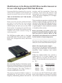
Modifications to the Motorola UHF Micor mobile transceiver
for use with high speed FSK Data Modems
It is assumed that those attempting this conversion receiver and the transmitter. Since one
will have the test equipment, service manuals, and oscillator serves both the receiver and
expertise necessary to tune and service this radio. transmitter, the transmit frequency will
“track” the receive frequency as it changes
THIS IS DEFINITELY NOT THE RADIO with temperature.
FOR BEGINNERS.
The transmitter incorporates a circulator in the
Please review the conversion instructions before antenna output network to protect the PA
you begin. In several areas, there are two sets of transistors from high SWR. The presence of a
instructions, one set is for use with a TAPR/ circulator insures that the UHF Micor will be
G3RUH modem, the other is for use with a TPRS a “good neighbor” when installed at a site that
Texnet modem. You might want to mark the steps is shared by other services.
that apply to your modem. This could prevent some
confusion and possible mistakes during the Before proceeding any further, take a few
conversion process.
minutes to become familiar with the radio
that you plan to convert. Refer to the
The UHF Micor mobile radio is a fine high illustrations in the Motorola Service Manual
power UHF radio. This unit is a true “cadillac” for the location of major components.
radio that incorporates many advanced _______________________________________________________
features.
Now that you know the physical layout of the
radio, let’s cover some of the technical aspects.
What is the transmit power output ?
The answer to this question can be found by
looking at the model number. The chart below
translates these numbers into useful
information.
While the model number may contain a
combination of 11 or more numbers and
letters, the first 5 of these are the ones of
interest. The rest describe various options such
as “ PL “.
The transmitter employs a hetrodyne exciter.
Receiver oscillator injection is mixed with the
signal from an offset oscillator to generate the
transmit frequency. The offset oscillator is
varactor modulated for true FM.
Model
T34RTA
T44RTA
T54RTA
T74RTA
25W
45W
75W
100W
Transmit current
10.5 A @ 13.6 V
15.9 A @ 13.6 V
25.0 A @ 13.4 V
35.5 A @ 13.4 V
The receive channel element output is As you can see, the 75 and 100 watt radios
multiplied by 24 and serves as the main draw a lot of current on transmit. If you have
frequency determining element for both the one of these radios and you don’t need that
3
much RF or your power supply can’t handle
the load, don’t worry. There is a power adjust
control that will allow you to lower the power.
For the record, I would not recommend
reducing the TX power more than 50 % with
this control. Any greater reduction might lead
to instability in the PA stages.
Simplex and wide-spaced exciters require no
crystal or component changes. The only
change necessary is conversion from voice to
FSK data modulation.
If your crystal is marked 14700, STOP! You
have a 470-512 MHz radio and conversion
isn’t practical if not impossible.
________________________________________________________________________
Before ordering crystals and conversion parts
you must determine the exciter configuration
for your radio. The following information
covers the most common configurations.
This would be a good time to check the parts
list in Appendix C and order the crystals and
conversion parts.
A standard exciter UHF Micor transmits ________________________________________________________________________
5 MHz higher than it receives.
The major problem in conversion happens
A wide-spaced exciter has 2 offset when you decide to add a preamp to the
oscillators. One provides +5 MHz receiver. Some preamps will not work with
transmit. The other is for simplex this radio. The antenna network is picky about
operation or talk-around as it’s known in the load impedance presented to the receiver
the commercial two-way field.
port. The WA5VJB preamps commonly used
with the RCA 700’s act like an attenuator when
The 11.7 MHz exciter is configured for used in a Micor. Several preamps that will
simplex operation.
work are the Ramsey PR-40, and the original
equipment Motorola TLE-8192A. Physical size
The most common exciter is the standard and price make the PR-40 the best choice.
+5 MHz version. With one exception, you will Unless you can find a TLE-8192A on the
need to remove the exciter board in order to surplus market, skip this one. Current price
determine which version is installed in your on a new 8192A is $171.00.
radio. The one exception is the wide-spaced
exciter. Before removing the exciter board, Important note: If possible, check the radio
check for the presence of a second exciter at its original operating frequency before you
output network L402-L407. If you have this proceed with conversion.
network, you have a wide-spaced exciter.
_______________________________________________________________________
If you don’t have the network, proceed with With the basics covered, it’s time to begin
removal of the exciter board. Locate the offset conversion.
oscillator crystal. It should be the only crystal ________________________________________________________________
on the board. If it’s marked 16700, then you
have a standard exciter. This version requires
that you change the 16.7 MHz crystal to 11.7
and make several component changes. If you
have an 11700 crystal, you have a simplex
exciter.
4
3. Remove the audio-squelch board. This
board is held in place by 4 screws and is
removed from the top side of the radio.
PL Encoder and decoder removal.
If you do not have an encoder or decoder, skip to
step 3. If you have one board but not the other,
follow step 1 or 2 and then skip to 3.
1. Remove RX PL decoder board (if
installed). This board plugs in to the
audio-squelch board from the bottom side
of the radio. The decoder location is
shown in the bottom view of the radio.
Refer to the audio squelch board layout
for the location of JU201. If JU201 is not
installed, add this jumper using a short
length of insulated wire. This finishes
work with the audio squelch board. When
you place this board back in the radio, be
sure that the 6 pins that plug into the audio
power amplifier board (2 transistors on a
heatsink mounted to the side of the radio)
mate correctly.
2. Remove the TX PL encoder (if installed).
This board plugs into the excter board
from the bottom side of the radio. The
encoder board location is also shown in
the bottom view of the radio.
5
4. Remove the exciter board. This board is Receiver modifications.
held in place by 7 screws. You will also 1. Diasble RX AFC. There is an alignment
need to remove 2 (or 3 WS) phono plug
access hole at the left rear of the RX shield
connections. One is the exciter output
cover with the label “AFC OFF”. Insert a
connection to L302-307 (also a connector
felt tip marker into the hole and mark the
to L402-L407 WS), the other is the injection
circut pad on the receiver board that
from the receiver to the exciter. This
corresponds to this test point. Remove the
connection is made on the component side
shield cover and install a jumper wire
of the board.
from this pad to ground. For those
working from schematics, this is the same
as soldering a jumper across C115.
5. Refer to the exciter layout showing the
location of P401. Add a jumper (if one is
not present) between P401-2 and P401-4.
Note that the circut traces that connect to
pins 2 and 4 extend to pads on the left side
of P401. Install an insulated jumper at this
location.
2. Select the F1 channel element position.
Solder a jumper wire between pins 1 and
2 of P904. P904 is the group of connector
pins that connect the receiver RF IF board
to the control interconnect board. P904 is
divided into 2 parts. Pins 1-9 are toward
the rear of the radio and pins 10-16 are
near the front.
6
If you are using a TAPR/G3RUH Modem, skip If you are using a TAPR/G3RUH modem,
follow steps 5a and 6a. If you are using a
steps 3 ,4, 10 and 11.
TPRS modem, follow steps 5b and 6b.
3. Refer to Appendix A for the data inverter
schematic. Build the data inverter on a 5a.Cut the leads of a 10K and a 15K 1/4 w
resistor to 1/4 “. Solder one lead of the
small piece of perfboard. You may choose
10K resistor to pin 15 of J904. J904 is the
to install the volume and squelch pots on
connector on the control interconnect
this same piece of board. The volume and
squelch pots are optional. They are not
board that mates with P904 on the receiver
RF-IF board. Excercise caution when
needed for data. You can omit them unless
soldering the resistor lead. Do not
you want to use a speaker to monitor channel
inadvertently solder the connector pin on
activity.
the RF-IF board to the receptacle pin on
the interconnect board. Solder a 15K
Before you decide to skip installation of the
resistor from the “free” lead of the 10K
volume and squelch pots, be advised that
you will need to make temporary
resistor to ground.
provisions for these controls during
5b.Cut the leads of a 150K 1/4 w resistor to
receiver alignment
1/4”. Solder one lead of this resistor to pin
15 of J904. J904 is the connector on the
4. After you have completed the data
control interconnect board that mates with
inverter, use small “L” brackets to mount
P904 on the receiver RF-IF board.
the board to the shield that separates the
Excercise caution when soldering the
control interconnect board and the
resistor lead. Do not inadvertently solder
receiver circuts. The preferred mounting
the connector pin on the RF-IF board to
position is on the receiver side of the shield
the receptacle pin on the interconnect
and located over audio squelch board.
board.
6a.Prepare a 7 “ length of RG-174 or similar
shielded cable. Connect the center
conductor to the junction of the 10K and
15K resistors. Solder the shield to the
ground foil on the interconnect board.
Picture of Perf Board for TPRS Modem modification.
Mounted in Upper Right Corner.
Picture of Perf Board for TAPR/G3RUH Modem
modification. Mounted in Upper Right Corner.
7
Pin 16 of P904 is connected to ground and
the foil that connects to this pin is a good
place for the shield connection. It may be
necessary to use a screwdriver or Xacto
knife to remove some of the protective
coating that covers the ground foil. The
free end of this coax will be connected to
the power plug in step1a under the
headiing Data Connections.
Pin 3.
The emitter follower output
(also known as audio/squelch high).
Pin 5.
Volume arm.
Pin 6.
Chassis ground.
Pin 9.
Squelch.
Refer to the audio/squelch control
schematic in Appendix A. If you did not
mount the controls and their associated
resistors on the data inverter board, devise
your own mounting for these
components.
6b.Prepare a 10 “ length of RG-174 or similar
shielded cable. Connect the center
conductor to the free end of the 150K
resistor. Solder the shield to the ground
foil on the interconnect board. Pin 16 of
P904 is connected to ground and the foil
that connects to this pin is a good place
for the shield connection. It may be
necessary to use a screwdriver or Xacto
knife to remove some of the protective
coating that covers the ground foil. The
free end of this coax will be connected to
the data inverter board.
Connect the wires from J903 to the
appropriate points.
10.Power for the data inverter can be
obtained at the Extra Filtered A+ point on
the control inteconnect board. The chassis
ground connection can be made on the
ground foil adjacent to pin 16 of J904.
11. Connect the shielded cable from the
discriminator to the input of the data
inverter.
Refer to the Control Interconnect board
illustration for the following steps.
12.If you plan to install a receive preamp, do
so at this time. The power connection
should be made at the Extra Filtered A+
point.
7. Solder an insulated jumper wire across
pins 5 and 6 of K902. This connection can
be made of the top side of the circut board.
8. Solder a 1N4001 or similar diode across
pins 1 and 2 of K901. The banded end
should connect to pin 1.
Control Interconnect board
illustration
9. If you wish to mount the volume and squelch
controls in the radio perform the following
steps.
Solder wires to the following pins on the
J903. J903 mates with pins on P903 on the
audio/squelch board. When soldering to
the pins of J903, use caution to keep from
soldering the pins on the audio/squelch
board to the mating pins on J903. As a
precaution you may choose to remove the
audio/squelch board.
8
1a.RX Data Out. Connect the shielded cable
from the 10K resistor at the RX
discriminator output to P901-27 center,
P901-28 shield.
Data Connections.
Data connections to the outside world are
brought out on unused pins on the power plug
P901. These connections are as follows:
Pin
27
28
29
30
31
32
1b.RX Data Out. Connect a shielded cable
from P901-27 center, P901-28 shield, to the
RX data inverter output.
Function
RX Data
RXD shield
PTT
PTT shield
TX Data
TXD shield
2. PTT. Connect a 12 “ length of shielded
cable to P901-29 center, P901-30 shield.
The other end of this cable will be
connected in the PTT configuration
instructions.
On some radios (12 frequency) there may be
wires connected to these pins. Remove these
wires as they are not needed. Follow the wires
back to the 12 frequency adapter on the
receiver RF board and cut them loose at this
point.
3. TX Data In. Connect a shielded cable to
P901 -31 center, P901-32 shield.
4. Build the TX audio buffer/amplifier stage
on a small piece of perfboard. Follow the
schematic in appendix B. After you have
completed the amplifier, use small “L”
brackets to mount the board to the shield
that separates the control interconnect
board board and the receiver circuts. The
preferred mounting position is on the
receiver side of the shield and located over
the audio /squelch board.
If you are using a TAPR/G3RUH modem,
follow steps 1a, 2 and 3-7. Don’t take a short
cut by skipping construction of the buffer
amplifier (see appendix ?? shcematic). This
stage is necessary for proper modem to radio
interface. Without it, the radio will exhibit
poor frequency stability and the modulation
symmetry will be miserable (you may have a
deviation of positive 3.5 khz and a negative
2.0 kHz). Follow the exciter modifications .
DO NOT TRY TO USE ANY OF THE
EXISTING AUDIO CIRCUTS IN THE
TRANSMITTER.
5. Power for the buffer amplifier can be
obtained at the Extra Filtered A+ point on
the control inteconnect board. The chassis
ground connection can be made on the
ground foil adjacent to pin 16 of J904.
If your are using a TPRS modem, follow steps
1b, 2 and 8.
6. Connect the shielded cable from P901-31,
32 to the input of the buffer amplifier.
7. Run a piece of shielded cable from the
output of the buffer amplifier to the
exciter. Route this cable through the hole
in the side of the exciter shield
compartment. This is the same hole that
the receiver oscillator injection cable runs
through. Leave 6 to 8 inches of extra cable
in the exciter compartment so that the
exciter board can be removed with the
data cable connected.
Picture of Perf Board for TAPR/G3RUH Buffer Amplifier.
Schematic in Appendix ??
9
8. TX Data In. (TPRS Modem) Connect a
shielded cable to P901-31 center, P901- 32
shield. Route this cable from the power
plug to a hole in the side of the exciter
shield compartment. This is the same hole
that the receiver oscillator injection cable
runs through. Leave 6 to 8 inches of extra
cable in the exciter compartment so that
the exciter board can be removed with the
data cable connected.
If you have a 11.7 MHz exciter, follow the +5 MHz
conversion and skip all of the component changes
in step 6.
+5 MHz Exciter Modifications
Refer to the standard exciter illustration when
performing the following steps.
1. Remove the exciter board from the radio.
2. Remove C316 (.001). Install a jumper wire
in place of C316.
PTT Configuration.
The PTT can be configured in two ways.The
first is an active low PTT which is standard
on the Micor. The second is an active high PTT.
The RCA 700 radios used this polarity. I prefer
the active high PTT to maintain compatability
with modems configured for the RCA 700.
Select the one that is most appropriate for your
application.
If you are using a TAPR/G3RUH modem,
follow the instructions for active low PTT.
If the active low PTT output is selected on the
TPRS modem, connect the PTT cable from the
power plug to the following pins on J910 (the
metering control socket on the control
interconnect board. Center conductor to pin 5
(PTT) and the shield to pin 6 (Chassis
Ground).
If the active high PTT output is selected, build
the 2N2222 PTT inverter stage as shown in
Appendix A. The PTT cable from the power
plug should be connected to the input of this
stage and the ouput should connect to pins 5
(PTT) and 6 (Chassis Ground) of J910.
Exciter Modifications
Two sets of instructions are provided for the
exciter modifications. The first set is for the
standard +5 MHz exciter. The other set is for
those with a wide-spaced exciter.
10
3. Unsolder the lead of R319 (15K) that IS
NOT connected to the same circut pad
as the cathode of varicap diode CR301.
Leave this end of R319 free. It will be
used later.
4. Install a 100k resistor across the varicap
CR301.
5. Locate the trace that runs from the anode
of CR301 to the audio section on the
other end of the exciter board. This trace
is on the component side of the board.
Cut this trace adjacent to the connection
at CR301
6. Change the following components on the
exciter board.
Part #
C332
C333
C334
L300
L310
L311
L312
L313
R321
Y301
Old
36 pf
75 pf
68 pf
Blue
1.1 uH
4.6 uH
2.3 uH
.57 uH
15 K
16.7 MHz
New
Motorola Part #
51 pf
21-82610C07
110 pf
21-82610C69
100 pf
21-82610C44
Red
24-83879G10
1.7 uH
24-82835G12
6.7 uH
24-82835G29
3.5 uH
24-82835G11
.82 uH
24-82835G13
5.6 K
None
11 7 MHz ICM Prt # 167561
7. Connect the shield of the TX data cable to
the jumper installed in place of C316.
8. Connect the center conductor of the TX
data cable to the free end of R319 (15K).
This completes the standard exciter
modifications. Re-install the exciter in the
radio. Be sure to re-connect the reciver
oscillator injection and exciter output
cables.
Radio Alignment
The location of the various alignment points
should be clearly marked on the shield covers
of the receiver, exciter, and power control
boards. Use a VOM on the 50 uA scale when
meteing the various test points. The various
meteing points can be determined by the
following method.
This completes the standard exciter
modifications. Re-install the exciter in the Look at the meter plugs from the top of the
radio. Be sure to re-connect the reciver radio. The plug consists of seven pins in two
oscillator injection and exciter output cables. rows. The top row has four pins. The bottom
row has three. The top row is read from left to
Wide-spaced Exciter Modifications
right and the bottom row from right to left.
Refer to the wide-spaced exciter illustration One lead of the VOM will connect to the
when performing the following steps.
appropriate metering point and the other lead
will connect to ground.
1. Remove the exciter board from the radio.
1 2 3 4
2. Remove C317 (.001). Install a jumper wire
7 6 5
in place of C317.
As you tune the various stages, it may be
3. Unsolder the lead of R403 (15K) that IS necessary to swap the polarity of the meter
NOT connected to the same circut trace leads in order to obtain an upscale reading on
as the cathode of varicap diode CR401. the VOM.
Leave this end of R403 free. It will be used
later.
Receiver Alignment
4. Install a 100K resistor across the varicap 1. Adjust L101 through L105 to the end of
CR401.
the coil form away from the circut board.
5. Cut the circut board trace that connects
one end of R320 to the anode end of
CR401.
6. Connect the shield of the TX data cable to
the jumper installed in place of C317.
7. Connect the center conductor or the TX
data cable to the free end of R403 (15K).
This completes the wide-spaced exciter
modifications. Re-install the exciter in the
radio. Be sure to re-connect the receiver
oscillator injection and exciter output cables.
11
2. Adjust tuning screws of L106 through
L108 until each screw extends about 1/8
“below the receiver shield. Preset tuning
screws of L111 through L116 so that the
screw end is in the space between the
board and its shield, and about 1/8 “ from
the shield.
3. Meter position 1. Alternately tune L101
and L102 CCW two turns at a time for a
peak on Meter 1.
4. Meter position 2. Tune L103 CCW for a
peak on M2. Tune L104 CCW for a dip on
M2.
5. Meter position 3. Tune L105 CCW for a peak
on M3. Tune L104 for a peak on M3. Re-peak
both coils.
Tune L111 through L116 for best noise
quieting. Repeat until no further
improvement can be made.
6. Meter position 3. Detune L101 until meter 3
drops to 10 uA. Tune L103 for peak M3
reading. Keep this peak below 12 uA by
further detuning of L101 if necessary.
15. If you have installed a preamp, follow the
instructions supplied with the preamp and
tune for minimum reading on the AC
voltmeter. Sensitivity with a preamp will be
approximately .25 uV for 20 dB of quieting
or .175 uV for 12 dB SINAD.
7. Meter position 1. Alternately tune L101 and
L102 for peak M1 reading.
Exciter Alignment
8. Meter position 3. Tune L106 for a dip on M3. Note: Adjustments that pertain to wide-spaced
Tune L107 for a peak on M3. Tune L108 for exciters are enclosed in brackets. If you are
a dip on M3. Do not repeat.
converting a wide-spaced radio, skip the
adjustments that are not enclosed in brackets.
9. Meter positions 4,5. Discriminator- Inject an
11.7 MHz signal into L110 hole on the 1. Adjust the slug in L301 [L401] so that the
receiver shield. Insert the injection probe
end is flush with the circut board. Adjust
wire far enough into L110 to obtain a
the tuning screws in L302 to L307 [L402 to
saturated reading on M5. Tune L109 for an
L407] fully CCW until each screw is fully
exact zero reading on M4. This adjustment
extended. There is a stop on each screw
is critical.
which will keep it from being completely
removed from the filter.
10. Unsquelch the receiver. Connect a signal
generator to the antenna connector and set 2. Meter position 4. Disable offset oscillator.
the RF output of the generator to maximum.
Short TP301 to ground. M4 should read zero
when this point is shorted to ground.
11. Using a frequency counter, count the RX
injection frequency at the injection output 3. Connect a wattmeter terminated with a 50
to the exciter. The correct reading will be 11.7
ohm dummy load to the antenna connector.
MHz below the operating frequency. Adjust
the channel element warp capacitor until the 4. Meter position 2 [3]. Remove the exciter
correct reading is obtained.
input cable from the receiver RF deck.
Connect this cable to a signal generator
12. Meter position 4. Adjust the signal generator
using the appropriate adapters. Set the
frequency for an exact zero reading on M4.
signal generator to the desired transmit
frequency and set the output level to 50-70
13. Meter postion 5. Tune L111 through L116 for
millivolts. Key TX and adjust L301 CW
peak reading on M5. Reduce signal
[L401] for a peak reading on M2 [M3]. Adjust
generator output to keep M5 out of
the generator output for a M2 [M3] reading
saturation. Tune L110 for peak on M5.
at the center of the meter scale.
Repeat adjustment of L111 through L116.
5. Meter position 2 [3]. With TX keyed, adjust
14. Connect a AC voltmeter across the speaker
L302 [L402] for minimum M2 [M3] reading.
leads. Tune L106 through L108 for best noise
Adjust L303 [L403] for a peak reading.
quieting (minimum meter reading).
Adjust L304 [L404] for a minimum reading.
12
Adjust L305 [L405] for a peak reading.
Adjust L306 [L406] for a minimum reading.
Adjust L307 [L407] for a peak reading.
Adjust L302 through L307 [L402 through
L407] CW (in) one-half turn each.
14. Connect the radio to the TPRS 9600 baud
modem. Remove output jumper S1 on the
modem.
15. Key the transmitter with the modem PTT
and adjust L300 [L400] to set the
transmit frequency.
6. At this point unkey the transmitter.
Continue to supply an on frequency signal
to the exciter with the signal generator. Key
the transmitter. You should see an indication
on the wattmeter. Using the power adjust
control, set the output power to the correct
level for your radio. If you wish to reduce
the output power, DO NOT turn the level
to less than 20 watts. There is protection
circut that will disable the PA stages if the
output power drops too low.
16. Install jumper S1 in the modem. Key the
transmitter with the modem PTT and s e t
the deviation to 3.0 kHz.
17. Remove jumper S1 and check the transmit
frequency. If necessary, adjust L300 [L400]
to bring the radio back on frequency.
18. Install jumper S1 and verify that the
deviation is still in the area of 3 kHz. The
frequency and deviation adjustments tend
to interact. If necessary, repeat steps 17 and
18. DO NOT adjust the transmit frequency
without removing jumper S1 in the
modem.
7. Remove the short at TP301. Set the slug in
coil L300 [L400] to the center of its range.
8. Disconnect the signal generator and reconnect the exicter input cable to the receiver
RF deck.
9. Key the transmitter. You should see RF
output. If necessary, use the power adjust
control to reset the power to the desired
level. If you are using a TPRS modem, the
frequency may be 10 or so kHz off until you
connect the 9600 baud modem.
The presence of TX data on the modulator will
give a false reading.
Modem Interface Notes
TAPR 9600 baud Modem Modifications
Install a 1 uf monolythic capacitor across C8 in
older units, C7 in later versions, a .1 uf
If you are using a TAPR/G3RUH modem, follow monolythic in the RX input circut.
steps 10 thru 13 to set transmitter frequency and
deviation. If you are using a TPRS modem,
follow steps 14 thru 18.
TPRS 9600 Baud Modem modifications:
1. Remove R28, a 220K resistor.
10. Connect the radio to the 9600 baud modem. 2. Solder a jumper wire across R29, a 330K
resistor.
11. Key the transmitter and adjust L300 [L400]
to set the transmit frequency.
Both of these resistors are in the RX Data
input circut that feeds pin 3 of IC U10 i n
12. Using the transmit level pot in the modem,
the modem. For more information, refer to
the modem schematic.
set the deviation to 3 kHz.
13. Re-check transmit frequency setting.
13
14