1
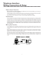
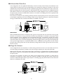
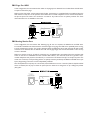
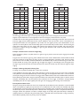
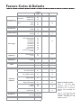
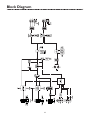
Universal Telephone Interface
UTI1 Model
Addendum to the Installation and Use Manual
The following corrections to the UTI1 manual, part number 54-2095-01A, are highlighted in bold and underlined.
Trunk Disconnect (page 7)
The trunk disconnect feature is disabled by default and can be enabled. (Refer to System Programming.)
Override Input (page 10)
Maximum contact closure resistance is 1000 ohms. Open collector type outputs for controlling a page may also be used.
The Override feature includes a quad beep pre-announce tone that can be enabled or disabled. (The default is enabled.)
NOTE: SYS GND has been added
to the line drawing on page 10
next to Dry Audio Input.
Override Tone (page 13)
This tone is produced when override is activated. It produces a quad beep pre-announce tone that can be enabled or
disabled. (The default is enabled). See System Programming to disable the tone.
Feature Codes & Defaults
Feature
Code
Feature
Override Tone
Disable
Enable
08
09
Trunk Disconnect
Disable
Enable
14
15
Data
Default
09
14
Block Diagram
NOTE: SYS GND has been
added to the block diagram
next to Dry Audio Input.
© 2004 Bogen Communications, Inc.
All rights reserved.
Specifications subject to change without notice.
54-6707-01A 0408
50 Spring Street, Ramsey, NJ 07446, U.S.A.
Tel. 201-934-8500, Fax: 201-934-9832, www.bogen.com
Universal Telephone Interface
UTI1 Model
Installation and Use Manual
© 2004 Bogen Communications, Inc.
All rights reserved.
Specifications subject to change without notice.
54-2095-01A 0406
© 2004 Bogen Communications, Inc.
Important Safety Information
All Rights Reserved. Printed in Taiwan.
Always follow these basic safety precautions when installing and using
the system:
Notice
Every effort was made to ensure that the information in this manual
was complete and accurate at the time of printing. However,
information is subject to change.
FCC Statement (Part 15) - Radio Frequency Interference
The Universal Telephone Interface (UTI1) generates and uses radio
frequency energy and if not installed and used in strict accordance
with the manufacturer's instructions, may cause interference to radio
and television reception. Testing is being conducted for compliance
with the limits for a Class B device in accordance with the
specifications in Part 15 of the FCC Rules and Canadian D.O.C.
regulations. This testing is designed to provide reasonable protection
against such interference. However, there is no guarantee that
interference will not occur in a particular installation. If this equipment
does cause interference to radio or television reception, which can be
determined by turning the UTI1 unit off and on, the user is
encouraged to try to correct the interference by one or more of the
following measures:
- Reorient the radio or TV receiving antenna.
- Relocate the UTI1 unit with respect to the radio or TV receiver or
vice versa.
- Plug the UTI1 unit into a different outlet so that it and the radio or
TV receiver are on different branch circuits.
If necessary, the user should consult the dealer or an experienced
radio/television technician for additional suggestions.The user may find
the following booklet, "How To Identify and Resolve Radio-TV
Interference Problems," helpful. This booklet was prepared by the
Federal Communications Commission (FCC) and is available from the
U.S. Government Printing Office,Washington, DC 20402. Stock order
No. 004-000-00345-4.
Federal Communications Commission (FCC) Statement
(Part 68)
This equipment is component registered with the Federal
Communications Commission (FCC) in accordance with Part 68 of its
rules. In compliance with the rules, be advised of the following:
Registered equipment may not be used with Coin Telephone Lines.
Equipment may be used with Party Lines in areas where state tariffs
permit such connections and when equipment is adaptable for such
service.
This equipment is registered as follows:
Registration Number - CD2PA14BUT11
Ringer Equivalence - 1.4B
If trouble is experienced, the equipment should be disconnected from
the interface to determine if this equipment, or the telephone line, is
the trouble source. If the equipment is determined to be
malfunctioning, it should not be reconnected until repairs are effected.
Repairs to this equipment, other than routine repairs, can be made
only by the manufacturer or its authorized agents.
If the equipment causes harm to the telephone network, the local
telephone company may temporarily discontinue your service and, if
possible, notify you in advance. If advance notice is not practical, you
will be notified as soon as possible.You will be given the opportunity
to correct the problem and informed of your right to file a complaint
with the FCC.
The local telephone company may make changes in its facilities,
operations, or procedures that could affect the proper functioning of
your equipment. If they do, you will be given adequate notice in writing
to allow you an opportunity to maintain uninterrupted telephone
service.
1. Read and understand all instructions.
2. Follow all warnings and instructions marked on the product.
3. DO NOT block or cover the ventilation slots and openings. They
prevent the product from overheating. DO NOT place the product
in a separate enclosure or cabinet, unless proper ventilation is
provided.
4. Never spill liquid on the product or drop objects into the
ventilation slots and openings. Doing so may result in serious
damage to the components.
5. Repair or service must be performed by a factory authorized
repair facility.
6. The product is provided with a UL-CSA approved, 3-wire ground
type plug. This is a safety feature. DO NOT defeat the safety
purpose of the grounding type plug. DO NOT staple or otherwise
attach the AC power supply cord to building surfaces.
7. DO NOT use the product near water or in a wet or damp place
(such as a wet basement).
8. DO NOT use extension cords. The product must be installed
within 6 feet of a grounded outlet receptacle.
9. DO NOT install telephone wiring during a lightning storm.
10. DO NOT install telephone jacks in a wet location unless the jack
is specifically designed for wet locations.
11. Never touch uninsulated wires or terminals, unless the line has
been disconnected at the paging or controller interface.
12. Use caution when installing or modifying paging or control lines.
Contents
UTI1 Feature Callouts ..........................................................................................................4
Introduction ............................................................................................................................5
Voice Channel ................................................................................................................................................5
Background Music ..........................................................................................................................................5
Signaling Tones ................................................................................................................................................5
Other Features ..............................................................................................................................................5
Package Contents ..........................................................................................................................................5
Installation ..............................................................................................................................6
Wall Mounting ................................................................................................................................................6
Telephone Interface Wiring Connections & Setup ............................................................7-10
Telephone System Connections..................................................................................................................7
Trunk Disconnect ..........................................................................................................................................7
PBX Loop Start Trunk Port ........................................................................................................................7
PBX Ground Start Trunk Port ....................................................................................................................8
PBX Page Port Contact ................................................................................................................................8
PBX Page Port VOX ......................................................................................................................................9
PBX Analog Station Port ..............................................................................................................................9
Override Input ................................................................................................................................................10
Other Connections ................................................................................................................11
Night Ringer ....................................................................................................................................................11
Tone Trigger ....................................................................................................................................................11
Paging Output Connections ........................................................................................................................11
Background Music Input ..............................................................................................................................11
Aux Contacts ..................................................................................................................................................11
Controls ..................................................................................................................................12
Paging Level......................................................................................................................................................12
Music Level ......................................................................................................................................................12
Music Mute Level............................................................................................................................................12
Tone Level ........................................................................................................................................................12
Limiter Threshold ..........................................................................................................................................12
Tones........................................................................................................................................13
Pre-Announce/Confirmation Tone ............................................................................................................13
Tone Trigger ....................................................................................................................................................13
Override Tone ................................................................................................................................................13
Setup Tone........................................................................................................................................................13
Reference ................................................................................................................................13
How to Page....................................................................................................................................................13
Priority Levels ................................................................................................................................................13
System Programming............................................................................................................14-15
Default Timer ..................................................................................................................................................14
VOX Timer ......................................................................................................................................................14
DTMF Block ....................................................................................................................................................14
Setup Tone........................................................................................................................................................14
Reset Default Values ......................................................................................................................................14
AUX Relay Contact ......................................................................................................................................15
Feature Codes and Defaults..................................................................................................17
Specifications ..........................................................................................................................18
Block Diagram........................................................................................................................19
Limited Warranty ..................................................................................................................20
3
UTI1 Feature Callouts
1. Power Indicator - Illuminates when AC power has been applied to the unit.
2. AUX Contact Terminals - Provide connections for normally open and normally closed contact closures.The
contact closure can be programmed to activate during paging, night ring, tone, override, or any combination (refer to
System Programming).
3. Ground Start Terminal - Connection for PBX ground. Used only when the ground start interface is selected.
4. Tone Terminals / Tone Level Control - Terminals provide connections to night ring and tone trigger inputs.Tone
Level Control sets the level of all tones produced by the system.
5. Override - Secondary paging input with higher priority than TRUNK/PAGE PORT or STATION mode inputs.
Connects to either loop start trunk or dry audio signal with contact closure.
6. Trunk/Page Port - Primary paging interface to telephone system when UTI1 is set to trunk or page port mode type
interface.
7. Interface Type Slide Switches - Sets telephone interface type for the UTI1.
8. Station Port - Primary paging interface to telephone switch when UTI1 is set to station mode type interface.
9. Limiter Threshold / Limiter Active LED - Control and indicator for output limiter function.
10. Music Input Jacks - Stereo summing input for background music source.
11. Page & Music Terminals - Provides connections to the paging system (background music and voice paging) and the
24V DC power supply.
12. Page Only Terminals - Provides connections to the paging system (voice page only - no music) and the 24V DC
power supply.
13. Program/Run Switch & LED - Used to switch unit to program mode.The LED will light when unit is in
PROGRAM mode.
14. Music Level Control - Music Level sets background music level.
15. Music Mute Control - Music Mute sets music mute level during paging.
16. Page & Music Level Control - Page & Music Level controls the level of page & music output.
17. Page Only Level Control - Page Only Level controls the level of page only output.
4
Introduction
The UTI1 Paging System is a paging and signaling system.The system provides the following features and functions:
Voice Channel
• Single-zone paging
• Telephone interfaces:
-
loop start trunk
ground start trunk
station access (analog ring-up)
page port contact closure activation
page port voice activation
• Override paging (using loop start trunk or page port contact closure activation)
• Two audio outputs (both with level controls):
- paging and background music
- paging only
• Each output can provide audio for 150 Bogen one-way amplified speakers, also compatible with 70V amp inputs
• Pre-Announce/Confirmation Tone
• Adjustable Automatic Level Control with threshold and active indicator
Background Music
• High impedance transformer isolated BGM input with volume control
• Variable music mute
Signaling Tones
• Night Ringer (contact closure activation)
• Tone Trigger (tone and duration selectable, closure-activated)
Other Features
•
•
•
•
•
•
C-form contact set with programmable activation events
Non-volatile memory for setup data (no backup battery required)
Setup Tone to assist in volume setting, etc.
Pluggable terminal strips
Microcontroller-based operation
DTMF setting of operating parameters
Package Contents
• (1) UTI1
• (1) Installation and Use Manual
5
Installation
Wall Mounting
Mounting to a plywood backboard or studs:
1.
2.
3.
4.
Hold the unit level against the surface to which it will be mounted.
Mark where the mounting screws should be positioned.
Set the unit aside and install the screws leaving about 1/4" of the screws sticking out of the surface.
Slip the unit over the screws and tighten them snugly.
6
Telephone Interface
Wiring Connections & Setup
Telephone System Connections
The UTI1 connects to virtually any telephone system: PBX station lines and CO lines, PBX loop start trunk ports,
PBX ground start trunk ports, and page ports.
Interface installation consists of setting the slide switches and connecting with modular (RJ11) telephone plugs. Refer
to the appropriate procedure in this section to connect the UTI1 to the telephone system.
Note: In all cases, make sure that power to the UTI1 is disconnected before performing the installation.
Trunk Disconnect
The UTI1 includes a trunk disconnect feature.The purpose of the trunk disconnect feature is to release the UTI1
from the trunk port in the event a user does not hang up the phone properly after making a page. If the UTI1 does
not detect voice for the interface VOX time-out period, or if the interface default timer expires, the UTI1 will
attempt to release from the trunk. When using the trunk disconnect feature with a trunk interface, the PBX must
have disconnect supervision available on the trunk port connected to the UTI1. The trunk disconnect feature is
enabled by default and can be disabled. (Refer to System Programming.) To set the VOX and default timers refer to
System Programming.
PBX Loop Start Trunk Port
In this configuration, the unit supplies a 24V talk battery and loop current detection.When the unit detects a loop
resistance between Tip and Ring, it activates.When the loop opens, the page ends.The unit follows the status of the
trunk port.
Before configuring the UTI1 for a loop start trunk port, make sure that the power is disconnected and all other
connections are completed. Move the slide switches on the UTI1 to the positions shown below. Use a modular
telephone cord to connect the module to the phone system.
The center two conductors are Tip and Ring (24V DC) and have a specific polarity as shown in the figure to the
right. If the polarity that the trunk requires is opposite, you can use a reversing modular cord to make the
connection or reverse the connection through a modular block. The trunk disconnect feature is available in this
mode.
7
PBX Ground Start Trunk Port
In this configuration, the unit supplies 24V talk battery, a contact in the Tip circuit, and loop current detector in the
ring line. When the ground start trunk grounds Ring, the unit responds by closing the connection to Tip, which
completes the access procedure.When the loop is opened, the page ends.The unit follows the status of the trunk.
Before proceeding, make sure that the power is disconnected and all other connections are completed. Move the
slide switches on the UTI1 to the positions shown below. Use a modular telephone cord to connect the module to
the phone system. Connect the GND STRT terminal on the module to the PBX ground. This is typically the AC
ground for the PBX system.
The center two conductors are Tip and Ring (24V DC) and have a specific polarity as shown. If the polarity that the
trunk requires is opposite, you can use a reversing modular cord to make the connection or reverse the connection
through a modular block.The trunk disconnect feature is available in this mode.
IMPORTANT:
When the GND STRT terminal is connected to earth ground, it is important that none of the UTI1 system ground
terminals are connected to earth ground. These terminals may accidentally be connected to earth ground when
external equipment, such as a CD player, tuner, announcement device, etc., is connected to the UTI1. The closure
return terminals for the Trunk/Page Port jack, the contact closure (GND), the left-most Dry Audio input terminal
of the Override jack, the C terminal of the Night Ring, and the Tone Trigger input are system ground.The background
music input and page outputs are transformer-isolated and are unaffected by earth ground. If the UTI1 system
ground is tied to earth ground, then the UTI1 talk battery voltage will be shorted to ground and the unit will not
function properly.
PBX Page Port Contact
In this configuration, the unit responds to a contact shorting the closure source to its return. When the short is
removed, the page ends. Audio is provided to the system through a separate pair of dry audio input leads.
Make sure that the power is disconnected and all other connections are completed before proceeding. Move the
slide switches on the UTI1 to the positions shown below. Use a modular telephone cord to connect the module to
the phone system.
The center two conductors are used for dry audio (no DC voltage) and the connectors on either side are
connected to the page port contact closure. The maximum resistance of the page port contact closure loop
resistance is 1000 ohms. Open collector type outputs for controlling a page may also be used.The trunk disconnect
feature is not available in this mode.
8
PBX Page Port VOX
In this configuration, the unit activates when audio on the page input is detected. Loss of audio allows the VOX timer
to expire and ends the page.
Make sure that the power is disconnected and all other connections are completed before proceeding. Move the
slide switches on the UTI1 to the positions shown below. Use a modular telephone cord to connect the module to
the phone system. The center two conductors are used for dry audio and are not polarity sensitive. The Trunk
disconnect feature is not available in this mode.
PBX Analog Station Port
In this configuration, the unit answers after detecting ring. As soon as it answers, the default timer and VOX timer
are started.The default timer determines the maximum length of any page.The VOX timer repeatedly resets as long
as audio is detected on the line. If no audio is detected within the VOX time period, then the page will end. If audio
continues to be detected, then the default timer will control page length. The unit will disconnect if a loss of loop
current is detected.
Make sure that the power is off and all connections are completed before proceeding. Move the interface slide
switch on the UTI1 to STATION. The other interface slide switch is not used and can be in any position. Use a
modular telephone cord (minimum 2-conductor) to connect the UTI1 Station Port RJ11 to the phone system.The
center two conductors are Tip and Ring and are not polarity sensitive (see below). Set Default and VOX timers (see
System Programming).The timers can be independently inhibited.
Note:The default timeout is factory set to 30 seconds, and the VOX timeout is set to 6 seconds. If both the default and VOX
timers are inhibited, the only way to release the system from the station line is through the use of a Calling Party Control
(CPC) pulse.
9
Override Input
The Override is a non-programmable feature that lets the caller take priority over all paging functions and make a
page to all speakers.The feature can be activated using a loop start trunk or dedicated telephone.
The center two conductors interface directly to a Loop Start Trunk or a dedicated phone.When the trunk becomes
active, the UTI1 goes into Override mode.A contact closure and dry audio source can also be used for the Override
Input. The two conductors flanking the talk battery conductors provide a dry audio gateway into the system
override. Override is activated by shorting the outermost conductors.
Maximum contact closure resistance is 1000 ohms. Open collector type outputs for controlling a page may also be
used.The Override feature includes a quad beep pre-announce tone that can be enabled or inhibited. (The default
is inhibited.)
Make sure that the power is disconnected and all other connections are completed before proceeding. Plug modular
cord into OVERRIDE (RJ11) jack.
10
Other Connections
Night Ringer
The UTI1 night ringer signaling feature is designed to alert personnel to incoming
calls after normal business hours.The feature is activated by a contact closure from
the PBX.
The night ringer normally sounds a simulated ring tone, but can be programmed
to sound a chime tone.
To physically connect the night ringer wiring:
1.
2.
Make sure that the power is disconnected.
Wire the contact closure used for night ring to the NTR (+5V) and C
terminals on the UTI1. Maximum contact resistance for contact closure
activation is 1000 ohms. Open collector type outputs for controlling a page
may also be used.
Note: The Night Ring feature has priority just above background music.There is a 5-second
delay after the night ring stops before background music is restored (bridges inter-ring pause).
Tone Trigger
The UTI1 tone trigger input is typically used to signal shift changes using a contact
closure pair from an external master clock or as a doorbell annunciator.The tone
type is programmable. This is set in programming. Refer to System Programming
section.
To physically connect the tone trigger wiring:
1.
2.
Make sure that the power is disconnected.
Wire the contact closure used for tone trigger to the TN (+5V) and C
terminals on the UTI1. Maximum contact resistance for contact closure
activation is 1000 ohms. Open collector type outputs for controlling a page
may also be used.
Paging Output Connections
There are two paging outputs on the UTI1. One output supplies both paging and
background music, while the other supplies only paging. The paging outputs are
intended to connect to amplified speakers, but are also compatible with amplifier
inputs as well.The Tip (T) and Ring (R) connections are transformer-isolated audio
outputs with an output impedance of 8 ohms. Connect these to the audio inputs
of the amplified speakers for driving up to 150 speaker inputs. The + and terminals provide 24V DC for powering the amplified speakers. The UTI1 can
supply a total of 1A @ 24V DC.
Background Music Input
The UTI1 system provides a high-impedance, transformer-isolated summed stereo
background music input. Mono sources can be connected to either RCA.
AUX Contacts
The UTI1 system provides a dual form contact rated at 2A @ 30V DC and 0.6A
@ 125V AC, which can be used to activate external equipment.The relay can be
programmed to change state when specific events or combination of events (time
tone, override, night ring, paging) occur. Refer to the System Programming section.
11
Controls
Paging Level
The UTI1 has controls for adjusting the audio level of each
output independently. These serve as master level controls that
allow for overall system control. Setting the initial volume to half
is a good starting point. If the speakers have their own level
control, then the installer will have to determine the proper
setting for each speaker depending on the application. Clockwise
increases level, counterclockwise decreases level.
Music Level
The UTI1 has a background music input level control. Once the
page level has been adjusted set the music level control to the
desired background music level. Clockwise increases level,
counterclockwise decreases level.
Music Mute Level
The music mute level sets the level to which the background
music is muted during paging. Once all paging levels and music
levels have been set, make a page and adjust the mute level as
desired. Clockwise increases mute level, counterclockwise
decreases mute level. Fully clockwise fully mutes background
music.
Tone Level
The tone level control sets the level for all tones. Clockwise
increases level, counterclockwise decreases level.
Limiter Threshold
Because not everyone speaks at the same level, the UTI1
includes a limiter threshold control that prevents loud voices
from booming out of the paging system’s speakers. The limiter
restricts the input signal to a preset level regardless of the input
level.To set the limiter, follow the directions below.
1.
Turn off the limiter by rotating the control fully clockwise.
2.
Hold the telephone handset in a normal position and speak
in a normal voice distinctly into the mouthpiece. Adjust
the limiter control until the limiter active LED starts to
come on.
Volume can be adjusted without disturbing the limiter
adjustment by using the Page & Music or Page Only level
controls.
12
Tones
Pre-Announce/Confirmation Tone
This tone can be set to be heard at the speakers being paged or the calling telephone or both. It is either a chime
or beep (default).The pre-announce/confirmation tone can also be inhibited. See System Programming to change or
inhibit this tone.
Tone Trigger
This tone is activated when the TN and C terminals are shorted together.This tone has the second highest priority
after override. Several tone options are available.
2 - 7 Second Tone Burst - This is a tone burst that, once a momentary closure is detected at the tone trigger input,
will sound for the set duration one time.The UTI1 will not respond to the tone trigger input while the tone is in
progress. If the closure is still present at the tone trigger input upon completion of the tone, then the UTI1 will not
sound the tone again until the closure is removed and applied again.
Tone Follow Contact -This is a tone burst that will sound continuously as long as a contact closure is present at
the tone trigger input.
Double Chime Tone - This is a chime tone that will sound twice when a closure is detected at the tone trigger
input.The UTI1 will not respond to the tone trigger input while the tone is in progress. If the closure is still present
at the tone trigger input upon completion of the tone, the UTI1 will not sound the tone again until the closure is
removed and applied again.
Chime Tone Follow Contact - This is a chime tone that will sound continuously as long as a contact closure is
present at the tone trigger input.
Slow Whoop Follow Contact - This is a slow whoop tone that will sound continuously as long as a contact closure
is present at the tone trigger input.
Override Tone
This tone is produced when override is activated. It produces a quad beep pre-announce tone that can be enabled
or inhibited. (The default is inhibited). See System Programming to enable the tone.
Setup Tone
This tone can be activated only when the system is in Program mode (set with Run/Program switch). It is an
interrupted tone which can be used by the installer to check speaker operation, set operational level of speakers.
See System Programming to enable the tone.
Note: The volume level of all of the above tones are controlled by the TONE VOLUME control. All tones play at the same
level. Clockwise rotation of the control increases the level. Counterclockwise rotation of the control decreases the level.
Reference
How To Page
1.
2.
3.
Dial the paging access number for your telephone system.
Listen for the confirmation tone if enabled.
Make the page and hang up when finished.
Priority Levels
The following is a list of the priority operation of the UTI1.
Highest
Lowest
Override
Tone Trigger
Voice Page
Night Ring
Background Music
13
System Programming
System programming lets you set certain UTI1 options and tone features using the DTMF keys of a telephone. All
programming is accomplished through the Override jack on the UTI1.
To program the UTI1 system, follow these instructions:
1.
2.
3.
4.
5.
Place the PROGRAM/RUN switch to the PROGRAM position.The green LED will illuminate.
Access the UTI1 override port (either use a single 2500-type telephone or Test Set.
You will hear 3 beep tones indicating access to the programming mode.
Dial the Feature Code and any required input data for the option you wish to program.
Press the [#] key to store the programming data. If you don’t dial the [#], then the data is not stored.A double
beep will sound to confirm the entry.
Note: After you have entered a Feature Code (and any other data), you must press the [#] key to enter it into the system. If the system
accepts the code (and data), you will hear a short double beep confirming that the data has been stored in the system. Continue with
the next Feature Code immediately after the confirming double beep. If the information is not accepted, you will hear a busy tone. In
this case, you should hang up, check the code and the data, then re-access the system and try again.
6.
Once you have finished all programming, you must first hang up the programming phone and then place the
Program/Run switch in the Run position.The green LED will go out.
Default Timer
If the UTI1 is connected to a PBX station port, or a trunk port with the trunk disconnect feature enabled, you can
set the maximum page duration (default timer).The factory setting for this timer is 30 seconds.To change the time,
enter the Feature Code and the new 2-digit number corresponding to the time desired. The 2-digit number
represents default time in multiples of 10 seconds. (Example: 03 = 30 seconds; 12 = 120 seconds.) If you wish to
inhibit the default timer, enter "00" for the time data.
VOX Timer
If the UTI1 is connected to a station port, page port VOX, or trunk port with the trunk disconnect feature enabled,
you can set the time duration for the VOX time out.The factory setting is 6 seconds.To change the time, enter the
Feature Code "51" followed by a single digit from 1 to 9, corresponding to 1 to 9 seconds.To inhibit the timer, enter
the Feature Code followed by "0".
DTMF Block
DTMF Block can be enabled or disabled (Feature Codes 40 and 41). If enabled, DTMF Block suppresses DTMF tones
issued to the UTI1 so that only a small portion of the tone will be heard over the paging system. If external DTMF
controlled devices are connected to the output T/R terminals of the UTI1, the DTMF Block feature will have to be
disabled in order for these devices to receive DTMF tones. In this configuration the DTMF tones will be heard over
the paging system.
Setup Tone
The setup tone is a beeping tone available to assist in the adjustment of speaker volume and testing the system.The
setup tone is only available in the programming mode.To activate the setup tone, dial "00" and leave the phone off
hook.To deactivate the setup tone, hang up the phone.
Reset Default Values
A Feature Code is available to reset the UTI1 system to the original factory default values.Wait for a confirmation
tone before hanging up.
Warning!
Erased data cannot be recovered.
14
AUX Relay Contact
The UTI1 allows the installer to program a number of different parameters to control the way in which the AUX
relay contacts activate.The UTI1 allows programming of which input events (Override,Tone Trigger, Page, and Night
Ring) it will respond to, whether it will respond to the event only (Event Driven Mode) or to a combination of the
event and its place in the priority structure (Priority Driven Mode), and if the contact will respond during the event
(No Delay) or after the event ends (Delay).
Event Enable/Disable
The UTI1 monitors for 4 types of input events: Override, Tone Trigger, Page, and Night Ring. When one of these
inputs is activated, the UTI1 detects that as a particular event.Through programming, the installer can decide which
of these 4 events the UTI1 will allow to activate the AUX relay. Setting the event to Enable allows the AUX contact
to respond to that event.
For example, if the application requires that the AUX relay contacts respond only when the night ring input is active,
the installer would enable the night ring event and disable all other events (override, tone trigger and page).
It is possible to enable multiple events. In this case the events are “OR’d” together. For example, if the override and
tone trigger events are both enabled, the AUX contacts will activate when the override input “OR” the tone trigger
input “OR” both of them become active. If all 4 events were enabled, the contacts would activate any time the UTI1
was doing anything but sitting idle (this is the factory default condition).
Event Driven/Priority Driven Mode
There are applications where the AUX relay contacts should activate regardless of what else may be going on in the
UTI1 (Event-Driven Mode) and other times when it should activate so long as there is not another higher priority
input active (Priority-Driven Mode).
For example, an application requires that a strobe flash for as long as the night ring line rings.This is accomplished
by selecting the Event-Driven Mode and disabling all the events except night ring. In this configuration, the AUX relay
contacts will activate whenever the night ring line becomes active.This action is independent of whatever else may
be going on in the UTI1.Therefore, even though a page may be occurring that suppresses the night ring audio tone,
the AUX relay will still cause the strobe to flash.
Likewise, there may be applications where it is desirable to have a higher priority event deactivate the AUX relay
operation even though a lower priority event is still on going. For example, suppose the strobe above was specified
to flash only when the night ring audio is produced. This is accomplished by selecting the Priority-Driven Mode
instead of the Event-Driven Mode. In this case any other higher priority event will deactivate the AUX relay for the
duration of that event. The AUX relay will become active again if the lower priority event is still active when the
higher priority event finishes.
Delay/No Delay
It is sometimes desirable for the AUX relay to activate immediately after an event rather than during an event. By
selecting the Delay programming option, the contacts activate immediately after the enabled events occur. The
contacts will activate for 1 second and then deactivate.
For example, a specification requires that after a tone has been produced an audio message is to be played that is
triggered by a momentary contact closure.To accomplish this, the tone trigger event is enabled and the Delay option
is selected. In this configuration the AUX relay contacts trigger the message playback device at the end of the tone.
What about the Event- or Priority-Driven setting? Only the override input is a higher priority setting than the tone
trigger and thus could interrupt the tone. Setting it to Event-Driven Mode will cause the audio message to trigger
at the end of the tone duration, even if the override is suppressing the tone itself. However, setting it to PriorityDriven Mode may lead to multiple pulses being produced since the UTI1 will consider the tone trigger completed
when the override suppresses it and will produce the pulse. If the tone is still in progress when the override is
removed, then a second pulse will be produced at the actual end of the tone duration.
15
Example 1
Enabled/
Disabled
Example 2
Enabled/
Disabled
Code
Example 3
Event
Event
Enabled/
Disabled
Code
Code
Event
Override
Enabled
61
Override
Disabled
60
Override
Disabled
60
Tone Trigger
Enabled
63
Tone Trigger
Disabled
62
Tone Trigger
Enabled
63
Page
Disabled
64
Page
Disabled
64
Page
Disabled
64
66
Night Ring
Enabled
67
Night Ring
Disabled
66
Night Ring
Disabled
Mode
Mode
Mode
Event
Enabled
71
Event
Enabled
71
Event
Enabled
71
Priority
Disabled
-
Priority
Disabled
-
Priority
Disabled
-
Delay
Enabled
68
No Delay
Disabled
-
Delay
Delay
Delay
Enabled
68
No Delay
Disabled
-
Delay
Delay
Enabled
-
No Delay
Disabled
69
Example 1: Emergency Tone/Emergency Announcement Bypass
The tone trigger and override inputs are used to provide emergency tones and live emergency announcements and when this
happens any local attenuators are to be bypassed to ensure that emergency announcements can be heard.
The AUX relay contacts will signal the attenuators to go into the bypass mode. Program the UTI1 with the override
and tone trigger events enabled and all other events disabled. In this case the UTI1 can be in Event-Driven or
Priority-Driven Mode since the application only involves the two highest priority inputs. Nevertheless, set the
operation for Priority-Driven with the No Delay option since the AUX relay contacts need to activate during the
event. Now, when either the tone trigger OR override input becomes active, the AUX relay will signal the
attenuators to bypass. During normal paging or night ring, the attenuators still control the audio level of their
associated speakers.
Example 2: Strobes Flash to Announce Night Ring
Strobes throughout a facility are to flash whenever a night line rings to provide a visual alert of the ringing line. An audible
alert is optional.
Program the UTI1 with the night ring event enabled and all other events disabled. Select the Event-Driven Mode
since the strobes are to flash when the night ring line is ringing independent of whatever other events are taking
place with the UTI1. No Delay should be selected so that the AUX relay contacts activate during the event. The
strobes will flash for as long as the night line rings. If a page, tone trigger or override page occurs during this event,
the night ring tone will stop, but the strobe will continue to flash.The strobes stop only when the night line stops
ringing.
Example 3: Message Playback Following Tone
A message is to be played immediately after a chime tone is produced.
In this application the tone trigger input will be activated to cause the chime tone (one of the UTI1's selectable
tones).After the tone finishes the AUX relay contacts will trigger an audio playback device with a 1-second contact
closure pulse. Program the UTI1 with the tone trigger event enabled and all other events disabled. Select the EventDriven Mode (see below about using Priority-Driven Mode in this case). Select the Delay option so that the contact
will pulse immediately after the event finishes. Now, whenever the tone trigger is activated a message will play
immediately after the tone stops.Typically the audio gets into the paging system through the override input.
Priority-Driven Mode Issues
Using the Priority-Driven Mode can cause some unexpected results.When the event selected to control the AUX
relay is interrupted by a higher priority event that is not enabled, the UTI1 will consider that the AUX relay event
has finished even if it hasn't, and the relay will change states. If the Delay option is selected, then the UTI1 will pulse
the AUX relay contacts. If the AUX relay event is still active after the high priority event is completed, the AUX relay
will again activate. This operation can lead to multiple changes in the relay state (when No Delay is selected) or
multiple pulsations of the AUX relay (if the Delay option is selected). Care should be taken in using the PriorityDriven Mode, especially when low priority events are enabled.
16
Feature Codes & Defaults
Feature
Feature
Code
Handset & Outputs
Handset only
Destination
Outputs only
01
02
03
Inhibit
Beep
Chime
04
05
06
Override Tone
Disable
Enable
08
09
Trunk Disconnect
Disable
Enable
14
15
Slow Whoop Follow Contact
Tone Follow Contact
2 Sec Burst
3 Sec Burst
4 Sec Burst
5 Sec Burst
6 Sec Burst
7 Sec Burst
Double Chime
Double Chime Follow
Contact
20
21
22
23
24
25
26
27
28
29
Simulated Ring
Chime
31
32
Disabled
Enabled
40
41
Default Timer
50
00 - 99
03
VOX Timer
51
0-9
6
Override Disabled
Override Enabled
60
61
61
Tone Trigger Disabled
Tone Trigger Enabled
62
63
63
Page Disabled
Page Enabled
64
65
65
Night Ring Disabled
Night Ring Enabled
66
67
67
Delay
No Delay
68
69
69
Priority-Driven
Event-Driven
70
71
71
Pre-Announce /
Confirmation Tone
Tone
Tone Trigger
Night Ring
DTMF Block
Timers
Aux Relay
Response
Setup Tone
Reset
Turn On
Turn Off
Reset Default
Data
Default
01
05
08
15
23
31
41
00
Hang Up
99
17
Notes to Feature Codes
Note 1 - The data digits
represent time in 10's of
seconds, i.e. "01" = 10 seconds.
Entering "00" will disable the
timer.
Note 2 - This single data digit
indicates VOX delay time in
seconds. Entering "0" will
disable the timer.
Specifications
Input Impedance:
Input Level:
VOX Sensitivity:
Music Source Input Impedance:
600 ohms
-10 dBm nominal
-30 dBm
8 to 600 ohms
Music Input Level:
-10 dBm
Output Impedance:
8 ohms
Output Level:
-10 dBm nominal
Contact Closure:
2A @ 30V DC
0.6A @ 125V AC
DC Output:
Voltage:
Current:
Temperature:
1A @ 24V DC
120V AC
0.5A
0 to 104º F
Humidity:
0 to 85% non-precipitating
Dimensions/Weight:
123/16" W x 51/4" H x 21/2" D
Weight:
5 lb.
18
Block Diagram
19
Limited Warranty
The UTI1 is warranted to be free from defects in material or workmanship for two (2) years from the date of sale to the original
purchaser. Any part of the product covered by this warranty that, with normal installation and use, becomes defective will be
repaired or replaced by Bogen, at our option, provided the product is shipped insured and prepaid to: Bogen Factory Service
Department, 50 Spring Street, Ramsey, NJ 07446, USA. The product will be returned to you freight prepaid. This warranty does
not extend to any of our products that have been subjected to abuse, misuse, improper storage, neglect, accident, improper
installation or have been modified or repaired or altered in any manner whatsoever, or where the serial number or date code has
been removed or defaced.
THE FOREGOING LIMITED WARRANTY IS BOGEN’S SOLE AND EXCLUSIVE WARRANTY AND THE PURCHASER’S SOLE
AND EXCLUSIVE REMEDY. BOGEN MAKES NO OTHER WARRANTIES OF ANY KIND, EITHER EXPRESS OR IMPLIED,
AND ALL IMPLIED WARRANTIES OF MERCHANTABILITY OR FITNESS FOR A PARTICULAR PURPOSE ARE HEREBY
DISCLAIMED AND EXCLUDED TO THE MAXIMUM EXTENT ALLOWABLE BY LAW. Bogen's liability arising out of the
manufacture, sale or supplying of products or their use or disposition, whether based upon warranty, contract, tort or otherwise,
shall be limited to the price of the product. In no event shall Bogen be liable for special, incidental or consequential damages
(including, but not limited to, loss of profits, loss of data or loss of use damages) arising out of the manufacture, sale or supplying
of products, even if Bogen has been advised of the possibility of such damages or losses. Some States do not allow the exclusion
or limitation of incidental or consequential damages, so the above limitation or exclusion may not apply to you. This warranty gives
you specific legal rights, and you may also have other rights which vary from State to State.
Products that are out of warranty will also be repaired by the Bogen Factory Service Department -- same address as above or call
201-934-8500. The parts and labor involved in these repairs are warranted for 90 days when repaired by the Bogen Factory
Service Department. All shipping charges in addition to parts and labor charges will be at the owner's expense. All returns require
a Return Authorization number.
50 Spring Street, Ramsey, NJ 07446, U.S.A.
Tel. 201-934-8500, Fax: 201-934-9832, www.bogen.com