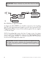
1
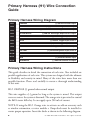
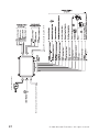
Matrix +1 Installation Guide NOTE: This product is intended for installation by a professional installer only! Any attempt to install this product by any person other than a trained professional may result in severe damage to a vehicle’s electrical system and components. ©2008 Directed Electronics, Vista, Ca. N3105X- 2008-12 The Bitwriter® (p/n 998T) requires chip version 2.4 or newer to program this unit. Bitwriter™, Code Hopping™, DEI®, Doubleguard®, ESP™, FailSafe®, Ghost Switch™, Learn Routine™, Nite-Lite®, False Alarm Control Technology™, Revenger®, Silent Mode™, Soft Chirp®, Stinger®, Valet®, Vehicle Recovery System®, VRS®, and Warn Away® are all Trademarks or Registered Trademarks of Directed Electronics, Inc. Contents Primary Harness (H1) Wire Connection Guide............................................................... 4 Primary Harness Wiring Diagram.............................................................................. 4 Primary Harness Wiring Instructions.......................................................................... 4 Door Lock Harness (H2), 3-PIN Connector................................................................. 11 Plug-In LED and valet/program switch......................................................................... 12 Programmer Interface, 3-Pin BLACK Plug............................................................... 13 Mounting the Control Center.................................................................................. 13 On-Board Dual-Stage Shock Sensor.............................................................................. 14 Optional Sensor Harness, 4-pin Connector................................................................... 15 Programming Jumper.................................................................................................... 16 Light Flash Jumper................................................................................................... 16 Bypassing Sensor Inputs................................................................................................. 17 System Features Learn Routine...................................................................................... 18 System Features Menus.................................................................................................. 21 Menu #1 - Basic Features.......................................................................................... 21 Menu #2 - Advanced Features.................................................................................. 22 Feature Descriptions...................................................................................................... 22 Menu #1 - Basic Features.......................................................................................... 22 Menu #2 - Advanced Features.................................................................................. 24 Transmitter/Receiver Learn Routine.............................................................................. 27 Transmitter Configurations........................................................................................... 30 Standard Configuration ........................................................................................... 30 Three-button configuration - Optional not included................................................ 30 Diagnostics.................................................................................................................... 31 Arm/Disarm Diagnostics.......................................................................................... 31 System Status Chirps................................................................................................ 31 Table of Zones.......................................................................................................... 32 Long Term Event History.............................................................................................. 32 Multi-Level Security Arming.......................................................................................... 33 Optional Vehicle Recovery System (VRS™)................................................................. 34 False Alarm Control Technology (FACT II ™)............................................................ 34 Rapid Resume Logic...................................................................................................... 34 Troubleshooting............................................................................................................. 35 3 © 2008 Directed Electronics- All rights reserved. Primary Harness (H1) Wire Connection Guide Primary Harness Wiring Diagram H1/1 ___ ORANGE H1/2 ___ WHITE H1/3 ___ WHITE/BLUE H1/4 ___ BLACK/WHITE H1/5 ___ GREEN H1/6 ___ BLUE H1/7 ___ VIOLET H1/8 ___ BLACK H1/9 ___ YELLOW H1/10 ___ BROWN H1/11 ___ RED ___ RED/WHITE H1/12 (-) 500 mA Armed Output (+)/(-) Selectable Light Flash Output (-) 200 mA Channel 3 Programmable Output (-) 200 mA Domelight Supervision Output (-) Door Trigger Input, Zone 3 (-) Instant Trigger Input, Zone 1 (+) Door Trigger Input, Zone 3 (-) Chassis Ground Input (+) Switched Ignition Input, Zone 5 (+) Siren Output (+) Constant Power Input (-) 200 mA Channel 2 Output Primary Harness Wiring Instructions This guide describes in detail the connection of each wire. Also included are possible applications of each wire. This system was designed with the ultimate in flexibility and security in mind. Many of the wires have more than one possible function. Please read carefully to ensure a thorough understanding of this unit. H1/1 ORANGE (-) ground-when-armed output This wire supplies a (-) ground as long as the system is armed. This output ceases as soon as the system is disarmed. The orange wire is pre-wired to control the 8618 starter kill relay. It can supply up to 500 mA of current. NOTE: If using the H1/1 Orange wire to activate an add-on accessory such as window automation, or voice module a 1Amp diode must be installed to ensure proper operation. Insert the diode as shown in the following diagram. 4 © 2008 Directed Electronics- All rights reserved. Important! Never interrupt any wire other than the starter wire. H1/2 WHITE (+/-) light flash output As shipped, the H1/2 WHITE wire should be connected to the (+) parking light wire. If the light flash polarity jumper is moved to the (-) position (see the Programming Jumper section of this installation guide), this wire supplies a (-) 200 mA output. Note: For parking light systems that draw 10 amps or more, the jumper must be switched to a (-) light flash output (see the Programming Jumpers section of this guide). P/N 8617 or a standard automotive SPDT relay must be used on the H1/2 light flash output wire. IMPORTANT! DO NOT connect this wire to a negative vehicle light flash wire before changing the programming jumper to the negative polarity position or damage to vehicle light circuit may occur. 5 © 2008 Directed Electronics- All rights reserved. H1/3 WHITE/BLUE 200 mA (-) channel 3 output This wire provides a (-) 200 mA output whenever the transmitter button(s) controlling channel three is pressed. This output can be programmed to provide the following types of output (see System Features Learn Routine section of this guide): • A validity output will send a signal as long as the transmission is received. • A latched output will send a signal continuously when the channel three button(s) is pressed and released. The signal will continue until channel three is pressed again. • A latched/reset with ignition output works similar to the latched output, but will also reset (output will stop) when the ignition is turned on and then off. • A 30 second timed output will send a signal for 30 seconds when channel three is pressed. This output can be shut off during the 30-second period by pressing Channel 3 again. • This output can also be programmed to provide a second unlock pulse when the unlock button is pressed a second time after disarming the system. This can be used to unlock the passenger doors when installing progressive door locks. 6 © 2008 Directed Electronics- All rights reserved. IMPORTANT! Never use this wire to drive anything but a relay or a low-current input! This transistorized output can only supply 200 mA, and connecting directly to a solenoid, motor, or other high-current device will cause the module to fail. H1/4 BLACK/WHITE (-) 200 mA domelight supervision output Connect the H1/4 wire to the optional domelight supervision relay as shown in the following diagram: IMPORTANT! This output is only intended to drive a relay. It cannot be connected directly to the domelight circuit, as the output cannot support the current draw of one or more bulbs. H1/5 GREEN (-) door trigger input Most vehicles use negative door trigger circuits. Connect the green wire to a wire showing ground when any door is opened. When connecting to newer model vehicles there is generally a need to use individual door triggers. See DirectFax document 1076 for wiring instructions. This wire will report Zone 3. NOTE: If using a door trigger wire that has a delay, Advanced Menu 2, feature 6 or the 998T Bitwriter can be used to turn Bypass Notification off. 7 © 2008 Directed Electronics- All rights reserved. H1/6 BLUE (-) instant trigger input This input will respond to a negative input with an instant trigger. It is ideal for hood and trunk pins and will report on Zone 1. It can also be used with Directed single-stage sensors. The H1/6 blue instant trigger wire can also be used to shunt sensors during operation of auxiliary channels or remote start. (See Bypassing Sensor Inputs section of this guide.) H1/7 VIOLET (+) door trigger input This type of dome circuit is used in many Ford products. Connect the violet wire to a wire that shows (+)12V when any door is opened. This wire will report Zone 3. NOTE: If using a door trigger wire that has a delay, Advanced Menu 2, feature 6 or the 998T Bitwriter can be used to turn Bypass Notification off. H1/8 BLACK (-) chassis ground connection Connect this wire to a clean, paint-free sheet metal location (driver kick panel) using a factory bolt that DOES NOT have any vehicle component grounds attached to it. A screw should only be used when in conjunction with a two-sided lock washer. Under dash brackets and door sheet metal are not acceptable ground points. It is recommended that all security components be 8 © 2008 Directed Electronics- All rights reserved. grounded at the same location. H1/9 YELLOW (+) ignition input Connect this wire to the (+) 12 volts ignition wire. This wire is pre-wired to the starter kill relay and must show (+) 12 volts with the key in RUN position and during cranking. Take great care that this wire cannot be shorted to the chassis at any point. \\\\\\\ H1/10 BROWN (+) siren output Connect this to the RED wire of the Revenger® siren. Connect the BLACK wire of the siren to (-) chassis ground, preferably at the same point you connect the control module’s BLACK ground wire. 9 © 2008 Directed Electronics- All rights reserved. H1/11 RED (+)12V constant power input Before connecting this wire, remove the supplied fuse. Connect to the battery positive terminal or the constant 12V supply to the ignition switch. NOTE: Always use a fuse within 12 inches of the point you obtain (+)12V. Do not use the 15 amp fuse in the harness for this purpose. This fuse protects the module itself. H1/12 RED/WHITE 200 mA (-) channel 2 output When the system receives the code controlling channel 2 for longer than 1.5 seconds, the RED/WHITE will supply an output as long as the transmission continues. This is often used to operate a trunk/hatch release or other relay/ driven function. IMPORTANT! Never use this wire to drive anything but a relay or a low-current input! The transistorized output can only supply 200 mA of current. Connecting directly to a solenoid, motor, or other high-current device will cause it to fail. 10 © 2008 Directed Electronics- All rights reserved. Door Lock Harness (H2), 3-PIN Connector H2/A H2/B H2/C ___ Green ___ Empty ___ Blue (-) Lock, (+) Unlock Output Unless Using 451M (-) Unlock, (+) Lock Output Important! The door lock outputs are low current and should not be attached directly to any high current device; they are only to be used to activate relays. For detailed instructions about connecting to the vehicle’s power door lock systems, refer to the Door Lock Wiring guide (Document No. 1041) available to authorized dealers only from the technical resources listed at the front of this guide. 11 © 2008 Directed Electronics- All rights reserved. Plug-In LED and valet/program switch The LED and the valet switch are incorporated into the Control Center. The LED line plugs into the WHITE 2-pin port, and the valet switch plugs in to the BLUE 2-pin port. NOTE: The onboard LED can be substituted with an optional outboard LED (P/N 8634 for Blue LED and 8633 for red LED). The LED fits into a 9/32 inch mounting hole. Be sure to check for clearance prior to drilling the mounting hole. You can also substitute an external valet switch for the Control Center valet switch (P/N 8631 is a 5-pack of these switches) Valet switch LED Important! With the Control Center more customers will want the Ghost switch coded disarm feature - make sure to check with the customer. 12 © 2008 Directed Electronics- All rights reserved. Programmer Interface, 3-Pin BLACK Plug The BLACK three-pin port connection is for programming the unit. When using the 998T Bitwriter®, it is possible to configure any and all of the programmable functions. For more information please refer to the guide packaged with the programmer. Mounting the Control Center The control center’s position should be discussed with the vehicle owner prior to installation, since it will be visible to to the vehicle’s operator. The best location for the Control Center is centered high on either the front or rear windshield. For optimal range, the antenna should be mounted vertically. It can be mounted horizontally in relation to the windshield or under the dashboard away from metal, but range will be diminished. Metallic window tint can also affect range, so this should be a consideration when determining the mounting location. After determining the best mounting location, follow these steps: 1. Clean the mounting area with a quality glass cleaner or alcohol to remove any dirt or residue. 2. Plug the Control Center cable into the Control Center. 3. Mount the Control Center using the supplied double-sided tape. 4. Route the Control Center cable to the control module and plug it into the four-pin antenna connector. 13 © 2008 Directed Electronics- All rights reserved. Important! To achieve the best possible range, DO NOT leave the control center cable bundled under the dash. Always extend the cable full length during installation, regardless of the antenna mounting location. CONTROL CENTER CABLE CONTROL CENTER On-Board Dual-Stage Shock Sensor There is a dual-stage shock sensor inside the control unit. Adjustments are made via the rotary control as indicated in the diagram. Since the shock sensor does not work well when mounted firmly to metal, we do not recommend screwing down the control module. The full trigger of the on-board shock sensor reports Zone 2. (See Table of Zones section of this guide.) Note: When adjusting the sensor, it must be in the same mounting location that it will be after the installation is completed. Adjusting the sensor and then relocating the module requires readjustment. 14 © 2008 Directed Electronics- All rights reserved. Optional Sensor Harness, 4-pin Connector The four-pin sensor harness is optional, and is not included with this unit. RED (+) 12V Constant and BLACK (-) Ground: These wires supply constant (+) 12 volts and ground to the optional sensor. BLUE/GREEN (-) Multiplex Input: These wires are multiplex inputs. If a (-) input of less than 0.8 seconds is supplied to either wire, the Warn-Away response will occur. A (-) input of longer than 0.8 seconds to either wire will initiate the triggered sequence and report Zone 4. 15 © 2008 Directed Electronics- All rights reserved. Programming Jumper Light Flash Jumper This jumper is used to determine the light flash output. In the (+) position, the on-board relay is enabled and the unit will output (+)12V on the WHITE wire, H1/2. In the (-) position, the on-board relay is disabled. The WHITE wire, H1/2, will supply a 200 mA (-) output suitable for driving factory parking light relays. NOTE: For parking light circuits that draw 10 amps or more, the jumper must be switched to a (-) light flash output. P/N 8617 or a standard automotive SPDT relay must be used on the H1/2 light flash output harness wire. Important! DO NOT connect the H1/2 light flash wire to a negative vehicle light flash wire before changing the programming jumper to the negative polarity position or damage to vehicle light circuit may occur. 16 © 2008 Directed Electronics- All rights reserved. Bypassing Sensor Inputs There are times when you need to temporarily bypass all sensor inputs to the unit, such as when remote starting the vehicle. Anytime an auxiliary channel output is used, all inputs are bypassed for 5 seconds. During the 5 second bypass period, ground can be supplied to the H1/6 Blue wire without triggering the unit. When the 5 second bypass period ends, if the unit sees ground on the H1/6 Blue wire, all trigger inputs except the door trigger input will remain bypassed until 5 seconds after ground is removed from the BLUE wire. The ignition input needs to be bypassed during remote start also. This can be done using the status and ignition output of a Directed Electronics remote engine starting unit as shown in the following diagram: Alarm system (-) During remote Yellow H1/9 ignition input start output Yellow ignition output from DEI remote start 17 Starter kill relay © 2008 Directed Electronics- All rights reserved. System Features Learn Routine The System Features Learn Routine dictates how the unit operates. Due to the number of steps, they have been broken up into two menus. It is possible to access and change any of the feature settings using the Valet/Program switch. However, this process can be greatly simplified by using the 998T Bitwriter. Any of the settings can be changed and then assigned to a particular transmitter, up to four, a feature called Owner Recognition. Each time that particular transmitter is used to disarm the system, the assigned feature settings will be recalled. Owner Recognition is only possible when programming the unit via the 998T Bitwriter. If the system was previously programmed using the 998T Bitwriter, the learn routine may be locked. If the siren generates one long chirp when attempting to program the unit, the learn routine is locked and must be unlocked using the 998T Bitwriter. 18 1. Open a door. (The H1/5 GREEN wire or the H1/7 2. Ignition. Turn the ignition on, then back off: (The 3. Select a Menu. Press and HOLD the Valet/Program switch: (The Valet/Program switch must be plugged into the blue port.) After three seconds the siren will chirp once indicating entry to the Basic Features Menu #1. If this is the menu you wish to access, release the button and go on to Step 4. If the button is not released, you will jump to the Advanced Features Menu #2 and the siren will chirp twice. Once you have selected the desired menu, release the Valet/Program button and then proceed to Step 4. VIOLET wire must be connected.) H1/9 YELLOW wire must be connected.) © 2008 Directed Electronics- All rights reserved. 4. 5. Select a Feature. Press and release the Valet/Program switch the number of times corresponding to the feature you wish to change. For example, to access the third feature, press and release the switch three times. Then press the switch once more and HOLD it. The siren will chirp the number of times equal to the step you have accessed. Program the Feature. While holding the Valet/ Program switch, you can toggle the feature on and off will select using the remote transmitter. Pressing will the one chirp setting. Pressing select the two chirp setting. (See Systems Features menus) ������� NOTE: The Valet pulse count feature (2-5) and the Channel three timed output (2-9) have five possible settings each. Pressing will toggle through all the two-chirp settings. 6. • • • • 19 ������� Release the Valet/Program Switch. ������� Once a feature is programmed: Other features can be programmed within the same menu. Another menu can be selected. The learn routine can be exited if programming is complete. © 2008 Directed Electronics- All rights reserved. To access another feature in the same menu: • Press and release the Valet/Program switch the number of times necessary to advance from the feature you just programmed to the next one you want to program. • Then press the Valet/Program switch once more and hold it. For example, if you just programmed the third feature in the menu and you would like to program the seventh feature in the menu, you would press and release the Valet/Program switch four times and then press it once more and hold it. The siren would chirp seven times to confirm access to the seventh feature. To select another menu: • Press and hold the Valet/Program switch. • After three seconds, the unit will advance to the next menu and the siren will chirp, indicating which menu has been accessed. For instance, if you just programmed some features in Menu #1 (Basic Features) and you wish to program a feature in Menu #2, you press and hold the Valet/Program button. After three seconds, the siren chirps twice indicating access to Menu #2. To exit the learn routine do one of the following: • • • • 20 Close the open door. Turn the ignition on. No activity for longer than 15 seconds. Press the Valet/Program switch too many times. © 2008 Directed Electronics- All rights reserved. System Features Menus Menu #1 - Basic Features Items in bold text have been programmed to the default setting at the factory. Feature Number One Chirp Setting Two-Chirp Setting 1-1 Active arming Passive arming 1-2 Chirps ON Chirps OFF 1-3 Ignition controlled door locks ON Ignition controlled door locks OFF 1-4 Active locking only Passive locking 1-5 Panic with ignition on No panic with ignition on 1-6 0.8 second door lock pulses 3.5 second door lock pulses 1-7 Forced passive arming ON Forced passive arming OFF 1-8 Automatic Engine Disable ON Automatic Engine Disable OFF 1-9 Armed When Driving (AWD) Vehicle Recovery System (VRS) Code Hopping™ on Code Hopping™ off 1-10 21 © 2008 Directed Electronics- All rights reserved. Menu #2 - Advanced Features Feature Number One Chirp Setting Two-Chirp Setting 2-1 Siren Horn honk 2-2 30-second siren duration 60-second siren duration* 2-3 False Alarm Control Technology ON FACT II ™ OFF 2-4 Progressive door trigger 2-5 Valet switch input: 1 pulse Valet switch input: 2-5 pulses 2-6 Bypass Notification ON Bypass Notification OFF 2-7 Ignition-controlled domelight ON Ignition-controlled domelight OFF 2-8 Single unlock pulse Double unlock pulse 2-9 Single lock pulse Double lock pulse Instant door trigger 2-10 Channel 3: Validity Channel 3: latched/latched, reset with ignition/30-second timed/ second unlock output* 2-11 Comfort Closure (On) (20 sec.) Comfort Closure (Off) *The Bitwriter allows programming from 1-180 seconds. *Second unlock is only available if Feature 2-8 is programmed to single pulse. Feature Descriptions The features of the system are described below. Features that have additional settings that can be selected only when programming with the 998T Bitwriter are indicated by the following icon: Menu #1 - Basic Features 1-1 ACTIVE/PASSIVE ARMING: When active arming is selected, the system will only arm when the transmitter is used. When set to passive, the system will arm automatically 30 seconds after the last door is closed. To alert the consumer of passive arming, the siren will chirp 20 seconds after the door is closed. This provides the consumer with an audible prior to the system actually arming. At the 30 second mark, the system will arm but the siren will not chirp. 1-2 Chirps ON/OFF: This feature controls the chirps that confirm the arming and disarming of the system. 22 © 2008 Directed Electronics- All rights reserved. 1-3 IGNITION CONTROLLED DOOR LOCKS ON/OFF: When turned on, the doors will lock three seconds after the ignition is turned on and unlock when the ignition is turned off. The 998T Bitwriter will display separate steps for ignition lock and ignition unlock. They can be programmed on or off independently. 1-4 ACTIVE/PASSIVE LOCKING: If passive arming is selected in step 1-1, then the system can be programmed to either lock the doors when passive arming occurs, or only lock the doors when the system is armed via the transmitter. Active locking means the system will not lock the doors when it passively arms. Passive locking means that the system will lock the doors when it passively arms. NOTE: Remember, when passive arming is selected, the unit will chirp 20 seconds after the last door is closed. The system does not actually arm or lock the doors until 30 seconds after the door has been closed. 1-5 PANIC WITH IGNITION ON: This step controls whether or not the Panic Mode is available with the ignition on. In some states, there are laws prohibiting a siren from sounding in a moving vehicle. This feature makes the system compliant with these regulations. 1-6 DOOR LOCK PULSE DURATION: Some European vehicles, such as Mercedes-Benz and Audi, require longer lock and unlock pulses to operate the vacuum pump. Programming the system to provide 3.5 second pulses, will accommodate the door lock interface in these vehicles. The default setting is 0.8 second door lock pulses. 1-7 FORCED PASSIVE ARMING ON/OFF: To use this feature, passive arming must be selected in step 1-1. When turned on, forced passive arming will ensure that the system will passively arm, even if a zone is left open or invalid. Forced passive arming occurs one hour after the ignition is turned off. 23 © 2008 Directed Electronics- All rights reserved. 1-8 AUTOMATIC ENGINE DISABLE (AED) ON/OFF: AED is a full-time, passive starter disable that works independently of the security system. When turned on, the orange, ground-when-armed output (H1/1) will go active 30 seconds after the ignition is turned off. The LED will flash at half its normal rate when the ignition is turned off to indicate that AED is active and will interrupt the starter in 30 seconds. AED does not occur in Valet mode and can be bypassed using the emergency override procedure. The transmitter can also be used to disarm AED. 1-9 ARMED WHILE DRIVING/VEHICLE RECOVERY SYSTEM: In the default setting (Armed While Driving), the system can be armed with the ignition on. When armed, the ground-when-armed is not active and the sensors are bypassed. The door triggers will remain active. If programmed to the Vehicle Recovery System (VRS®) setting, VRS® will be activated. 1-10 CODE-HOPPING™ ON/OFF: The system uses a mathematical formula to change its code each time the transmitter and receiver communicate. This makes the group of bits or “word” from the transmitter very long. The longer the word is, the easier it is to block its transmission to the unit. Disabling the Code-Hopping™ feature lets the receiver ignore the Code-Hopping™ part of the transmitted word. As a result, the unit may have better range with Code-Hopping™ off. Menu #2 - Advanced Features 2-1 SIREN/HORN HONK: The system can be programmed to output pulses instead of a continuous output when the system is triggered. This is useful to honk the factory horn in applications where a siren is undesirable. Remember that the unit is only capable of supplying 1 amp of current. A relay will be required to interface with most factory horn systems. 2-2 SIREN DURATION 30/60 SECONDS: It is possible to program the unit to sound for 30 or 60 seconds during the triggered sequence. Some states have laws regulating how long a security system can sound. When using the 998T Bitwriter, the siren can be programmed to sound for any length of time ranging from 1 to 180 seconds. Using the SELECT button of the 998T Bitwriter will adjust the siren duration in one second increments. 24 © 2008 Directed Electronics- All rights reserved. 2-3 FALSE ALARM CONTROL TECHNOLOGY (FACT II™) ON/OFF: FACT II stops repeated triggering of the same zone. If one zone is triggered three times in one hour, that zone is bypassed for one hour, starting from the time of the third trigger. During that hour, if the system detects a trigger on that zone again, the system resets the one hour timer. If one hour passes and the zone has not triggered again, the zone is activated and can trigger the system again. FACT II monitors sensor inputs and the door trigger, but does not bypass the ignition trigger at any time. If FACT II is turned off, the system will respond to repeated triggers on the sensor inputs and will do so indefinitely. Some states have laws regulating how many times a security system can trigger before it is considered a nuisance and the vehicle is towed away. 2-4 PROGRESSIVE DOOR TRIGGER ON/OFF: The system responds to a door trigger input with a progressive response. When the door is opened with the system armed, the siren will chirp 10 times prior to the full triggered sequence. The door trigger is still treated as an instant trigger and closing the door quickly will not prevent a full triggered sequence from occurring. If the progressive door trigger is programmed off, the full siren output will occur the moment the door is opened. 2-5 VALET PULSE COUNT ONE TO FIVE PULSES: The system can be programmed to count the number presses of the valet button before disarming the security system or VRS®. The factory default setting is one pulse. The unit can be set for two to five pulses using the two-chirp setting to select the pulse count. Ghost Switch Option: For added security, the GRAY wire on the two-pin Valet/Program can be connected to any switch in the vehicle that provides a positive (+) momentary pulse. 2-6 Bypass Notification ON/OFF: when programmed on, any active zone input to the system during arming will generate a bypass notification chirp. When programmed OFF, no bypass notification chirps will be generated if any zone is active during arming. 2-7 Ignition-controlled DOMELIGHT SUPERVISION ON/OFF: If turned on, the system will turn on the domelight for 30 seconds when the ignition is turned off. The optional domelight supervision feature must be installed. 25 © 2008 Directed Electronics- All rights reserved. 2-8 DOUBLE PULSE UNLOCK ON/OFF: Some vehicles require two pulses on a single wire to unlock the doors. When the double pulse unlock feature is turned on, the BLUE H2/C wire will supply two negative pulses instead of a single pulse. At the same time, the GREEN H2/A wire will supply two positive pulses instead of a single pulse. This makes it possible to directly interface with double pulse vehicles without any extra parts. 2-9 Double/Single Pulse Lock: Some vehicles require two pulses on a single wire to lock the doors. When the double pulse lock feature is turned on, the BLUE H2/C wire will supply two positive pulses instead of a single pulse. At the same time the GREEN H2/A wire will supply two negative pulses instead of a single pulse. This makes it possible to directly interface with double pulse vehicles without any extra parts. 2-10 CHANNEL 3 VALIDITY/LATCHED/LATCHED RESET WITH IGNITION/30 SECOND TIMED/SECOND UNLOCK OUTPUT: Channel 3 can be programmed for these output configurations. The unit is set to the default validity output. To change the configuration use the two-chirp setting to toggle to the different configurations. 2-11 COMFORT CLOSURE: The system can be programmed to close the windows when the system is armed. A 20-second output starts 200mS after the button pulse. The comfort closure output will be cancelled if the last button is pressed. If programmed ON, the lock output wire will provide this function. ������� ������� NOTE: Comfort closure is deleted if one-time bypass is activated. 26 © 2008 Directed Electronics- All rights reserved. Transmitter/Receiver Learn Routine The system comes with two transmitters that have been taught to it. The system can store up to four different transmitter codes in memory. Use the following learn routine to add transmitters to the system or to change button assignments if desired. If the system was previously programmed using the 998T Bitwriter, the learn routine may be locked. If the siren generates one long chirp when attempting to program the unit, the learn routine is locked and must be unlocked using the 998T Bitwriter before proceeding. 1. Open a door. (The GREEN wire, H1/5, or the VIOLET, H1/7 must be connected.) 2. Turn the ignition on. (The YELLOW wire, H1/9 must be connected.) 3. Select the receiver channel: Press and release the Valet/Program button the number of times necessary to access the desired channel. NOTE: If adding a remote, a button must be taught to the unit in the Channel 1 or Channel 5 position prior to programming other channels. Press and hold the Valet/Program button once more. The siren will chirp and the LED will blink the number of times corresponding to the channel accessed. 27 © 2008 Directed Electronics- All rights reserved. Channel Number Function Wire Color 1 Arm/Disarm 2 Panic only 3 Silent Mode/Remote Valet/Trunk Release 4 Remote Start or other accessories 5 Arm only 6 Disarm only 7 Auto-learn standard configuration* (four-button transmitter) 8 Auto-learn three-button configuration* 9 Delete all transmitters RED/WHITE WHITE/BLUE *NOTE: For Auto Learn Configurations, see Transmitter Configurations section of this guide. 4. Press the transmitter button: While holding the Valet/ Program button, press the button from the transmitter that you wish to assign to the selected channel. The unit will chirp indicating successful programming. It is not possible to teach a transmitter button to the system more than once. Channels #2, 5, 6: Channels 2, 5, and 6 are used to assign the arm, disarm and panic functions to separate buttons on the remote control. Teaching a button to Channel 5 or Channel 1 erases some information about that remote from memory, and auxiliary functions that are desired may have to be reprogrammed. Channel #9: If any button from a known transmitter is programmed to Channel 9, all transmitters will be erased from memory and the system features will revert to the default settings. This is useful in cases where the one of the customer’s transmitters is lost or stolen. This will erase any lost or stolen transmitters from the system’s memory. It can also be used to start from scratch if the transmitter buttons were programmed incorrectly. 28 © 2008 Directed Electronics- All rights reserved. 5. Release. Once the code is learned, the Valet/Program button can be released. To exit the learn routine: One long chirp indicates that Learn Routine has been exited. Learn Routine will be exited if any of the following occurs: • • • • 29 Ignition is turned off. Door is closed. Valet/Program button is pressed too many times. More than 15 seconds elapse between steps. © 2008 Directed Electronics- All rights reserved. Transmitter Configurations The transmitters can be programmed with the standard or three-button configurations by using the Auto Learn functions in the Transmitter/Receiver Learn Routine. Standard Configuration When programmed for standard configuration, the transmitter buttons are assigned to the following functions: operates Arm only operates Disarm only operates Channel 2 and Silent Mode operates Panic ������� ������� ������� and operate Channel 3 Three-button configuration - Optional not included ������� ������� operates Arm/Disarm ������� ������� operates Channel 2 and Silent Mode operates Panic ������� and operate Channel 3 ������� NOTE: Multi Level Security Arming feature is not available with the threebutton. 30 ������� © 2008 Directed Electronics- All rights reserved. Diagnostics The system’s microprocessor monitors and reports all active and violated zones when arming and disarming. LED flashes indicate the active or violated zone; siren chirps indicate system status. Arm/Disarm Diagnostics The number of siren chirps will indicate the status of the alarm when arming and disarming. For information on which zone is active or has been violated refer to the Table of Zones. System Status Chirps Action Number of Chirps Description Arm 1 System armed Arm 1 (3 second delay), 1 System armed with Bypass Notification Disarm 2 System disarmed Disarm 4 System disarmed with Tamper Alert Disarm 5 System disarmed FACT II active 31 © 2008 Directed Electronics- All rights reserved. Table of Zones Zone No. Trigger type Input description 1 Instant H1/6 BLUE - Connect to optional hood/trunk pins. 2 On-board shock sensor Heavy impact detected by the on-board shock sensor. 3 Two-stage, progresses from Door switch circuit. H1/5 GREEN or H1/7 VIOLET warning to full alarm 4 Multiplexed Input BLUE and GREEN wires of optional sensor plug. Inputs shorter than 0.8 seconds will trigger a Warn Away response, while inputs longer than 0.8 seconds will instantly trigger a full alarm sequence and report Zone 4. Ignition input. H1/9 YELLOW. 5 Two-stage (similar to doors) NOTE: The Warn Away® response does not report on the LED. Long Term Event History The system stores the last two full triggers in memory. These are not erasable. Each time the unit sees a full trigger, the older of the two triggers in memory will be replaced by the new trigger. To access long term event history: 1. With the ignition off, press and hold the Valet/Program switch. 2. Turn on the ignition. 3. Release the Valet/Program switch. 32 © 2008 Directed Electronics- All rights reserved. 4. Press and release the Valet/Program switch within 5 seconds. The LED will flash in groups indicating the last two zones that triggered the unit. The LED will flash for one minute or until the ignition is turned off. NOTE: The Warning Zone triggers are not stored to memory and will not be reported. Multi-Level Security Arming Multi-Level Security arming allows the operator to select which inputs and sensors are active during a particular arming cycle. For a full description of Multi-Level Security Arming operation for testing purposes refer to the owner’s manual. 33 © 2008 Directed Electronics- All rights reserved. Optional Vehicle Recovery System (VRS) VRS is an optional feature designed to disable a vehicle during a carjacking event. It must be programmed in the features menu and the Failsafe Starter Kill must be installed for it to work properly. For operational instructions when testing VRS refer to the owner’s manual. False Alarm Control Technology (FACT II™) FACT II requires that you change the way you test the system, as FACT II will bypass an input zone for 60 minutes. If the system detects the same zone triggering three times AND the triggers are spaced less than an hour apart, the system will bypass that input zone for 60 minutes. If that zone does not attempt to trigger the system during the 60-minute bypass period, the zone’s monitoring will begin again at the end of the hour. If it does attempt to trigger while bypassed, the 60-minute bypass starts over again. Disarming and rearming the system does not reset FACT II. The only way to reset FACT II is for the 60minutes to pass, without a trigger, or for the ignition to be turned on. This allows the system to be repeatedly triggered, disarmed and rearmed, while still allowing FACT II to bypass a faulty zone. When disarming the system, 5 chirps indicate FACT II is activated. The LED will report the zone that has been bypassed. (See Table of Zones section of this guide.) Rapid Resume Logic Rapid Resume Logic ensures that the when the system is powered up it will return to the same state it was in when power is disconnected. For a full description of Rapid Resume Logic refer to the owner’s manual. 34 © 2008 Directed Electronics- All rights reserved. Troubleshooting Starter kill doesn’t work. • Is the correct starter wire being interrupted? If the car starts when the starter kill relay is completely disconnected, the wrong starter wire has been cut and interrupted. • YELLOW wire is not connected to true ignition. It is connected to an accessory circuit. Shock sensor doesn’t trigger the alarm. • Has the FACT II system been triggered? If so, you will hear five chirps when disarming. To check this, turn the ignition key on and off to clear the FACT II from memory, and then retest the shock sensor. For a detailed description of FACT II, see Owner’s Guide. Door input does not immediately trigger full alarm. Instead, I hear chirps for the first three seconds. • That’s how the progressive two-stage door input works! This is the instant response feature of this system. Even if the door is closed immediately, the system provides an instant trigger by chirping, and the progressing to a constant siren. Closing the door triggers the system, but opening the door does not. • Have you correctly identified the type of door switch system? This happens often when the wrong door input has been used. 35 © 2008 Directed Electronics- All rights reserved. System will not passively arm until it is remotely armed and then disarmed. • Are the door inputs connected? Is a blue wire connected to the door trigger wire in the vehicle? Either the green H1/5 or the violet H1/7 should be used instead. Door input does not respond with the progressive trigger, but with immediate full alarm. • What zone does the LED indicate? If the LED indicates that the impact sensor caused the trigger, the sensor may be detecting the door opening. Reducing the sensitivity or relocating the sensor can often solve this problem. If the LED indicates that the door caused the trigger, you may have programmed the progressive door trigger off. (See Feature 2-4 in the Feature Descriptions section of this guide.) The Valet button doesn’t work. • Is it plugged into the correct socket? Check the System Features Learn Routine for the programmed Valet pulse count. Status LED doesn’t work. • Make sure that it is plugged in. (See Plug-In Harnesses section of this guide.) Is the LED plugged into the correct socket? 36 © 2008 Directed Electronics- All rights reserved. 37 © 2008 Directed Electronics- All rights reserved. Blue 2 pin plug, valet switch plug from 6111T 6111T control center White 2 pin LED plug from 6111T N3105X 2008-12 Vista, CA 92081 www.directed.com © 2008 Directed Electronics.—All rights reserved.