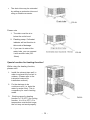
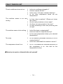
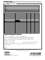
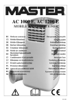
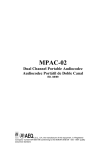
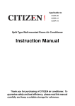
1
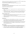
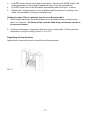
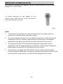
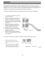
Installation and Operation Manual
Room Air Conditioners
Portable Heat Pump Range
Local Air Conditioners
ECO15P
Register your air conditioner
Model information can be found on the CE
label.
Please register your product online at
www.ecoair.org. For your future
convenience, record the model information
below.
____________________________________
MODEL NUMBER
____________________________________
SERIAL NUMBER
____________________________________
PURCHASE DATE
Congratulations!
You have purchased the very latest in room air conditioner technology. Your
new EcoAir high efficiency room air conditioner will give you many years of
dependable service. Many features have been built into your EcoAir portable
air conditioner to assure quiet operation, the best circulation of cool, dry air,
functional controls, and the most economical operation.
Table of contents
BS Plug Wiring ..............................................................................................................
1
Specification ..................................................................................................................
2
Before Use ....................................................................................................................
3
Product Description .......................................................................................................
5
Installation .....................................................................................................................
6
Mounting of the Exhaust Pipe .......................................................................................
7
Installation of Carbon Filter............................................................................................
8
Operation of Control Panel ............................................................................................
9
Self Diagnosis ................................................................................................................ 12
Drainage ........................................................................................................................
13
Maintenance ..................................................................................................................
15
Fault Checklist ...............................................................................................................
16
Order Form ....................................................................................................................
17
Disposal
When using this air conditioner in the European countries, the
follow information must be followed:
DISPOSAL: Do not dispose this product as unsorted waste.
It is prohibited to dispose of this appliance in domestic household waste. For
disposal:
A) Contact your local council for disposal.
B) The manufacture will take back the old appliance for disposal when you replace with a new
product.
C)
Old products contain valuable resources, which should be recycled as scrap metal.
Wild disposal of waste in forests and landscapes endangers your health when hazardous
substances leak into the ground-water and find their way into the food chain.
BS Plug Wiring
Wiring Instructions: Should it be necessary to change the plug please
note the wires in the mains lead are coloured in accordance with the
following code:
BLUE - NEUTRAL
BROWN – LIVE
GREEN AND YELLOW - EARTH
As the colours of the wires in the mains lead of this appliance may not
correspond with the coloured markings identifying the terminals in your plug,
proceed as follows:
1. The BLUE wire is the NEUTRAL and must be connected to the terminal
which is marked with the letter N or coloured BLACK.
2. The BROWN wire is the LIVE and must be connected to the terminal which
is marked with the letter L or coloured RED.
3. The GREEN/YELLOW is the EARTH and must be connected to the
terminal which is marked with the letter E or
or coloured GREEN or
GREEN/YELLOW.
4. Always ensure that the cord grip is positioned and fastened correctly.
If a 13A (BS 1363) fused plug is used it must be fitted with a 13A fuse. If in
doubt consult a qualified electrician.
Wiring for a 13 Amp Plug (BS1363)
Please note. The Earth Terminal is marked with the letter E or
- 1 -
Earth Symbol.
SPECIFICATION
Model no.
ECO15P
15000 BTU/hr
4395watts
11600 BTU/hr
3400watts
Cooling capacity
Heating capacity
Power/Ampere
consumption for cooling
Power/Ampere
consumption for heating
Air volume (max. speed)
Humidity removal capacity
Power supply
1655 W/ 7.5A
1280 W/ 5.9A
550m3/h
1.3L/hour
220-240V~ 50Hz
Compressor
rotary
Sound Pressure (Lp)
50/52/57 dB(A)
Sound Power (Lw)
58/60/65 dB(A)
Refrigerant
R410A (560g)
Fan speed
3
Timer
1̚24 hours
Cooling: 18 ~ 32oC
Heating: 7 ~ 25oC
Ø 142x1500mm
Working temperature
Exhaust pipe
Net Weight
33.5 kgs
Gross Weight
38.5 kgs
Net Dimension (WxHxD)
422x825x443 mm
Gross Dimension (WxHxD)
490x875x575 mm
REMARK:
1. Measuring condition for above is as per EN 14511 :
Cooling – DB=35°C , WB=24°C
Heating – DB=20°C , WB=12°C
DB = temperature of dry bulb = room temperature,
WB = temperature of wet bulb = relative humidity.
- 2-
BEFORE USE
GENERAL SAFETY
•
ONLY USE IN THE UPRIGHT
POSITION ON A FLAT LEVEL
SURFACE AND AT LEAST 50cm
FROM ANY OBJECTS (Fig 1&4).
•
DO NOT PLACE OBJECTS ON THE
UNIT
OR
RESTRICT
AIR
INLET/OUTLET (FIG. 2).
•
CLOSELY
SUPERVISE
ANY
CHILDREN AND PETS WHEN UNIT
IS IN USE.
•
FIG. 1
THIS
APPLIANCE
IS
NOT
INTENDED FOR USE BY PERSONS
(INCLUDING CHILDREN) WITH
REDUCED PHYSICAL, SENSORY
OR MENTAL CAPABILITIES, OR
LACK OF EXPERIENCE AND
KNOWLEDGE,
UNLESS
THEY
HAVE BEEN GIVEN SUPERVISION
OR INSTRUCTION CONCERNING
USE OF THE APPLIANCE BY A
PERSON
RESPONSIBLE
FOR
THEIR
SAFETY.
CHILDREN
SHOULD BE SUPERVISED TO
ENSURE THAT THEY DO NOT PLAY
WITH APPLIANCE.
FIG. 2
ELECTRICAL SAFETY
•
FOR INDOOR USE ONLY.
•
SWITCH OFF AND UNPLUG WHEN
NOT IN USE.
•
DO NOT USE IN HUMID OR WET
ENVIRONMENTS (FIG 3)
•
DO NOT PULL THE UNIT ALONG
BY THE CORD.
•
IF THE ELECTRICAL SUPPLY
CORD IS DAMAGED, IT MUST BE
REPLACED BY AN ELECTRICIAN
OR SIMILARLY QUALIFIED
PERSON, TO AVOID HAZARD.
FIG.3
- 3 FOR MAXIMUM EFFICENCY
•
Do not exceed the recommended
room size.
•
Take into the account the number of
people or equipment used in the
room as these produces heat and
will reduce the cooling
effectiveness.
•
Avoid opening doors frequently.
•
Keep curtains or blinds closed
during the warmest part of the day.
•
Keep filters clean.
•
Once room has reached the desired
conditions, reduce temperature and
ventilation setting.
•
Locate air conditioner where airflow
is not obstructed to increase air
flow.
•
Close any air grills, windows or
ducting to avoid cooled air escaping
during use.
- 4
FIG.4
PRODUCT DESCRIPTION
Front
Back
FIG.5
FIG.6
1.
Control Panel
5.
Air filter
2.
Air vent
6.
Air inlet
3.
Handle
7.
Cord storage
4.
Caster
8.
Outlet of exhaust air
9.
Water stopper / outlet of condensed
water
Accessories
10.
Exhaust hose.
11.
PVC strip - for filling the open
window space
12.
PVC strip - for filling the open
window space
13.
PVC strip (with hole) - for filling the
open window space and with hole for
connection to tie-in
14.
Outward adaptor - for insertion over
hose and into PVC strip (or into hole
in the wall/window).
15.
Cover for outward adaptor
16.
Remote control
17.
Active carbon filter
18. Tube for continuous drainage
FIG.7
- 5 INSTALLATION
Installation of the exhaust pipe
The unit is a portable air conditioner that may be moved from room to room.
1. Using the PVC strip
FIG.8
•
•
•
Offer PVC strips to the window gap and adjust to size if necessary.
Connect one end of the exhaust pipe to outlet of exhaust air and the other end with
the outward adapter.
Feed the exhaust hose to the PVC strip as shown and slide window across so that
PVC strip is held securely. Note: Take care to maintain protection against intruders.
2. Using the adaptor
:DOORU:LQGRZ
2XWZDUG
DGDSWRU
FIG.10
50cm
FIG.9
•
•
•
Cut a 151mm diameter hole in the wall or window.
Feed exhaust hose through the window or wall and attach the threaded adaptor from
the outside as shown.
When not in use, plug the hole with the cover provided.
- 6 MOUNTING OF THE EXHAUST PIPE
•
•
•
Use only the hose provided and
clip exhaust hose and unit adaptor
to the back of the air conditioner.
FIG.11
Avoid kinks and bends in the
exhaust hose as this will cause
expelled moist air to build up
causing the unit to overheat and
shut down. Fig 11 & 12 show
correct position.
FIG.12
The hose may be extended from
300mm to 1500mm but for
maximum efficiency use the
shortest length possible.
FIG.13
FIG.14
- 7 INSTALLATION OF CARBON FILTER
1.
Remove the filter frame from the
unit.
FIG.15
2.
Separate the filter fixer from the
filter frame.
3.
Remove the active carbon filter
from its plastic bag.
4.
Insert the active carbon filter into
the filter frame.
5.
Fix the filter by reassembling the
fixer onto the filter frame.
6.
Re-fit the filter frame inside the unit.
- 8 OPERATION OF THE CONTROL PANEL
Control panel
FIG.16
1.
2.
3.
4.
5.
6.
7.
8.
9.
10.
11.
12.
Fan Speed button
Timer button
Display window
Receiver for remote control
Heating operation indicator(optional)
Mode (function) button
Auto operation indicator
Cooling operation indicator
Fan operation indicator
“Temperature up” button
“Temperature down” button
Power indicator
13.
14.
15.
16.
17.
18.
19.
20.
21.
22.
23.
“Water Full” indicator
ON/OFF (power) button
Sleep function button
TiO2(UV light)/Ionizer button (optional)
Indicator for compressor
TiO2(UV light)/ionizer indicator (optional)
Sleep operation indicator
Timer operation indicator
Low ventilation indicator
Medium ventilation indicator
High ventilation indicator
Turning ON/OFF
Adjust the louvers to desired angle and position.
Press ON/OFF button, the unit will start to work. If the ambient temperature is
z higher than 23oC, the unit will work in cool mode.
z higher than 20oC but below or equal to 23oC, the unit will work in ventilation model.
z below 20oC, the unit will work in heat function (This is for cooling & heating models
only)
- 9 Indicators of the functions in progress come on at the same time. NOTE! The display window
shows the ambient room temperature from 0oC to 50oC.
To turn the unit off, press ON/OFF button again, then close the air louvers.
Setting mode/function
Press MODE button to select required working mode: automatic, cooling, fan or heat (Heat is
only available for heating & cooling models.)
Indicator of the selected mode comes on.
Setting Temperature
1. Press 'Temperature up' or 'Temperature down' button to regulate the temperature you
desire.
2. The display window will show the temperature you set as you press 'Temperature up' or
'Temperature down' button. Otherwise, it will always show the ambient temperature.
3. The pre-setting temperature of this machine is: 24oC for cooling, 20oC for heating.
Setting ventilation speed
1.
Press SPEED button to choose the fan speed you need, high, medium or low. The sign
of high, low or medium fan will light on at the same time.
2.
If the unit is in AUTO mode, it will choose the fan speed automatically according to the
ambient temperature.
Setting timer
1.
Press TIMER button to set the operating hours you desire (1 to 24 hours, the sign of
timer will light on). The window will show the hour(s) you set as you press TIMER
button. If the timer button is not pressed, the unit will work continuously.
2.
By pressing the timer but without turning on the other functions, you can PRE-SET the
time for the machine to work. For example, if you press the timer to '2', the unit will
work automatically after 2 hours.
Sleep function
1.
In cooling mode, by pressing the SLEEP button, the set temperature will increase 1oC
at the 1st hour, another 1 oC at the second hour, then keeps at that temperature.
2.
In heat mode, by pressing the SLEEP button, the set temperature will descend 1oC at
the 1st hour, another 1 oC at the second hour, then keeps at that temperature.
- 10 -
3.
4.
5.
In SLEEP mode, the fan will be kept at low speed. Re-press the SLEEP button, the
setting temperature and ventilation speed will return to the pre-selected one.
In SLEEP mode, the unit will shut down automatically after running for 12 hours.
Please note, the sleep function is not available while the machine is working in fan
mode. Only available in Cooling or Heating mode.
Heating function (This is optional, only for cool & heat model.)
1. When using Heat Pump, the ambient warm air is recycled and use to heat the area
where it is required. The Exhaust Pipe must be fitted firmly to allow the cold air to
be removed outside.
2. Continuous drainage is compulsory while the unit is in heat mode. Working ambient
temperature range for heating function is 7 to 25oC.
Regulating air flow direction
Adjust the air louvres by hand to control the air flow direction.
FIG. 17
- 11 IMPORTANT DIAGNOSIS NOTE
This machine is equipped with diagnosis function. Please contact us if your machine
displays “E1” or “E2” codes.
The above warnings will also appear on your
remote control. Note that this control will require 2
AAA size batteries to operate.
FIG.18
NOTE:
1.
To prolong the compressor's life, after switching off the unit, please wait for a
minimum of 3 minutes before switching on again.
2.
The cooling system will switch off if the ambient temperature is lower than the set
temperature. The fan, however, keeps working on the set level. If the ambient
temperature rises above the selected level, the cooling will return to work.
3.
The heating will switch off if the ambient temperature is higher than the set
temperature. The fan keeps working on the set level. As the ambient temperature
drops below the selected level, the heating will return to work.
4.
This machine is equipped with ANTI-FROST function. While using the heating
function during low temperature, sometimes the heating will stop for a while in order
to melt the frost. As this occurs, just wait for the heating to return to work.
- 12 DRAINAGE
During the process of cooling, some water will be extracted from the air into the unit. Most of
the water will be evaporated by the coil for maximum efficiency. However in very warm
temperature or humid condition, excessive condensation may occur and will require water
drainage when tank is full. If the tank is full, both of the compressor and motor will stop. The
“water full” sign will light ON, also the machine will beep as reminder.
To make the cooling work again, please empty the water by one of the following ways:
1. Turn off the air conditioner and avoid
moving it when full.
2. Position a container (a water tray for
example) underneath the drain hole.
3. Remove the drain knob & rubber plug
from the drain hole and allow the water
to drain out.
4. When the container is almost full,
replace the rubber plug in the drain
hole and empty the water tray.
5. Repeat until the unit is emptied.
6. Replace the rubber plug and tighten
the drain knob firmly.
FIG.19
7. Switch on the unit - the full water or
compressor operating indicator should
not be flashing.
If you wish to operate the unit without the need to empty the water tank, please:
•
Remove the drain knob and
rubber plug and retain for future
use.
•
Connect the drain tube supplied
to the water outlet as shown and
locate the other end into a drain.
FIG.20
- 13 •
The drain tube may be extended
by adding an extension tube and
using a suitable connector.
FIG.21
Please note
1. The drain must be at or
below the outlet level.
2. Flashing comp / ‘full water’
indicator will not function in
this mode of drainage.
3. If you want to extend the
water tube, you can connect
it with another tube (OD:
18mm)
FIG.22
Special caution for heating function!
While using the heating function,
please note:
1. Install the exhaust pipe well, in
order to exhaust the cool air to
outdoor. (Please refer to the
instruction manual for
installation method.)
2. Fix the drainage to be
continuous one (i.e. drain the
water by water tube). This is
compulsory for use in heating
mode.
3.
Working range for heating
function is 7 to 25oC (for cooling
function, it is 18 to 32oC). For
temperature outside this range,
the unit may not work properly.
FIG.23
- 14 MAINTENANCE
Always unplug the air conditioner from the mains before cleaning.
To maximize the efficiency of the air conditioner, clean regularly.
Cleaning the housing
Use a soft, damp cloth to wipe the body clean.
Never use aggressive chemicals, gasoline, detergents, chemically treated cloths, or
other cleansing solutions. These all could possibly damage the cabinet.
Cleaning the filter
Use a vacuum cleaner or tap the filter lightly to remove loose dust and dirt from the
filters and then rinse thoroughly under running water (no hotter than 40oC).
Dry thoroughly before replacing.
Note: Never operate the unit without the filters.
End of season storage
•
Drain any water in the unit then
switch the unit to fan mode for a few
hours to thoroughly dry the inside.
•
Clean or change the filter
•
Unplug and store the power cord as
shown
•
Cover the cord storage
•
Place in the original carton or cover
for storage.
&RYHUIRU
FRUG
FRPSDUWPHQW
3RZHU
FRUG
FIG.24
- 15 FAULT CHECK LIST
The air conditioner does not run
y
y
y
y
Is the air conditioner plugged in?
Is there a power failure?
Is the comp / ‘full water’ indicator flashing?
Is the room temperature below the set
temperature?
The machine seems to do little y
cooling
Is there direct sunshine? (Please put down
the curtain.)
Are too many windows or doors open?
Are there too many people in the room?
Is there something in the room producing lots
of heat?
y
y
y
The machine seems to do nothing.
y
y
y
Is the filter dusty, contaminated?
Is the air intake or output blocked up?
Is the room temperature below your selected
temperature?
Too noisy
y
Is the machine positioned unevenly so as to
create vibration?
Is the floor underneath the machine uneven?
y
The compressor doesn’t run.
y
Is so, it is possible the overheat protection of
the compressor is on. Just wait for the
temperature to drop.
侀Never try to repair or dismantle the unit yourself
-
16 -
ORDER FORM
Post Order Form
Your Details
Company Name:
Name:
Address:
Post code:
Telephone:
Mobile:
Fax / Email:
Model Number
Description of Item
Quantity
Unit Price
£Amount
Filters
15P-108 & 109
Real Filter & Fixer
£14.99
15P-110
Side Filter
£14.99
15P-116
Filter Track
£8.99
15P-806
Active Carbon Filter
£12.99
15P-205
Remote Control
£29.99
15P-141
Exhaust Hose (1.5m)
£24.99
15P-137
Tube for continuous drainage
£6.99
15P-817
Extension drainage tube (1m)
£5.99
15P-135
Water Bung
£6.99
Exhaust Accessories
Other Accessories
15P-308
Caster Wheels
£5.99
15P-144 & 15P-145 & 15P-146
PVC window Kit
£29.99
15P-142 & 15P-143
Round Window Connector Set
£14.99
Sub Total
Standard Delivery (Free)
Next Day Delivery (Call)
Total
Payment Details (Please tick one below)
Ƒ
Visa Ƒ
Credit
or Debit Card
Ƒ
or Cheque
Ƒ
Ƒ Solo Ƒ Visa Electron Ƒ
Card Number: ƑƑƑƑƑƑƑƑƑƑƑƑƑƑƑƑƑƑƑƑƑƑƑ
Name on card:ƑƑƑƑƑƑƑƑƑƑƑƑƑƑƑƑƑƑƑƑƑƑƑ
Issue Date: ƑƑ / ƑƑ
Expiry Date: ƑƑ / ƑƑ
Issue No (where applicable): ƑƑ / ƑƑ
Card Security No: ƑƑƑ(Last 3 digits on the signature strip on the reverse of your card)
Master Card
Customer Signature:
...............................................................
Name:
Date:
* Price includes VAT and shipping to UK mainland only (except Scottish Highlands and remote areas)
*Note: Please see page 5 for your reference.
Fax Form To Us
Fax: 0845 388 9313
Mail Form To Us
EcoAir Unit 7 Propeller Park,
400 North Circular Road, London NW10 0AB
Tel: 0845 388 0005
Order Today By Fax, Post Or Via Online
More Information: http://www.ecoair.org
ONE (1) YEAR LIMITED WARRANTY
SAVE THIS WARRANTY INFORMATION
EcoAir guarantees this product free from defects in materials and
workmanship for a period of one (1) year from the date of purchase, limited
to parts only.
Faults arising from a faulty installation is specifically excluded.
This unit must be operated under conditions as recommended, at voltages
indicated on the unit. Any attempts made to service or modify the unit by
unqualified technician, will render this WARRANTY VOID. The actual
product may differ slightly from the illustration. This warranty is in addition to,
and does not affect, your statutory rights.
For after sales needs, please visit www.ecoair.org/service or email
[email protected] or contact 0845 388 0007
We recommend that you note the details of your purchase below and retain
your original proof of purchase receipt with this manual. Keep these documents
safe in the event of a warranty claim. Please register your product online at
www.ecoair.org.
Date of purchase:
_____________________________
Purchased from (Dealer Name): _____________________________
Retailer name:
_____________________________
Model number:
_____________________________
Serial number:
_____________________________
Date of installation:
_____________________________
Copyright Reserved
C170