1
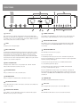
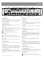
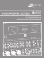
IN600
AV SYSTEM CONTROLLER
INSTALLATION AND OPERATION MANUAL
IMPORTANT SAFETY INFORMATION
PRÉCAUTIONS DURANT UTILISATION
1.
Read these instructions.
1.
LISEZ ces instructions.
2.
Keep these instructions.
2.
Tenez ces instructions.
3.
Heed all warnings.
3.
Notez tous les avertissements.
4.
Follow all instructions.
4.
Suivez toutes les avertissements.
5.
Do not use this apparatus near water.
5.
N’utilisez pas ce produit près de l’eau (la piscine, la plage, le lac, etc.).
6.
Clean only with dry cloth.
6.
Nettoyez seulement avec une étoffe sèche.
7.
Do not block any ventilation openings. Install in accordance with the
manufacturer’s instructions.
7.
Ne bloquez aucuns troux de ventilation. Installez en accord avec
les instructions du manufacturier.
8.
Do not install near any heat sources such as radiators, heat registers,
stoves, or other apparatus (including amplifiers) that produce heat.
8.
N’installez près aucunes sources de chaleur comme radiateurs,
registres de chaleur, fours ou les autres équipements (y compris
amplificateurs) qui produisent la chaleur.
9.
Do not defeat the safety purpose of the polarized or grounding-type
plug. A polarized plug has two blades with one wider than the other.
A grounding type plug has two blades and a third grounding prong.
The wide blade or the third prong are provided for your safety. If the
provided plug does not fit into your outlet, consult an electrician for
replacement of the obsolete outlet.
9.
Ne défaites pas le but de sécurité de la fiche polarisée ou base-type.
Une fiche polarisée a deux tranchants avec un plus large que l’autre.
Une fiche de base type a deux a deux tranchants et une troisième
pointe de base, le tranchant large ou la troisième pointe est fourni
pour votre sécurité. Si la fiche donnée ne conforme pas votre prise
de contact, consultez un électricien pour remplacement de la prise
de contact obsolète.
10. Protect the power cord from being walked on or pinched particularly
at plugs, convenience receptacles, and the point where they exit from
the apparatus.
11. Only use attachments/accessories specified by the manufacturer.
12. Use only with the cart, stand, tripod, bracket, or table
specified by the manufacturer, or sold with the
apparatus. When a cart is used, use caution when
moving the cart/apparatus combination to avoid injury
from tip-over.
13. Unplug this apparatus during lightning storms or when
unused for long periods of time.
14. Refer all servicing to qualified service personnel. Servicing is required
when the apparatus has been damaged in any way, such as powersupply cord or plug is damaged, liquid has been spilled or objects have
fallen into the apparatus, the apparatus has been exposed to rain or
moisture, does not operate normally, or has been dropped.
15. This appliance shall not be exposed to dripping or splashing water and
that no object filled with liquid such as vases shall be placed on the
apparatus.
16. Plug this apparatus to the proper wall outlet and make the plug to be
disconnected readily operable.
17. Main plug is used as disconnected device and it should remain readily
operable during intended use. In order to disconnect the apparatus from
the mains completely, the mains plug should be disconnected from the
mains socket outlet completely.
10. Protegez le cordon de secteur contre être marchée dessus ou pincez
en particulier aux fiches, aux douilles de convenance, et au point où ils
sortent de l’appareil.
11. Seulement utilisez attachements/accessoires spécifiés par le
manufacturier.
12. Utilisez seulement avec un chariot, un stand, un
trépied, un support ou une table indiquée par le
manufacturier, ou vendue avec l’appareil. Quand un
chariot est utilisé, faites attention en déplaçant la
combinaison d’appareil/chariot pour éviter de se
déséquilibrer.
13. Arrachez la fiche du dispositif durant éclair et orage ou quand
pas utilisé pour longues périodes de temps.
14. Référez au personnel qualifié de service pour toutes réparations.
La réparation est donnée quand le système a été endommagé à
n’importe façon, par exemple un fil ou une fiche endommagé(e)
de la source d’alimentation. Avoir été exposé à pluie ou humidité,
n’opère pas normalement, ou avoir été tombé.
15. L’appareil ne doit pas être exposé aux écoulements ou aux
éclaboussures et aucun objet ne contenant de liquide, tel qu’un vase,
ne doit être placé sur l’objet.
16. Branchez l’appareil à une source appropriée et faire que la prise à
débrancher soit facilement accessible.
18. WARNING: To reduce the risk of fire or electric shock, do not expose this
apparatus to rain or moisture.
17. La prise du secteur ne doit pas être obstruée ou doit être facilement
accessible pendant son utilisation. Pour être complètement déconnecté
de l’alimentation d’entrée, la prise doit être débranchée du secteur.
19. An appliance with a protective earth terminal should be connected to a
mains outlet with a protective earth connection.
18. AVERTISSEMENT: Pour éviter le risque d’incendie ou de chocs
électriques, ne pas exposer cet appareil à la pluie ou à l’humidité.
19. Un appareil avec la borne de terre de protection doit être connecté au
secteur avec la connexiion de terre de protection.
INTRODUCTION AND CONTENTS
The Innovation series from AMAV is a huge step forward in the interfacing and
management of audio and visual sources. Integrating a host of smart, high end
features in a compact package that offers the end user extremely simple control
over their complex audio visual system. The Innovation series is as ground
breaking as it is simple to operate.
The IN600 takes the Innovations series concept to the next level in terms
of flexibility and complete system control. The IN600 features an on board
mic/line mixer, 6 AV source inputs, and 6 balanced XLR outputs so it can be
configured as a 5.1 front end. The IN600 also features RS232 for projector
control and logic output for screen up/down control. With the IN600 we give the
AV integrator the ability to use the IN600 for full room AV control or it can be
interfaced with third party control systems if desired. The IN600 offers untold
flexibility for AV control in an extremely user friendly package.
INTRODUCTION
3
FRONT PANEL
4
REAR PANEL
5
INSTALLATION
6
SETUP / SOFTWARE
7–9
INTERNAL ADJUSTMENTS
10
BLOCK DIAGRAM
11
DIMENSIONS
12
SPECIFICATIONS
13
AUS, EUR, USA
Copyright 21st Aug 2008
REV A 21st Aug 2008
REV B 9th Dec 2008
REV C 28th May 2009
REV D 15th April 2010
REV E 3rd June 2010
WARNING!
TO PREVENT FIRE OR SHOCK HAZARD, DO NOT USE THE PLUG WITH AN EXTENSION CORD, RECEPTACLE OR
OTHER OUTLET UNLESS THE BLADES CAN BE FULLY INSERTED TO PREVENT BLADE EXPOSURE.
TO REDUCE THE RISK OF FIRE OR ELECTRIC SHOCK, DO NOT EXPOSE THIS APPLIANCE TO RAIN OR MOISTURE.
TO PREVENT ELECTRICAL SHOCK, MATCH WIDE BLADE PLUG TO WIDE SLOT, FULLY INSERT.
CAUTION
RISK OF ELECTRIC SHOCK
DO NOT OPEN
The lightning flash with arrowhead symbol,
within an equilateral triangle, is intended
to alert the user to the presence of
uninsulated “dangerous voltage” within
the product’s enclosure that may be of
sufficient magnitude to constitute a risk
of electric shock to persons.
WARNING: TO REDUCE THE RISK
OF ELECTRIC SHOCK, DO NOT
REMOVE COVER (OR BACK).
NO USER SERVICEABLE PARTS INSIDE.
REFER SERVICING TO QUALIFIED
SERVICE PERSONNEL.
The exclamation point within an equilateral
triangle is intended to alert the user to
the presence of important operating and
maintenance (servicing) instructions in the
literature accompanying the appliance.
Rating plate and caution marking are marked on the back enclosure of the apparatus
IN600 INSTALLATION AND OPERATION MANUAL
PAGE 3
FRONT PANEL
4
3
7
11
9
10
8
12
1
2
6
1 GAIN TRIM
This control is used to adjust the input gain and affects both the XLR and the
RCA inputs. The input gain can be adjusted by +/- 15dB. This allows a wide rage
of program sources to be set up with optimum gain structure. With the gain trim
in the centre position, the boost/cut is set to 0dB.
2 LEVEL
Controls the level of the input signal.
3 INPUT STATUS LEDS
Each input has an LED status indicator. The LED is green when there is signal
present and red if the signal is approaching clip. If the LED begins to light red
this would indicate the internal signal level is 6dB before clip. Note that the
front panel level control is post status LED and as such, the status LED is NOT
affected by the level control. If an input channel is clipping use the gain control to
adjust the correct amount of input level.
4 INPUT SELECTED LEDS
Each input can be switched on or off seperately via PC or RS485. This LED
indicates when the when the channel is selected.
5 AV SOURCE MASTER
This pot controls the level of the selected AV source.
13
14
5
9 SOURCE SELECT LEDS
The LED above the switch indicates when the AV source is being routed to the
audio and video outputs. OFF indicates no source is routed to the outputs.
10 PROJECTOR POWER SWITCH
This switch is used to control a projector. Pushing this button will send data
control commands out the PROJECTOR COMMS connector and trigger the
screen relays.
11 PROJECTOR POWER LED
This LED indiactes the state of the projecter.
Projector Power LED state
1. LED flashing means the projector has sent a command and assumes the
projector is now warming up or cooling down. If the button is pushed again while
the LED is flashing nothing happens.
2. LED on means the projector has been sent an ON command and the
necessary warmup period has elapsed.
3. LED off means the projector has been sent an OFF command and the
necessary cool down period has elapsed.
Projector communication is only one way so the actual state of this projector
may not match the state of the LED. If this happens, set the projector to off and
then switch of the IN600. Switch the IN600 on and now both projector and LED
should be off.
6 MIC/LINE MASTER
This pot controls the overall mixed level of the Mic/Line sources.
12 POWER ON LED
The AMAV logo will be illuminated when the unit is on.
7 MASTER VOLUME LEDS
These LED’s indicate the position of the volume control. They do not indicate the
strength of the signal.
8 SOURCE SELECT SWITCHES
These switches select the input that is routed to the audio and video outputs.
OFF will not route any source to the output.
PAGE 4
13 USB Socket
This is a Type B USB connector used to connect the I600 to a PC.
14 COMMS LED
This LED indicates when data is sent or revceived via PC or RS485.
IN600 INSTALLATION AND OPERATION MANUAL
REAR PANEL
16
15 14
17
5
7
6
4
1 CHANNEL INPUTS
Each channel has two inputs:
XLR input - This is a balanced input. It accepts mic or line level signals depending
on the adjacent gain switch position. The XLR will also have +15V phantom power if
selected on the adjacent switch.
RCA input - This is an unbalanced line level input. The two RCA sockets are
summed to mono internally.
2 P/P (PHANTOM POWER)
15V phantom power is available for condenser or electret microphones on the XLR
input when this switch is in the ‘ON’ position.
3 MIC / LINE
These two switches control the sensitivity of the XLR input. In the ‘MIC’ position the
XLR input is suitable for use with microphones; in the ‘LINE’ position the XLR input
is suitable for use with a balanced line level signal.
Note: Both MIC/LINE switches must be in the same position for
correct operation of the balanced input.
Note: The MIC/LINE switches only affect the XLR input.
4 5.1 OUTPUTS
The 5.1 OUTPUT XLRs provide balanced line level signal.
Note: When wiring the XLR output as unbalanced, Pin2 should be
wired as hot and Pin1 should be wired as ground/shield. Do not wire Pin3.
5 5.1 INPUTS
These are the RCA unbalanced line level audio inputs for the DVD1 and DVD2
sources.
6 STEREO (2CH) INPUTS
These are the RCA unbalanced line level audio inputs for the AUX1/AUX2/PC1/PC2
sources.
7 SEND 2-CH TO
These DIP switches allow the STEREO INPUTS to be routed to the CENTRE output
and or the SUB output as well as still going to the LEFT and RIGHT outputs. The
LEFT and RIGHT outputs are summed together for the CENTRE and SUB outputs.
The down position means the audio is routed, the default setting is off (UP).
8 SEND MIC/LINE MIX TO
These DIP switches allow the MIC/LINE INPUTS to be routed to the CENTRE (C)
output, LEFT output (L) and RIGHT output (R) or not. The down postion means the
audio is routed. Up position means the audio is not routed to any output. The default
setting is on (down).
9
10
8
13
2
11
1
12
3
9 VIDEO INPUT
These are RCA unbalanced 75ohm composite video inputs for the DVD1/DVD2/
AUX1/AUX2 sources.
10 VIDEO OUTPUT
These are the RCA unbalanced 75ohm composite video outputs. OUT1 and OUT2
output the same signal but they are individually buffered. These outputs only output
the signal from DVD1/DVD2/AUX1/AUX2 sources if selected.
11 VGA INPUT
These are high densisty 15pin D connector VGA inputs for the DVD1/DVD2/PC1/
PC2 sources.
12 VGA OUTPUT
This is the high densisty 15pin D connector VGA output. This output only outputs the
signal from DVD1/DVD2/PC1/PC2 sources if selected.
13 DVD SOURCES
These DIP switches are used to set the DVD source type. Selecting COMP means
the DVD video signal is coming in on the composite VIDEO connector and is
swithced to the composite VIDEO output. Selecting VGA means the DVD video
signal is coming in on the VGA connector and is switched to the VGA output.
This is needed to make sure the correct data codes are sent on the RS485 and
PROJECTOR COMMS.
14 RS485
This 3.81mm pluggable connector socket is provided for external control of the
IN600 using RS485 or for connecting an Australian Monitor control panel.
15 SCREEN
This 3.81mm pluggable connector output is used to trigger projector screen
controls. These are voltage free contacts that short to COM when activated. They
are activated by the powering of the projector. When the projector is switched on
the screen down contacts are activated. When the projector is switched off the
screen up contacts are activated. The relays stay closed for the period set in the
configuration software.
16 PROJECTOR COMMS
This 9 pin D-connector is for sending data to a projector.
17 IEC MAINS INPUT SOCKET
This is a standard IEC 3 pin socket (IEC320-C14). It accepts a standard IEC mains
cable, provided. The fuse draw contains the mains fuse and a spare. The mains fuse
is a time lag (slow blow) HRC 20mm x 5mm fuse. The ratings are:
230V/240V model 200mA
120V model 500mA
Always replace the fuse with one of the same value and type.
Note: Always disconnect power to the amplifier before replacing fuses.
IN600 INSTALLATION AND OPERATION MANUAL
PAGE 5
INSTALLATION
All installation work should be done with the power disconnected. The following information will help with installation. After installation is complete power up in the
following order:
1. All the sources
2. IN600
3. All amplifiers
POWER CONNECTION
BREAK OUT CABLE
Component video can be used on the IN600
by using a VGA break out cable. A break out
cable is required for all devices. There is no
internal VGA to component conversion within
the IN600. (ie. the lines are simply switched and
the component signals require sync on them, eg
sync on green). You can not use a VGA source in
to a component source out for example.
Ensure the mains voltage supply matches the rear of the IN600 (+/- 10%).
Ensure that all system grounds (earth) are connected to a common point. Avoid
powering equipment within a system from multiple power sources that may be
separated by large distances. This will eliminate ground loops that are heard
as 50/60Hz humming or buzzing in speakers and seen as moving or stationary
bars on video equipment.
OUTPUT CONNECTION
Video
Video outputs are on either unbalanced RCA sockets (composite) or 15 pin high
density female connectors D-connectors (VGA). The maximum cable length for
composite video is typically less than 3m for shielded wire and 10m for coaxial
before signal degradation. This will depend on the cable quality.
There are two composite outputs for running to 2 different monitors without the
need for an external distribution amplifier.
VGA pin out
1 Red out
2 Green out
3 Blue out
4 Monitor ID 2 in
5 Ground
6 Red return
7 Green return
8 Blue return
9 no pin
10 Sync return
11 Monitor ID 0 in
12 Monitor ID 1 in
13 Horizonal Sync out
14 Vertical Sync out
15 reserved (monitor ID 3)
Only pins 1,2,3,5,6,7,8,10,13,14 are used in the IN600.
INPUT CONNECTIONS
Audio
All the inputs are unbalanced RCA sockets. Unbalanced RCA wiring should be
keep as short as possible. Typically less than 3m.
Video
Video inputs are on either unbalanced RCA sockets (composite) or 15 pin high
density female connectors D-connectors (VGA). The maximum cable length for
composite video is typically less than 3m for shielded wire and 10m for coaxial
before signal degradation. This will depend on the cable quality.
RS485 CONNECTIONS
The RS485 data port is on a 5.08mm pluggable connectors. Twisted pair
cabling should be used When connecting RS485 devices, such as CAT3, CAT5,
CAT5e or CAT6 UTP cabling. RS485 data networks should be wired in a ‘daisy
chain’ configuration with a maximum of 32 devices in the chain. The IN400 is
not terminated so may be inserted anywhere in the data network. If the IN600 is
being used at the end of a chain, a 120ohm (characteristic impedance of UTP)
terminating resistor should be connected between the + and - connections.
The maximum length of the chain is 1200m (4000’).
PAGE 6
IN600 INSTALLATION AND OPERATION MANUAL
RS485 COMMANDS
Data: 19200, 8N1
All ASCII characters
The commands are pure ASCII. So a hex value of 0xA5 (decimal 165) is sent as ASCII ‘A’ ‘5’, or 0x41 0x35.
eg Command !04GR01??<CR> is sent as a hex string 0x21 0x30 0x34 0x47 0x52 0x30 0x31 0x3F 0x3F 0x0D
GET COMMANDS
OBJECT
DATA
RESPONSE
DATA
!04SR01XX<CR>
XX-volume setting 00-FF (00 is min)
!04GR01??<CR>
Get source volume
!08GR01??<CR>
Get mic/line volume
!08SR01XX<CR>
XX-volume setting 00-FF (00 is min)
!04GL01??<CR>
Get source mute state
!04SL01YY<CR>
YY-ON,OF,FL (On,Off, Flashing)
!08GLXX??<CR>
Get mic/line enabled state
XX-mic/line channel 01-04
!08SLXXYY<CR>
XX-mic/line channel 01-04; YY-ON,OF,FL (On,Off, Flashing)
!10GLXX??<CR>
Get source/projector state
XX-source channel 01-06, 07off, 08-projector
!10SLXXYY<CR>
XX-source channel 01-06, 07-off, 08-projector; YY-ON,OF,FL
(On,Off, Flashing)
SET COMMANDS
These commands are used to set values on the IN600. Good programming techinique should update control system visual info on the feedback responses not the ACK
message, see Feedback table.
OBJECT
DATA
ACK
NACK
!04SR01XX<CR>
Set source volume
XX-volume setting 00-FF (00 is min)
!04A<CR>
!04N<CR>
!08SR01XX<CR>
Set mic/line volume
XX-volume setting 00-FF (00 is min)
!04SB01SH<CR>
Mute source
!08SBXXSH<CR>
Enable/Disable Mic/Line
!10SBXXSH<CR>
Select source/toggle projector
!08A<CR>
!08N<CR>
!04A<CR>
!04N<CR>
XX-mic/line channel 01-04
!08A<CR>
!08N<CR>
XX-source channel 01-06, 07-off, 08-projector
!10A<CR>
!10N<CR>
FEEDBACK RESPONSES
These messages are sent from the IN600 when changes occur in the IN600. This includes RS485 Set commands as well as front panel changes.
OBJECT
DATA
*01SR01XX<CR> When the source volume changes
XX-volume setting 00-FF (00 is min)
*02SR01XX<CR> When the mic/line volume changes
XX-volume setting 00-FF (00 is min)
*01SL01YY<CR>
When the source mute state changes
YY-ON,OF,FL (On,Off, Flashing)
*02SLXXYY<CR>
When the Mic/Line enabled stated changes
XX-mic/line channel 01-04; YY-ON,OF,FL (On,Off, Flashing)
*03SLXXYY<CR>
When the selected source or projector changes
XX-source channel 01-06, 07-off, 08-projector; YY-ON,OF,FL (On,Off, Flashing)
IN600 INSTALLATION AND OPERATION MANUAL
PAGE 7
SETUP / SOFTWARE
The IN600 software come included on a CD ROM. The IN600 software will work on any windows XP or later operating system. Installing the software is easy insert the
CD and run the setup.exe file. Follow the prompts.
You should close down the software before disconnecting the IN600 from the USB port.The IN600 can be safely connected and disconnect from the USB port at anytime
when the software is not running.
2
4
3
1
5
6
Main Window
1 Mic Level
This is the software equivalent of the MIC/LINE MASTER pot on the front panel.
2 Enable
These check boxes allow you to enable or disable the 4 mic/line channels
individually. Selected channels will have there INPUT SELECTED LEDS on, shown
on the front panel. The labels can be changed in the Configuration/Set Input
Names menu item.
3 Source Level
This is the software equivalent of the AV SOURCE MASTER pot on the front panel.
4 Source Select
These radio buttons toggle the selected source. The labels can be changed in the
Configuration/Set Input Names menu item.
PAGE 8
5 Turn Projector On/Off buttons
These buttons control the operation of the projector if one is connected to the
IN600. The codes that are sent to the projector can be set in the Configuration/
Set Projector Codes menu option. Only one button button is highlighted at a time
indicating the state of the projector. If the Turn Projector On button is highlighted
then a Turn Projector Off code must have been sent at some time previously. If
the Turn Projector Off button is highlighted then a Turn Project On code must have
been sent at some time previously.
Note: Projector comms is uni-directional only. Commands are sent to
the projector, no commands are recieved. It is possible that the
Projector can be out of sync with the IN600. If this happens the IN600
should be set to show the projector is off and then the projector should
be manually switched off.
6 Status bar
The status bar shows the state off the computer and software connection. The first
word (USB Disconnected or USB Connected) indiactes if the IN600 is connected
to the USB port and the operating system has recognized it. There is no software
control associated with this indication. The second word (IN600 Offline or IN600
Online) indicates if the setup software is communicating with the IN600. If it is
online then changes made in the software are immediately seen on the IN600.
This is a real time connection. If it is offline then changes made in the software
wont change the IN600 until a connection is made. When a connection is made
the user is given the option to upload the software configuration. Connection is
made in the Configuration/Connect menu item.
IN600 INSTALLATION AND OPERATION MANUAL
SETUP / SOFTWARE CONTINUED
1
2
3
4
File menu
This menu contains the standard Windows File options.
1 Open
Opens a .in6 file which contains a previously save configuration of the software.
Opening a file will overwrite your current configuration. If the IN600 is Online then
opening a file will load the contents straight up to the IN600.
2 Save
This will prompt you to save the file with the name of the open file. If no file has
been opened you can save it as any name.
3 Save As
Allows you to save the configuration of the set software as a .in6 file.
4 Exit
Closes the application.
IN600 INSTALLATION AND OPERATION MANUAL
PAGE 9
SETUP / SOFTWARE CONTINUED
1
2
3
4
3
Configuration menu
1 Set Projector Codes
This menu item will open the Projector Setup window.
2 Set Input Names
Allows you to set the names of the Mic/Line inputs and the AV sources. These are
stored in the EEPROM of the IN600 itself and is limited to 8 charaters.
3 Set Power Up Values
This button opens a window to configure the power up settings. The power up
settings is the way the unit will be set after powering up. The window asks if
you would like to download the current power up configuration stored in the
IN600 or store the current configuration of the software as the default power up
configuration. Note that changes made to the unit from either the software or the
front panel are not automatically saved and recalled when turning off the IN600 or
exiting the software.
5 Connect/Disconnect
This menu item will be showing either Connect or Disconnect.
Connect
If it is showing Connect then selecting it will cause the software to try and connect
to the IN600. When a connection is made the user is given the option to upload the
software configuration or download the actual IN600 configuration to the software.
Uploading software will overwrite the setting on the IN600. Downloading from the
IN600 will overwrite the software settings. Once connected, changes made in the
software are immediately seen on the IN600. This is a real time connection. The
status bar at the bottom of the main window will show IN600 Online.
Disconnect
If it is showing Disconnect then selecting it will cause the software to go Offline.
If it is offline then changes made in the software wont change the IN600 until a
connection is made. The status bar at the bottom of the main window will show
Offline.
4 Turn Project Off / Turn Projector On
These correspond to the buttons in the main window. See ‘Main Window’ above.
PAGE 10
IN600 INSTALLATION AND OPERATION MANUAL
SETUP / SOFTWARE CONTINUED
Project Setup window
This window allows you to set the parameters of the RS232 port used to connect to a projector. You can set all the parameters of the communication protocol; Baud Rate,
Parity, No of Data Bits, No of Stop Bits.
1
2
3
1 Projector Timeouts
3 Screen
This is the number of seconds (integer values only) that the IN600 will wait before
allowing another command to be set to the projector when an On/Off command
is sent. This allows time for the projector to warm up or cool down. Consult the
projectors manufacturer data for information on warm up and cool down times.
Integer values between 1 and 300 are accepted.
This is the number of seconds the SCREEN up/down relay contacts will stay closed
for controlling the screen motor. It is accurate to 0.1 seconds and accepts values
from 0.1 to 25.5.
2 Projector Strings
RS-232 DB-9 Male Pinout
These are the strings that will be sent to projector. When the projector power
button is pushed on the IN600 the on or off code is sent. When a source is
selected the corresponding video format code is sent.
GND
5
9
4
Table 1
DVD1
DVD2
depends on setting of back panel DIP switch
AUX1
AUX2
Video code set
PC1
PC2
VGA code sent
8
TxD
3
PIN 2: Receive Data
PIN 3: Transmit Data
7
RxD
2
PIN 5: Signal Ground
6
1
A maximum of 20 characters can be sent. \x will cause the next 2 characters to be
read as a hex value. eg \x20 will send hex value 20 (ASCII-space).
The test buttons allow these strings to be sent to the projector. The IN600 must be
Online for these to work.
IN600 INSTALLATION AND OPERATION MANUAL
PAGE 11
INTERNAL ADJUSTMENTS
1
2
3
The following routing configurations can be made inside the IN600. Access to the inside the the IN600 should only be performed by a qualified person.
1 Mic/Line HPF
Each of the 4 mic/line inputs has a 150Hz HPF. Moving the jumper to the
IN position will enable the filter. The factory default is OUT.
2 Mic/Line mix to...
The mic/line mix can be sent to the the surround sound left and right and/or the
sub output. There are 3 jumpers with two postions, on or off. The default setting
is off.
3 Stereo channels to surround output
The stereo mixed signal can be routed to the rear surround left and right outputs.
There are 2 jumpers with two positions. The left input will go to the left surround
output when the left jumper is set and the right input will go to the right surround
output when the right jumper is set. The default setting is off.
PAGE 12
IN600 INSTALLATION AND OPERATION MANUAL
BLOCK DIAGRAM
IN600 INSTALLATION AND OPERATION MANUAL
PAGE 13
DIMENSIONS
PAGE 14
IN600 INSTALLATION AND OPERATION MANUAL
SPECIFICATIONS
Line Audio THD
Noise Floor
Frequency Response (+/-3dB)
Gain (trim centre)
Headroom
<0.5%
-90dBu
20-20kHz
XLR Mic 45dB
XLR Line 0dB
RCA line 12dB
RCA switched 0dB
15dBu
Video
VGA
Video
Video follows Audio switching
Comms
Type
Baud Rate
No of Data Bit
Parity
No of Stop Bits
RS485
19200
8
None
1
Power Consumption (max)
30VA
Thermal output
SIZE (WXHXD)
High speed RGB+Sync switching
Composite 75ohm Buffered outputs
1/8th power 100W (341.2Btu/hr)
482 x 88 x 270mm
19.” x 3.5” x 9.82”
NET WEIGHT
4.25kg
9.4lb
SHIPPING WEIGHT
6.5kg
14.3lb
SHIPPING DIMENSIONS (WXHXD)
IN600 INSTALLATION AND OPERATION MANUAL
520 x 190 x 360mm
20.5” x 7.5” x 14.2”
PAGE 15
AUSTRALIA AND NEW ZEALAND
www.australianmonitor.com.au
SYDNEY
MELBOURNE
ADELAIDE
AUCKLAND
(NSW SALES)
(VIC & TAS SALES)
(SA & NT SALES)
(NZ SALES)
1 Clyde Street
Silverwater
NSW 2128
Private Bag 149
Silverwater NSW 1811
Phone: (02) 9647 1411
Fax: (02) 9648 3698
Email:
[email protected]
22/277
Middleborough Road
Box Hill VIC 3128
PO Box 151 Blackburn
South VIC 3130
Phone: (03) 9890 7477
Fax: (03) 9890 7977
Email:
[email protected]
31 Walsh Street
Thebarton
SA 5031
PO Box 157
Hindmarsh SA 5007
Phone: (08) 8352 4444
Fax: (08) 8352 4488
Email:
[email protected]
9C Piermark Drive
Albany 0752
New Zealand
PO Box 300-512
Albany 0752
Phone: (09) 415 9426
Fax: (09) 415 9864
Email:
[email protected]
CANBERRA
BRISBANE
PERTH
(ACT SALES)
(QLD SALES)
(WA SALES)
1st Floor,
Campion Street
Deakin ACT 2600
PO Box 109
Deakin West ACT 2600
Phone: (02) 6260 4544
Fax: (02) 6260 4744
Email: gordon.anderson@
hillssvl.com.au
42 Commercial Road
Fortitude Valley
QLD 4006
PO Box 2578 Fortitude
Valley BC QLD 4006
Phone: (07) 3852 1312
Fax: (07) 3252 1237
Email:
[email protected]
3/11 Howe Street
Osborne Park WA 6017
PO Box 1281
Osborne Park BC
WA 6916
Phone: (08) 9204 0200
Fax: (08) 9244 3783
Email:
[email protected]
EUROPE / ASIA / MIDDLE EAST
www.australianmonitor.com.au
INTERNATIONAL SALES
1 Clyde Street Silverwater NSW 2128 Australia
Private Bag 149 Silverwater NSW 1811
Phone: + 61 2 9647 1411
Fax: + 61 2 9748 2537
Email: [email protected]