1
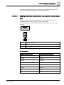
SPC42xx/43xx/52xx/53xx/63xx
Installation & Configuration
Manual
Version 3.2
A6V10276959
18.11.2011
Siemens AB
Security Products
Copyright
Copyright
Technical specifications and availability subject to change without notice.
© Copyright Siemens AB
We reserve all rights in this document and in the subject thereof. By acceptance of
the document the recipient acknowledges these rights and undertakes not to
publish the document nor the subject thereof in full or in part, nor to make them
available to any third party without our prior express written authorization, nor to
use it for any purpose other than for which it was delivered to him.
Edition: 18.11.2011
Document ID: A6V10276959
2
Siemens AB
Security Products
A6V10276959
18.11.2011
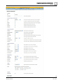
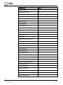
Table of contents
1
Meaning of symbols ......................................................................................... 10
2
Security ............................................................................................................. 11
2.1
Target group ....................................................................................................... 11
2.2
General safety instructions ................................................................................. 11
2.2.1
General information ............................................................................ 11
2.2.2
Transport ............................................................................................. 12
2.2.3
Setup ................................................................................................... 12
2.2.4
Operation ............................................................................................ 12
2.2.5
Service and maintenance ................................................................... 13
2.3
Meaning of written warning notices .................................................................... 13
2.4
Meaning of hazard symbols ............................................................................... 13
3
Directives and standards ................................................................................ 15
3.1
EU directives ...................................................................................................... 15
3.1.1
Conformity to EN50131 Standard ....................................................... 15
4
Technical Data .................................................................................................. 19
4.1
SPC4000 ............................................................................................................ 19
4.2
SPC5000 ............................................................................................................ 21
4.3
SPC6000 ............................................................................................................ 23
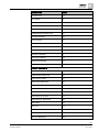
5
Introduction ...................................................................................................... 26
6
Mounting system equipment .......................................................................... 27
6.1
Mounting a G2 enclosure ................................................................................... 27
6.2
Mounting a G3 enclosure ................................................................................... 29
6.2.1
Mounting a Back Tamper Kit .............................................................. 30
6.3
Battery installation .............................................................................................. 34
6.4
Mounting a keypad ............................................................................................. 35
6.5
Mounting an expander........................................................................................ 35
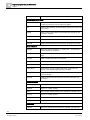
7
Controller hardware ......................................................................................... 36
8
Door Controller ................................................................................................. 39
9
Wiring the system ............................................................................................ 40
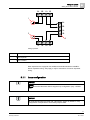
9.1
Wiring the X-BUS interface ................................................................................ 40
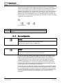
9.1.1
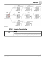
Loop configuration .............................................................................. 41
9.1.2
Spur configuration ............................................................................... 42
9.1.3
Star and multi-drop configuration........................................................ 43
9.1.3.1
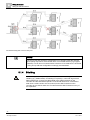
Examples of correct wiring .................................................................. 46
9.1.3.2
Examples of incorrect wiring ............................................................... 47
9.1.4
Shielding ............................................................................................. 48
9.1.5
Cable Map ........................................................................................... 49
9.2
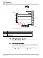
Wiring of branch expander ................................................................................. 49
9.3
Wiring the system ground................................................................................... 50
9.4
Wiring the relay output ....................................................................................... 50
9.5
Wiring the zone inputs ........................................................................................ 51
3
Siemens AB
Security Products
A6V10276959
18.11.2011
9.6
Wiring an external SAB bell ................................................................................ 54
9.7
Wiring an internal sounder ................................................................................. 54
9.8
Installing plug-in modules ................................................................................... 55
10
Powering up the SPC controller ..................................................................... 56
10.1
Powering from battery only ................................................................................. 56
11
Keypad user interface ...................................................................................... 57
11.1
SPCK420/421 ..................................................................................................... 57
11.2
11.1.1
Introduction ......................................................................................... 57
11.1.2
Using the keypad interface ................................................................. 59
11.1.3
Data entry on the keypad .................................................................... 61
SPCK620/623 ..................................................................................................... 62
11.2.1
Introduction ......................................................................................... 62
11.2.2
LED description ................................................................................... 64
11.2.3
Viewing mode description ................................................................... 65
11.2.4
Function keys in idle state ................................................................... 66
12
Starting the system .......................................................................................... 68
12.1
Engineer modes ................................................................................................. 68
12.1.1
12.2
Engineer PINs ..................................................................................... 68
Programming tools ............................................................................................. 68
12.2.1
Fast Programmer ................................................................................ 69
12.3
Configuring start-up settings .............................................................................. 69
12.4
Creating system users ........................................................................................ 70
12.5
Programming the portable ACE ......................................................................... 71
12.6
Configuring 868 MHz wireless FOB devices ...................................................... 72
12.6.1
Clearing alerts using the wireless FOB Device ................................... 73
13
Soft Engineer programming via the keypad .................................................. 74
14
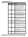
Engineer programming via the keypad .......................................................... 75
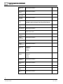
14.1
SYSTEM STATUS.............................................................................................. 75
14.2
OPTIONS ........................................................................................................... 76
14.3
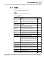
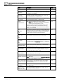
TIMERS .............................................................................................................. 79
14.4
AREAS ............................................................................................................... 81
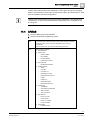
14.5
X-BUS ................................................................................................................. 82
14.5.1
X-Bus addressing ................................................................................ 82
14.5.2
RECONFIGURE.................................................................................. 83
14.5.3
KEYPADS/EXPANDERS/DOOR CONTROLLERS ............................ 84
14.5.3.1 LOCATE .............................................................................................. 84
14.5.3.2 MONITOR ........................................................................................... 84
14.5.3.3 EDIT KEYPADS .................................................................................. 85
14.5.3.4 EDIT EXPANDERS ............................................................................. 88
14.5.3.5 EDIT DOOR CONTROLLERS ............................................................ 88
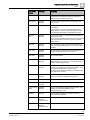
14.6
14.5.4
ADRESSING MODE ........................................................................... 90
14.5.5
XBUS TYPE ........................................................................................ 90
14.5.6
BUS RETRIES .................................................................................... 91
14.5.7
COMMS TIMER .................................................................................. 91
WIRELESS ......................................................................................................... 91
4
Siemens AB
Security Products
A6V10276959
18.11.2011
14.6.1
ADD SENSORS .................................................................................. 92
14.6.2
EDIT SENSORS (ZONE ASSIGNMENT) ........................................... 92
14.6.3
ADD WPA ........................................................................................... 93
14.6.4
EDIT WPA ........................................................................................... 93
14.7
ZONES ............................................................................................................... 94
14.8
DOORS .............................................................................................................. 94
14.8.1
14.9
OUTPUTS .......................................................................................................... 98
14.9.1
14.10
DOORS ............................................................................................... 94
Outputs types and output ports ........................................................... 98
COMMUNICATION .......................................................................................... 101
14.10.1 SERIAL PORTS ................................................................................ 101
14.10.2 ETHERNET PORTS ......................................................................... 102
14.10.3 MODEMS .......................................................................................... 102
14.10.4 CENTRAL STATION......................................................................... 103
14.10.4.1 ADD................................................................................................... 103
14.10.5 REMOTE MAINTENANCE ............................................................... 104
14.11
TEST ................................................................................................................ 104
14.11.1 BELL TEST ....................................................................................... 104
14.11.2 WALK TEST ...................................................................................... 105
14.11.3 ZONE MONITOR .............................................................................. 105
14.11.4 OUTPUT TEST ................................................................................. 106
14.11.5 SOAK TEST ...................................................................................... 106
14.11.6 AUDIBLE OPTIONS ......................................................................... 107
14.11.7 WPA TEST ........................................................................................ 107
14.11.8 SEISMIC TEST ................................................................................. 107
14.12
UTILITIES ......................................................................................................... 108
14.13
ISOLATE .......................................................................................................... 108
14.14
EVENT LOG ..................................................................................................... 109
14.15
CHANGE PIN ................................................................................................... 109
14.16
USERS ............................................................................................................. 109
14.16.1 ADD................................................................................................... 109
14.16.2 EDIT .................................................................................................. 110
14.16.2.1 ACCESS CONTROL......................................................................... 110
14.16.3 DELETE ............................................................................................ 113
14.17
ENGINEER SMS .............................................................................................. 113
14.18
X-10 .................................................................................................................. 114
14.19
SET DATE/TIME .............................................................................................. 114
14.20
INSTALLER TEXT............................................................................................ 115
14.21
DOOR CONTROL ............................................................................................ 115
15
Engineer programming via the browser ...................................................... 116
15.1
Ethernet interface ............................................................................................. 116
15.2
USB interface ................................................................................................... 118
15.3
Logging into the browser .................................................................................. 119
15.4
Panel status ...................................................................................................... 120
15.4.1
Summary ........................................................................................... 120
15.4.2
Zones ................................................................................................ 121
5
Siemens AB
Security Products
A6V10276959
18.11.2011
15.4.3
Doors .................................................................................................123
15.4.4
System alerts .................................................................................... 124
15.4.5
Areas .................................................................................................125
15.4.6
Wireless ............................................................................................ 125
15.4.6.1 Log - Wireless sensor X ....................................................................126
15.4.7
X-Bus ................................................................................................ 127
15.4.8
Logs ..................................................................................................128
15.4.8.1 System Log ....................................................................................... 128
15.4.8.2 Access Log........................................................................................ 128
15.4.8.3 WPA Log ........................................................................................... 129
15.5
15.6
Users ................................................................................................................ 129
15.5.1
Adding / Editing user ......................................................................... 129
15.5.2
User rights ......................................................................................... 131
15.5.3
Access control ................................................................................... 134
15.5.4
Changing engineer PIN .....................................................................136
15.5.5
Changing engineer web PIN ............................................................. 137
15.5.6
Engineer SMS ................................................................................... 138
File Operations .................................................................................................140
15.6.1
Upgrading Firmware.......................................................................... 141
15.6.2
Importing Custom Languages for the Panel .....................................143
15.6.3
Using the Fast Programmer .............................................................. 144
15.6.3.1 Connecting the Fast Programmer to the Controller .......................... 145
15.6.3.2 Installing the Fast Programmer on a PC ........................................... 146
15.6.3.3 Fast Programmer File Operations..................................................... 148
15.7
Changing system settings ................................................................................ 150
15.7.1
Identification ...................................................................................... 150
15.7.2
Standards .......................................................................................... 151
15.7.2.1 Installation type ................................................................................. 153
15.7.2.2 Region ............................................................................................... 153
15.7.2.3 Grade ................................................................................................ 153
15.8
15.7.3
Options .............................................................................................. 154
15.7.4
Timers ............................................................................................... 160
15.7.5
Clock .................................................................................................164
15.7.6
Language .......................................................................................... 164
Configuring zones, doors and areas ................................................................ 165
15.8.1
Editing a zone ................................................................................... 165
15.8.2
Adding / Editing an area ....................................................................166
15.8.2.1 Entry/Exit ........................................................................................... 168
15.8.2.2 Partset Options ................................................................................. 168
15.8.2.3 Linked Areas ..................................................................................... 169
15.8.2.4 Schedule ........................................................................................... 170
15.8.2.5 Setting/Unsetting ............................................................................... 170
15.8.2.6 All Okay ............................................................................................. 173
15.8.2.7 Reporting........................................................................................... 173
15.8.2.8 RF Output.......................................................................................... 175
15.8.2.9 Area Triggers .................................................................................... 176
6
Siemens AB
Security Products
A6V10276959
18.11.2011
15.8.3
Editing a door .................................................................................... 177
15.8.3.1 Door Interlock .................................................................................... 180
15.8.4
15.9
Adding an area group ....................................................................... 181
Configuring controller inputs & outputs ............................................................ 182
15.9.1
Editing an input ................................................................................. 182
15.9.1.1 Input zones: attributes....................................................................... 184
15.9.2
Editing an output ............................................................................... 184
15.9.2.1 Outputs types and output ports ......................................................... 186
15.9.3
15.10
Configuring system latch and auto set outputs ................................. 188
X-BUS............................................................................................................... 190
15.10.1 Keypads ............................................................................................ 190
15.10.1.1 Editing a Standard Keypad ............................................................... 190
15.10.1.2 Editing a Comfort Keypad ................................................................. 192
15.10.2 Expanders ......................................................................................... 195
15.10.2.1 Configuring an Indicator Expander ................................................... 196
15.10.2.2 Configuring a Keyswitch Expander ................................................... 198
15.10.3 Door Controllers ................................................................................ 200
15.10.3.1 Editing a door controller .................................................................... 200
15.10.4 Cable Map ......................................................................................... 202
15.10.5 Settings ............................................................................................. 202
15.11
Wireless ............................................................................................................ 203
15.11.1 Log - Wireless sensor X .................................................................... 204
15.11.2 Changing wireless settings ............................................................... 205
15.11.3 Configuring a WPA ........................................................................... 206
15.11.3.1 Adding a WPA................................................................................... 207
15.11.3.2 Editing a WPA ................................................................................... 209
15.12
Configuring communications ............................................................................ 209
15.12.1 Serial ports ........................................................................................ 209
15.12.1.1 Making a terminal connection to the controller via the serial port .... 211
15.12.1.2 Making a browser connection to the controller via the serial port .... 213
15.12.1.3 Troubleshooting ................................................................................ 214
15.12.2 Modems ............................................................................................ 214
15.12.2.1 PSTN modem ................................................................................... 215
15.12.2.2 GSM modem ..................................................................................... 217
15.12.2.3 SMS test ........................................................................................... 218
15.12.2.4 SMS feature ...................................................................................... 219
15.12.2.5 SMS system options ......................................................................... 219
15.12.2.6 SMS Commands ............................................................................... 219
15.12.3 Ethernet ............................................................................................ 221
15.12.4 Registering to SPC portal ................................................................. 222
15.12.5 Configuring the networking services of the panel ............................. 223
15.12.6 SPC Pro / SPC Safe ......................................................................... 224
15.12.7 Alarm Reporting Centres (ARCs) ..................................................... 226
15.12.7.1 SIA codes .......................................................................................... 226
15.12.7.2 Adding / Editing an ARC ................................................................... 226
15.12.7.3 Editing an ARC filter.......................................................................... 228
7
Siemens AB
Security Products
A6V10276959
18.11.2011
15.12.8 EDP Setup ........................................................................................ 229
15.12.8.1 Adding an EDP Receiver ..................................................................229
15.12.8.2 Editing EDP Receiver Settings ......................................................... 230
15.12.8.3 Editing Event Filter Settings .............................................................. 233
15.12.8.4 Editing EDP settings ......................................................................... 235
15.12.9 Remote Maintenance ........................................................................ 236
15.13
Configuring advanced settings ......................................................................... 236
15.13.1 Calendars .......................................................................................... 236
15.13.1.1 Adding / Editing a calendar ............................................................... 237
15.13.1.2 Auto-Set and Auto-Unset ..................................................................239
15.13.1.3 All other purposes ............................................................................. 239
15.13.2 Triggers ............................................................................................. 239
15.13.3 Mapping Gates .................................................................................. 241
15.13.4 X10 Config - Settings ........................................................................ 242
15.13.5 Updating SPC Licenses ....................................................................244
16
Accessing web server remotely....................................................................245
16.1
PSTN connection.............................................................................................. 245
16.2
GSM connection ............................................................................................... 247
17
Intruder alarm functionality ........................................................................... 250
17.1
Financial mode operation ................................................................................. 250
17.2
Commercial mode operation ............................................................................ 250
17.3
Domestic mode operation ................................................................................ 251
17.4
Full and local alarms......................................................................................... 251
18
System examples and scenarios ..................................................................252
18.1
When to use a common area ........................................................................... 252
19
Audio/Video Verification ................................................................................ 254
19.1
Configuring Video ............................................................................................. 254
19.2
Configuring Verification Zones ......................................................................... 256
19.3
Configuring Verification Settings ......................................................................257
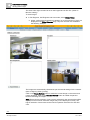
19.4
Viewing Video Images ...................................................................................... 257
19.5
Configuring Video ............................................................................................. 259
20
Seismic Sensors ............................................................................................. 262
20.1
Seismic Sensor Testing .................................................................................... 264
20.1.1
Manual and Automatic Test Process ................................................ 264
20.1.2
Automatically Testing Sensors.......................................................... 265
20.1.3
Manually Testing Sensors .................................................................266
21
Appendix ......................................................................................................... 268
21.1
Network cable connections .............................................................................. 268
21.2
Controller status LEDs...................................................................................... 268
21.3
Powering expanders from the auxiliary power terminals..................................269
21.4
Calculating the battery power requirements ..................................................... 270
21.5
Domestic, Commercial and Financial mode default settings ........................... 272
21.6
Wiring of the X10 interface ............................................................................... 273
21.7
SIA Codes ........................................................................................................ 273
21.8
CID Codes ........................................................................................................ 278
8
Siemens AB
Security Products
A6V10276959
18.11.2011
21.9
Overview of keypad types ................................................................................ 279
21.10
User PIN combinations..................................................................................... 280
21.11
Duress PINs ..................................................................................................... 281
21.12
Automatic inhibits ............................................................................................. 281
21.12.1 Zones ................................................................................................ 281
21.12.2 Access PINs ...................................................................................... 281
21.12.3 Engineer Access ............................................................................... 282
21.12.4 Keypad User Logoff .......................................................................... 282
21.13
Wiring of mains cable to the controller ............................................................. 282
21.14
Maintenance controller ..................................................................................... 282
21.15
Maintenance Smart PSU .................................................................................. 283
21.16
Zone types ........................................................................................................ 284
21.17
Zone attributes ................................................................................................. 286
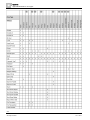
21.18
Applicable attributes to zone types .................................................................. 289
21.19
ATS levels and attenuation specifications........................................................ 291
21.20
Compliance with EN50131-1 Approvals........................................................... 291
21.21
Compliance with INCERT Approvals ............................................................... 293
9
Siemens AB
Security Products
A6V10276959
18.11.2011
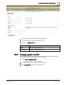
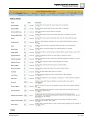
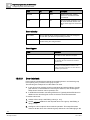
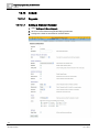
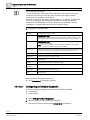
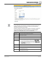
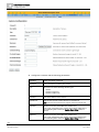
1
Meaning of symbols
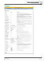
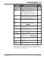
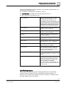
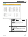
1 Meaning of symbols
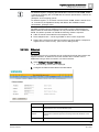
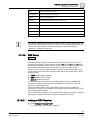
There are several symbols in the document:
Symbol
Description
Not available for SPC42xx, SPC43xx.
Only available for SPC controller with IP interface
(SPC43xx/SPC53xx/SPC63xx).
Not available for installation type Domestic.
!
!
Only available in unrestricted mode.
Find further information about Security Grade, Region or Mode in text.
See Appendix for further information.
10
Siemens AB
Security Products
A6V10276959
18.11.2011
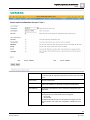
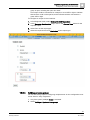
Security
Target group
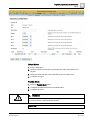
2
2 Security
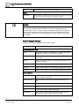
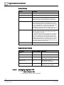
2.1
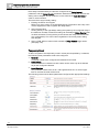
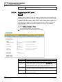
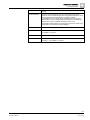
Target group
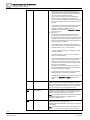
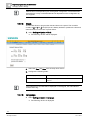
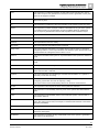
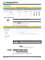
The instructions in this documentation are directed at the following target group:
Target readers
2.2
Qualification
Activity
Condition of the
equipment
Installation personnel Technical training for Assembles and
building or electrical installs the hardware
installations.
components on site.
Individual
components that
need to be
assembled and
installed.
Operational startup
personnel
New, readily
assembled and
installed device or
modified device.
Has appropriate
technical training with
regard to the tasks
and the products,
devices or systems
to be put in service.
Puts the device or
system which is
readily assembled
and installed on site
into service.
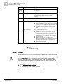
General safety instructions
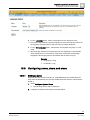
WARNING
Before starting to install and work with this device, please read the Safety
Instructions. This device shall only be connected to power supplies compliant to
EN60950-1, chapter 2.5 ("limited power source").
2.2.1
General information
Keep this document for later reference.
Always pass this document on together with the product.
Please also take into account any additional country-specific, local safety
standards or regulations concerning project planning, operation and disposal of
the product.
Liability claim
Do not connect the device to the 230 V supply network if it is damaged or any
parts are missing.
Do not make any changes or modifications to the device unless they are
expressly mentioned in this manual and have been approved by the
manufacturer.
Use only spare parts and accessories that have been approved by the
manufacturer.
11
Siemens AB
Security Products
A6V10276959
18.11.2011
2
Security
General safety instructions
2.2.2
Transport
Unit damage during transport
2.2.3
Keep the packaging material for future transportation.
Do not expose the device to mechanical vibrations or shocks.
Setup
Radio interference with other devices in the environment / EMS
When handling modules that are susceptible to electrostatic discharge, please
observe the ESD guidelines.
Damage due to unsuitable mounting location
The environmental conditions recommended by the manufacturer must be
observed.
See Technical Data.
Do not operate the device close to sources of powerful electromagnetic
radiation.
Danger of electrical shock due to incorrect connection
Connect the device only to power sources with the specified voltage. Voltage
supply requirements can be found on the rating label of the device.
Ensure that the device is permanently connected to the electricity supply; a
readily accessible disconnect device must be provided.
Ensure that the circuit that the device is connected to is protected with a 16 A
(max.) fuse. Do not connect any devices from other systems to this fuse.
This device is designed to work with TN power systems. Do not connect the
device to any other power systems.
Electrical grounding must meet the customary local safety standards and
regulations.
Primary supply cables and secondary cables should be routed such that they
do not run in parallel or cross over or touch one anther inside the housing.
Telephone cables should be fed into the unit separately from other cables.
Risk of cable damage due to stress
2.2.4
Ensure that all outgoing cables and wires are sufficiently strain-relieved.
Operation
Dangerous situation due to false alarm
Make sure to notify all relevant parties and authorities providing assistance
before testing the system.
To avoid panic, always inform all those present before testing any alarm
devices.
12
Siemens AB
Security Products
A6V10276959
18.11.2011
Security
Meaning of written warning notices
2
Danger of explosion or burn hazard if the battery is improperly
installed
2.2.5
When inserting new batteries make sure the battery poles are correctly
positioned.
Use only batteries that have been approved by the manufacturer (type: sealed
cell valve-regulated).
Do not shorten the battery pins.
Do not expose the battery to fire or high temperatures.
Do not disassemble the battery.
Discard used batteries according to local regulations.
Make sure to insert the battery correctly and to fasten the battery strap or clip
provided for this purpose.
Service and maintenance
Danger of electrical shock during maintenance
Maintenance work must only be carried out by trained specialists.
Always disconnect the power cable and other cables from the main power
supply before performing maintenance.
Danger of electrical shock while cleaning the device
2.3
2.4
Do not use liquid cleaners or sprays that contain alcohol, spirit or ammonia.
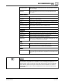
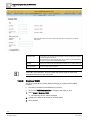
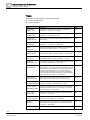
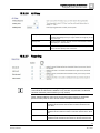
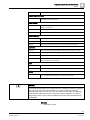
Meaning of written warning notices
Signal Word
Type of Risk
DANGER
Danger of death or severe bodily harm.
WARNING
Possible danger of death or severe bodily
harm.
CAUTION
Danger of minor bodily injury or property
damage
IMPORTANT
Danger of malfunctions
Meaning of hazard symbols
WARNING
Warning of hazard area
13
Siemens AB
Security Products
A6V10276959
18.11.2011
2
Security
Meaning of hazard symbols
WARNING
Warning of dangerous electrical voltage
14
Siemens AB
Security Products
A6V10276959
18.11.2011
Directives and standards
EU directives
3
3 Directives and standards
3.1
EU directives
This product complies with the requirements of the European Directives
2004/108/EC “Directive of Electromagnetic Compatibility” and 2006/95/EC “Low
Voltage Directive”. The EU declaration of conformity is available to the responsible
agencies at:
Siemens AB
Building Technologies Division
International Headquarters
Fire Safety & Security Products
Postal Address
P.O. Box 1275
SE-171 24 Solna, Sweden
European Directive 2004/108/EC „Electromagnetic Compatibility”
Compliance with the European Directive 2004/108/EC has been proven by testing
according to the following standards:
emc emission
EN 55022 Class B
emc immunity
EN 50130-4
European Directive 2006/95/EC „Low-Voltage Directive”
Compliance with the European Directive 2006/95/EC has been proven by testing
according to the following standard:
Safety
3.1.1
EN 60950-1
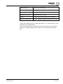
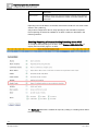
Conformity to EN50131 Standard
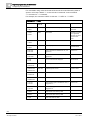
Specific information in relation to EN 50131 requirements can be found in the
following sections in this document.
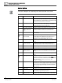
EN50131 Requirement
SPC Installation & Configuration Manual
Operating temperature and humidity range
Technical data SPC4000 [➙ 19]
Technical data SPC5000 [➙ 21]
Technical data SPC6000 [➙ 23]
Weights and dimensions
Technical data SPC4000 [➙ 19]
Technical data SPC5000 [➙ 21]
Technical data SPC6000 [➙ 23]
Fixing details
Mounting system equipment [➙ 27]
Installation, commissioning and
maintenance instructions, including terminal
Mounting system equipment [➙ 27]
15
Siemens AB
Security Products
A6V10276959
18.11.2011
3
Directives and standards
EU directives
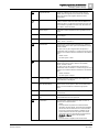
EN50131 Requirement
SPC Installation & Configuration Manual
identifications
Controller hardware [➙ 36]
Type of interconnections (refer to 8.8);
Technical data SPC4000 [➙ 19]
Technical data SPC5000 [➙ 21]
Technical data SPC6000 [➙ 23]
Wiring the X-Bus Interface [➙ 40]
Details of methods of setting and unsetting
User programming via the keypad
possible (see 11.7.1 to 11.7.3 and Tables 23 Areas – Setting/Unsetting [➙ 170]
to 26);
Configuring a keyswitch expander [➙ 198]
Configuring a wireless fob [➙ 72]
Triggers [➙ 239]
Serviceable parts
Technical data SPC4000 [➙ 19]
Technical data SPC5000 [➙ 21]
Technical data SPC6000 [➙ 23]
Power supply requirement if no integrated
PS
See installation instructions for SPCP33x
and SPCP43x Expander PSUs.
Where PS is integrated, the information
required by EN 50131-6:2008, Clause 6
Technical data SPC4000 [➙ 19]
Technical data SPC5000 [➙ 21]
Technical data SPC6000 [➙ 23]
Maximum number of each type of ACE and
expansion device.
Wiring the X-Bus Interface [➙ 40]
Technical data SPC4000 [➙ 19]
Technical data SPC5000 [➙ 21]
Technical data SPC6000 [➙ 23]
Current consumption of the CIE and each
See relevant installation instructions.
type of ACE and expansion device, with and
without an alarm condition.
Maximum current rating of each electrical
output
Technical data SPC4000 [➙ 19]
Technical data SPC5000 [➙ 21]
Technical data SPC6000 [➙ 23]
Programmable functions provided
Engineer programming via the keypad [➙
75]
Engineer programming via the browser [➙
116]
How indications are made inaccessible to
level 1 users when level 2, 3 or 4 user is no
longer accessing the information (see 8.5.1)
Keypad user interface [➙ 57]
Standard keypad settings [➙ 85]
Comfort keypad settings [➙ 86]
Configuring an Indicator Expander [➙ 196]
Masking/reduction of range
System Options [➙ 156]
signals/messages processed as “fault” or
Wiring the zone inputs [➙ 51]
“masking” events (see 8.4.1, 8.5.1 and Table
SIA Codes [➙ 273]
11);
PIR masking is always reported as a zone
masked event (SIA - ZM). Additionally, antimask can cause an alarm, tamper, trouble
or no additional action depending on
configuration
Current defaults of PIR addition effect:
Ireland
16
Siemens AB
Security Products
A6V10276959
18.11.2011
Directives and standards
EU directives
EN50131 Requirement
3
SPC Installation & Configuration Manual
Unset - None
Set - Alarm
UK, Europe, Sweden, Swiss, Belgium
Unset - Tamper
Set - Alarm
Prioritization of signal and message
processing and indications (see 8.4.1.2,
8.5.3);
Standard keypad display [➙ 59]
Comfort keypad display [➙ 62]
Minimum number of variations of PIN codes, User PIN combinations [➙ 280]
logical keys, biometric keys and/or
mechanical keys for each user (see 8.3);
Method of time-limiting internal WD for level
3 access without level 2 authorization (see
8.3.1);
Not supported - Engineer cannot access
system without permission.
Number and details of disallowed PIN codes Automatic inhibits [➙ 281]
(see 8.3.2.2.1);
Details of any biometric authorization
methods used (see 8.3.2.2.3);
Not applicable
Method used to determine the number of
combinations of PIN codes, logical keys,
biometric keys and/or mechanical keys (see
11.6);
User PIN combinations [➙ 280]
Number of invalid code entries before user
interface is disabled (see 8.3.2.4);
Access PINs [➙ 281]
Details of means for temporary authorization User Menus – Grant Access
for user access (see 8.3.2);
if automatic setting at pre-determined times Areas – Setting/Unsetting [➙ 170]
provided, details of pre-setting indication and
any automatic over-ride of prevention of set
(see 8.3.3, 8.3.3.1);
Details of conditions provided for the set
state (see 8.3.3.4);
Setting and unsetting the system
Standard keypad configuration [➙ 85]
Comfort keypad configuration [➙ 86]
Outputs [➙ 185]
Zone types [➙ 284]
Notification of output signals or messages
provided (see 8.6);
Outputs [➙ 185]
Areas – setting/unsetting [➙ 170]
User rights [➙ 131]
Other output configurations to interface with
I&HAS components (see 8.2);
Outputs [➙ 185]
Zone types [➙ 284]
Test [➙ 104]
Keypad user interface [➙ 57]
Criteria for automatic removal of “soak test”
attribute (see 8.3.9);
Timers [➙ 160]
Number of events resulting in automatic
inhibit
Automatic Inhibits [➙ 281]
17
Siemens AB
Security Products
A6V10276959
18.11.2011
3
Directives and standards
EU directives
EN50131 Requirement
SPC Installation & Configuration Manual
If ACE is Type A or Type B (see 8.7) and
whether portable or moveable (see 11.14);
All devices are hardwired and powered by
system PSUs. Refer to relevant technical
data on PSUs.
Component data for non-volatile memory
components (see Table 30, step 6);
See user documentation for SPCK420/421
and SPCK620/623 keypads.
Life of memory support battery (see 8.10.1);
N/A. Stored in non-volatile memory.
Optional functions provided (see 4.1);
Engineer programming via the keypad
Engineer programming via the browser [➙
116]
Additional functions provided (see 4.2,
8.1.8);
Grade - Unrestricted [➙ 153]
Policies – System options [➙ 156]
Access levels required to access such
additional functions provided;
User configuration (keypad) [➙ 110]
User configuration (browser) [➙ 129]
Details of any programmable facility that
would render an I&HAS non-compliant with
EN 50131-1:2006, 8.3.13 or compliant at a
lower security grade, with instruction on
consequent removal of compliance labeling
(see 4.2 and 8.3.10).
Grade - Unrestricted [➙ 153]
Policies – System options [➙ 156]
EN50131 Compliance [➙ 291]
18
Siemens AB
Security Products
A6V10276959
18.11.2011
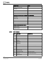
Technical Data
SPC4000
4
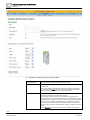
4 Technical Data
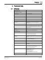
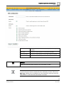
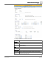
4.1
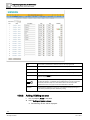
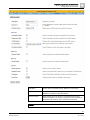
SPC4000
Programmable areas
4
Max. number of user codes
32
Remote controls
Up to 32 (1 per user)
Wireless Panic Alarm
Up to 32
Event memory
1'000 intrusion events, 1'000 access events
Number of on-board zones
8
Max. number of hardwired zones
32
Max. number of wireless zones
32 (take away wired zones)
EOL resistor
Dual 4k7 (default), other resistor combinations
configurable
Number of on-board relays
1 strobe (30 VDC / 1 A resistive switching current)
Number of on-board open coll.
2 internal / external bell, 3 freely programmable (each
max. 400 mA resistive switching current, supplied via
auxiliary output)
Firmware
V3.x
Door capacity
Max. 4 entry doors or 2 entry/exit doors
Number of card reader
Max. 4
Radio module
SPC4221: integrated SiWay RF receiver (868 MHz)
SPC4320.220: Optional (SPCW111),
SPC4320.320: Optional (SPCW110)
Verification
4 verification zones with max. 4 IP-cameras and 4 audio
devices.
Video
Up to 16 pre / 16 post event images (by JPEG resolution
320 x 240, max. 1 frame / sec.)
Audio
Up to 60 sec. pre / 60 sec. post audio recording
Field bus 1)
X-BUS on RS-485 (307 kb/s)
Number of field devices 2)
Max. 11 (4 keypads, 4 door-expanders, 5 input/output
expanders)
Connectable field devices
Keypads: SPCK42x, SPCK62x
Door expanders: SPCA210, SPCP43x
Expanders with I/O: SPCE65x, SPCE45x, SPCP33x,
SPCE110, SPCE120, SPCV32x
Interfaces
1 X-BUS (1 spur),
1 RS232 (to X-10 controller),
1 USB (PC connection),
1 SPC Fast Programmer,
SPC43xx: Additionally 1 Ethernet (RJ45)
Tamper contact
Front spring tamper, 2 auxiliary tamper contact inputs
19
Siemens AB
Security Products
A6V10276959
18.11.2011
4
Technical Data
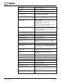
SPC4000
Power supply
Type A (per EN50131-1)
Mains voltage
230 VAC, + 10%/ -15%, 50 Hz
Mains fuse
250 mA T (replaceable part on mains terminal block)
Power consumption
SPC42xx: Max. 160 mA at 230 VAC
SPC43xx: Max. 200 mA at 230 VAC
Operating current
SPC42xx Controller: Max. 160 mA at 12 VDC
SPC43xx Controller: Max. 200 mA at 12 VDC
Quiescent current
SPC42xx Controller:
Max. 140 mA at 12 VDC (165 mA with PSTN, 270 mA
with GSM, 295 mA with PSTN & GSM)
SPC43xx Controller:
Max. 170 mA at 12 VDC (195 mA with PSTN, 300 mA
with GSM, 325 mA with PSTN & GSM)
Output voltage
11-14 VDC in normal conditions (mains powered and
fully charged battery), min. 9.5 VDC when powered by
secondary device (before system shut down to battery
deep discharge protection)
Low voltage trigger
7.5 VDC
Overvoltage protection
15.7 VDC
Peak to Peak ripple
Max. 5 % of output voltage
Auxiliary power (nominal)
Max. 750 mA at 12 VDC
Battery type
SPC422x/4320: YUASA NP7-12FR (7 Ah), Battery not
supplied
Battery charger
SPC422x/4320: Max. 72h to 80% of battery capacity
Battery protection
Current limited to 1 A (fuse protected), deep discharge
protection at 10.5 VDC +/- 3 % (fault at deep discharge
voltage + 0.5 VDC)
Software update
On-site and remote upgrade for controller and
peripherals
Calibration
No calibration checks required (calibrated at
manufacturing)
Servicable parts
No serviceable parts
Operating temperature
0 ~ +40 °C
Relative humidity
Max. 90 % (non condensing)
Colour
RAL 9003 (signal white)
Weight
SPC422x/4320: 4.500 kg
Dimensions (W x H x D)
SPC422x/4320: 264 x 357 x 81 mm
Housing
SPC4320.320: Small metal housing (1.2 mm mild steel)
SPC422x.220: Small housing with metal base (1.2 mm
mild steel) and plastic lid
Housing can contain up to
SPC422x/4320: 1 additional expander (size 150 mm x 82
mm)
20
Siemens AB
Security Products
A6V10276959
18.11.2011
Technical Data
SPC5000
4
1) Max. 400 m between devices / cable types IYSTY 2 x 2 x Ø 0.6 mm (min.), UTP
cat5 (solid core) or Belden 9829.
2) More I/O expanders can be addressed instead of a keypad or door expander,
but number of programmable inputs / outputs cannot exceed specified system
limits.
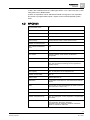
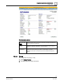
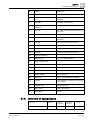
4.2
SPC5000
Programmable areas
16
Max. number of user codes
256
Remote controls
Up to 256 (1 per user)
Wireless Panic Alarm
Up to 127
Event memory
10'000 intrusion events, 10'000 access events
Number of on-board zones
8
Max. number of hardwired
zones
128
Max. number of wireless zones 120 (take away wired zones)
EOL resistor
Dual 4k7 (default), other resistor combinations
configurable
Number of on-board relays
1 strobe (30 VDC / 1 A resistive switching current)
Number of on-board open coll.
2 internal / external bell, 3 freely programmable (each
max. 400 mA resistive switching current, supplied via
auxiliary output)
Firmware
V3.x
Door capacity
Max. 16 entry doors or 16 entry/exit doors
Number of card reader
Max. 32
Radio module
Optional (SPCW110)
Verification
8 verification zones with max. 4 IP-cameras and 8 audio
devices.
Video
Up to 16 pre / 16 post event images (by JPEG resolution
320 x 240, max. 1 frame / sec.)
Audio
Up to 60 sec. pre / 60 sec. post audio recording
Field bus 1)
X-BUS on RS-485 (307 kb/s)
Number of field devices 2)
Max. 48 (16 keypads, 16 door-expanders, 16 input/output
expanders)
Connectable field devices
Keypads: SPCK42x, SPCK62x
Door expanders: SPCA210, SPCP43x
Expanders with I/O: SPCE65x, SPCE45x, SPCP33x,
SPCE110, SPCE120, SPCV32x
21
Siemens AB
Security Products
A6V10276959
18.11.2011
4
Technical Data
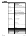
SPC5000
Interfaces
2 X-BUS (2 spurs or 1 loop),
2 RS232 (to X-10 controller or external communication),
1 USB (PC connection),
1 SPC Fast Programmer,
SPC53xx: Additionally 1 Ethernet (RJ45)
Tamper contact
Front spring tamper, 2 auxiliary tamper contact inputs
Power supply
Type A (per EN50131-1)
Mains voltage
230 VAC, + 10%/ -15%, 50 Hz
Mains fuse
250 mA T (replaceable part on mains terminal block)
Power consumption
SPC53xx: Max. 200 mA at 230 VAC
Operating current
SPC53xx Controller: Max. 200 mA at 12 VDC
Quiescent current
SPC53xx Controller: Max. 170 mA at 12 VDC (195 mA
with PSTN, 300 mA with GSM, 325 mA with PSTN &
GSM)
Output voltage
11-14 VDC in normal conditions (mains powered and fully
charged battery), min. 9.5 VDC when powered by
secondary device (before system shut down to battery
deep discharge protection)
Low voltage trigger
7.5 VDC
Overvoltage protection
15.7 VDC
Peak to Peak ripple
Max. 5 % of output voltage
Auxiliary power (nominal)
Max. 750 mA at 12 VDC
Battery type
SPC5320: YUASA NP7-12FR (7 Ah),
SPC5330: YUASA NP17-12FR (17 Ah), Battery not
supplied
Battery charger
SPC5320: Max. 72h,
SPC5330: Max. 24h
to 80% of battery capacity
Battery protection
Current limited to 1 A (fuse protected), deep discharge
protection at 10.5 VDC +/- 3 % (fault at deep discharge
voltage + 0.5 VDC)
Software update
On-site and remote upgrade for controller and peripherals
Calibration
No calibration checks required (calibrated at
manufacturing)
Servicable parts
No serviceable parts
Operating temperature
0 ~ +40 °C
Relative humidity
Max. 90 % (non condensing)
Colour
RAL 9003 (signal white)
Weight
SPC5320: 4.500 kg
SPC5330: 6.100 kg
22
Siemens AB
Security Products
A6V10276959
18.11.2011
Technical Data
SPC6000
4
Dimensions (W x H x D)
SPC5320: 264 x 357 x 81 mm
SPC5330: 326 x 415 x 114 mm
Housing
SPC5320: Small metal housing SPC5330: Hinged metal
housing,
(1.2 mm mild steel)
Housing can contain up to
SPC5320: 1 additional expander,
SPC5330: 4 additional expanders (size 150 mm x 82 mm)
1) Max. 400 m between devices / cable types IYSTY 2 x 2 x Ø 0.6 mm (min.), UTP
cat5 (solid core) or Belden 9829.
2) More I/O expanders can be addressed instead of a keypad or door expander,
but number of programmable inputs / outputs cannot exceed specified system
limits.
4.3
SPC6000
Programmable areas
60
Max. number of user codes
512
Remote controls
Up to 512 (1 per user)
Wireless Panic Alarm
Up to 120
Event memory
10'000 intrusion events, 10'000 access events
Number of on-board zones
8
Max. number of hardwired
zones
512
Max. number of wireless
zones
120 (take away wired zones)
EOL resistor
Dual 4k7 (default), other resistor combinations configurable
Number of on-board relays
1 strobe (30 VDC / 1 A resistive switching current)
Number of on-board open
coll.
2 internal / external bell, 3 freely programmable (each max.
400 mA resistive switching current, supplied via auxiliary
output)
Firmware
V3.x
Door capacity
Max. 64 entry doors or 32 entry/exit doors
Number of card reader
Max. 64
Radio module
Optional (SPCW110)
Verification
16 verification zones with max. 4 IP-cameras and 16 audio
devices.
Video
Up to 16 pre / 16 post event images (by JPEG resolution
320 x 240, max. 1 frame / sec.)
23
Siemens AB
Security Products
A6V10276959
18.11.2011
4
Technical Data
SPC6000
Audio
Up to 60 sec. pre / 60 sec. post audio recording
Field bus 1)
X-BUS on RS-485 (307 kb/s)
Number of field devices 2)
Max. 128 (32 keypads, 32 door-expanders, 64 input/output
expanders)
Connectable field devices
Keypads: SPCK42x, SPCK62x
Door expanders: SPCA210, SPCP43x
Expanders with I/O: SPCE65x, SPCE45x, SPCP33x,
SPCE110, SPCE120, SPCV32x
Interfaces
2 X-BUS (2 spurs or 1 loop),
2 RS232 (to X-10 controller or external communication),
1 USB (PC connection),
1 SPC Fast Programmer,
SPC63xx: Additionally 1 Ethernet (RJ45)
Tamper contact
Front spring tamper, 2 auxiliary tamper contact inputs
Power supply
Type A (per EN50131-1)
Mains voltage
230 VAC, + 10%/ -15%, 50 Hz
Mains fuse
250 mA T (replaceable part on mains terminal block)
Power consumption
SPC63xx: Max. 200 mA at 230 VAC
Operating current
SPC63xx Controller: Max. 200 mA at 12 VDC
Quiescent current
SPC63xx Controller: Max. 170 mA at 12 VDC (195 mA with
PSTN, 300 mA with GSM, 325 mA with PSTN & GSM)
Output voltage
11-14 VDC in normal conditions (mains powered and fully
charged battery), min. 9.5 VDC when powered by
secondary device (before system shut down to battery deep
discharge protection)
Low voltage trigger
7.5 VDC
Overvoltage protection
15.7 VDC
Peak to Peak ripple
Max. 5 % of output voltage
Auxiliary power (nominal)
Max. 750 mA at 12 VDC
Battery type
SPC6330: YUASA NP17-12FR (17 Ah), Battery not
supplied
Battery charger
SPC6330: Max. 24h to 80% of battery capacity
Battery protection
Current limited to 1 A (fuse protected), deep discharge
protection at 10.5 VDC +/- 3 % (fault at deep discharge
voltage + 0.5 VDC)
Software update
On-site and remote upgrade for controller and peripherals
Calibration
No calibration checks required (calibrated at manufacturing)
Servicable parts
No serviceable parts
Operating temperature
0 ~ +40 °C
24
Siemens AB
Security Products
A6V10276959
18.11.2011
Technical Data
SPC6000
4
Relative humidity
Max. 90 % (non condensing)
Colour
RAL 9003 (signal white)
Weight
SPC6330: 6.100 kg
Dimensions (W x H x D)
SPC6330: 326 x 415 x 114 mm
Housing
SPC6330: Hinged metal housing (1.2 mm mild steel)
Housing can contain up to
SPC6330: 4 additional expanders (size 150 mm x 82 mm)
1) Max. 400 m between devices / cable types IYSTY 2 x 2 x Ø 0.6 mm (min.), UTP
cat5 (solid core) or Belden 9829.
2) More I/O expanders can be addressed instead of a keypad or door expander,
but number of programmable inputs / outputs cannot exceed specified system
limits.
25
Siemens AB
Security Products
A6V10276959
18.11.2011
Introduction
5
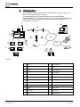
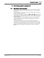
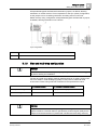
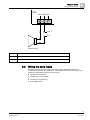
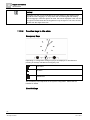
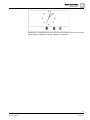
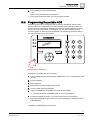
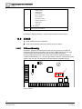
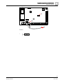
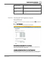
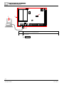
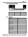
5 Introduction
The SPC series controller is a true hybrid controller with 8 on-board wired zones
that communicate with intruder devices.
The flexible design of the controller allows the functional components
(PSTN/GSM/RF) to be mixed and matched, improving the capability of the system.
Using this approach, an installer can ensure that an efficient installation with
minimal wiring is achieved.
5
6
7
4
8
9
20
16
17
1
2
22
19
3
10
11
18
13
12
21
23
24
14
15
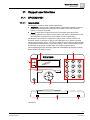
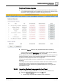
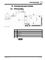
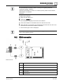
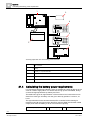
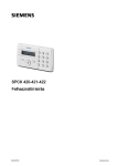
Overview
1 PSTN
13
Wireless expander
2 GSM
14
PSU
3 Ethernet
15
Loop configuration
4 RF
16
PSTN network
5 AC mains
17
GSM network
6 Battery 12 V
18
Broadband router
7 Wireless receiver (24)
19
Network
8 Wired outputs (6)
20
Central
9 Wired inputs (8)
21
LAN/WLAN
10 Keypads
22
Service desk
11 IO expander
23
Remote user
12 Output
24
Mobile interfaces
26
Siemens AB
Security Products
A6V10276959
18.11.2011
Mounting system equipment
Mounting a G2 enclosure
6
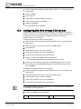
6 Mounting system equipment
6.1
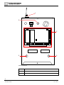
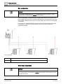
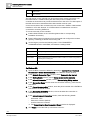
Mounting a G2 enclosure
The SPC G2 enclosure is supplied with a metallic cover. The cover is attached to
the base of the enclosure by 2 securing screws located on the top and bottom of
the front cover.
To open the enclosure, remove both screws with the appropriate screwdriver and
lift the cover directly from the base.
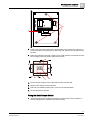
The G2 enclosure contains the controller PCB (Printed Circuit Board) mounted on
4 support pillars. An optional input/output module can be mounted directly beneath
the controller PCB. A battery with capacity of 7 Ah max. can be accommodated
below the controller.
An optional external antenna must be fitted to enclosures with metallic lid if the
wireless functionality is required. If an antenna is fitted to the unit, it must be
enabled in the firmware.
The SPC G2 enclosure provides 3 screw holes for wall mounting the unit.
To wall mount the enclosure, remove the cover and locate the initial fixing screw
hole at the top of the cabinet. Mark the position of this screw hole on the desired
location on the wall and drill the initial screw hole. Screw the unit to the wall and
mark the position of the bottom 2 screw hole positions with the unit vertically
aligned.
27
Siemens AB
Security Products
A6V10276959
18.11.2011
6
Mounting system equipment
Mounting a G2 enclosure
1
3
2
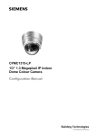
3
3
Standard enclosure
1 Wireless antenna
2 SPC controller
3 Wall mounting screw holes
28
Siemens AB
Security Products
A6V10276959
18.11.2011
Mounting system equipment
Mounting a G3 enclosure
6.2
6
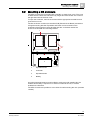
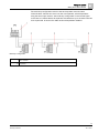
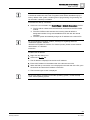
Mounting a G3 enclosure
The SPC G3 enclosure is supplied with a metallic or plastic front cover. The cover
is attached to the base of the enclosure by hinges and secured with one screw on
the right hand side of the front cover.
To open the enclosure, remove the screws with the appropriate screwdriver and
open the front cover.
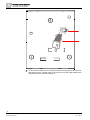
The G3 enclosure contains the controller PCB (Printed Circuit Board) mounted on
a hinged mounting bracket. Expanders and PSUs can be mounted on the
underside of the hinged mounting bracket and also on the back wall of the
enclosure underneath the mounting bracket.
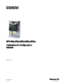
1
3
2
4
1
Expanders/PSU
2
Controller
3
Expanders/PSU
4
Battery
An optional external antenna must be fitted to enclosures with metallic lid if the
wireless functionality is required. If an antenna is fitted to the unit, it must be
enabled in the firmware.
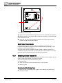
The SPC G3 enclosure provides 3 screw holes for wall mounting the unit. (see item
1 below)
29
Siemens AB
Security Products
A6V10276959
18.11.2011
6
Mounting system equipment
Mounting a G3 enclosure
To wall mount the enclosure:
1. Open the cover and locate the initial fixing screw hole at the top of the cabinet.
2. Mark the position of this screw hole on the desired location on the wall and drill
the initial screw hole.
3. Screw the unit to the wall and mark the position of the bottom 2 screw hole
positions with the unit vertically aligned.
Back Tamper Requirements
A back tamper switch on a Grade 3 panel is a mandatory requirement for
compliance with EN50131 approval. The back tamper switch is required for SSF
Larmklass 2 and EN Alarm Grade 3.
The back tamper switch is delivered with SPC panels in Grade 3 cabinets or is
available as an optional extra with a mounting kit (SPCY130). EN50131 G3 panels
(SPCxx3x.x20) are supplied with a back tamper kit as standard.
6.2.1
Mounting a Back Tamper Kit
The SPC back tamper kit provides SPC control panels and power supplies with the
option of having back tamper as well as front tamper.
The back tamper kit comprises the following parts:
Tamper switch
Leads for connecting the back tamper switch to the controller
Wall fixing plate
Mounting the Wall Fixing Plate
1. Mount the SPC in the appropriate position on the wall using all three fixings
(see item 1 below).
30
Siemens AB
Security Products
A6V10276959
18.11.2011
Mounting system equipment
Mounting a G3 enclosure
6
+ –
1
2
2. Draw a line around the inside of the back tamper cut out (See item 2 above) to
provide a guide for the wall plate on the fixing wall. Remove the enclosure from
the wall.
3. Place the wall plate (See item 1 below) on the wall centering it precisely around
the rectangle previously drawn (See item 2 below).
B
A
A
B
1
2
4. Ensure all four flanges on the wall plate are flush with the wall.
5. Mark the four fixings on the wall plate.
6. Drill and use suitable screws (max. 4 mm) for the wall substrate.
7. Fit the wall plate to the wall.
Fitting the Back Tamper Switch
1. Insert the tamper switch (See item 2 below) into the back of the enclosure so
that the plunger faces outwards (See item 1 below).
31
Siemens AB
Security Products
A6V10276959
18.11.2011
6
Mounting system equipment
Mounting a G3 enclosure
2. Fit the enclosure back onto the wall using the three fixings previously removed
(See item 2 below). Visually check to ensure there is a flush finish between the
wall plate and the enclosure metalwork.
32
Siemens AB
Security Products
A6V10276959
18.11.2011
Mounting system equipment
Mounting a G3 enclosure
6
3
4
1
2
1
Enclosure
3
Wall Fixing Plate
2
Wall
4
Tamper Switch
WARNING
If the wall fixing plate is not accurately aligned then the enclosure will not sit
properly on its fixings.
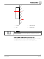
Wiring the Back Tamper Switch to the Control Panel
All control panels have spare inputs configured as tamper inputs that are designed
for wiring the tamper switch and do not require any programming.
This tamper switch will be referred to as ‘Aux Tamper 1’ by the system.
33
Siemens AB
Security Products
A6V10276959
18.11.2011
6
Mounting system equipment
Battery installation
+–
CN23
T1 C T2
NO
NC
COM
1. Connect NO on the tamper switch to T1 on the controller.
2. Connect COM on the tamper switch to C on the controller. Ensure the T2
jumper is not removed.
3. When the tamper switch is wired, the controller can be commissioned in the
normal manner.
6.3
Battery installation
For EN50131 compliance the battery needs to be retained within the housing to
stop movement. This is achieved by bending out the flaps in the rear of the Hinged
Enclosure so that the battery is retained.
If a 7 Ah battery is used then the battery is biased to the left of the cabinet and
bottom flap is bent to meet the battery.
If a 17 Ah battery is used then the battery is biased to the right of the cabinet and
middle flap is bent to meet the battery.
34
Siemens AB
Security Products
A6V10276959
18.11.2011
Mounting system equipment
Mounting a keypad
6
The battery flaps should be bent carefully as not to damage the battery. If any
signs of a damaged battery exist or any leakage of the electrolyte then the battery
should be discarded as per the current regulations and a new battery fitted.
6.4
Mounting a keypad
Please refer to corresponding installation instruction.
6.5
Mounting an expander
Please refer to corresponding installation instruction.
35
Siemens AB
Security Products
A6V10276959
18.11.2011
7
Controller hardware
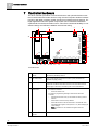
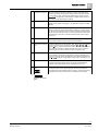
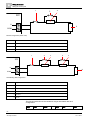
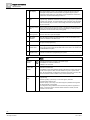
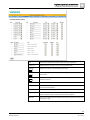
7 Controller hardware
The SPC controller provides 8 on-board wired zones and optional wireless zones
that communicate with intruder devices using the new European standard wireless
frequency 868 MHz, providing greater security from interference and jamming. For
larger applications the SPC system components can be mixed and matched to
expand both the wired and wireless zones. This offers unmatched flexibility in cost
effective design and efficient installation with minimal wiring.
1
2
3
4
21
20
19
7
8
9
TX
RX
GND
T1
C
T2
I1
C
I2
I3
C
I4
I5
C
I6
I7
C
I8
19
5
6
0V
12 V
SH
2B
2A
1B
1A
12 V
OP6
OP5
OP4
NC
COM
NO
BHO
TR
IN –
IN +
EXP –
EXP +
+–
18
17
16
15 14
13
12
10
11
Controller board
1 Optional wireless
module
The controller PCB can be factory fitted with a wireless module for use
with wireless (868 MHz) sensors.
2 SPC status LEDs
These 7 LEDs display the status of various system parameters as
described on page [➙ 268].
3 AC power input
The mains AC input voltage is applied to this 2-pin connection via a
transformer contained in the SPC enclosure. The earth lead from the
mains supply is wired to a connection point on the metal cabinet.
4 Reset button
To reset the controller:
–
5 Earth connection
terminal
Press this switch once.
To reset the programming settings to default and reboot the
controller:
–
Hold down the button until you are asked if a factory reset is
desired.
–
Select YES to reset to factory defaults.
–
Select NO and then YES to ‘Reset Users’ to delete all users
and default the engineer code (reset to 1111) while keeping all
other settings.
Note: This feature is not available if engineer lockout is
enabled.
This terminal is not required and should not be connected.
36
Siemens AB
Security Products
A6V10276959
18.11.2011
Controller hardware
7
6 Auxiliary 12 V output
The SPC controller provides an auxiliary 12 V DC output that can be
used to supply power to expanders and devices such as latches, bells,
etc. See page [➙ 269]. The maximum deliverable current is 750 mA.
Please Note: The amount of current drawn is subject to the amount of
time to be held up under battery conditions.
7 X-BUS interface
This is the SPC communications bus used to network expanders
together on the system. See page [➙ 40]. SPC4000 only has 1 X-BUS
interface.
8 On-board outputs
Outputs OP4, OP5, and OP6 are 12 V open collector resistive outputs
that share a 400 mA current rating with the auxiliary 12 V output. If the
outputs are not connected to the 12 V of the controller and are powered
from an external power source the 0 V of the power source needs to be
connected to the controller 0 V and the external power source cannot
exceed 12 V.
9 Relay output
The SPC controller provides a 1 A, single-pole, changeover relay that
can be used to drive the strobe output on the external bell.
10 Internal bell / external Internal and external bell outputs (INT+, INT-, EXT+, EXT-) are resistive
outputs with a 400 mA current rating. The BHO (Bell Hold Off), TR
bell
(Tamper Return), and EXT outputs are used to connect an external bell
to the controller. The INT+ and INT- terminals are used to connect to
internal devices such as an internal sounder. See page [➙ 54].
11 Zone inputs
The controller provides 8 on-board zone inputs that can be monitored
using a variety of supervision configurations. These configurations can
be programmed from system programming. The default configuration is
Dual End of Line (DEOL) using resistor values of 4K7. See page [➙ 51].
12 Tamper terminals
The controller provides 2 additional tamper input terminals that can be
connected to auxiliary tamper devices to provide increased tamper
protection. These terminals should be shorted when not in use.
13 Serial port 2 terminal
block
Serial port 2 terminal block (TX, RX, GND) may be used to interface to
an external modem or PC terminal program. Serial port 2 shares a
communications channel with the back-up modem. If a back-up modem
is installed, ensure that no devices are connected to this serial port.
4000
14
Ethernet connectivity
LEDs
15
Ethernet interface
The 2 Ethernet LEDs indicate the status of the Ethernet connection. The
left LED indicates data activity on the Ethernet port; the right LED
indicates the Ethernet link is active.
The Ethernet interface provides for the connection of a PC to the
controller for the purposes of programming the system.
16 USB interface
This USB interface is used to access browser programming or a terminal
program.
17 Serial port 2
This RS232 serial port may be used to interface to an external modem or
PC terminal program. Serial port 2 shares a communications channel
with the back-up modem. If a back-up modem is installed, ensure no
devices are connected to this serial port.
4000
18 Serial port 1
This RS232 serial port may be used to interface to an X10 protocol
device.
19 Optional plug-in
modules
A primary (left slot) and back-up (right slot) module can be connected to
the controller. These modules can be GSM or PSTN modems offering
increased communication functionality. The back-up modem should not
be connected if serial port 2 interface is connected to an external modem
or other device.
20 Front tamper
This on-board front tamper (switch & switch) provides the cabinet tamper
protection.
37
Siemens AB
Security Products
A6V10276959
18.11.2011
7
Controller hardware
21 Battery selector
J12: Fit jumper for 17 Ah battery use and remove for 7 Ah battery.
Please Note: This selector is only available on 2.3 revision controller
PCB.
38
Siemens AB
Security Products
A6V10276959
18.11.2011
Door Controller
8
8 Door Controller
The two door controller can handle up to two doors and two card readers.
Configuration of the operation mode is done via the two door I/Os. Each of the two
door I/Os is responsible for the functionality of two inputs and one output of the
door controller. A specific door number can be assigned to a door I/O, which gives
the inputs and output predefined functionality. If no door number is assigned to
neither of the door I/Os (option “Zones” is selected), the inputs and outputs of the
door controller can be used like inputs and outputs on the control panel. Thus, no
access functionality is available on this two door controller.
If a door number is assigned only to the first door I/O of the two door controller, the
first reader is used as entry reader for this door. If a second reader is available, it is
used as exit reader for the configured door. Two inputs and one output have
predefined functionality and two inputs and one output can be configured by the
user. Additionally, the door position sensor input of the first door can be used as
intrusion zone but only with limited functionality.
If a door number is assigned to each of the the two door I/Os, the two doors are
handled independently. The first card reader is used as entry reader for the first
door and the second card reader is used as entry reader for the second door. All
inputs and outputs have predefined functionality. The door position sensor inputs of
the two doors can additionally be used as intrusion zones but only with limited
functionality.
Each free zone number can be assigned to the zones. But the assignment is not
fix. If number 9 was assigned to a zone, the zone and an input expander with the
address 1 is connected to the X-Bus (which is using the zone numbers 9-16).The
assigned zone from the two door controller will be moved to the next free zone
number. Configuration will be adapted accordingly.
39
Siemens AB
Security Products
A6V10276959
18.11.2011
9
Wiring the system
Wiring the X-BUS interface
9 Wiring the system
9.1
Wiring the X-BUS interface
The X-BUS interface provides for the connection of expanders to the controller.
The X-BUS can be wired in a number of different configurations depending on the
installation requirements. The X-BUS interface baud rate is 307 kb.
NOTICE
The X-BUS is an RS-485 bus with a baud rate of 307 kb. The full performance is
only supported in loop [➙ 41] and spur [➙ 42] wiring configuration (best signal
quality due to daisy chain of isolated sections with 1 transmitter / 1 receiver and
balanced terminating resistors on each end).
The performance in star [➙ 43] or multi-drop [➙ 43] configuration wiring is limited
due to non optimal conditions of the RS-485 bus specification (reduced signal
quality due to multiple receivers / transmitters in parallel with unbalanced
terminating resistors).
NOTICE
It’s strongly recommended to use loop [➙ 41] or spur [➙ 42] configuration.
The table below shows the maximum distances between controller / expander or
expander / expander for all cable types in loop and spur configuration.
Cable Type
Distance
CQR standard alarm cable
200 m
UTP Category: 5 (solid core)
400 m
Belden 9829
400 m
IYSTY 2 x 2 x 0.6 (min)
400 m
Each device has 4 terminals (1A, 1B, 2A, 2B) for connection to expanders via the
X-BUS cable. The controller initiates a detection procedure on power up to
determine the number of expanders connected on the system and the topology in
which they are connected.
40
Siemens AB
Security Products
A6V10276959
18.11.2011
Wiring the system
Wiring the X-BUS interface
2A 2B
9
1A 1B
1
2A
2B
1A
2
1B
3
1A 1B
2A 2B
Wiring expander
1 Previous expander
2 Next expander
3 SPC controller
Most expanders are equipped with additional terminals 3A/3B and 4A/4B for
branch expander wiring. See page [➙ 49] for instructions on branch expander
wiring.
9.1.1
Loop configuration
NOTICE
4000 The SPC42xx/43xx doesn’t support loop configuration (only 1 X-BUS
port).
NOTICE
All expanders/keypads are fitted with a termination jumper by default. In loop
configuration it’s imperative to have these jumpers fitted.
41
Siemens AB
Security Products
A6V10276959
18.11.2011
9
Wiring the system
Wiring the X-BUS interface
The loop (or ring) cabling method offers the highest security by providing fault
tolerant communications on the X-BUS. All keypads and expanders are supervised
and in case of a X-BUS fault or break, the system continues to operate and all
detectors are monitored. This is achieved by connecting 1A, 1B on the controller to
2A, 2B on the first keypad or expander. The wiring continues with connection 1A,
1B to 2A, 2B on the next expander and so on to the last keypad or expander. The
last connection is 1A, 1B of the last expander to 2A, 2B of the controller. See wiring
configuration in the figure below.
Loop configuration
1 Controller
2-4 Expanders
9.1.2
Spur configuration
NOTICE
SPC52xx/53xx/63xx supports 2 spurs (2 X-BUS ports).
SPC42xx/43xx supports 1 spur (1 X-BUS port).
NOTICE
All expanders/keypads are fitted with a termination jumper by default. In spur
configuration it is imperative to have these jumpers fitted.
The spur (or open loop) cabling method offers a high level of fault tolerance and
may be more convenient on certain installations. In the case of a X-BUS fault or
break, all expanders and detectors up to the fault continue to be supervised.
In this configuration, the SPC controller uses a single the X-BUS port (1A/1B or
2A/2B) to support a group of expanders. See wiring configuration in the figure
below. The last expander in an open loop configuration is not wired back to the
controller and can be identified by the fast LED flashing light (one flash every 0.2
seconds approx) when in Full Engineer programming.
In automatic mode, the expander numbering commences at the expander nearest
to the controller and ends with the expander connected farthest from the controller.
E.g. if 6 expanders are connected in an open loop configuration, then the nearest
expander on the X-BUS connection is expander 1, the second nearest expander is
2, etc. ending with the expander wired farthest from the controller, which is
expander 6.
42
Siemens AB
Security Products
A6V10276959
18.11.2011
Wiring the system
Wiring the X-BUS interface
9
All expanders/keypads are fitted with termination jumpers, as default, allowing
termination on all the devices. This is imperative for the spur (chain) configuration,
as the jumper acts as a resisting terminator cancelling echoes on the line.
Within the loop wiring configuration all expanders/keypads are fitted with a jumper,
as default, allowing termination on the device.
Spur configuration
1 Controller
2-4 Expanders
9.1.3
Star and multi-drop configuration
NOTICE
Please read the section for wiring examples [➙ 47] and the section Shielding [➙
48] before starting the installation.
The star and multi-drop cabling methods enables takeover of existing wirings with
four-core cables in small buildings (typically homes) with low electrical noise
environment. These wiring methods are limited to the specifications below:
SPC42xx/SPC43xx
SPC52xx/SPC53xx/SPC63xx
Max. expanders/keypads
8
16 (8 per X-BUS port)
Total cable length
200 m
200 m
NOTICE
The performance in star or multi-drop configuration wiring is limited due to non
optimal conditions of the RS-485 bus specification (reduced signal quality due to
multiple receivers/transmitters in parallel with unbalanced terminating resistors).
43
Siemens AB
Security Products
A6V10276959
18.11.2011
9
Wiring the system
Wiring the X-BUS interface
Star configuration
NOTICE
All expanders/keypads are fitted with a termination jumper by default. In star
configuration it’s imperative to remove these jumpers.
A star configuration is established when multiple expanders are wired back to the
same X-BUS port on the SPC controller. Depending on controller type 2 ports may
exist (1A/1B, 2A/2B), however only one port (1A/1B) is to be used on each keypad
or expander.
In the case of a X-BUS break the single will be disconnected, all other expanders
and detectors continues to be supervised. A short in the cable renders all
expanders disabled.
Star configuration
1 SPC Controller
2-4 Expanders
Multi-drop configuration
NOTICE
All expanders/keypads are fitted with a termination jumper by default. In multidrop configuration it’s imperative to remove these jumpers with exception of last
keypad or expander.
44
Siemens AB
Security Products
A6V10276959
18.11.2011
Wiring the system
Wiring the X-BUS interface
9
The multi-drop configuration varies in that each expander uses the same
communication channel as it wires onto the next expander, with all expanders
using the same input channel. See multi-drop configuration in the second figure.
In the case of a X-BUS break, all expanders and detectors up to the fault continues
to be supervised. A short in the cable renders all expanders disabled.
Multi-drop configuration
1 SPC controller
2-4 Expanders
45
Siemens AB
Security Products
A6V10276959
18.11.2011
9
Wiring the system
Wiring the X-BUS interface
9.1.3.1
Examples of correct wiring
Star wiring
Multi-drop wiring
46
Siemens AB
Security Products
A6V10276959
18.11.2011
Wiring the system
Wiring the X-BUS interface
9
Mixed wiring
9.1.3.2
Examples of incorrect wiring
NOTICE
A mix of star and multi-drop configuration is only allowed if the star point is at the
controller X-BUS port. In this case, all expanders/keypads must be wired in multidrop configuration without any other star points in the wiring.
47
Siemens AB
Security Products
A6V10276959
18.11.2011
9
Wiring the system
Wiring the X-BUS interface
Not allowed wiring with a second star point
NOTICE
If the mix of star and multi-drop configuration is not properly wired the reduced
signal quality may lead to slow reaction time of connected devices (e.g. keypad
operation) or even loss of communication to devices. If such behavior is observed
a wiring in loop OR star configuration is strongly recommended.
9.1.4
Shielding
The shielding terminals (SHLD) should only be used for cables types with
shielding (e.g. Belden 9829). If shielding is required (i.e. sites with high electric
field interference): connect the cable shield to the SHLD terminals on the
controller and all networked expanders. If the shield needs to be connected to
earth then a cable needs to be connected from the SHLD terminal on the
controller to the chassis earth stud. Do NOT earth the SHLD terminal on any of
the expanders.
48
Siemens AB
Security Products
A6V10276959
18.11.2011
Wiring the system
Wiring of branch expander
9
NOTICE
For star and multi-drop wiring
It’s not recommended to use shielded cables due to disadvantageous electrical
characteristics (higher capacitance) in star and multi-drop wiring configuration.
However, if shielding is required (i.e. sites with high electric field interference) a
new wiring in proper spur or loop configuration with appropriate installation cable
configuration has to be done.
9.1.5
Cable Map
Identification and numbering order for expanders and keypads differ depending on
automatic or manual addressing of the expanders. For information on manual and
automatic configuration, see page [➙ 82].
For a system with manual addressing, expanders and keypads have a separate
numbering sequence and are defined by the engineer manually. I.e., expanders
are numbered 01, 02, 03, and so on as desired. Using same numbers, keypads
may be numbered as desired.
In the manual configuration, the system automatically allocates zones to each
expander. For this reason, devices with no zones, such as 8 output expanders
should be addressed last.
For a system with automatic addressing, expanders and keypads belong to the
same numbering group and are assigned by the controller. I.e., expanders and
keypads are together numbered 01, 02, 03, in the order that they are detected
relative to the location of the controller.
9.2
Wiring of branch expander
The wiring of the X-BUS interface with 8 terminals 1A/1B to 4A/4B provides for the
connection of an additional branch expander.
If the branch is not used then the terminals 1A/1B are used to connect to the next
expander/keypad. Terminals 3A/3B and 4A/4B are then not used.
The following modules have branch expander wiring capability (additional terminals
3A/B and 4A/B):
8 Input / 2 Output Expander
8 Output Expander
PSU Expander
Wireless Expander
2-door Expander
49
Siemens AB
Security Products
A6V10276959
18.11.2011
9
Wiring the system
Wiring the system ground
1A 1B
1
2A
2
2B
2A
1A
2B
1B
SHLD
1A
4A
1B
4B
3A
3B
3
1A 1B
2A 2B
4
Wiring of a branch expander
1 Previous expander
2 Expander connected to branch
3 Next expander
4 Expander with branch
9.3
Wiring the system ground
0V of Smart PSU's, Keypads and Expanders must be connected to the SPC
controller 0V (System GND).
9.4
Wiring the relay output
The SPC controller has one on-board 1 A single pole changeover relay that can be
assigned to any of the SPC system outputs. This relay output can switch a rated
voltage of 30 V DC (non-inductive load).
When the relay is activated the common terminal connection (COM) is switched
from the Normally Closed terminal (NC) to the Normally Open terminal (NO).
50
Siemens AB
Security Products
A6V10276959
18.11.2011
Wiring the system
Wiring the zone inputs
SPC
9
NO COM NC
+12 V
0V
Standard wiring
NO Normally open terminal
COM Common terminal connection
NC Normally closed terminal
9.5
Wiring the zone inputs
The SPC controller has 8 on-board zone inputs. By default these inputs are
monitored using end of line supervision. The installer can choose from any of the
following configurations when wiring the inputs:
No End of Line (NEOL)
Single End of Line (SEOL)
Dual End of Line (DEOL)
Anti-masking PIR
51
Siemens AB
Security Products
A6V10276959
18.11.2011
Wiring the system
9
Wiring the zone inputs
1
2
3
SPC
I1
4
COM
Default configuration (DEOL 4K7)
1 Tamper
2 Alarm
3 EOL 4K7
4 EOL 4K7
1
2
3
4
5
SPC
I1
6
COM
Anti-Masking PIR configuration
1 Tamper
2 Alarm
3 EOL 1K
4 Anti-Masking
5 EOL 2K2
6 EOL IK
The following table shows the resistance ranges associated with each
configuration.
Range
Value
Status
Range
Value
Status
52
Siemens AB
Security Products
A6V10276959
18.11.2011
Wiring the system
Wiring the zone inputs
None
1K
<100
Closed
3K3
1K0
470R
1K
1K
2K2,
2K2
2K7,
8K2
3K0,
3K0
Short
300 <-> 9K9
Closed
Open
<100
Short
4K5 <-> 9K0
Open
300 <-> 9K0
Closed
>10K
Discon
<100
Short
300 <-> 10K6
Closed
8K5 <->14K0
Open
>15K
Discon
<100
Short
300 <-> 2K9
Closed
3K9
<100
Short
300 <-> 9K0
Closed
8K2
>10K
4K7
<100
>300
>10K
2K2
3K3
<100
Short
4K7
2K2
300 <-> 9K0
Closed
>10K
Open
4K8 <-> 14K0
Open
<100
Short
>15K
Discon
300-600
Closed
<100
Short
300-6K1
Closed
4K7
4K7
1K6 <-> 9K0
Open
>10K
Discon
7K5 <-> 14K0
Open
<100
Short
>15K
Discon
300 <-> 1K3
Closed
<100
Short
300 <-> 7K3
Closed
5K6
5K6
1K1<-> 9K0
Open
>10K
Discon
8K9 <-> 14K0
Open
<100
Short
>15K
Discon
300 <-> 2K8
Closed
<100
Short
300 <-> 6K1
Closed
6K8
4K7
3K5 <-> 9K0
Open
>10K
Discon
9K2 <-> 14K0
Open
<100
Short
>15K
Discon
300 <-> 2K8
Closed
<100
Short
300 <-> 1K3
Closed
1K6 <-> 2K5
Open
MPIR
2K2
3K5 <-> 9K0
Open
>10K
Discon
<100
Short
2K7 <-> 14K0
Mask
300 <-> 3K9
Closed
>15K
Discon
4K5 <-> 9K0
Open
>10K
Discon
1K1
1K1
9
53
Siemens AB
Security Products
A6V10276959
18.11.2011
9
Wiring the system
Wiring an external SAB bell
9.6
Wiring an external SAB bell
On an external bell to the SPC controller board the relay output is wired to the
strobe input with Bell Hold Off (BHO) and Tamper Return (TR) connected to their
respective inputs on the external bell interface.
A resistor (2K2) is pre-fitted on the controller board between the BHO and TR
terminals. When wiring an external bell, connect this resistor in series from the TR
terminal on the controller to the TR terminal on the external bell interface.
External bell wiring
A Strobe +
B Strobe –
C Hold off
D Tamper return
E Bell F Bell +
9.7
Wiring an internal sounder
To wire an internal sounder to the SPC controller connect the IN+ and IN–
terminals directly to the 12 V sounder input.
1
2
Internal sounder wiring (12 V)
IN– IN– (SPC controller)
IN+ IN+ (SPC controller)
54
Siemens AB
Security Products
A6V10276959
18.11.2011
Wiring the system
Installing plug-in modules
9.8
9
Installing plug-in modules
2 modems (PSTN or GSM) may be installed on the controller board to increase
functionality. The picture below shows the 2 slots available for each modem, the
primary (left) slot and the back-up (right) slot.
If both modem slots are available, always install the plug-in module in the primary
slot; the system always attempts to make PSTN or GSM calls on a modem
installed on the primary slot before attempting to use the back-up slot.
Plug-in modules
1 Wireless receiver slot
2 Primary modem slot
3 Back-up modem slot
For installation please refer to the corresponding Installation Instruction.
55
Siemens AB
Security Products
A6V10276959
18.11.2011
10
Powering up the SPC controller
Powering from battery only
10 Powering up the SPC controller
The SPC controller has two power sources, the mains supply and the integral
standby battery. A qualified electrician should undertake connection to the mains
and the mains supply should be connected from a spur that can be isolated. See
Page [➙ 282] for full details of conductor sizes / fuse ratings etc.
The SPC should be powered from the mains first and then the internal standby
battery. For compliance to EN only one battery should be fitted of the appropriate
capacity.
10.1
Powering from battery only
It is recommended that when powering a system from battery only, the battery
should be in a fully charged state (>13.0 V). The system will not power up when
using a battery with less than 12 V and no mains is applied.
NOTICE
The battery will continue to power the system until deep discharge level (10.5 V to
10.8 V) has been detected. The time duration that the system will hold up on
battery will depend on the external loading and Ah rating of the battery.
56
Siemens AB
Security Products
A6V10276959
18.11.2011
Keypad user interface
11
SPCK420/421
11 Keypad user interface
11.1
11.1.1
SPCK420/421
Introduction
The keypad is a wall-mounted interface that allows:
Engineers to program the system through the Engineer Programming menus
(password protected) and to set/unset the system; a user can control the
system on a day-to-day basis.
Users to enter User Programming menus (password protected), and to
perform operational procedures (set/unset) on the system. (Please refer to the
SPCK420/421 User Manual for more details of user programming.)
The keypad unit includes an integral front tamper switch and has a 2 line x 16
character display. It features an easy-to-use navigation key to assist in locating
required programming options, and has 2 context sensitive soft keys (left and right)
for selecting the required menu or program setting. 3 LEDs on the keypad provide
an indication of AC power, system alerts, and communications status.
The standard keypad may be factory fitted with a Portable ACE (PACE) proximity
device reader (see page [➙ 279]).
2
1
1
5
4
ghi
6
7
pqrs
ok
7
2
abc
5
jkl
8
3
def
6
mno
9
tuv
wxyz
0
#
8
3
4
3
LCD keypad
57
Siemens AB
Security Products
A6V10276959
18.11.2011
11
Keypad user interface
SPCK420/421
1
LCD display
The keypad display (2 lines x 16 characters) shows all alert and warning
messages and provides a visual interface for programming the system
(engineer programming only). The display can be adjusted for contrast and
under which conditions the backlight comes on.
2
Alphanumeric
keys
Alphanumeric keypad allow for both text and numeric data entry during
programming. Alphabetic characters are selected by applying the appropriate
number of key presses. To switch between upper and lower case characters,
press the hash (#) key. To enter a numeric digit, hold down the appropriate
key for 2 seconds.
3
Leverage access
tabs
The leverage access tabs provide access to the keypad back assembly clips.
Users can unhinge these clips from the front assembly by inserting a 5mm
screwdriver into the recesses and pushing gently.
4
Back assembly
securing screw
This screw secures the front and back assemblies on the keypad. This screw
must be removed to open the keypad.
5
LED status
indicators
The LED status indicators provide information on the current status of the
system as detailed in the table below.
6
Soft function keys The left and right soft function keys are context sensitive keys to navigate
through menus/programming.
7
Proximity device
receiver area
If the keypad has been fitted with a proximity device receiver (see page [➙
279]), users should present the Portable ACE Fob to within 1 cm of this area
to SET/UNSET the system.
8
Multi-functional
navigation Key
The multi-functional navigation key in combination with the keypad display
provides an interface for programming the system.
LED
Status
AC mains
Indicates the presence or failure of the mains supply
(Green)
FLASHING: AC mains fault detected
STEADY: AC mains OK
System alert
Indicates a system alert
(Yellow)
FLASHING: System alert detected; display indicates the location and nature
of alert. If the system is SET, then NO indication is given of system alerts
OFF: No alert detected; If a keypad is assigned to more than one area, LED
does not indicate an alert condition if any of those areas is SET
X-BUS Status
Indicates the status of the X-BUS communications when in FULL ENGINEER
programming
Flashes regularly: (once every 1.5 seconds approx) indicates
communications status is OK
Flashes quickly: (once every 0.25 seconds approx) indicates the keypad is
the last expander on the X-BUS
If the keypad is being installed for the first time and power is supplied to it
before a connection to the controller X-BUS interface is made, the LED
remains in the ON state
(Red)
58
Siemens AB
Security Products
A6V10276959
18.11.2011
Keypad user interface
SPCK420/421
11.1.2
11
Using the keypad interface
9
8
7
1
6
2
ok
5
3
4
Keypad display
1 RIGHT SOFT
KEY
This key is used to select the option presented on the right side of the bottom
line display.
Possible values are:
→ SELECT to select the option displayed on the top line
→ ENTER to enter the data displayed on the top line
→ NEXT to view the next alert after the one displayed on the top line
→ CLEAR to clear the alert displayed on the top line
→ SAVE to save a setting
2 OK
The OK button acts as a SELECT key for the menu option displayed on the top
line and also as an ENTER/SAVE key for data displayed on the top line.
3
In Programming mode, the right arrow key advances the user through the
menus in the same way as pressing the SELECT option (right soft key).
In data entry mode, press this key to move the cursor one position to the right.
4
In Programming mode, the down arrow key moves the user to the next
programming option in the same menu level. Continually press this key to
scroll through all programming options available on the current menu level.
In alphanumeric mode, press this key over an upper case character to change
the character to lower case.
When alerts are displayed, the down arrow key moves the user to the next
alert message in the order of priority. (See Prioritization of Display Messages
below)
5
In Programming mode, the left arrow key returns the user to the previous menu
level. Pressing this key when in the top menu level exits the user from
programming.
In data entry mode, press this key to move the cursor one position to the left.
6
In Programming mode, the up arrow key moves the user to a previous
programming option in the same menu level. Continually press this key to
scroll through all programming options available on the current menu level.
In Alphanumeric mode, press this key over a lower case character to change
the character to upper case.
7 LEFT SOFT
KEY
This key is used to select the option presented on the left side of the bottom
line display.
Possible values are:
→ EXIT to exit programming
59
Siemens AB
Security Products
A6V10276959
18.11.2011
11
Keypad user interface
SPCK420/421
→ BACK to return to previous menu
8 BOTTOM LINE
OF DISPLAY
In the IDLE state, this line is blank.
In Programming mode, this line displays options available to the user. These
options align over the left and right soft keys for selection as required.
9 TOP LINE OF
DISPLAY
In the IDLE state, displays the current date and time. In Programming mode,
this line displays one of the following:
→ The programming feature to be selected
→ The current setting of the selected feature
→ The nature of the current alert during an alert condition. (See Prioritization of
Display Messages below)
Prioritization of display messages
Trouble messages and alerts are displayed on the keypad in the following order:
Zone
–
Alarms
–
Tamper
–
Trouble
Area Alerts
–
Fail to set
–
Entry time out
–
Code tamper
System Alerts
–
Mains
–
Battery
–
PSU fault
–
Aux fault
–
External bell fuse
–
Internal bell fuse
–
Bell tamper
–
Cabinet tamper
–
Aux tamper 1
–
Aux tamper 2
–
Wireless jamming
–
Modem 1 fault
–
Modem 1 line
–
Modem 2 fault
–
Modem 2 line
–
Fail to communicate
–
User panic
–
XBUS cable fault
–
XBUS communications fault
–
XBUS mains fault
–
XBUS battery fault
–
XBUS power supply fault
–
XBUS fuse fault
–
XBUS tamper fault
60
Siemens AB
Security Products
A6V10276959
18.11.2011
Keypad user interface
SPCK420/421
11.1.3
–
XBUS antenna fault
–
XBUS wireless jamming
–
XBUS panic
–
XBUS fire
–
XBUS medical
–
XBUS Power supply link
–
Engineer restore Required
11
System information
–
Soaked zones
–
Open zones
–
Area state
–
Low battery (sensor)
–
Sensor lost
–
WPA Low battery
–
WPA lost
–
WPA Test overdue
–
Camera offline
–
Reboot
–
Hardware fault
–
Aux over current
–
Battery low
Data entry on the keypad
Entering data and navigating the menus on the SPC keypad is facilitated through
the use of the programming interface. The use of the interface for each type of
operation is detailed below.
Entering numeric values
In Numeric Entry mode, only the numeric digits (0 - 9) can be entered.
To move the position of the cursor one character to the left and right
respectively, press the left and right arrow keys.
To exit from the feature without saving, press the BACK menu key.
To save the programmed setting press ENTER or OK.
Entering text
In Text Entry mode, both alphabetic characters (A-Z) and numeric digits (0 – 9) can
be entered.
To enter an alphabetic character, press the relevant key the required number of
times.
To enter a language specific special character (ä, ü, ö…) press button 1.
To enter a space + special characters (+, -./[ ]…) press button 0.
To enter a digit, hold the relevant key down for 2 seconds and release.
To move the position of the cursor one character to the left and right
respectively, press the left and right arrow keys.
To exit from the feature without saving, press BACK.
61
Siemens AB
Security Products
A6V10276959
18.11.2011
11
Keypad user interface
SPCK620/623
To save the programmed setting press ENTER or OK.
To change the case of an alphabetic character, press the up/down arrow keys
when the character is highlighted by the cursor.
To toggle between upper and lower case for all subsequent characters, press
the hash (#) key.
To delete character to the left of the cursor, press the star key(*).
Selecting a programming option
In navigation mode, the Engineer/User selects one of a number of pre-defined
programming options from a list.
11.2
11.2.1
To scroll through the list of options available for selection, press the up and
down arrow keys.
To exit from the feature without saving, press BACK.
To save the selected option, press SAVE or OK.
SPCK620/623
Introduction
The keypad is a wall-mounted interface that allows:
Engineers to program the system through the Engineer Programming menus
(password protected) and to set/unset the system; a user can control the
system on a day-to-day basis.
Users to enter User Programming menus (password protected), and to perform
operational procedures (set/unset) on the system. (Please refer to the
SPC620/623 User Manual for more details of user programming)
The SPCK620 is equipped with soft keys and large graphical LCD for easy
operation. The functionality can be enhanced with key switch expander SPCE110
or indication expander SPCE120.
The SPCK623 is equipped with a proximity card reader (125 kHz EM 4102) for
easy user access, soft keys, large graphical LCD and voice annunciation support.
The functionality can be enhanced with key switch expander SPCE110 or
indication expander SPCE120.
1
LED status indicators
The LED status indicators provide information on
the current status of the system as detailed in the
table below.
2
LCD display
The keypad display shows all alert and warning
messages and provides a visual interface for
programming the system (engineer programming
62
Siemens AB
Security Products
A6V10276959
18.11.2011
Keypad user interface
SPCK620/623
11
only). (See Display Message Prioritization below)
The display can be configured under which
conditions the backlight comes on.
3
Soft function keys
Context sensitive keys to navigate through
menus/programming.
4
Enter key
Confirm display or input.
5
Back menu key
Go back in the menu
Reset buzzers, siren and alarms in the memory.
6
Proximity device receiver area
Only SPCK 623: If the keypad has been fitted with
a proximity device receiver, users should present
the Portable ACE Fob to within 1 cm of this area.
7
Alphanumeric keys
Alphanumeric keypad allow for both text and
numeric data entry during programming. Alphabetic
characters are selected by applying the appropriate
number of key presses. To switch between upper
and lower case characters, press the hash (#) key.
To enter a numeric digit, hold down the appropriate
key for 2 seconds.
8
Multi-functional navigation key
Navigation through menus and to scroll through
alert messages. (See Display Message
Prioritization below)
9
Information key
Displays information.
Prioritization of display messages
Trouble messages and alerts are displayed on the keypad in the following order:
Zone
–
Alarms
–
Tamper
–
Trouble
Area Alerts
–
Fail to set
–
Entry time out
–
Code tamper
System Alerts
–
Mains
–
Battery
–
PSU fault
–
Aux fault
–
External bell fuse
–
Internal bell fuse
–
Bell tamper
–
Cabinet tamper
–
Aux tamper 1
–
Aux tamper 2
63
Siemens AB
Security Products
A6V10276959
18.11.2011
11
Keypad user interface
SPCK620/623
11.2.2
–
Wireless jamming
–
Modem 1 fault
–
Modem 1 line
–
Modem 2 fault
–
Modem 2 line
–
Fail to communicate
–
User panic
–
XBUS cable fault
–
XBUS communications fault
–
XBUS mains fault
–
XBUS battery fault
–
XBUS power supply fault
–
XBUS fuse fault
–
XBUS tamper fault
–
XBUS antenna fault
–
XBUS wireless jamming
–
XBUS panic
–
XBUS fire
–
XBUS medical
–
XBUS Power supply link
–
Engineer restore Required
System information
–
Soaked zones
–
Open zones
–
Area state
–
Low battery (sensor)
–
Sensor lost
–
WPA Low battery
–
WPA lost
–
WPA Test overdue
–
Camera offline
–
Reboot
–
Hardware fault
–
Aux over current
–
Battery low
LED description
Description
Information
Symbol
Color
Operation
Blue
On
Flashing
Description
The system or area cannot be set.
Forced setting is possible (faults or open
zones can be inhibited).
The system or area cannot be set or
forced set (faults or open zones cannot
64
Siemens AB
Security Products
A6V10276959
18.11.2011
Keypad user interface
SPCK620/623
11
be inhibited).
Off
User
Amber
Flashing
Green
On
Flashing
Alarm
Red
!
Amber
Assigned area is unset.
Assigned area is Partset A / B
Assigned area is fullset
On
Alarm
-
Off
No alarm
On
-
Flashing
Mains
Engineer is on site.
Off
Flashing
Alert
The system or area can be set.
Trouble
Off
No trouble
On
System ok
Flashing
Mains fault
Green
Off
No bus connection
NOTICE
The LED indications for information, area status, alarm and fault is deactivated in
idle state of the keypad. A valid user PIN has to be entered. It is configurable if
the power indication can be seen in idle state.
11.2.3
Viewing mode description
There are 2 viewing modes (automatic):
Multi area view: User has access to several areas. Displaying the areas is done
via area groups. If no area group is configured, only the general group “All my
areas” is displayed.
Single area view: The user has only rights for 1 area. In the single area view,
only one area is displayed in large fonts and can be controlled directly.
65
Siemens AB
Security Products
A6V10276959
18.11.2011
11
Keypad user interface
SPCK620/623
NOTICE
The rights of a user can be restricted by the user settings or the settings of the
keypad the user is logging in to. Only if the user and the keypad that is being
used for logging in have the right for an area, the area is displayed. If the user has
the right for several areas but the keypad has only the right for one area, the user
will also see the single area view.
11.2.4
Function keys in idle state
Emergency Keys
Depending on configuration emergency keys are displayed. A simultaneous
pressing of the keys activates an emergency call.
Panic Alarm
Fire alarm
Medical Alarm
The activated process depends on the system configuration. Please ask the
installer for details.
Direct Settings
66
Siemens AB
Security Products
A6V10276959
18.11.2011
Keypad user interface
SPCK620/623
11
Depending on configuration the direct set option is displayed. A forced set / part set
without PIN is possible of the area the keypad is assigned to.
67
Siemens AB
Security Products
A6V10276959
18.11.2011
12
Starting the system
Engineer modes
12 Starting the system
CAUTION
The SPC system must be installed by an authorised installation engineer.
1. Wire the keypad to the X-BUS interface on the controller.
2. Enter Engineer Programming by entering the default Engineer PIN (1111). For
more details, see Engineering PINs [➙ 68].
12.1
Engineer modes
The SPC system works under 2 programming modes for authorised installation
engineers: Full and Soft. In the browser, log off is only permitted in Soft Engineer
mode.
Full Engineer Mode
All alerts, faults and tampers must first be isolated or cleared before exit from the
Full Engineer mode is allowed.
Full Engineer mode provides extensive programming functionality. However,
programming in Full Engineer mode disables all alarm settings, reports and output
programming for the system. For full review of Full Engineer menu options, refer to
page [➙ 75].
[Soft] Engineer mode
Soft Engineer mode provides fewer programming functions and does not affect any
outputs programmed in the system. For full review of [Soft] Engineer menu options,
refer to page [➙ 74].
12.1.1
Engineer PINs
The start up Engineer default programming PIN is ‘1111’.
If an installation is changed from Grade 2 to Grade 3 at any time after start-up, all
PINs are prefixed with a 0. Therefore, the default Engineer PIN will be ‘01111’.
Increasing the number of digits for the PIN (see System Options [➙ 154]) will add
the relevant number of zeros to the front of an existing PIN (for example, 001111
for a 6 digit PIN)
12.2
Programming tools
Keypad
The keypad is quick onsite navigation of menus and programming. The authorised
installation engineer must set initial default configurations using the keypad.
Programming of proximity card/device reader and assignment to users also must
be done using the keypad.
68
Siemens AB
Security Products
A6V10276959
18.11.2011
Starting the system
Configuring start-up settings
12
SPC Pro
SPC Pro is a SDK application providing the ability to program configurations on or
offline. SPC Pro programming provides additional advanced communication and
X10 functionality not found on the keypad.
SPC Pro is compatible with COM ports only. Modems using the USB and modem
port are not detected by SPC Pro.
SPC Pro may perform firmware upgrades.
12.2.1
Fast Programmer
The SPC Fast Programmer is a portable storage device that provides the engineer
with the ability to upload and download configuration files in a quick and convenient
manner. Fast Programmer can be used in conjunction with all of the above
programming tools. For more details, see page [➙ 144].
Fast Programmer may perform firmware upgrades.
12.3
Configuring start-up settings
The following start-up settings can be changed at a later time when programming
the system functionality.
If powering up the panel the version number of the SPC system will be displayed
on the keypad.
Prerequisite:
To initialize the start-up configuration press the reset button on the PCB for at
least 6 s.
1. Press a key on the keypad.
2. Choose your LANGUAGE.
3. Enter the DATE and TIME.
4. Choose the appropriate REGION.
5. Choose a TYPE of installation:
-
DOMESTIC: is appropriate for home use (houses and apartments).
-
COMMERCIAL: provides additional zone types and commercial zone
default descriptions for the first 8 zones.
-
FINANCIAL: is specific for banks and other financial institutions and
includes features such as auto-setting, time locks, interlock groups and a
seismic zone type.
For more details of default zone descriptions see Domestic, Commercial and
Financial mode default settings [➙ 272].
6. Choose the X-BUS addressing mode:
-
MANUAL: is suggested for all kind of installations, especially when doing a
preconfiguration.
69
Siemens AB
Security Products
A6V10276959
18.11.2011
12
Starting the system
Creating system users
-
AUTO: is not recommended, only with the exception of very small
installations.
7. Choose the installation topology: LOOP (Ring) or SPUR (Chain).
The system scans for the quantity of keypads, expanders, door controllers
and available zone inputs.
8. Press NEXT for scanning all the X-BUS devices.
PROGRAMMING MODE will be displayed.
The Start-up setting is complete.
1. Check the alerts in the menu SYSTEM STATUS > ALERTS. Otherwise you will
not be allowed to exit the Engineer Mode.
2. Configure the system by keypad, SPC Pro or web browser.
See also
12.4
Domestic, Commercial and Financial mode default settings
[➙ 272]
Creating system users
By default the SPC system only allows engineer access on the system. The
engineer must create a user profile to allow on-site users to set, unset, and perform
basic operations on the system as required. The system allows all user PINs within
the code range i.e. if a 4 digit code is used then all user PINs between 0000 and
9999 would be permissible.
Only a MANAGER type user has the ability to grant manufacturer access to the
system (i.e. allow a firmware upgrade of the panel). If a user is typically going to
be upgrading firmware remotely, create a MANAGER type user for that purpose.
To create a user:
1. Enter the Engineer Programming PIN (Default PIN is 1111. See Engineering
PINs [➙ 68]).
2. Scroll to USERS.
3. Press SELECT.
The option to ADD a user is displayed.
4. Press SELECT.
The system generates and displays next available user name.
5. Press SELECT to use the default name and numbers displayed, or use the
keypad to enter a customized user name.
6. Press SELECT.
There are 3 types of users available: STANDARD USER, MANAGER, or
LIMITED USER.
7. Scroll to the preferred user type and press SELECT.
The system generates a default code for the new user.
70
Siemens AB
Security Products
A6V10276959
18.11.2011
Starting the system
12
Programming the portable ACE
8. Press SELECT to use the default PIN.
- OR Enter a new user PIN and press SELECT.
The keypad confirms that the new user has been created.
12.5
Programming the portable ACE
The SPC keypad can be configured with a proximity card/device reader. Users
whose profiles are configured as such may remotely set or unset the system, as
well as conduct programming, depending on the level of profile. When a proximity
device has been programmed on the keypad, the user has the ability to set or
unset the system or enter the user programming by presenting the device within 1
cm of the receiver area on the keypad.
1
4
ghi
7
pqrs
ok
2
3
abc
def
5
6
mno
jkl
8
9
tuv
wxyz
0
#
Receiver area on the keypad
To program a portable ACE on the keypad:
1. Enter the Engineer Programming PIN. (Default PIN is 1111. See Engineer PINs
[➙ 68])
2. Scroll to USERS.
3. Press SELECT.
4. Select EDIT and select USER1 from the list.
5. Scroll to PACE and press SELECT.
6. Toggle for ENABLE and DISABLE of the PACE functionality.
The keypad flashes PRESENT PACE on the top line display.
7. Position the PACE fob within 1 cm of the receiver area on the keypad.
The keypad indicates that the device has been registered by displaying PACE
CONFIGURED.
To disable a portable ACE on the system:
71
Siemens AB
Security Products
A6V10276959
18.11.2011
12
Starting the system
Configuring 868 MHz wireless FOB devices
1. Enter the Engineer Programming PIN. (Default PIN is 1111. See Engineering
PINs [➙ 68])
2. Scroll to USERS.
3. Press SELECT.
4. Select EDIT and select USER1 from the list.
5. Scroll to PACE and press SELECT.
6. Toggle to DISABLED.
The keypad indicates UPDATED.
12.6
Configuring 868 MHz wireless FOB devices
If an 868 MHz wireless receiver module is installed on the keypad or controller, a
wireless fob device can be programmed via the keypad. Users whose profiles are
configured as such may set/unset or partset the system by pressing the
appropriate button on the device.
To program a wireless fob device on the system:
1. Enter the Engineer Programming PIN (Default PIN is 1111. See Engineering
PINs [➙ 68]).
2. Using the up/down arrow keys, scroll to the USERS option.
3. Press SELECT.
4. Select the EDIT option and press SELECT.
5. Scroll to the preferred user and press SELECT.
6. Scroll to the RF FOB option and press SELECT.
7. Toggle the setting to ENABLED and press SELECT.
The message PRESS KEY ON FOB flashes on the top line.
8. Position the fob to within 8 meters of the keypad and press one of the keys.
The message FOB CONFIGURED displays to indicate that the device has
been registered.
To disable the wireless fob device on the system:
1. Enter the Engineer Programming PIN (Default PIN is 1111. See Engineering
PINs [➙ 68]).
2. Using the up/down arrow keys, scroll to the USERS option.
3. Select the EDIT option and press SELECT.
4. Scroll to the preferred user and press SELECT.
5. Scroll to the RF FOB option and press SELECT.
If no 868MHz wireless receiver is detected on the system, the RF FOB option is
not displayed in the keypad menu.
6. Toggle to DISABLED and press SAVE.
1 Unset
3 Outputs
72
Siemens AB
Security Products
A6V10276959
18.11.2011
Starting the system
Configuring 868 MHz wireless FOB devices
2 Fullset
12
4 Partset
Number of RF fobs per user: Only one fob device can be programmed for each
user. To change fob devices among users, repeat the programming procedure for
any new devices. Old fob devices become available for use by different users.
Force setting with the RF fob: It is NOT possible to force set the system with an
RF fob even if the user assigned to the fob has the ability to force set. Force
setting is only possible at the keypad.
12.6.1
Clearing alerts using the wireless FOB Device
Alerts on the SPC system are normally cleared using the keypad RESTORE
option. Clearing alerts can also be performed by using the wireless fob device.
When an active alert is displayed on the keypad when the system is UNSET, the
alert can be cleared or restored by pressing the UNSET key on the wireless fob
five seconds after the system has been unset.
To enable this functionality, the KEYFOB RESTORE variable must be enabled:
1. Scroll to FULL ENGINEER > VARIABLES.
2. Press SELECT.
3. Scroll to KEYFOB RESTORE and press SELECT.
4. Toggle the setting to ENABLED and press SAVE.
73
Siemens AB
Security Products
A6V10276959
18.11.2011
13
Soft Engineer programming via the keypad
13 Soft Engineer programming via the keypad
This section provides [Soft] Engineer programming options using the LCD keypad.
For each menu option, the keypad must be in Engineer programming:
1. Enter a valid Engineer PIN (Default Engineer PIN is 1111. For more details,
see Engineering PINs [➙ 68]).
2. Using the up/down arrow keys, scroll to the desired programming option.
3. To select a programming option using the keypad digits, enter the Engineer
programming PIN plus the digit as shown in the table below.
Upon completion of the programming options, the keypad displays UPDATED
momentarily.
1
SETTING
Performs an Unset, Fullset or Partset on the system. See page
2
INHIBIT
Displays a list of the Inhibited zones on the system. See page
3
ISOLATE
Allows the engineer to isolate zones on the system. See page [➙ 108]
4
EVENT LOG
Displays a list of the most recent events on the system. See page [➙ 109]
5
ACCESS LOG
Displays a list of the most recent access to the system. See page
6
CHANGE ENG PIN
Allows the engineer to change the engineer PIN. See page [➙ 109]
7
USERS
Allows the engineer to add, edit or delete users. See page [➙ 109]
8
ENGINEER SMS
Allows the engineer to enable or disable SMS functionality. See page [➙ 113]
9
SET DATE/TIME
Allows the engineer to set the date and time. See page [➙ 114]
10
INSTALLER TEXT
Allows the engineer to program the installer details and configure whether these are displayed on the
keypad. See page [➙ 115]
11
DOOR CONTROL
Allows the engineer to control doors. See page [➙ 115].
12
FULL ENGINEER
Allows the engineer to program engineer options e.g. to trigger alarms on the system. See page [➙ 75]
74
Siemens AB
Security Products
A6V10276959
18.11.2011
Engineer programming via the keypad
SYSTEM STATUS
14
14 Engineer programming via the keypad
This section provides [Full] Engineer programming options using the LCD keypad
For each menu option, the keypad must be in Full Engineer programming:
1. Enter a valid Engineer PIN (Default Engineer PIN is 1111. For more details,
see Engineering PINs [➙ 68]).
2. Press SELECT for FULL ENGINEER programming.
3. Using the up/down arrow keys, scroll to the desired programming option.
4. To select a programming option using the keypad digits, as shown in the table
below.
5. A quick select function is implemented. Press # to select a parameter (e.g. a
zone attribute). The selected parameter is displayed with a * (e.g. *Inhibit).
Upon completion of the programming options, the keypad displays UPDATED
momentarily.
1
OPTIONS
7
ZONES
13
ISOLATE
19
X10
2
TIMERS
8
DOORS
14
EVENT LOG
20
SET DATE/TIME
3
AREAS
9
OUTPUTS
15
ACCESS LOG
21
INSTALLER TEXT
4
AREA GROUPS
10
COMMUNICATIONS
16
CHANGE ENG PIN
22
DOOR CONTROL
5
XBUS
11
TEST
17
USERS
6
WIRELESS
12
UTILITIES
18
ENG SMS
14.1
SYSTEM STATUS
The System Status feature displays all faults on the system.
To view these faults:
1. Scroll to SYSTEM STATUS.
2. Press SELECT.
The status of the following items is displayed.
Click on each item to display further details.
FAIL TO SET
Displays all areas that have failed to set. Select each area to
display details of why the area failed to set.
OPEN ZONES
Displays all open zones.
ALERTS
Displays current alerts on the system.
SOAK
Displays all zones on soak test.
ISOLATIONS
Displays zones that are isolated.
BATTERY
Displays voltage and current of battery.
AUX
Displays voltage and current of auxillary power.
75
Siemens AB
Security Products
A6V10276959
18.11.2011
14
Engineer programming via the keypad
OPTIONS
NOTICE
Users cannot exit from FULL ENGINEER programming if any fault conditions
exist. The first fault will display on the keypad when you attempt to leave engineer
mode. You can view and isolate all faults within the System Status menu under
Alerts and Open Zones.
14.2
OPTIONS
1. Scroll to OPTIONS and press SELECT.
2. Scroll to the desired programming option:
The programming options displayed in the OPTIONS menu vary depending on
the security grade of the system (see right column)
Variable
Description
Default
SECURITY GRADE
Determines the Security Grade of the SPC Installation.
Grade: 2
GRADE 2: Conforms to Security Grade 2 requirements.
Country: n/a
GRADE 3: Conforms to Security Grade 3 requirements.
ENGINEER CONFIG: Unrestricted
REGION
Determines the specific regional requirements that the installation complies with. Options
are UK, IRELAND, EUROPE, SWEDEN, SWITZERLAND, BELGIUM
APPLICATION
Determines whether SPC is being installed for use in a commercial business or a private
residence. Choose between COMMERCIAL (see page [➙ 251]), DOMESTIC (see page
[➙ 250]) or FINANCIAL.
Domestic
Refer to the section System Options [➙ 156] for more details of the following
OPTIONS.
PARTSET A
RENAME
TIMED
ACCESS to E/EXIT
E/EXIT to ALARM
LOCAL
PARTSET B
RENAME
TIMED
ACCESS to E/EXIT
E/EXIT to ALARM
LOCAL
CALL ARC
MESSAGE
DISPLAY MESSAGE (ENABLED/DISABLED)
CONFIRMATI
ON
DD243:
GARDA.
76
Siemens AB
Security Products
A6V10276959
18.11.2011
Engineer programming via the keypad
OPTIONS
AUTO
RESTORE
ENABLED/DISABLED
KEYFOB
RESTORE
ENABLED/DISABLED
USER
DURESS
DISABLED
PIN +1
PIN +2
RETRIGGER
ENABLED/DISABLED
BELL ON 1ST
ENABLED/DISABLED
BELL ON FTS
ENABLED/DISABLED
STROBE ON
FTS
ENABLED/DISABLED
ALARM ON
EXIT
ENABLED/DISABLED
Only available in ENGINEER CONFIG mode as setting is
not in accordance with EN50131.
LANGUAGE
SYSTEM LANGUAGE
IDLE STATE :LANGUAGE
PIN DIGITS
4 DIGITS
5 DIGITS
6 DIGITS
7 DIGITS
8 DIGITS
CODED
RESTORE
ENABLED/DISABLED
14
WEB ACCESS ENABLED/DISABLED
Allows/restricts access to the web browser.
OPEN ZONES
ENABLED/DISABLED
ALLOW
ENGINEER
ENABLED/DISABLED
ALLOW
MANUFACT. *
ENABLED/DISABLED
SHOW STATE ENABLED/DISABLED
EOL
RESISTANCE
NONE
SINGLE EOL
DUAL EOL
ANTIMASKING PIR
SMS AUTH
MODE
PIN ONLY
CALLER ID ONLY
PIN + CALLER ID
SMS PIN ONLY
SMS PIN + CALLER ID
77
Siemens AB
Security Products
A6V10276959
18.11.2011
14
Engineer programming via the keypad
OPTIONS
PACE AND
PIN
ENABLED/DISABLED
RESTORE ON ENABLED/DISABLED
UNSET
ENGINEER
RESTORE
ENABLED/DISABLED
OFFLINE
TAMPER
ENABLED/DISABLED
ENGINEER
LOCK
ENABLED/DISABLED
If enabled, system cannot be reset using yellow button on
controller unless an engineer code is input on the keypad.
ENGINEER
LOCK
ENABLED/DISABLED
SECURE PIN
ENABLED/DISABLED
CLOCK
AUTOMATIC DST
MAINS TIME SYNC
SUSPICION
AUDIBLE
ENABLED/DISABLED
SHOW
CAMERAS
ENABLED/DISABLED
SEIS TEST ON ENABLED/DISABLED
SET
ALERT
FORBID SET
ENABLED/DISABLED
ANTIMASK
SET
DISABLED
TAMPER
FAULT
ALARM
ANTIMASK
UNSET
DISABLED
TAMPER
FAULT
ALARM
RETRIGGER
DURESS
ENABLED/DISABLED
RETRIGGER
PANIC
ENABLED/DISABLED
RF OUTPUT
000-999 SECS
TIME SYNC
LIMIT
000-999 SECS
SILENCE AUD ENABLED/DISABLED
VER.
78
Siemens AB
Security Products
A6V10276959
18.11.2011
Engineer programming via the keypad
TIMERS
14
* Not available for SPC42xx, SPC43xx.
14.3
TIMERS
1. Scroll to TIMERS and press SELECT.
2. Scroll to the desired programming option:
Timers
Designation of the functions in the following order:
1st row: Web/SPC Pro
2nd row: Keypad
Timer
Description
Default
Internal Bells
Duration that internal sounders will sound when alarm is
activated. (1 – 15 minutes: 0 = never))
15 min.
Duration that external sounders will sound when alarm is
activated. (1 – 15 minutes; 0 = never)
15 min.
This will cause a delayed activation of the external bell. (0 –
600 seconds)
0 sec.
INT BELL TIME
External Bells
EXT BELL TIME
Ext. Bell Delay
EXT BELL DELAY
Ext. Bell Strobe
STROBE TIME
Chime
CHIME TIME
Double Knock
DKNOCK DELAY
Soak
SOAK DAYS
Mains Delay
MAINS SIG DELAY
Dialer Delay
DIALER DELAY
Keypad Timeout
Duration that the strobe output will be active when an alarm is 15 min.
activated. (1 – 15 minutes; 0 = indefinitely)
Number of seconds that a chime output will activate, when a
zone with chime attribute opens. (1 – 10 seconds)
2 sec.
The maximum delay between activation’s of zones with the
double attribute, which will cause an alarm. (1 – 99 seconds)
10 sec.
The number of days a zone remains under soak test before it
automatically returns to normal operation. (1 – 99 days)
14 days
The time after a mains fault has been detected before an alert 0 min.
is activated by the system. (0 – 60 minutes)
When programmed, the dialler delay initiates a predefined
30 sec.
delay period (0 -30 seconds) before the system dials out to an
Alarm Receiving Centre (ARC). This is specifically designed
to reduce unwarranted responses from Alarm Receiving
Centres and the constabulary. In the event of a subsequent
zone being tripped the dialler delay period is ignored and the
dialler dials out immediately. (0 – 30 seconds)
The number of seconds that an RKD will wait for key entry
before it leaves the current menu. (10 – 300 seconds)
30 sec.
The duration a keypad will wait in idle before switching
language to default ( 0 - 9999 seconds; 0 = never).
10 secs
The timer for the Engineer access starts as soon as the user
enables the Engineer Access. (0 – 999 minutes. ‘0’ indicates
no time limitation for system access)
0 min.
Activates the external bell momentarily to indicate a full set
condition. (0 – 10 seconds)
0 sec.
FULLSET BELL
Strobe on Fullset
Activates the strobe on the external bell momentarily to
0 sec.
KEYPAD TIMEOUT
Keypad Language
KEYPAD LANGUAGE
Engineer Access
ENGINEER ACCESS
Bell on Fullset
79
Siemens AB
Security Products
A6V10276959
18.11.2011
14
Engineer programming via the keypad
TIMERS
Default
Timer
Description
FULLSET STROBE
indicate a full set condition. (0 – 10 seconds)
Final Exit
The Final Exit time is the number of seconds that arming is
delayed after a zone programmed with the final exit attribute
is closed. (1 – 45 seconds)
7 sec.
Number of seconds to delay triggering of tech. zones with
tech. delay attribute. (0 – 9999 seconds)
0 sec.
FINAL EXIT
Tech. delay
TECH. DELAY
Fail To Set
FAIL TO SET
Number of seconds to display fail to set message on keypads 10 sec.
(0 until valid PIN is entered). (0 – 999 seconds)
Confirm
CONFIRM TIME
Note: Only available when Security Grade is
‘Unrestricted’ and ‘DD243’ is selected for ‘Confirmation’
variable. (See System Options [➙ 154])
30 min.
This timer applies to the alarm confirmation feature and is
defined as the maximum time between alarms from two
different non overlapping zones that will cause a confirmed
alarm. (30 – 60 minutes)
Exit*
EXIT TIME
!
Entry*
ENTRY TIME
The time period allowed for the user to exit the building after
setting the system. The exit time will be counted down at the
keypad as the buzzer beeps to indicate to the user that the
system will arm when the exit timer reaches zero.
45 sec.
The time period allowed for the user to UNSET the alarm
after opening an entry/exit zone of an armed system.
45 sec.
!
Frequent
FREQUENT
!
Fire Pre-alarm
FIRE PRE-ALARM
Fire recognition
FIRE RECOGNITION
Alarm abort
ALARM ABORT
Seismic Test Interval
SEISMIC AUTOTEST
Seismic Test Duration
SEISMIC TEST DUR
RF Output Time
RF OUTPUT
Time Sync Limit
TIME SYNC LIMIT
This attribute only applies to Remote Maintenance. The
336 hours (2
number of hours a zone must open within if the zone is
weeks)
programmed with the Frequent use attribute. (1 – 9999 hours)
Number of seconds to wait before reporting file alarm for
zones with ‘Fire pre-alarm’ attribute set. (1 – 999 seconds)
See Editing a Zone [➙ 165].
30 sec.
Extra time to wait before reporting file alarm for zones with
‘Fire pre-alarm’ and ‘Fire Recognition’ attributes set. (1 – 999
seconds) See Editing a Zone [➙ 165].
120 sec.
Time after a reported alarm in which an alarm abort message
can be reported. (0 – 999 seconds))
30 sec.
The average period between seismic sensor automatic tests
168 hours.
(12 – 240 hours)
Note: To enable automatic testing, the Automatic Sensor Test
attribute must be enabled for a seismic zone.
Maximum time (in seconds) that a seismic sensor takes to
trigger an alarm in response to the 'Seismic Test' output.
(3 - 120 seconds)
30 sec.
The time that the RF output will remain active on the system.
(0 – 999 seconds)
0 sec.
Time synchronisation only takes place if system time and
update time are outside this limit.
0 sec.
80
Siemens AB
Security Products
A6V10276959
18.11.2011
Engineer programming via the keypad
AREAS
14
*NOTE: Entry and Exit timers are displayed on this page if the function (multiple)
Areas is not activated. If the function is activated, the Entry and Exit timers for each
area are located in the Area Configuration.
Default times are dependent upon the Engineer configuration. The default times
denoted may or may not be allowable and is dependent on the configuration by
the engineer
14.4
AREAS
1. Scroll to AREAS and press SELECT.
2. Scroll to the desired programming option:
ADD
For Domestic and Commercial Mode, the area type defaults to Standard.
In Financial Mode, select area type STANDARD, ATM, VAULT or
ADVANCED.
Enter the name of the area and the preferred entry/exit time.
EDIT
Edit the following settings:
DESCRIPTION
ENTRY EXIT
–
ENTRY TIMER
–
EXIT TIMER
–
NO EXIT TIMER
–
FOB ENTRY ACTIVE
PARTSET A/B
–
ENABLED/DISABLED
LINKED AREAS
–
AREA
–
FULLSET
–
FULLSET ALL
–
PREVENT FULLSET
–
PREVENT FULLSET ALL
–
UNSET
–
UNSET ALL
–
PREVENT UNSET
–
PREVENT UNSET ALL
SCHEDULE
–
CALENDAR
–
AUTOMATIC SET/UNSET
–
TIME LOCKED
–
VAULT ACCESS
REPORTING
–
EARLY TO SET
–
LATE TO SET
–
EARLY TO UNSET
–
LATE TO UNSET
SET/UNSET
–
WARNING TIME
81
Siemens AB
Security Products
A6V10276959
18.11.2011
14
Engineer programming via the keypad
X-BUS
DELETE
–
USER CANCEL
–
USER DELAY
–
KEYSWITCH
–
DELAY INTERVAL
–
DELAY LIMIT
–
DELAYED UNSET
–
UNSET DURATION
–
INTERLOCK
–
DUAL PIN
RF OUTPUT
Select the area to be deleted.
See Adding / Editing an area [➙ 166] for further details on these options.
14.5
X-BUS
1. Scroll to XBUS and press SELECT.
2. Scroll to the desired programming options as shown below.
14.5.1
X-Bus addressing
Expanders, keypads and subsequent zones may be configured, located and
monitored, with the steps provided in this section. X-BUS settings such as type,
communication times and retries are also accessed within this menu.
The figure below shows each rotary switch with an arrow symbol pointing to a
number for identification (i.e. 3, 8). The right switch is the first unit digit and the left
switch is the 10s digit. The expander in the figure below is identified as 38.
1
9 0 12 9 0 12
3 8
3
8
7 6 54 7 6 54
Rotary switches
82
Siemens AB
Security Products
A6V10276959
18.11.2011
Engineer programming via the keypad
X-BUS
1
14
9 0 12 9 0 12
38
8
3
7 6 54 7 6 54
Rotary switches identifying expander as 38
For a system with automatic addressing, expanders and keypads belong to the
same numbering sequence. E.g. expanders and keypads are automatically
numbered 01, 02, 03, etc., by the controller in the order in which they are detected,
e.g. its relevant location to controller. In this configuration, zones are allocated to
each input expander.
Automatically addressed expanders are not supported by SPC41xx.
14.5.2
RECONFIGURE
NOTICE
A reconfigure only applies to wired zones on an expander. Wireless zones on an
expander and controller zones will not be brought online after a reconfigure. To
bring controller zones online, you must apply a zone type other than ‘Unused’
using the zones menu on the keypad or web browser.
If the system has a mixture of expander types (with and without rotary switches)
then the system can only be automatically reconfigured. If the system has all
expanders with rotary switches, the system can still be automatically reconfigured
and the system will ignore the rotary switches and auto addresses all the
expanders on the system.
To reconfigure keypads/expanders:
1. Scroll to RECONFIGURE.
2. Press SELECT.
The number of online keypads is displayed.
3. Press NEXT.
The number of online expanders is displayed.
4. Press NEXT
The number of online zones is displayed.
5. Press BACK to exit.
83
Siemens AB
Security Products
A6V10276959
18.11.2011
14
Engineer programming via the keypad
X-BUS
14.5.3
KEYPADS/EXPANDERS/DOOR CONTROLLERS
NOTICE
You must upgrade to version 1.1 of firmware before adding door controllers. With
earlier firmware versions, the door controllers are seen by the panel as normal I/O
expanders and doors must be added manually.
14.5.3.1
LOCATE
To locate a keypad/expander/door controller:
1. Scroll to KEYPADS, EXPANDER or DOOR CONTROLLER and press
SELECT.
2. Scroll to LOCATE and press SELECT.
3. Scroll to the expander/keypad/door controller to be located and press SELECT.
The selected device beeps and the LED flashes allowing Engineer to locate
it.
4. Press BACK to exit.
Locate keypads using the same menus and following the keypad choice
instead of expander.
14.5.3.2
MONITOR
To obtain an overview of the keypads/expanders/door controller connected to the
system:
1. Scroll to KEYPADS, EXPANDER or DOOR CONTROLLER and press
SELECT.
2. Scroll to MONITOR and press SELECT.
3. Scroll to desired Monitor programming option.
4. Press SELECT.
A list of detected keypads/expanders is displayed.
5. Scroll through the list and press SELECT on preferred expander/keypad/door
controller.
Parameters and details, if applicable, are displayed for editing as shown in
the table below.
6. Press BACK to exit.
STATUS
Online or offline
S/N
Serial number (used to track and identify)
VER
Firmware version
POWER
Power parameters: real-time voltage and current readings
84
Siemens AB
Security Products
A6V10276959
18.11.2011
Engineer programming via the keypad
X-BUS
14.5.3.3
BATTERY
Battery voltage: battery voltage level (PSU expanders only)
INPUT STATE
State of each zone input associated with an expander as follows:
C: Closed, O: Open, D; Disconnected, S: Short (Expanders with inputs only)
14
EDIT KEYPADS
To edit keypads:
1. Scroll to KEYPADS > EDIT.
2. Press SELECT.
3. Scroll to the device to be edited and press SELECT.
The configuration settings for a standard keypad and comfort keypad are
described in the sections below.
4. Press BACK to exit the menu.
Standard Keypad Settings
Configure the following settings for the keypad.
Description
Enter a unique description to identify the keypad.
Function Keys (in idle state)
Panic
Select Enable, Disable or Enabled Silent. If enabled, panic alarm is activated by
pressing the 2 soft keys together.
Visual Idications
Backlight
Select when keypad backlight is on. Options are: - On after key is pressed;
Always on; Always off..
Indicators
Enable or disable the LED’s on the keypad.
Setting state
Select if setting state should be indicated in idle mode.
Audible Indications
Buzzer
Enable or disable the buzzer on the keypad.
Partset Buzzer
Enable or disable buzzer during exit time on Partset.
Keypress
Select if the speaker volume for the key presses should be activated.
Deactivation
Calendar
Select if the keypad should be limited by calendar. See Calendar [➙ 236].
Mapping gate
Select if keypad should be limited by a mapping gate.
Keyswitch
Select if keypad should be limited by a keyswitch.
PACE Entry
Tick this box to disable the keys on the keypad during the entry time when a
PACE is configured on the keypad.
Areas
Location
Select the secured area where the keypad is located.
85
Siemens AB
Security Products
A6V10276959
18.11.2011
14
Engineer programming via the keypad
X-BUS
Areas
Select which areas can be controlled through keypad.
Options
Delay Fullset
Select to configure a delayed set across all keypads. The location of the keypad
is ignored and all areas will perform a full exit time count down.
NOTICE
An area should be assigned to a keypad only if the keypad is inside the assigned
area, and if an entry/exit route is defined. If an area is assigned, when the
particular area is set or unset then entry and exit timers are used (if configured).
Other features related to entry/exit routes also become available. If no area is
assigned, the area is set or unset immediately and other entry/exit features are
not available
Comfort Keypad Settings
Configure the following settings for the comfort keypad.
Description
Enter a unique description to identify the keypad.
Function Keys (in idle state)
Panic
Select Enable, Disable or Enabled Silent. If enabled, panic alarm is
activated by pressing F1 and F2 soft keys together.
Fire
Enable to allow fire alarm to be activated by pressing F2 and F3 soft
keys together.
Medical
Enable to allow medical alarm to be activated by pressing F3 and
F4 soft keys together.
Fullset
Enable to allow Fullset to be activated by pressing F2 key twice.
Partset A
Enable to allow Partset A to be activated by pressing F3 key twice.
Partset B
Enable to allow Partset B to be activated by pressing F4 key twice.
Visual indications
Backlight
Select when keypad backlight is on. Options are: - On after key is
pressed; Always on; Always off.
Backlight Intensity
Select the intensity of illumination of the backlight. Range 1 - 8
(High).
Indicators
Enable or disable the LED’s on the keypad.
Setting state
Enable if setting state should be indicated in idle mode. (LED)
Logo
Enable if logo should be visible in idle mode.
Analog Clock
Select position of clock if visible in idle mode. Options are Left
Aligned, Center Aligned, Right Aligned or Disabled.
86
Siemens AB
Security Products
A6V10276959
18.11.2011
Engineer programming via the keypad
X-BUS
14
Emergency Keys
Enable if Panic, Fire and Medical function keys should be indicated
in the LCD display.
Direct Set
Enable if Fullset/Partset function keys should be indicated in the
LCD display.
Audible indications
Alarms
Select speaker volume for alarm indications or disable sound.
Entry/Exit
Range is 0 – 7 (Max volume)
Chime
Select speaker volume for entry & exit indications or disable sound.
Keypress
Range is 0 – 7 (Max volume)
Voice Annunciation
Select speaker volume for chime or disable sound.
Partset Buzzer
Range is 0 – 7 (Max volume)
Deactivation
Calendar
Select if the keypad should be limited by calendar. See Calendar.
Mapping gate
Select if keypad should be limited by a mapping gate.
Keyswitch
Select if keypad should be limited by a keyswitch.
PACE Entry
Tick this box to disable the keys on the keypad during the entry time
when a PACE is configured on the keypad.
Areas
Location
Select the secured area where the keypad is located.
Areas
Select which areas can be controlled through keypad.
Options
Delay Fullset
Select to configure a delayed set across all keypads. The location of
the keypad is ignored and all areas will perform a full exit time count
down.
NOTICE
An area should be assigned to a keypad only if the keypad is inside the assigned
area, and if an entry/exit route is defined. If an area is assigned, when the
particular area is set or unset then entry and exit timers are used (if configured).
Other features related to entry/exit routes also become available. If no area is
assigned, the area is set or unset immediately and other entry/exit features are
not available.
87
Siemens AB
Security Products
A6V10276959
18.11.2011
14
Engineer programming via the keypad
X-BUS
14.5.3.4
EDIT EXPANDERS
To edit expanders:
1. Scroll to EXPANDERS > EDIT.
2. Press SELECT.
3. Scroll to the device to be edited and press SELECT.
Parameters and details, if applicable, are displayed for editing as shown in
the table below.
4. Press BACK to exit the menu.
LOCATE
BUZZER, LED
MONITOR
STATUS (ONLINE/OFFLINE), SERIAL NUMBER, VERSION, POWER, INPUT
STATE, PSU, AUX FUSE, ADDRESS INFO (MANUAL/AUTOMATIC)
EDIT
DESCRIPTION
INPUT>SELECT ZONE
KEYPAD (Indicator Expander Only)
FUNCTION KEYS (Indicator Expander Only)
LED ALWAYS (Indicator Expander Only)
MODE (LINKED/FLEXIBLE) (Indicator Expander Only)
VISUAL INDICATIONS (FLEXIBLE MODE) (Indicator Expander Only)
AUDIO INDICATIONS (FLEXIBLE MODE) (Indicator Expander Only)
DEACTIVATION (FLEXIBLE MODE) (Indicator Expander Only)
LOCATION (Keyswitch Expander Only)
LATCH (Keyswitch Expander Only)
VISUAL INDICATION (Keyswitch Expander Only)
DEACTIVATION (Keyswitch Expander Only)
FUNCTION KEYS (Keyswitch Expander Only)
AUX. CHANNEL (Audio Expander Only)
VOLUME LIMIT (Audio Expander Only)
For naming and identifying, expanders are allocated zones (in groupings of 8)
with subsequent identities of 1 to 512. (The greatest number in zone identification
is 512.) Therefore, any expander named or identified by a number greater than 63
has no allocated zones.
14.5.3.5
EDIT DOOR CONTROLLERS
For further information about Door controller see page [➙ 39].
1. Scroll to DOOR CONTROLLERS > EDIT.
2. Press SELECT.
3. Scroll to the device to be edited and press SELECT.
Parameters and details, if applicable, are displayed for editing as shown in the
table below.
DESCRIPTION
Name of the door controller
88
Siemens AB
Security Products
A6V10276959
18.11.2011
Engineer programming via the keypad
X-BUS
DOORS
Configuration of Door I/O 1 & Door I/O 2.
READERS
Configuration of Reader Profiles
14
To edit a DOOR I/O:
1. Scroll to DOORS.
2. Press SELECT.
3. Scroll to the DOOR I/O to be edited and press SELECT.
Parameters and details, if applicable, are displayed for editing as shown in the
table below.
ZONES
No access functionality is realized. The inputs and outputs can be used
normally.
DOOR 1 – DOOR 64
The selected door number is assigned to the DOOR I/O.
If the option “ZONES” is selected for a DOOR I/O the two inputs of this door I/O
must be configured:
To edit the two zones of a DOOR I/O:
1. Scroll to the DOOR I/O to be edited and press SELECT
The option “Zones” is selected.
2. Press SELECT.
3. Select which Zone should be edited (DPS or DRS zone).
4. Press SELECT.
Parameters and details, if applicable, are displayed for editing as shown in the
table below.
UNASSIGNED
This zone is not assigned and can not be used.
ZONE 1 – ZONE 512
The zone which is edited is assigned to this zone number. If the zone is
assigned to a specific zone number, it can be configured like a normal zone.
The zones can be assigned to each free zone number. But the assignment is not
fix. If the zone was assigned to zone number 9 and an input expander with the
address 1 is connected to the X-Bus (which is using the zone numbers 9-16) the
assigned zone from the two door controller will be moved to the next free zone
number. The configuration will be adapted accordingly.
To edit a READER PROFILE:
1. Scroll to READERS.
2. Press SELECT.
3. Scroll to the READER to be edited and press SELECT.
Select any of the following profiles for the reader:
89
Siemens AB
Security Products
A6V10276959
18.11.2011
14
Engineer programming via the keypad
X-BUS
1
For readers with a green and a red LED.
2
For SIEMENS readers with a yellow LED (AR618X).
3
Profile 3 is used with HID readers that send a PIN to the panel as a card reading
with a predefined site code (0 )
4
Profile 4 is used with HID readers that send a PIN to the panel as a card reading
with a predefined site code (255 ).
See also
14.5.4
Door Controller [➙ 39]
ADRESSING MODE
X-BUS addressing can be configured in one of the 2 following ways:
Automatic addressing
Automatic addressing can be done with a combination of rotary switch and without
rotary switch expanders. With automatic addressing, the controller over-rides rotary
switches and automatically assigns expanders and keypads in the system unique
IDs in sequential order
Manual addressing
Manual addressing allows manual determination of each expander/keypad ID in a
system. All devices should be installed where required and each ID set manually
using the rotary switches.
If 2 devices of a kind (e.g. expanders) are set to same ID, upon configuration,
both expanders beep and the flashing LED indicates conflict. Reset the switches
and the system rescans.
On a device, if both rotary switches are set to zero (0, 0), the full configuration
becomes an automatic addressing configuration.
To select the ADDRESS MODE:
1. Scroll to ADDRESS MODE.
2. Press SELECT.
3. Toggle for appropriate address mode: AUTOMATIC or MANUAL
4. Press SELECT to update the setting.
14.5.5
XBUS TYPE
To program the X-BUS type from the keypad:
1. Scroll to XBUS TYPE.
2. Press SELECT.
90
Siemens AB
Security Products
A6V10276959
18.11.2011
Engineer programming via the keypad
WIRELESS
14
3. Scroll to select desired configuration:
- LOOP
- SPUR
4. Press SELECT to update the setting.
14.5.6
BUS RETRIES
To program the number of times the system attempts to retransmit data on the XBUS interface before a communications fault is generated:
1. Scroll to BUS RETRIES.
2. Press SELECT.
3. Enter the preferred number of times the system retransmits data.
4. Press SELECT to update the setting.
14.5.7
COMMS TIMER
To designate the length of time before a communication fault is recorded:
1. Scroll to COMMS TIMER.
2. Press SELECT.
3. Enter the preferred time setting.
4. Press ENTER to update the setting.
14.6
WIRELESS
1. Scroll to WIRELESS and press SELECT.
2. Scroll to the desired programming option:
SENSORS
It may be necessary to change the type of sensor enrolled on the
system if the sensor type was incorrectly identified in the enrolment
process.
If no wireless detectors are enrolled, the keypad displays NO
ACTIVE SENSORS.
The following options are available for sensors:
ADD
See ADD SENSORS [➙ 92]
EDIT (Change zone assignment)
See EDIT SENSORS (ZONE ASSIGNMENT) [➙ 92]
REMOVE
Select the device or sensor to be deleted.
WPA
Add, edit or remove a WPA (Wireless Personal Alarm).
ADD
See ADD WPA [➙ 93]
EDIT
See EDIT WPA [➙ 93]
REMOVE
Select the WPA to be deleted.
EXTERNAL
ANTENNA
Enable or disable the external antenna.
91
Siemens AB
Security Products
A6V10276959
18.11.2011
14
Engineer programming via the keypad
WIRELESS
14.6.1
SUPERVISION
Enable or disable tamper supervision.
FILTER LOW
SIGNAL
Enable or disable the filter low signal (RF strengths 0 and 1).
DETECT RF JAM
Enable or disable the RF JAM.
RFFOB PANIC
Enable or disable the RFFob Panic or enable silent mode for the
RFFob Panic.
WPA TEST
SCHEDULE
Enter a maximum period (in days) between WPA tests. Max is 365
days.
PREVENT SET
TIME
Enter a time in minutes after which, if the sensor or WPA fails to
report, a setting is prevented for an area where the wireless zone is.
Max is 720 minutes.
DEVICE LOST
TIME
Enter the number of minutes after which the wireless device is
reported as lost if it fails to report within this timeframe. (Min is 20
and max is 720 minutes)
ADD SENSORS
To add a wireless sensor device:
1. Scroll to ADD and press SELECT.
The prompt ACTIVATE ENROL is displayed.
2. Press SELECT.
The top line of the display flashes the text ACTIVATE DEVICE.
3. Activate the wireless device between 3 and 5 times in succession to allow the
keypad receiver to detect the wireless transmission of the device.
The display indicates that the device has been detected by flashing the text
FOUND SENSOR. The device TYPE and ID information is displayed
alternately.
4. Press ENROL.
A prompt to select the zone type is displayed.
1. Press SELECT.
2. Scroll to the required zone type and press SELECT.
To add a device by TAMPER ENROL, scroll to this option in step 2. The
enrolment process is identical except a prompt to define an area type is displayed
before the zone type prompt.
14.6.2
EDIT SENSORS (ZONE ASSIGNMENT)
It may be necessary to change the zone assignment of sensor enrolled on the
system.
To change the zone assignment of a wireless detector:
1. Scroll to EDIT and press SELECT.
2. Scroll to the sensor to be changed and press SELECT.
92
Siemens AB
Security Products
A6V10276959
18.11.2011
Engineer programming via the keypad
WIRELESS
14
3. Scroll to ZONE.
4. Scroll to the appropriate zone number (only unoccupied zone numbers are
displayed).
5. Press SELECT.
14.6.3
ADD WPA
NOTICE
You can only configure a WPA or check its status on the keypad if there is a
wireless module fitted on the panel or any of its expanders and the panel is
licensed for the type of module(s) fitted.
A WPA is not assigned to a user. Usually, a WPA is shared by several people, for
example, security guards working in shifts or, alternatively, WPAs may be
permanently attached to a surface such as under a desk or behind a till.
A maximum of 128 WPAs is allowed per panel.
To configure a WPA with the keypad:
1. Select WIRELESS and then WPA.
2. Select ADD to add a WPA.
3. Select MANUALLY to manually enter a WPA ID.
The ID can also be entered automatically by the panel by selecting the LEARN
WPA option. One of the WPAs buttons must be pressed when the ACTIVATE
WPA message is displayed, in order for the panel to identify the WPA. The
panel will not accept a WPA if it’s ID is a duplicate of a currently configured
WPA.
4. Exit the ADD menu and select the EDIT menu to configure the WPA.
14.6.4
EDIT WPA
To configure a WPA with the keypad:
1. Select WIRELESS and then WPA.
2. Select EDIT to configure a WPA.
DESCRIPTION
Enter a description to uniquely identify the WPA.
TRANSMITTER ID
Enter the WPA Id. The panel will not accept a WPA if it’s ID is a
duplicate of a currently configured WPA.
BUTTON ASSIGNMENT
Use this section to assign functions to button combinations. Available
functions are Panic, Holdup and Suspicion. More than one button
combination can be selected for the same function. For example:
Yellow - Suspicion●
Red + Green – Holdup
For Commercial or Domestic installations, the default is:
Red + Green – Panic
Note: If no function is assigned to a button combination, it is still
possible use that combination by using a trigger. See Triggers [➙
93
Siemens AB
Security Products
A6V10276959
18.11.2011
14
Engineer programming via the keypad
ZONES
239]
SUPERVISE
The WPA may be configured to send periodic supervision signals. If
supervision is enabled on the WPA (with the jumper), the WPA sends
out a supervision message about every 7.5 minutes. The time
between messages is randomized to decrease the chances of
collision with other WPAs.
The supervision function also needs to be enabled on the panel for
the particular WPA for correct supervision operation. If the panel
does not get a supervision signal, it raises an alarm that is shown in
the keypad and logged.
If supervision is not enabled, the WPA sends out a supervision
message about every 24 hours to transmit the WPA battery status to
the panel. This message is also randomized to decrease the chances
of collision with other WPAs.
Select ENABLE if supervision has been enabled for that particular
WPA.
See also
Triggers [➙ 239]
Configuring WPA Timers [➙ 91]
Testing a WPA from the Keypad [➙ 107]
14.7
ZONES
1. Scroll to ZONES and press SELECT.
2. Scroll to the desired zone (ZONE 1-x).
3. Scroll to the desired programming option:
DESCRIPTION
Used to help identify the zone: enter a specific and descriptive name.
ZONE TYPE
Determines the zone type. See page [➙ 284].
ATTRIBUTES
Determines the attributes of the zone. See page [➙ 286].
TO AREA
Determines which zone is mapped to which area. This menu option is only
displayed if multiple areas are defined on the system. Selecting this feature allows
users to build a set of zones that are identified with a particular area in the building.
The number and type of attributes displayed in the keypad menus for a particular
zone vary depending on the type of zone that is selected. See page.
14.8
DOORS
14.8.1
DOORS
1. Scroll to DOORS and press SELECT.
2. Scroll to the door to be programmed and press SELECT.
3. Parameters and details, if applicable, are displayed for editing as shown in the
table below.
94
Siemens AB
Security Products
A6V10276959
18.11.2011
Engineer programming via the keypad
DOORS
14
Door inputs
Each door has 2 inputs with predefined functionality. These two inputs, the door
position sensor and the door release switch can be configured.
Zone
The door position sensor input can be used for the intrusion part as well. If
the door position sensor input is used also for the intrusion part, the zone
number it is assigned to has to be selected. If the door position sensor is
used only for the access part, the option “UNASSIGNED” has to be
selected.
If the door position sensor is assigned to an intrusion zone, it can be
configured like a normal zone but only with limited functionality (e.g. not all
zone types are selectable).
If an area or the system is set with the card reader, the door position
sensor input has to be assigned to a zone number and to the area or the
system which have to be set.
Description
Description of the zone the door position sensor is assigned to.
Zone Type
Zone type of the zone the door position sensor is assigned to (not all
zones types are available).
Zone attributes The attributes for the zone the door position sensor is assigned to can be
modified.
Area
The area the zone and the card reader are assigned to. (If the card reader
is used for setting & unsetting, this area will be set / unset).
Door Position
The resistor used with the door position sensor. Choose the used resistor
value / combination.
DPS Normal
Open
Select if the door release switch is to be a normally open or normally
closed input.
Door Release
The resistor used with the door release switch. Choose the used resistor
value / combination.
DRS Normal
Open
Select if the door release switch is a normally open input or not.
Each free zone number can be assigned to the zones but the assignment is not
fixed. If the number ‘9’ is assigned to a zone, the zone and an input expander with
the address ‘1’ is connected to the X-Bus (which is using the zone numbers 9-16).
The assigned zone from the two door controller will be moved to the next free
zone number. Configuration will be adapted accordingly.
Door Groups
The different doors can be assigned to door groups. This is needed if one of the
following functionalities is activated:
Custodian
Soft Passback
Prevent Passback
Interlock
95
Siemens AB
Security Products
A6V10276959
18.11.2011
14
Engineer programming via the keypad
DOORS
Door attributes
If no attribute is activated, a valid card or a PIN can be used.
Attribute
Description
Void
The card is temporarily blocked.
Door Group
Used when multiple doors are assigned to the same area
and/or anti passback, custodian, or interlock functionality is
required.
Card and PIN
Card and PIN are required to gain entry.
PIN Only
PIN is required. No card will be accepted.
PIN Code or Card
PIN or card are required to gain entry
PIN to Exit
PIN is required on exit reader. Door with entry and exit
reader is required.
PIN to Set/Unset
PIN is required to set and unset the linked area. The card
has to be presented before the PIN is entered.
Unset outside
Panel/area will unset, when card is presented at entry
reader.
Unset inside
Panel/area will unset, when card is presented at exit reader.
Fullset outside
Panel/area will fullest, when card is presented twice at entry
reader.
Fullset inside
Panel/area will fullest, when card is presented twice at exit
reader.
Emergency
Door lock opens if a fire alarm is detected within the
assigned area.
Escort
The escort feature enforces privileged card holders to
escort other card holders through specific doors. If this
feature is assigned to a door, a card with the “escort right”
has to be presented first, to allow other cardholders without
this right to open the door. The time period in which
cardholders are able to present their cards after a card with
escort right was presented, can be configured per door.
Prevent Passback*
Anti-passback should be enforced on the door. All doors
must have entry and exit readers and must be assigned to a
door group.
In this mode, cardholders must use their access card to
gain entry into and exit from a defined door group. If a valid
cardholder has presented his access card to enter a door
group and not presented the card to exit it, the cardholder is
in breach of the Anti-Passback rules. Next time the
cardholder attempts to enter the same door group, a hard
Anti-Passback alarm will be raised and the cardholder will
not be permitted entry to the door group.
Soft Passback*
Anti-passback violations are only logged. All doors must
have entry and exit readers and must be assigned to a door
96
Siemens AB
Security Products
A6V10276959
18.11.2011
Engineer programming via the keypad
DOORS
14
Description
Attribute
group.
In this mode, cardholders must use their access card to
gain entry to and exit from a defined door group. If a valid
cardholder has presented his access card to enter a door
group and not presented the card to exit it, the cardholder is
in breach of the Anti-Passback rules. Next time the
cardholder attempts to enter the same door group, a Soft
Anti-Passback alarm will be raised. However, the
cardholder will still be permitted entry to the door group.
Custodian*
The custodian feature allows a card holder with custodian
right (the custodian) to give other cardholders (noncustodians) access to the room.
The custodian must be the first to enter the room. The noncustodians are only allowed to enter if the custodian is in
the room. The custodian will not be allowed to exit until all
non-custodians have left the room.
Door sounder
Door controller PCB mounted sounder sounds on door
alarms.
Ignore Forced
Door forced open is not processed.
Interlock*
Only one door in an area will be allowed open at a time.
Requires Door Group.
Setting Prefix
Authorisation with prefix (A,B,* or #) key to set system
* Require door group
Door timers
Timer
Min.
Max.
Description
Access granted
1s
255 s
The time the lock will remain open
after granting access.
Access deny
1s
255 s
The duration after which the
controller will be ready to read the
next event after a invalid event.
Door open
1s
255 s
Duration within which the door
must be closed to prevent a “door
open too long” alarm.
Door left open
1 min
180 min
Duration within which the door
must be closed to prevent a “door
left open” alarm.
Extended
1s
255 s
Additional time after granting
access to a card with extended
time attribute.
Escort
1s
30 s
Time period after presenting a card
with escort attribute within a user
without escort right can access the
door.
97
Siemens AB
Security Products
A6V10276959
18.11.2011
14
Engineer programming via the keypad
OUTPUTS
14.9
OUTPUTS
Each zone type on the SPC system has an associated output type (an internal flag
or indicator). When a zone type is activated, i.e. a door or window opens, smoke is
detected, an alarm is detected, etc., the corresponding output is activated.
1. Scroll to OUTPUTS and press SELECT.
2. Scroll to CONTROLLER or EXPANDER and press SELECT.
3. Scroll to the expander/output to be programmed and press SELECT.
If the output activations are recorded in the system event log (i.e. enabled,
items recorded / disabled, items) the programming options are available as
shown in the table below.
NAMES
Used to help identify the output; enter a specific and descriptive name.
OUTPUT
TYPE
Determines the output type; see the table in page [➙ 98], for a description of output
types.
OUTPUT
MODE
Determines the style of the output: continuous, momentary or pulsed.
POLARITY
Determines whether the output is activated on a positive or negative polarity.
LOG
Determines if system log is enabled or disabled.
For the output test procedure, see page [➙ 106].
14.9.1
Outputs types and output ports
Each output type can be assigned to one of the 6 physical output ports on the SPC
controller or to an output on one of the connected expanders. Output types that are
not assigned to physical outputs act as indicators of events on the system and may
be logged and/or reported to remote central stations if required.
The output ports on the expanders are all single pole relay type outputs (NO, COM,
NC); therefore, output devices may need external power sources to activate if they
are wired to expander outputs.
The activation of a particular output type depends on the zone type (see page [➙
284]) or alert condition that triggered the activation. If multiple areas are defined on
the system then the outputs on the SPC are grouped into system outputs and area
outputs; the system outputs are activated to indicate a system wide event (e.g.
mains fault) whereas the area outputs indicate events detected in one or more of
the defined areas on the system. Each area has its own set of area outputs; if the
area is a common area for other areas, then its outputs will indicate the state of all
the areas it is common for, including its own state. For example, if Area 1 is
common for Area 2 and 3, and Area 2 Ext. Bell is active, then the Area 1 Ext Bell
output is also active.
Some output types can only indicate system wide events (no specific area
events). Please refer to the table below for further information.
Output Type
Description
98
Siemens AB
Security Products
A6V10276959
18.11.2011
Engineer programming via the keypad
OUTPUTS
14
External Bell
This output type is used to activate the system external bell and is active when any
Area External Bell is active. By default, this output is assigned to the first output on the
controller board (EXT+, EXT-).
Note: An external bell output is automatically activated whenever a zone programmed
as an Alarm zone triggers an alarm in Fullset or Partset modes.
External Bell Strobe
This output type is used to activate the strobe on the system external bell and is active
when any area strobe is active. By default, this output is assigned to the strobe relay
output (Output 3) on the Controller board (NO, COM, NC).
Note: An external bell strobe output is automatically activated whenever a zone
programmed as an alarm zone triggers an alarm in Fullset or Partset modes. The
external bell strobe activates on a ’Fail to Set’ condition if the strobe on the ’Fail to Set’
option is checked in system options.
Internal Bell
This output type is used to activate the internal bell and is active when any area
Internal Bell is active. By default, this output is assigned to the second output on the
controller board (INT+, INT-).
Note: An internal bell output is automatically activated whenever a zone programmed
as an Alarm zone type triggers an alarm in Fullset or Partset modes. The internal Bell
activates on a ’Fail to Set’ condition if the Bell on the ’Fail to Set’ option is checked in
system options.
Alarm
This output turns on following alarm zone activation on the system or from any area
defined on the system.
Alarm Confirmed
This output turns on when an alarm has been confirmed. An alarm is confirmed when 2
independent zones on the system (or within the same Area) activate within a set time
period).
Panic*
This output turns on following activation of panic alarm zone types from any area. A
panic alarm output is also generated if a user duress event is generated or if the panic
option for the keypad is enabled.
Hold-up
This output turns on whenever a zone programmed as a Hold-up type zone triggers an
alarm from any area
Fire
This output turns on following a fire zone activation on the system (or from any area)
Tamper
This output turns on when a tamper condition is detected from any part of the system.
For a grade 3 system, if communication is lost to an XBUS device for greater than
100s, a tamper is generated and SIA and CIR reported events will send a tamper.
Medical
This output turns on when a medic zone is activated
Fault
This output turns on when a technical fault is detected
Technical
This output follows tech zone activity
Mains Fault*
This output activates when Mains power is removed
Battery Fault*
This output activates when there is a problem with the backup battery. If the battery
voltage drops below 11 V this output activates. The ’Restore’ option for this fault is only
presented when the voltage level rises to above 11.8 V.
Partset A
This output is activated if the system or any area defined on the system is in Partset A
mode
Partset B
This output is activated if the system or any area defined on the system is in Partset B
mode
Fullset
This output is activated if the system is in Fullset mode
Fail to set
This output activates if the system or any area defined on the system failed to set; it
99
Siemens AB
Security Products
A6V10276959
18.11.2011
14
Engineer programming via the keypad
OUTPUTS
clears when the alert is restored
Entry/Exit
This output activates if an Entry/Exit type zone has been activated; i.e. a system or
area Entry or Exit timer is running
Latch
This output turns on as defined in the system latch output configuration (see
Configuring system latch and auto set outputs [➙ 188]).
This output can be used to reset latching sensors as smoke or inertia sensors.
Fire Exit
This output turns ON if any Fire-X zones on the system are activated
Chime
This output turns on momentarily when any zone on the system with chime attribute
opens
Smoke
This output turns on momentarily when a user unsets the system; it can be used to
reset smoke detectors
Walk Test*
This output turns on momentarily when a walk test is operational and a zone becomes
active. This output can be used, for example, to activate functional tests of connected
detectors (if available).
Auto Set
This output turns on if the Auto Set feature has been activated on the system.
User Duress
This output turns on if a user duress state has been activated (PIN code + 1 has been
entered on the keypad)
PIR Masked
This output turns on if there are any masked PIR zones on the system. It generates a
fault output on the keypad led.
This output is latched so it will remain active until restored by a level 2 user.
PIR Masking is logged by default. The number of log entries do not exceed 8 between
arming periods.
Zone Omitted
This output turns on if there are any inhibited, isolated, or walk test zones on the
system
Fail to Communicate
This output turns on if there is a failure to communicate to the central station
Man Down Test
This output turns on a ‘Man Down’ wireless device which is activated during a ‘Man
Down’ test.
Unset
This output is activated if the system is in Unset mode.
Alarm Abort
This output activates if an alarm abort event occurs i.e. when a valid user code is
entered via the keypad after a confirmed or unconfirmed alarm. It is used, for example,
with external dialers (SIA, CID, FF)
Seismic Test
This output is used to activate a manual or automatic test on a seismic zone. Seismic
sensors have a small vibrator that will be attached to the same wall as the sensor and
is wired to an output on the panel or one of its expanders. During the test, the panel
waits up to 30 seconds for the seismic zone to open. If it does not open, the test fails. If
it opens within 30 seconds the panel then waits for the zone to close within 10 seconds.
If that doesn’t happen, the test fails. The panel then waits a further 2 seconds before
reporting the test result. The result of the test, either manual or automatic, is stored in
the system event log
Local Alarm
This output activates on a local intrusion alarm.
RF Output
This output activates when a Fob or WPA button is pressed.
Modem 1 Line Fault
This output activates when there is a line fault on the primary modem..
Modem 1 Failure
This output activates when the primary modem fails.
100
Siemens AB
Security Products
A6V10276959
18.11.2011
Engineer programming via the keypad
COMMUNICATION
14
Modem 2 Line Fault
This output activates when there is a line fault on the secondary modem.
Modem 2 Failure
This output activates when the secondary modem fails.
Battery Low
This output activates when the battery is low,
Entry Status
This output activates if an ‘All Okay’ entry procedure is implemented and there is no
alarm generated i.e. the ‘All Okay’ button is pressed within the configured time after the
user code is entered.
Warning Status
This output activates if an ‘All Okay’ entry procedure is implemented and a silent alarm
generated i.e. the ‘All Okay’ button is not pressed within the configured time after the
user code is entered.
*This output type can only indicate system wide events (no area specific events).
14.10
COMMUNICATION
1. Scroll to COMMUNICATION and press SELECT.
2. Scroll to the desired programming option.
14.10.1
SERIAL PORTS
The serial ports allow older style PCs to be connected to the system or other
peripheral equipment like printers.
1. Scroll to SERIAL PORTS.
2. Press SELECT.
3. Scroll to the serial port to be programmed.
4. Select the desired programming option shown in the table below.
5. Press BACK to exit.
TYPE
Determines if type is TERMINAL (system information) or PRINTER (SPC event log)
BAUD RATE
Determines the speed of the communication between the panel and the peripheral
equipment. Please note that the baud rate must be set the same as both items of
equipment.
DATA BITS
Determines the length of data packet to be transferred between the panel and the
peripheral equipment. Please note that the data bits must be set the same for both
items of equipment.
STOP BITS
Determines the number of stop bits at the end of the data packet. Please note that the
stop bits must be set the same for both items of equipment.
PARITY
Determines the parity (odd/even) of the data packet. Please note that the parity must
be set the same for both items of equipment.
FLOW
CONTROL
Determines if the data is under hardware (RTS, CTS) or software control (None).
Please note that the flow control must be set the same for both items of equipment.
101
Siemens AB
Security Products
A6V10276959
18.11.2011
14
Engineer programming via the keypad
COMMUNICATION
14.10.2
ETHERNET PORTS
To program the Ethernet port:
1. Scroll to ETHERNET PORT.
2. Press SELECT.
The IP ADDRESS option displays, XXX.XXX.XXX.XXX For single digits,
leading zero(s) are required. Ie., 001
3. Press SELECT and enter the preferred IP address.
When the ENTER key is operated, the system beeps twice and states
UPDATED if the IP address is valid. If the IP address is allocated manually,
then this must be unique on the LAN or VLAN, connected to panel. A value
is not entered if the DCHP option is used.
4. Scroll to IP NETMASK.
5. Press SELECT and enter the IP NETMASK format XXX.XXX.XXX.XXX. (For
single digits, leading zero(s) are required. Ie., 001) When the ENTER key is
operated, the system beeps twice and states UPDATED if the IP NETMASK is
valid.
6. Scroll to GATEWAY. Note the gateway needs to be programmed for access
outside the network (for use with the Portal).
7. Press SELECT and enter the GATEWAY format XXX.XXX.XXX.XXX. (For
single digits, leading zero(s) are required. Ie., 001) When the ENTER key is
operated, the system beeps twice and states UPDATED if the GATEWAY is
valid.
8. Scroll to DHCP. The DHCP is enabled if the LAN has a DHCP server to
allocate the IP address. The IP address is to be enabled manually. Note the
gateway needs to be programmed if the panel needs access outside the
network (for Portal service).
9. Press SELECT and enter the GATEWAY format XXX.XXX.XXX.XXX. (For
single digits, leading zero(s) are required. Ie., 001)
When the ENTER key is operated, the system beeps twice and states
UPDATED if the GATEWAY is valid.
The DHCP option is displayed.
10. Toggle between DHCP ENABLED and DISABLED for preferred option.
11. Press SELECT.
14.10.3
MODEMS
The SPC system supports SPC intell-modems for communications with analogue
lines and mobile network interfacing for enhanced communications and
connectivity. The SPC system must be configured accordingly.
NOTICE
Before changing PIN or new SIM card, ensure all power sources are
disconnected (AC mains and battery) or card will not be activated.
102
Siemens AB
Security Products
A6V10276959
18.11.2011
Engineer programming via the keypad
COMMUNICATION
14
NOTICE
After a factory default, during the process of initial setup of the system with the
keypad, the panel detects if it has a primary or backup modem fitted, and if so, it
displays its type and automatically enables it (or them) with the default
configuration. No other modem configuration is allowed at this stage.
To configure a GSM or PSTN modem:
1. Scroll to MODEMS.
2. Press SELECT.
3. Toggle between PRIMARY and BACKUP for correct modem slot and press
SELECT.
The ENABLE MODEM option is displayed.
4. Press SELECT and toggle between ENABLED and DISABLED for the
preferred setting and press SELECT.
Modem is enabled/disabled and UPDATED displays.
5. Scroll from this modem menu to MODEM STATUS.
6. Press SELECT to view the status of the modem.
The FIRMWARE VERSION option is displayed.
7. Press SELECT to view the version of firmware.
8. Select GSM PIN or PSTN PIN to enter the PIN code for the SIM card.
9. Select ANSWER MODE to select the mode in which the modem answers
incoming calls.
10. Select SMS ENABLE to enable SMS text messages to mobile phones.
If an incorrect PIN is sent to the SIM card three times, the SIM is blocked. If this
happens, it is recommended that the SIM card be removed and unblocked using
a mobile phone. If the SIM card is being changed on the GSM module or if a SIM
card is being used with a PIN, it is recommended that the PIN code be
programmed before it is placed in the SIM holder, to ensure that incorrect PINs
are not sent to it. All power should be removed (AC mains and battery) when
loading the SIM card into the SIM holder.
14.10.4
14.10.4.1
CENTRAL STATION
ADD
To program the central station settings:
1. Scroll to CENTRAL STATION > ADD.
2. Press SELECT.
3. Select the desired programming option shown in the table below.
4. After programming is complete, the option to make a test call to the station is
displayed on the keypad.
103
Siemens AB
Security Products
A6V10276959
18.11.2011
14
Engineer programming via the keypad
TEST
ACCOUNT ID
This information should be available from the receiving station and is used to
identify users each time a call is made to the ARC
ACCOUNT NAME
Description of the Remote Alarm Receiving Centre
PROTOCOL
The communication protocol to be used (SIA, Contact ID, Fast Format)
1ST PHONE NUMBER
The first number to be dialled to contact the ARC
2ND PHONE NUMBER The second number to be dialled to contact the ARC; the system only
attempts to contact the ARC on this number if the first contact number did
not successfully connect
PRIORITY
14.10.5
The modem (primary or back-up) to be used to communicate with the ARC
REMOTE MAINTENANCE
1. Scroll to REMOTE MAINT.>ENABLE REMOTE MAINT
2. Press Select.
3. Toggle between ENABLED and DISABLED.
4. Select the desired programming option shown in the table below.
14.11
ID
Remote Maintenance ID. Must match that at SPC Pro (1 - 999999 ).
PASSWORD
Password for Remote Maintenance. Must match that at SPC Pro.
IN CONN. SETTS.
Incoming Connection Settings. You can enable IN IP ENABLE to
allow incoming IP connections from the Remote Maintenance
server. If not enabled, only modem connections are possible. Enter
the IN TCP/IP PORT on which the panel listens to incoming IP
connections from the Remote Maintenance server.
OUT CONN. SETTS
Outgoing Connection Settings. Choose how to make outgoing
connections to the Remote Maintenance server from the options
DISABLED, OVER MODEM or OVER IP.
TEST
1. Scroll to TEST and press SELECT.
2. Scroll to the desired programming option.
14.11.1
BELL TEST
To perform a bell test:
1. Scroll to TEST > BELL TEST.
2. Press SELECT.
When BELL TEST is selected, the following options available: EXTERNAL
BELLS, STROBE, INTERNAL BELLS and BUZZER. When each of these
options is selected, the device sounds to verify it is operating correctly.
104
Siemens AB
Security Products
A6V10276959
18.11.2011
Engineer programming via the keypad
TEST
14.11.2
14
WALK TEST
A walk test ensures that the sensors are operating correctly on the SPC system.
To perform a walk test:
1. Scroll to TEST > WALK TEST.
2. Press SELECT.
3. The display indicates the number of zones to be tested on the system with the
text TO TEST XX (where XX is the number of valid walk test zones). Locate the
sensor on the first zone and activate it (open the door or window).
The keypad buzzer sounds continuously for approximately 2 seconds to
indicate that the zone activation has been detected and the number of
zones left to test (displayed on the keypad) decreases.
4. Continue with the remaining zones on the system until all zones have been
tested. If a zone activation does not get acknowledged by the system, check
the wiring of the sensor and/or replace with another sensor if necessary.
NOTICE
All zones can be included in an Engineer walk test.
14.11.3
ZONE MONITOR
The Zone Monitor option displays status information on each of the zones on the
system.
To view zone status information:
1. Scroll to TEST > ZONE MONITOR.
2. Press SELECT.
3. Scroll to a preferred zone and press SELECT.
The status of the zone and its associated resistance value is displayed.
4. Press NEXT to locate the zone (e.g. CONTROLLER 1 = first zone on
Controller).
Refer to the table below for correlating status information (valid for Dual EOL
resistors).
Zone status
Abbreviation
CLOSED
CL
OPEN
OP
SHORT
SH
DISCONNECTED
DIs
All zones on a system can be monitored for correct operation by performing a
monitoring test.
To perform a zone monitoring test:
1. Scroll to ZONE MONITOR.
105
Siemens AB
Security Products
A6V10276959
18.11.2011
14
Engineer programming via the keypad
TEST
2. Press SELECT.
3. Scroll to a preferred zone and press SELECT, or enter the zone number
directly.
If the zone is located close to the keypad, the status of the keypad can be
viewed as it changes. The Zone status and resistance value displays on
the top right.
4. Change the state of the sensor; e.g. for a door contact sensor, open the door.
The keypad buzzer beeps and the status of the sensor changes from CL
(Closed) to OP (Open). The corresponding resistance value changes to a value
that depends on the EOL resistance scheme.
It is advisable to check the operation of all zones on the system after installation
is complete. To locate the zone select NEXT (bottom right) on the keypad. A zone
status value of SH or DI indicates that the zone is shorted or disconnected.
14.11.4
OUTPUT TEST
To perform an output test:
1. Scroll to OUTPUT TEST.
2. Press SELECT.
3. Toggle between CONTROLLER and EXPANDER for preferred option.
4. If testing the controller outputs, scroll to the preferred output and press
SELECT. If testing the expander outputs, select the expander and then the
output.
The keypad display indicates the current state of the output on the top line.
5. Toggle the output state ON/OFF.
6. Check that the device connected to the selected output changes state
accordingly.
14.11.5
SOAK TEST
A Soak Test provides a method of putting selected zones on test. Zones on soak
test do not cause any alarms but are recorded in the event log. Zones on soak test
will remain on soak test until the soak test timer expires as in the timers default (14
days).
To perform a soak test:
1. Scroll to SOAK TEST and press SELECT.
2. Toggle between ENABLE SOAK and CANCEL SOAK for preferred option.
3. Scroll to preferred zone and press SELECT.
A message confirming that the zone is in soak is displayed.
NOTICE
All zone types can be included in a Soak test.
106
Siemens AB
Security Products
A6V10276959
18.11.2011
Engineer programming via the keypad
TEST
14.11.6
14
AUDIBLE OPTIONS
The audible options are applied as indicators within a walk test.
To set the audible options:
1. Scroll to AUDIBLE OPTIONS.
2. Press SELECT.
3. Scroll to one of the following options: ALL, INT BELL, EXT BELL, KEYPAD
4. Press SAVE.
5. Press BACK to exit.
14.11.7
WPA TEST
NOTICE
This test can be only be performed by an engineer or user that has a ‘WPA Test’
right assigned to them. See User rights [➙ 131]
To test the WPA from the keypad:
1. Scroll to WPA TEST and press SELECT.
2. When prompted with ACTIVATE WPA, press the three buttons simultaneously
on the WPA.
If the test succeeded, a WPA n OK message will be shown where n is the
number of WPA being tested.
1. Repeat the test if required.
2. Press BACK or X to end the test.
See also
14.11.8
User rights [➙ 131]
SEISMIC TEST
To perform a seismic test:
1. Scroll to TEST > SEISMIC TEST.
2. Press SELECT.
3. Select TEST ALL AREAS, or select an individual area to test.
4. If you select an individual area to test, you can select either TEST ALL ZONES
or select a specific seismic zone to test.
The message ‘SEISMIC TEST’ is display on the keypad while the test is
being performed,
If the test fails, the message ‘SEISMIC FAIL’ is displayed. If the “i” or VIEW
key is pressed, a list of the failed zones is displayed which can be scrolled
through.
If the test succeeds, ‘SEISMIC OK’ is displayed.
See also Seismic Sensor Testing [➙ 264].
107
Siemens AB
Security Products
A6V10276959
18.11.2011
14
Engineer programming via the keypad
UTILITIES
14.12
UTILITIES
1. Scroll to UTILITIES and press SELECT.
2. Scroll to the desired programming option:
SYS
SOFTWARE
To view the current software version.
DEFAULTS
To reset users or return the system to factory setting.
BACKUP
CONFIG
To back-up a configuration.
RESTORE
CONFIG
To restore a configuration.
FAST
PROGRAMM
ER
SPC PRO
14.13
DATA FROM PANEL: Transfer data from the controller to the Fast
Programmer. You are prompted to confirm if the new configuration file
name is the same as a file name already existing in the fast
programmer to prevent configuration files from being overwritten.
DATA TO PANEL: Transfer data to the controller from the Fast
Programmer.
DELETE FILES:
FIRMWARE UPGRADE. (Note: If you downgrade the firmware (i.e.
install an older version of firmware, the system will default all current
configuration settings.
PERIPHERAL UPGRADE:
CUSTOM LANGUAGE UPDATE:
To program the following SPC Pro options:
ENABLE ACCESS: Determine if SPC Pro is enabled or disabled.
ENGINEER ACCESS: Determine if engineer access is enabled or
disabled.
PASSWORD: Edit the existing system password.
IP ENABLE: Enable to connect to the system via IP.
IP PORT: Select which IP Port SPC Pro/SDK will connect through.
ISOLATE
Zones, system alerts or alerts from X-BUS devices can be manually isolated from
the keypad. Isolating a zone removes that zone from the system until the user deisolates it.
To isolate zones, system alerts or alerts from X-BUS devices:
1. Scroll to ISOLATE and press SELECT.
2. Scroll to the desired option in the table below and press SELECT.
ZONE
Select the required zone and toggle the setting from NOT ISOLATED to
ISOLATED.
SYSTEM
Isolate the desired system alert.
XBUS
Isolate the desired alert from EXPANDERS or KEYPADS:
XBUS COMMS LOST
XBUS FUSE FAULT (Expanders only)
108
Siemens AB
Security Products
A6V10276959
18.11.2011
Engineer programming via the keypad
EVENT LOG
VIEW ISOLATIONS
14.14
14
X-BUS TAMPER
To view a list of the isolated zones, system alerts and X-BUS devices alerts.
EVENT LOG
Recent events on the system are displayed in the EVENT LOG option. Events flash
in one second intervals.
1. Scroll to EVENT LOG and press SELECT.
2. To view an event from a particular date, enter the date with the numeric keys.
The most recent events are displayed on the bottom line of the display. All
previous events are displayed for one second in turn.
14.15
CHANGE PIN
To change a PIN:
1. Scroll to CHANGE PIN and press SELECT.
A randomly generated PIN appears.
2. Select new PIN, if acceptable. Or overwrite by entering a new PIN and press
ENTER.
If the system is set for 5-digit PIN, a new 5-digit PIN must be entered. The
system will not accept a PIN with fewer numbers than it is set to receive
3. Confirm the new PIN, press SAVE.
4. Press BACK to return to the previous screen to amend the PIN.
During the process if the display times out, the old PIN remains valid.
14.16
USERS
Only Manager type users have the ability to add, edit, or delete users, unless a
user profile has this capability assigned to their profile. Managers may add, edit or
delete users with these steps:
14.16.1
ADD
To add users to the system:
1. Scroll to USERS > ADD.
Select a user ID from the available IDs on the system.
2. Press SELECT for the default user name and ID or enter a customized user
name and press SELECT.
3. Scroll to the preferred user type and press SELECT. User types are
STANDARD USER, LIMITED USER, MANAGER or ACCESS.
The system generates a default code for each new user.
4. Press SELECT to accept the default user PIN or enter a new user PIN and
press SELECT.
The keypad confirms that the new user has been created.
109
Siemens AB
Security Products
A6V10276959
18.11.2011
14
Engineer programming via the keypad
USERS
14.16.2
EDIT
To edit users on the system:
1. Scroll to USERS > EDIT.
2. Press SELECT.
3. Edit the desired user setting shown in the table below.
Change Name
Edit the current user name
Change Type
Edit the current user type
User Options
Enable or disable available user rights. See User Rights [➙ 131].
Change Areas
Enable or disable user access to areas
Valid PIN Days
Enable or disable the PIN days that are valid for this user.
PACE
Enable or disable PACE capability
RF FOB
Enable or disable RF Fob access (wireless keypad, remote control)
MAN-DOWN
[MDT]
SMS Control
Enable or disable the SMS control
For further information, see SMS Control
SMS Events
Add Number
Delete Number
Edit Number
For further information, see SMS Events.
Access Control
If no card assigned to the user:
Add Card
Learn Card
If a card assigned to the user:
Edit Card
–
Card Format
–
Card Number
–
Site Code
–
Card Attributes
Delete Card
Reset Card
For further information, see Access Control.
14.16.2.1
ACCESS CONTROL
One access card can be assigned to each of the users on the control panel.
To configure the access control for a user:
1. Scroll to USERS > EDIT.
110
Siemens AB
Security Products
A6V10276959
18.11.2011
Engineer programming via the keypad
USERS
14
2. Press SELECT.
3. Select the user which should be configured and press SELECT.
4. Scroll to ACCESS CONTROL and press SELECT.
The following sections provide programming steps found within the access control
option of the selected user.
14.16.2.1.1
ADD CARD manuallyReleased
If the card format of the card number is known, the card can be created manually.
Depending on the selected card format the site code of the card is also needed.
1. Scroll to ADD CARD
2. Press SELECT.
An empty card has been added and can now be edited.
14.16.2.1.2
LEARN CARDReleased
NOTICE
Only cards with supported card formats can be learned.
If the card number or the card format is not known, the card can be read and its
information learned.
1. Scroll to LEARN CARD.
2. Press SELECT.
3. Select the door that the card will be presented.
4. Press SELECT.
NOTICE
The new card can be presented at the entry or the exit reader of the selected
door.
5. Present the card at a card reader at the selected door.
The information for the new card is learned.
14.16.2.1.3
EDIT CARDReleased
If an access card is already assigned to a user it can be changed via the keypad:
1. Scroll to EDIT CARD.
2. Press SELECT.
3. Edit the desired user setting shown in the table below.
4. Press BACK to exit.
CARD FORMAT
Change the card format of the card.
111
Siemens AB
Security Products
A6V10276959
18.11.2011
14
Engineer programming via the keypad
USERS
An overview with all supported card formats can be found in the
table below.
CARD NUMBER
Enter the card number.
SITE CODE
Enter the site code. Depending on the chosen card format, a site
code might not be needed. If a site code is needed, see table
below.
CARD ATTRIBUTES
The different card attributes can be activated or deactivated. See
table below.
CARD DOORS
Configure the access rights of the user for the different doors.
With the keypad only two access levels can be configured:
No access
No time limit
If a calendar should be used, to control the access rights of a
user, the web interface or the SPC Pro configuration software has
to be used.
Card attributes
Attribute
Description
Extented Time
Extend door timers when this card is present.
PIN bypass
Access a door without PIN on a door with PIN reader.
Priority
Priority cards are stored locally in the door controllers and
will grant access in case of technical fault where door
controller loses their communication to the control panel.
Escort
The escort feature enforces privileged card holders to
escort other card holders through specific doors. If this
feature is enabled on a door, a card with the “escort” right
has to be presented first, to allow other cardholders without
this right to open the door. The time period in which
cardholders are able to present their cards after a card with
escort right was presented, can be configured per door.
Custodian
The custodian feature enforces a card holder with custodian
privilege to always be inside a room (door group) when
other card holders are inside.
The custodian must be the first to enter the room. Only if a
custodian is in the room other cardholders are allowed to
enter. The cardholder with the custodian right will not be
allowed to exit until all non-custodian cards left the room.
Identifies this card holder as a custodian. The user with the
custodian attribute has to be the first who enters a door
group which requires a custodian card holder and has to be
the last that is leaving this door group.
Void Card
Check to temporarily disable this card.
Supported card formats
112
Siemens AB
Security Products
A6V10276959
18.11.2011
Engineer programming via the keypad
ENGINEER SMS
14.16.2.1.4
Card format
Side code available Restrictions
EM4102
No
-
COTAG
No
-
Wiegand 26 bit
Yes
Site code: max. 255
Card number: max. 65535
Wiegand 36 bit
Yes
Site code: max. 32767
Card number: max. 524287
HID 1000
Yes
Site code: max. 4095
Card number: max. 1048575
14
DELETE CARDReleased
If an access card is no longer needed it can be deleted via the keypad.
1. Scroll to DELETE CARD.
2. Press SELECT.
14.16.2.1.5
RESET CARDReleased
If the ‘Prevent Passback’ feature is activated in a room and a user leaves this room
without using the exit reader, he is not allowed to enter this room again. The user’s
card can be reset to allow him to present his card once without a passback check.
To reset the card via the keypad:
1. Scroll to RESET CARD.
2. Press SELECT.
14.16.3
DELETE
To delete users on the system:
1. Scroll to USERS > DELETE.
2. Press SELECT.
A prompt displays, confirming command to delete.
3. Press YES to delete the user.
14.17
ENGINEER SMS
1. Scroll to ENGINEER SMS and press SELECT.
2. Scroll to the desired programming option:
113
Siemens AB
Security Products
A6V10276959
18.11.2011
14
Engineer programming via the keypad
X-10
SMS NUMBER
Enter phone number for SMS calls.
REPORTED
EVENTS
Identify specific events that are reported via SMS. Options are ALARMS*,
ALARM RESTORE, CONFIRMED, FAULT/TAMPER, FAULT RESTORE, MODE
CHANGE, EARLY/LATE, INHIBIT ISOLATE, ACCESS CONTROL, OTHER
EVENTS.
SMS CONTROL
Enable or disable SMS functionality specific to user (limited to 4 users).
SMS EVENTS
ENABLE
Enable or disable SMS calls for specific events (limited to the same 4 users).
NOTICE
* PANIC and HOLDUP alarm events are not transmitted via SMS.
14.18
X-10
X10 is a technology that allows peripheral devices, such as lights or appliances, to
be controlled by the system and system events can be used to trigger outputs on
the X10 devices. The SPC controller provides a dedicated serial port (serial port 1)
for interfacing directly with standard X10 equipment.
1. Scroll to X-10 and press SELECT.
2. Scroll to the desired programming option:
ENABLE X-10
To enable or disable the X-10 functionality on the system.
DEVICES
To add, edit, delete or test X-10 devices.
LOGGING
To enable or disable the X-10 logging.
14.19
SET DATE/TIME
The date and time can be manually entered on the system. The time and date
information is displayed on the keypad and browser and is used on time-related
programming features.
1. Scroll to SET DATE/TIME and press SELECT.
The date displays on the top line of the display.
2. To enter a new date, press the required numeric keys. To move the cursor to
the left and right, press the left and right arrow keys.
3. Press ENTER to save the new date.
If an attempt is made to save an invalid date value, the text INVALID
VALUE is displayed for 1 second and the user is prompted to enter a valid
date.
4. To enter a new time, press the required numeric keys. To move the cursor to
the left and right, press the left and right arrow keys.
114
Siemens AB
Security Products
A6V10276959
18.11.2011
Engineer programming via the keypad
INSTALLER TEXT
14
5. Press ENTER to save the new time.
If an attempt is made to save an invalid time value, the text INVALID
VALUE is displayed for 1 second and the user is prompted to enter a valid
time.
14.20
INSTALLER TEXT
This setting allows the engineer to enter system information and engineer contact
information.
1. Scroll to INSTALLER TEXT and press SELECT.
2. Scroll to the desired programming option:
SYSTEM NAME
Used to help identify the system; use a clear and descriptive name for
the installation.
SYSTEM ID
Used to help identify the installation when connected to a central
station (max. 10 digits).
INSTALLER NAME
Used for contact purposes.
INSTALLER PHONE
Used for contact purposes.
DISP. INSTALLER
Setting to display installer details can during the idle state.
The installer contact details programmed in these menu options should also be
entered on the keypad pull-down label on completion of the installation.
14.21
DOOR CONTROL
This option allows you to control all the doors of the system.
1. Scroll to DOOR CONTROL and press SELECT.
2. Select the door which should be controlled and press SELECT.
3. Select one of the door states listed below as new door state and press
SELECT.
NORMAL
The door is in normal operation mode. A card with the corresponding
access rights is needed to open the door.
MOMENTARY
The door is opened only for a timed interval to allow access.
LOCKED
The door is locked. The door remains closed even if a card with the
corresponding access rights is presented.
UNLOCKED
The door is unlocked.
115
Siemens AB
Security Products
A6V10276959
18.11.2011
15
Engineer programming via the browser
Ethernet interface
15 Engineer programming via the browser
Engineer programming options on the SPC panel can be accessed via any
standard web browser on a PC and is PIN protected.
You can access Engineer Programming via the browser by entering the default
engineer PIN (1111). For more details, see Engineering PINs [➙ 68].
This web server provides access to the complete set of programming features used
to install and configure the SPC system.
This programming option should only be provided to authorized installers of the
SPC system.
Engineer Programming features on the SPC are divided into the following
categories:
Soft Engineer Features
These features can be programmed without requiring the alarm system to be
deactivated; they are accessible directly upon entering Engineer mode.
Full Engineer Features
These features require the alarm system to be deactivated before programming
can commence; these features are accessible under the Full Engineer menu.
NOTICE
If ‘Engineer Exit’ option is enabled in System Options, the engineer is allowed
leave Full Engineer mode with alerts active but must acknowledge all alerts listed
on the keypad or in the browser before switching from Full Engineer mode to Soft
Engineer mode.
The web server on SPC controller can be accessed using either the Ethernet or
USB interface.
If programming with a browser interface, click Save when making changes.
Click Refresh to view the current programming values on a web page.
15.1
Ethernet interface
116
Siemens AB
Security Products
A6V10276959
18.11.2011
Engineer programming via the browser
Ethernet interface
15
Connect
1
JP9
2
Ethernet port
3
To Ethernet port on PC
If the SPC Ethernet interface is connected to an existing Local Area Network
(LAN), please consult the network administrator for that LAN before connecting to
the panel. Default IP Address: 192.168.1.100
Connect the cable
Connect an Ethernet cable from the Ethernet interface on the PC to the
Ethernet port on the controller board
– OR –
If connecting directly from a PC then a cross over-cable must be used. See
page [➙ 268].
The LEDs to the right of the Ethernet interface indicate a successful data
connection (Right LED on) and Ethernet data traffic (Left LED flashing).
Determine the IP address of the SPC controller
1. Entering the Engineer mode (See Engineering PINs [➙ 68]).
2. Using the up/down arrow keys, scroll down COMMUNICATION option and
press SELECT.
3. Scroll to ETHERNET PORT and press SELECT.
4. Scroll to IP ADDRESS and press SELECT.
117
Siemens AB
Security Products
A6V10276959
18.11.2011
15
Engineer programming via the browser
USB interface
15.2
USB interface
If the panel is reset while the USB cable is connected, the cable must be
unplugged and plugged in again.
The USB port on the controller connects to a PC via a standard USB type A to type
B cable. Drivers must be installed to make a USB connection from the controller to
the PC:
For Windows XP and 2000, install using the CD and the following steps:
1. Connect the USB cable from the controller to a USB interface on the PC.
2. Confirm the correct communication port.
The Found New Hardware wizard is displayed.
3. Press Cancel on the Found New Hardware Wizard.
If there are 2 devices, cancel both Wizards before proceeding.
4. Double click the SPC.exe install file to launch installation wizard.
A dialog box regarding Windows certification appears. Siemens deems this
acceptable to continue. For further queries, please contact network
administrator or a Siemens technician.
5. Click Continue Anyway.
6. At the end of the installation process, a window indicates that the installation
process is complete.
7. Click Finish.
For Windows Vista, users with administration privileges can install using the SPC
CD and the following steps:
1. Double click the SPC.exe install file.
The installation Wizard appears.
2. Proceed with the wizard instructions.
At the end of the installation process, a window indicates that the
installation process is complete.
3. Click Finish.
4. Connect the USB cable from the controller to a USB interface on the PC.
When installing, the user must have administration rights in order for installing on
the Windows Vista platform.
Using the Start command, set up the new connection on the PC:
1. Select Connect To > Show All Connections > Create A New Connection.
2. On the following window, select Setup an advanced Connection.
3. On the following window, select Connect Directly to another computer.
118
Siemens AB
Security Products
A6V10276959
18.11.2011
Engineer programming via the browser
Logging into the browser
15
4. On the following window, choose Guest.
5. On the following window, choose the name of the connection.
On the Select a Device window, the PC highlights an available serial port
for use with the connection. This port should be the COM port that the USB
device is using.
6. Click Next.
7. On the following window, choose whether this connection is available to all
users.
8. Click Finish.
9. The PC prompts for username and password for the USB connection. Enter the
following details:
-
Username: SPC
-
Passwort: siemens (default)
10. Click Connect.
The PC initiates a data link with the controller. When the link has been
established, a connection icon appears on the task bar at the bottom of the
PC screen.
11. Right-click the link and select Status.
A server IP address is displayed in the details window.
12. Enter this address into the address bar of an internet browser using the hyper
text transfer protocol secure (e.g. https:\\192.168.5.1).
Default code should be changed and noted accordingly as Siemens
is unable to retrieve this new code. Forgotten codes are remedied only by a
factory default of the system, rendering loss of programming. Programming can
be restored if a backup is available.
15.3
Logging into the browser
To log into the browser:
1. Once an Ethernet or USB link has been established and the IP address of the
controller determined, open the PC browser.
2. Enter the IP address in the address bar using the hyper text transfer protocol
secure. See table below.
A window with a security message is displayed.
3. Click Continue to this website.
The login screen is displayed.
119
Siemens AB
Security Products
A6V10276959
18.11.2011
15
Engineer programming via the browser
Panel status
4. Enter the following:
-
User ID: user or engineer name
-
Password: code for the user or engineer
5. Select a language in which to display the browser screens.
6. Click Login.
Default settings for WEB server address
15.4
15.4.1
Connection
IP address Web server
Ethernet
192.168.1.100 (default)
RS232 (X10)
192.168.2.1 (fix)
Backup Modem / RS232
192.168.3.1 (fix)
Primary Modem
192.168.4.1 (fix)
USB
192.168.5.1 (fix)
Panel status
Summary
This page displays the status and summary of the main SPC components,
including system, power, X-BUS and communications.
1. Select Status > Summary.
2. See tables below for further information.
120
Siemens AB
Security Products
A6V10276959
18.11.2011
Engineer programming via the browser
Panel status
15
Performable actions
Restore All Alerts
Pro
15.4.2
Restores all active alerts on the panel. These alerts messages are displayed in
red text opposite the relevant item.
Refresh
Updates any changes in panel status. You must refresh the status window to
display the actual panel status at any particular moment.
Full Engineer /
Soft Engineer
To toggle between Soft- and Full Engineer modes. Full Engineer mode disables
alarms and prevents reporting of events to a central station. For further
information please refer to the panel specific SPC Installation&Configuration
Manual.
Zones
For configuration see page [➙ 165].
1. Select Status > Zones.
2. See tables below for further information.
121
Siemens AB
Security Products
A6V10276959
18.11.2011
15
Engineer programming via the browser
Panel status
Auto Status Refresh
Pro
Tick this button to activate an automatically refreshing of the zone summary.
This can only be done for all zones, and not for filter zones.
Zone Description
Text description of the zone (max. 16 characters).
Area
Areas to which this zone is assigned.
Zone Type
The type of zone (Alarm, Entry/Exit, etc.).
Input
The detected input state of that zone (Open, Closed, Disconnect, etc.).
Status
The programmed status of that zone – i.e. whether the zone has been
isolated, inhibited or in soak mode. A status value of OK means that the
zone is programmed to operate normally.
Performable actions
Refresh
Updates the status information displayed for the panel.
Log
Click on the Log button to view a log of the input status of that zone.
Inhibit
Click this button to inhibit a fault or open zone. The inhibit operation will
disable that fault or zone for one arming period only.
Inhibit operation is not available in Security Grade EN 50131 Grade 3.
!
Restore
Click this button to restore the alarm condition of the panel.
Isolate
Zone . Isolating a zone will deactivate that zone until such time as the zone
is explicitly deisolated again.
122
Siemens AB
Security Products
A6V10276959
18.11.2011
Engineer programming via the browser
Panel status
15
It is recommended that you exercise caution when isolating zones as those
zones will not be active every time the system is SET.
Soak
Highlight a zone and click this button to isolate that zone.
Pro
Filter Zones
15.4.3
Select a zone type from the dropdown menu. Only the summary of this zone
type will be displayed.
Doors
1. Select Status > Doors.
2. See tables below for further information.
Door
This ID number is a unique identifier for the door.
Zone
The zone number the door position sensor is attached to (only if the door position
sensor input is also used as intrusion zone).
Area
The area the door position sensor input and the card reader are assigned to.
DPS
Status of the door position sensor.
DRS
Status of the door release switch.
Status
The status of the door (OK, fault).
Door Mode
Specifies the door operate mode.
Pro
Performable actions
Refresh
Updates the door summary.
Log
Displays a log of events for the selected door.
Lock
Locks the selected door.
Unlocked
Unlocks the selected door.
Normal
Returns the door to normal system control.
Momentary
Unlocks the door for one timed interval.
123
Siemens AB
Security Products
A6V10276959
18.11.2011
15
Engineer programming via the browser
Panel status
15.4.4
System alerts
1. Select Status > System Alerts.
2. See tables below for further information.
Alert
Description of the system alert.
Input
The actual state of the alert that was detected on the panel (OK, Fault).
Status
The programmed status of the system alert, i.e. whether the alert has been isolated or
inhibited. A status value of OK is displayed if the alert condition has not been disabled in
any way (see page).
Performable actions
Refresh
Click this button to update the status of the system alerts.
Restore
Click this button to restore an alert on the panel
Inhibit
Click this button to inhibit a fault condition. The inhibit operation will disable that
fault or zone for one arming period only.
Inhibit operation is not available in Security EN 50131 Grade 3.
!
Isolate
Click this button to isolate the zone. Isolating a zone will de-activate that zone until
such time as the zone is explicitly de-isolated again. It is recommended that you
exercise caution when isolating zones as those zones will not be active every time
the system is SET.
124
Siemens AB
Security Products
A6V10276959
18.11.2011
Engineer programming via the browser
Panel status
15.4.5
15
Areas
Each area defined on the system and its status is revealed here.
For configuration see page [➙ 166].
1. Select Status > Areas.
The following window will be displayed.
2. See table below for further information.
3. Click Refresh.
15.4.6
Area
Area number.
Description
Text description of the area (max. 16 characters).
Mode
The current armed mode of the area.
Wireless
Wireless sensor detection (868 MHz) on the SPC panel is provided by wireless
receiver modules which may be factory fitted on the keypad or on the controller, or
by installing a wireless expander.
1. Select Status > Wireless.
2. See table below for further information.
125
Siemens AB
Security Products
A6V10276959
18.11.2011
15
Engineer programming via the browser
Panel status
Sensor
The number of the sensor enrolled on the system
(1 = first, 2 = second, etc.)
ID
A unique identity number for that sensor.
Type
The type of wireless sensor detected
(magnetic contact, inertia/shock, etc.)
Zone
The zone to which the sensor has been enrolled.
Battery
The status of the battery in the sensor (if fitted).
Supervise
The status of the supervisory operation (OK = supervisory signal received,
Not Supervised = no supervisory operation).
Signal
The signal strength received from the sensor (01=low, 09=high).
Performable actions
Log
15.4.6.1
Click to view the wireless sensor Log. See page [➙ 126].
Log - Wireless sensor X
To view a quick log of events for a wireless sensor:
126
Siemens AB
Security Products
A6V10276959
18.11.2011
Engineer programming via the browser
Panel status
15
1. Click the Log button.
2. See table below for further information.
15.4.7
Date/Time
The date and time of the logged event.
Receiver
The wireless receiver location, i.e. wireless
module mounted on the keypad, controller or
wireless expander.
Signal
The signal strength received from the sensor
(01=low, 09=high).
Status
The physical status of the sensor.
Battery
The status of the battery connected to the sensor
(OK, Fault).
X-Bus
The status of the different X-Bus devices can be seen. On opening the page, all
detected keypads are listed.
In order to see all detected expanders or door controllers:
Select one of the following types from the dropdown list.
Expanders (for programming expanders see page [➙ 195]).
Keypads (for programming keypads see page [➙ 190]).
Door controllers (for programming door controllers see page [➙ 200]).
Further status and options
1. Click any of the keypad/expander identifying parameters (ID, description, type,
serial number).
2. Further status and options for keypads/expanders provide the following:
-
Communication: The physical status (OK, Fault) and the programmed
status (OK, Isolated, Inhibited) of the keypad cable connection to the
expander.
-
Cabinet Tamper: The physical and programmed status of the expander
cabinet tamper.
-
PACE: Applies only to Keypads with a PACE receiver installed.
127
Siemens AB
Security Products
A6V10276959
18.11.2011
15
Engineer programming via the browser
Panel status
-
Panic: Keypad Panic Alarm status revealed
Isolate and deisolate are available actions on these status conditions.
15.4.8
15.4.8.1
Logs
System Log
This log displays all the system events of the SPC system.
1. Select System Log.
2. Create a text file of the log by clicking Text File.
3. The logging of individual zone state changes is enabled by setting the log
attribute for that zone in the Zone Attributes configuration page.
In order to avoid multiple events from the same source filling the log, the SPC
system, in accordance with standards, permits the logging of only 3 activations of
the same zone in one set period.
15.4.8.2
Access Log
The log provides all the events of the SPC system.
Select Log > Access log.
The following window will be displayed:
128
Siemens AB
Security Products
A6V10276959
18.11.2011
Engineer programming via the browser
Users
15.4.8.3
15
WPA Log
This log displays all the WPA events on the system.
Select Log > WPA log.
The following window will be displayed:
15.5
15.5.1
Users
Adding / Editing user
Select Users > Add User.
129
Siemens AB
Security Products
A6V10276959
18.11.2011
15
Engineer programming via the browser
Users
1. Enter a user ID that is not currently being used. If you enter an ID that is
already used, an ‘ID Unavailable’ message is displayed.
2. Provide a User Name (maximum 16 characters and case sensitive).
The system will automatically generate a User PIN for each new user.
3. To change this PIN, overwrite the digits shown in this field.
4. Select a Language for the user. Keypad menus and SMS events will be
displayed in this language for this user. The languages that can be selected are
all languages built in to the firmware, any custom languages, and the system
default language for the panel.
5. Select appropriate User Level:
Limited: User can set/unset the system.
Standard: User can set/unset the system and has access to user programming
features.
Manager: User can set/unset the system, has access to user programming
features and has manufacture access (i.e. allow a firmware upgrade of the
panel).
Access Control: User can force set the system, control X-10 outputs and doors.
1. Select a predefined calendar that controls this user’s access to the system.
2. You can also limit access to the system for this user by ticking the Date Limit
box and entering a to and from date in the date fields.
3. Toggle the desired Area(s) for limiting user access by location.
4. Click Save.
130
Siemens AB
Security Products
A6V10276959
18.11.2011
Engineer programming via the browser
Users
15
If the user duress feature is enabled (see page) then consecutive user codes (i.e.
2906, 2907) are not permitted, as entering this code from the keypad would
activate a user duress event.
15.5.2
User rights
Based on the operational features of the SPC system, users can have rights
attributed to their user profiles providing access to some or all of these features.
The rights for each user defined on the system can be assigned by the installation
engineer.
1. Select Users > Rights.
2. To enable a particular right/feature for a user, check the appropriate box.
User rights
131
Siemens AB
Security Products
A6V10276959
18.11.2011
15
Engineer programming via the browser
Users
User Profile
Default
User type
Description
Fullset
Limited
Standard
Manager
The FULLSET operation fully sets the alarm system
and provides full protection to a building (opening of
any alarm zones activates the alarm).
On selecting FULLSET, the buzzer sounds and the
keypad display counts down the exit time period. Exit
the building before this time period has expired.
When the exit time period has expired, the system is
set and opening of entry/exit zones starts the entry
timer. If the system is not Unset before the entry timer
expires, the alarm is activated.
Partset A
Standard
Manager
The PARTSET A option provides perimeter protection
to a building while allowing free movement through the
exit and access areas.
Zones that have been classified as EXCLUDE A
remain unprotected in this mode. By default, there is no
exit time; the system sets instantly on selection of this
mode. An exit timer can be applied to this mode by
enabling the Partset A timed variable.
Partset B
Standard
Manager
The PARTSET B option applies protection to all zones
except those that have been classified as EXCLUDE B.
By default there is no exit time; the system sets
instantly on selection of this mode. An exit timer can be
applied to this mode by enabling the Partset B timed
variable.
Forceset
Standard
Manager
The FORCESET option is presented on the keypad
display when an attempt is made to set the system
while an alarm zone is faulty or still open (the top line of
the display shows the open zone).
Selecting this option sets the alarm and inhibits the
zone for that set period.
Unset
Limited
Standard
Manager
The UNSET operation unsets the alarm. This menu
option is only presented on the keypad after an alarm
has been activated and a valid user code has been
entered.
Restore
Standard
Manager
The RESTORE operation restores an alert condition on
the system and clears the alert message associated
with that alert condition.
An alert condition can only be cleared after the zone(s)
or fault(s) that triggered the alert condition have been
restored to their normal operating state and the CLEAR
ALERT option in user programming is selected for that
zone.
Isolate
Standard*
Manager
Isolating a zone deactivates that zone until such time
as the zone is de-isolated. All zone types on the SPC
controller can be isolated.
Use of this feature to deactivate faulty or open zones
should be considered carefully; once a zone is isolated,
it is ignored by the system and could be overlooked
when setting the system in the future, compromising
the security of the premises.
Inhibit
Standard
Manager
Inhibiting a zone deactivates that zone for one alarm
set period. Only alarm, entry/exit, fire exit and line zone
types can be inhibited.
This is the preferred method of deactivating a faulty or
132
Siemens AB
Security Products
A6V10276959
18.11.2011
Engineer programming via the browser
Users
User Profile
Default
User type
15
Description
open zone as the fault or open condition is displayed
on the keypad each time the system is being set to
remind the user to attend to that zone.
Change PIN
Standard
Manager
This menu option allows users to change their user
PINS [➙ 109].
Engineer
Manager
This option allows users to grant access to engineer
programming.
For Swiss CAT 1 and CAT 2 regional requirements,
when Engineer Access is granted, all areas must be
unset otherwise the engineer will be denied access.
Set Date /
Time
Standard
Manager
Use this menu option to program the time and date on
the system [➙ 114].
Ensure the time and date information is accurate; these
fields are presented in the event log when reporting
system events.
Bell Test:
Standard
Manager
User can perform a bell test to test the external bells,
strobe, internal bells and buzzer to ensure their correct
operation.
Walk Test
Standard
Manager
User can perform a walk test to allow for testing of the
operation of all alarm sensors on a system.
WPA Test
Standard
Manager
User can test a WPA.
View Log
Standard
Manager
This menu option displays the most recent event on the
keypad display. The event log [➙ 109] details the time
and date of each logged event.
Chime
Standard
Manager
All zones that have the CHIME attribute set generate a
short burst of audible tone on the keypad buzzer when
they are opened (while the system is unset).
This menu option allows for enabling or disabling of the
chime feature on all zones.
SMS
Standard*
Manager
This feature allows users to set up the SMS messaging
service if a modem is installed on the system.
Users
Manager
User can configure user on the panel.
Delay Auto Set Standard*
Manager
User can delay or cancel autosetting..
Bypass Unset
Delay
Standard
Manager
User can automatically override the Unset Delay. Only
available for Financial installations. See
Setting/Unsetting [➙ 170]
Upgrade
Manager
User can grant manufacturer access to panel to
perform firmware upgrade.
X-10
Standard
Manager
Access Control
User can activate/deactivate configured X-10 devices.
Door Control
Standard*
Manager
Access Control
User can lock/unlock doors.
133
Siemens AB
Security Products
A6V10276959
18.11.2011
15
Engineer programming via the browser
Users
User Profile
Default
User type
Description
Web Access
Standard*
Manager
User can access panel through web browser.
View
Standard
Video/Video in Manager
Browser
User can view video images via the web browser.
Note: The Web Access right must also be enabled for
this function.
MG Output
Control
Standard
Manager
User can turn outputs (mapping gates) on and off. See
Editing an Ouput [➙ 184].
RF Control
Standard
Manager
Access Control
User can control RF output
* Functions not enabled by default for this user but can be selected.
See also
15.5.3
Adding / Editing an area [➙ 166]
BELL TEST [➙ 104]
Access control
To configure the access control for the user:
Select Users > Access control.
134
Siemens AB
Security Products
A6V10276959
18.11.2011
Engineer programming via the browser
Users
15
Card format
Change the card format of the card.
An overview with all supported card formats can be found in the table
below.
Card number
Enter the card number.
Site code
Enter the site code. Depending on the chosen card format, a site code
might not be needed. If a site code is needed, see table below.
Card attributes
The different card attributes can be activated or deactivated. See
table below.
Doors
Configure the access rights of the user for the different doors. With
the keypad only two access levels can be configured:
No access
No time limit
If a calendar should be used, to control the access rights of a user,
the web interface or the SPC Pro configuration software has to be
used.
135
Siemens AB
Security Products
A6V10276959
18.11.2011
15
Engineer programming via the browser
Users
Card attributes
Attribute
Description
Extented Time
Extend door timers when this card is present.
PIN bypass
Access a door without PIN on a door with PIN reader.
Priority
Priority cards are stored locally in the door controllers and
will grant access in case of technical fault where door
controller loses their communication to the control panel.
Escort
The escort feature enforces privileged card holders to
escort other card holders through specific doors. If this
feature is enabled on a door, a card with the “escort” right
has to be presented first, to allow other cardholders without
this right to open the door. The time period in which
cardholders are able to present their cards after a card with
escort right was presented, can be configured per door.
Custodian
The custodian feature enforces a card holder with custodian
privilege to always be inside a room (door group) when
other card holders are inside.
The custodian must be the first to enter the room. Only if a
custodian is in the room other cardholders are allowed to
enter. The cardholder with the custodian right will not be
allowed to exit until all non-custodian cards left the room.
Identifies this card holder as a custodian. The user with the
custodian attribute has to be the first who enters a door
group which requires a custodian card holder and has to be
the last that is leaving this door group.
Void Card
Check to temporarily disable this card.
Supported card formats
15.5.4
Card format
Side code available Restrictions
EM4102
No
-
COTAG
No
-
Wiegand 26 bit
Yes
Site code: max. 255
Card number: max. 65535
Wiegand 36 bit
Yes
Site code: max. 32767
Card number: max. 524287
HID 1000
Yes
Site code: max. 4095
Card number: max. 1048575
Changing engineer PIN
Select Users > Engineer PINs.
The following window will be displayed.
136
Siemens AB
Security Products
A6V10276959
18.11.2011
Engineer programming via the browser
Users
15
1. Configure the fields as described in the table below.
2. See also Changing engineer web PIN [➙ 137]
3. Click on the Change PIN button.
15.5.5
Old PIN
Enter the existing Engineer PIN code.
New PIN
Enter the new Engineer PIN code.
Confirm New PIN
Re-enter the New Engineer PIN code.
Changing engineer web PIN
This programming option is provided to allow you to create a separate Engineer
PIN for accessing the embedded browser on the panel.
1. Select Users > Engineer PINs.
The following window will be displayed.
2. Configure the fields as described in the table below.
3. Click Change PIN to make the new PIN active.
137
Siemens AB
Security Products
A6V10276959
18.11.2011
15
Engineer programming via the browser
Users
Web PIN Enable
Click the box to use the new web access PIN to access the browser instead of
the existing Engineer PIN code.
If left unchecked, the same Engineer PIN can be used to access programming
from both the keypad and the embedded browser
New PIN
Enter the new web access PIN (alphabetic characters A-Z, numeric digits 0-9).
Confirm New PIN
Re-enter the new web access PIN.
This PIN is case sensitive - be sure to enter the correct upper or lower case
alphabetic characters in your new code.
15.5.6
Engineer SMS
The SPC system allows remote (SMS) messaging on systems with installed
modems.
A modem is installed and identified by the system.
The function SMS Authentication is activated. See page [➙ 154].
1. Select Users > Engineer SMS.
The following window will be displayed.
2. Configure the fields as described in the table below.
3. Test if desired.
138
Siemens AB
Security Products
A6V10276959
18.11.2011
Engineer programming via the browser
Users
15
SMS Number
Enter the number to which the SMS will be sent (Requires three-digit country
code prefix).
SMS Control
Click the box to enable engineer to control panel through SMS.
SMS Events Enable
Click the box to enable engineer to receive SMS events from the panel.
Events
Select the events which the engineer will receive.
NOTICE
PANIC and HOLDUP alarm events are not transmitted via SMS.
If the phone line is connected to the PSTN network via a PBX, the appropriate
line access digit should be inserted before the called party number. Ensure that
Calling Line Identity (CLI) is enabled on the line selected to make the call to the
SMS network. Consult the PBX administrator for details.
139
Siemens AB
Security Products
A6V10276959
18.11.2011
15
Engineer programming via the browser
File Operations
15.6
File Operations
To perform configuration file operations:
1.
Select File.
The following window will be displayed.
2. See table below for further action.
Backup
Stores a backup copy of the current configuration to flash.
Restore
Restores a backup copy of the current configuration from flash.
Upload
Uploads a configuration file to the controller.
Download
Downloads a configuration file from the controller.
Note: If an error message appears after clicking the download button, proceed as
follows:
1.
Select Internet Options in the Tools menu.
2.
Select the Advanced tab.
3.
Mark the checkbox Do not save encrypted pages to disk.
4.
Click Apply.
5.
Click OK.
140
Siemens AB
Security Products
A6V10276959
18.11.2011
Engineer programming via the browser
File Operations
6.
15
Click Download again.
When downloading a configuration file, the configuration settings are stored in a .cfg
file. This file can then be uploaded to other controllers to avoid lengthy programming
procedures.
Upload / Test
Upload or test an audio file to the SPC. The file must be created by the SPC Pro
Audio Manager.
Fast
Programmer
Fast Programmer File Operations.
Firmware
Upgrades the controller and peripheral firmware.
Note: Manufacturer Access is required for this operation. See System Options. [➙
156]
Default
Restores the SPC system to factory defaults.
NOTICE! The IP address is maintained for connecting to the web interface after a
factory default from the web page
Custom
Language
A custom language can be created by a customer or local distributor using a
translation tool provided by Siemens. This option enables the custom language file to
be uploaded. Refer to page ?? for details on how to activate the custom language on
the panel.
The panel must be licensed for use of custom languages and with other languages
other than English.
Note: This language applies to the panel firmware only and is not available for SPC
Pro or SPC Safe.
Policy Text
15.6.1
Upgrading Firmware
NOTICE
Manufacturer Access is required for these operations and when enabled, is
available for the completion of both controller and peripheral firmware upgrades.
See System Options [➙ 156].
Firmware for SPC is contained in two separate files:
Controller Firmware File
Contains the firmware for the controller’s CPUs only. Filename has the
extension *.fw.
Peripheral Firmware File
Contains the firmware for the X-BUS nodes, plus PSTN and GSM modems.
.Filename has the extension *.pfw.
The two files are upgraded separately.
Note: Firmware can also be upgraded using SPC Pro and the Fast Programmer.
To upgrade firmware on the system:
Select the Firmware option from the File page.
The following Firmware File Operations page is displayed:
141
Siemens AB
Security Products
A6V10276959
18.11.2011
15
Engineer programming via the browser
File Operations
Select the firmware file to upgrade by clicking the Browse button for either the
Controller Firmware or Peripheral Firmware, select the firmware file and then
click on the appropriate Upgrade button.
Controller Firmware Upgrade
The controller firmware file is stored in the controller’s (flash) file system until a new
controller firmware file is uploaded.
Click on the Confirm button to confirm the upgrade to the new version of the
controller firmware.
When the controller firmware is upgraded, the system will display a message to
indicate that the system is resetting. You must login to the system again to
continue operation.
WARNING
If you downgrade the controller firmware (i.e. install an older version of firmware),
the system defaults all current configuration settings.
142
Siemens AB
Security Products
A6V10276959
18.11.2011
Engineer programming via the browser
File Operations
15
Peripheral Firmware Upgrade
The peripheral firmware file is only stored temporarily in the file system. When
a new peripheral firmware file is uploaded, the current and new versions of the
firmware for each peripheral and modem is displayed as shown:
Click on the Upgrade button for the peripherals that require upgrading.
If the firmware for a peripheral device in the pfw file is older than the existing
firmware of that device, a Downgrade button is available.
During upgrade, the panel checks if the firmware in the peripheral file supports the
particular hardware versions of the installed peripherals and does not allow an
upgrade for those peripherals which are not supported.
If the pfw file version differs from the controller version, a warning message is
displayed
If the major version number of the firmware available for a device differs from the
existing major number of a device a warning message is also displayed.
The peripheral firmware can also be upgraded with SPC Pro or using the Fast
Programmer [➙ 144].
15.6.2
Importing Custom Languages for the Panel
To import a custom language file which is created using the translator tool:
1. Select the Import Language option from the File page.
The following Language File Operations page is displayed:
143
Siemens AB
Security Products
A6V10276959
18.11.2011
15
Engineer programming via the browser
File Operations
2. Click the Browse button to select a custom language file.
3. Click on the Upload button.
The following page is displayed when the file is imported.
4. The File Status shows how many strings are translated and the total number of
strings in the file ( Loaded [xxxx/yyyy] ).
5. Click on the Details button to display untranslated strings which are shown in
the default language (in this case, English)
6. Click on the Delete button to delete the imported translation file.
Language files can also be imported using the Fast Programmer [➙ 148].
See Language [➙ 164] for details of selecting the panel ‘System’ and ‘Idle State’
languages in the browser.
See OPTIONS [➙ 76] for details of selecting the panel ‘System’ and ‘Idle State’
languages on the keypad.
See also
15.6.3
Using the Fast Programmer [➙ 144]
Using the Fast Programmer
The SPC Fast Programmer is a portable storage device that provides the engineer
with the ability to upload and download configuration files in a quick and convenient
manner. The Fast Programmer has two interfaces located on opposite ends of the
device:
144
Siemens AB
Security Products
A6V10276959
18.11.2011
Engineer programming via the browser
File Operations
15
SPC controller interface
This 10-pin serial interface is located at the top of the Fast Programmer and
connects directly to the Fast Programmer interface on the controller board. Once
connected, the engineer can upload and download files directly from the Fast
Programmer via the browser programming interface.
PC USB interface
This USB interface is located at the bottom of the Fast Programmer and connects
directly to the USB interface on a PC. Configuration files can only be stored and
accessed by using the SPC Pro programming application.
15.6.3.1
Connecting the Fast Programmer to the Controller
+–
1
Fast Programmer interface
1
Fast Programmer interface
To connect the SPC Fast Programmer to the controller:
1. Open the SPC controller enclosure and locate the Fast Programmer interface.
NOTICE! Do not power down the controller.
2. Align the Fast Programmer over the Fast Programmer interface on the SPC
controller board with the 10-pin serial interface facing down.
3. Ensure the pins match up correctly with the holes in the socket and firmly but
gently press into place.
The LED on the Fast Programmer flashes momentarily as the data is
accessed.
CAUTION! Do not remove the Fast Programmer while the LED is flashing.
145
Siemens AB
Security Products
A6V10276959
18.11.2011
15
Engineer programming via the browser
File Operations
The Fast Programmer is now connected to the controller.
To remove the Fast Programmer - gently pull the device out of the Fast
Programmer interface.
15.6.3.2
Installing the Fast Programmer on a PC
For Windows XP and 2000
1. Connect the USB cable from the controller to a USB interface on the PC.
2. Confirm the correct communication Port.
The Found New Hardware wizard is displayed.
3. Press Cancel.
If there are 2 devices, cancel both Wizards before proceeding.
4. Double click the file SPC.exe.
A dialog box regarding Windows certification appears. Siemens deems this
acceptable to continue. For further queries, please contact network
administrator or a Siemens technician.
5. Click Continue Anyway.
At the end of the installation process, a window indicates that the
installation process is complete.
6. Click Finish.
For Windows Vista
You have administration privileges.
1. Double click the file SPC.exe.
The installation wizard appears.
2. Proceed with the wizard instructions
3. At the end of the installation process, a window indicating that the installation
process is complete.
4. Click Finish to confirm the completion of the installation.
The SPC Fast Programmer is now installed on the PC. The configuration
files can be accessed only by running the SPC Pro programming
application
5. Plug the Fast Programmer into the USB port.
146
Siemens AB
Security Products
A6V10276959
18.11.2011
Engineer programming via the browser
File Operations
15
6. The following window will be displayed:
7. Click Next (the recommended option – Install the software automatically - will
be selected).
The PC will proceed to install the driver software.
A window will be displayed during the installation process to indicate that
the driver software for the fast programmer has not passed Windows logo
testing.
8. Click the option Continue anyway to proceed.
At the end of the installation process a window indicating that the
installation process is complete will be displayed.
9. Click Finish.
The SPC Fast Programmer is installed as a serial port interface on your PC.
147
Siemens AB
Security Products
A6V10276959
18.11.2011
15
Engineer programming via the browser
File Operations
View SPC Fast Programmer
Open the Windows menu Start > Control panel > System > Device Manager.
The Fast Programmer driver will be listed under the Ports (COM & LPT)
directory as SPC USB Fast Programmer (COM X) (X = com port number).
15.6.3.3
Fast Programmer File Operations
Controller and peripheral firmware upgrades and custom language imports may be
done using the Fast Programmer and SPC Pro.
15.6.3.3.1
Accessing the Fast Programmer using the
KeypadReleased
1. Enter Full Engineer and scroll to UTILITIES > FAST PROGRAMMER.
2. Press SELECT.
3. Scroll and select the desired option:
DATA FROM PANEL
Select desired file from list.
DATA TO PANEL
Select desired file from list.
DELETE FILES
Select desired file from list.
148
Siemens AB
Security Products
A6V10276959
18.11.2011
Engineer programming via the browser
File Operations
15.6.3.3.2
15
FIRMWARE UPGRADE
The panel searches for a valid controller firmware file. Once if finds
the firmware file it will allow the user to select and upgrade the
panel.
PERIPHERAL UPGRADE
The panel searches for a valid peripheral firmware file. Once if finds
the firmware file it will allow the user to select and upgrade the
panel
CUSTOM LANGUAGE
UPDATES
A list of the language files available on the Fast programmer is
displayed. Select the language required and press SELECT to
import the file.
Accessing the Fast Programmer using the
BrowserReleased
1. Enter Full Engineer in browser programming and select the Files programming
page.
2. Click Fast Programmer.
The options to upload and download files are displayed.
Downloading Configuration Files to the Panel
A list of the configuration files stored on the fast programmer is displayed along
with the options to download or delete them.
Uploading Configuration Files to the Fast Programmer
When uploading files from the SPC to the Fast programmer, you will be prompted
to delete the existing file on the programmer before the new file can be saved.
149
Siemens AB
Security Products
A6V10276959
18.11.2011
15
Engineer programming via the browser
Changing system settings
To upload a configuration file from the Fast Programmer to the SPC, enter the file
name in the file name box and click Upload.
For complete details on using the Fast Programmer with SPC Pro, consult the SPC
Pro Configuration Manual.
Upgrading Firmware
NOTICE
Manufacturer Access is required for firmware operations.
A list of the firmware files stored on the Fast Programmer is displayed.
To upgrade firmware, click on the Upgrade button beside the required firmware file.
15.7
15.7.1
Changing system settings
Identification
1. Select Settings > System > Identification.
The following window will be displayed.
2. Configure the fields as described in the table below.
Installation ID
Enter a unique number for each installation This number identifies the installation (1
– 999999).
150
Siemens AB
Security Products
A6V10276959
18.11.2011
Engineer programming via the browser
Changing system settings
15
Installation
Name
Enter the name of the installation. An installation name must be entered before the
installation is saved on the system. The installation can be viewed from the keypad.
Installation
Date
Select the date from the dropdown menu that the installation was completed.
Installer Name
Enter the name of the person who installed the system (for support purposes).
Installer Phone
Enter the contact phone number of the person who installed the system (for support
purposes).
Display Installer Tick this box to display the installation details on the keypad connected to the panel
when in the idle condition.
15.7.2
Engineer Lock
Tick this box to require use of the engineer lock PIN to factory default the panel.
Engineer Lock
PIN
Enter value for lock PIN (4 digits).
Standards
All alarm systems must comply with defined security standards. Each standard
has specific security requirements that apply to the market/country in which the
alarm system is installed.
1. Select Settings > System > Standards.
The following window will be displayed.
2. Configure the fields as described in the table below.
151
Siemens AB
Security Products
A6V10276959
18.11.2011
15
Engineer programming via the browser
Changing system settings
Installation Type
Select the type of installation. Options are Domestic, Commercial or Financial.
Region
Select the region in which the installation is installed and the regional
requirements it complies with. Options are UK, Ireland, Sweden, Europe,
Switzerland or Belgium (INCERT)
Grade
Select the Security Grade that applies to the installation.
Irish and European Regions:
–
EN50131 Grade 2
–
EN50131 Grade 3
–
Unrestricted
UK Region:
–
PD6662 (EN50131 Grade 2 based)
–
PD6662 (EN50131 Grade 3 based)
–
Unrestricted
Swedish Region:
–
SSF1014:3 Larmclass 1
–
SSF1014:3 Larmclass 2
152
Siemens AB
Security Products
A6V10276959
18.11.2011
Engineer programming via the browser
Changing system settings
–
15
Unrestricted
Belgium Region:
–
TO-14 (EN50131 Grade 2 based)
–
TO-14 (EN50131 Grade 3 based)
–
Unrestricted
Switzerland Region:
–
SWISSI Cat 1
–
SWISSI Cat 2
–
Unrestricted
Spanish Region
–
EN50131-9
–
INT/316/2011
Unrestricted Grade
A Security Grade setting of Unrestricted does not apply any regionally approved
security restrictions to the installation. Instead, the Unrestricted setting enables an
engineer to customize the installation by changing security policy options and
configuring additional options which do not comply with the selected regional
security compliance.
Unrestricted configuration options are denoted in this document by the following
symbol: !
See System Options for details of configuring system policies.
15.7.2.1
Installation type
The installation type determines the type of zones that can be programmed on the
panel and the features that will be presented.
You can choose between the following installation types:
15.7.2.2
Domestic: Suitable for residential installations with one or more areas and a
small-to-moderate number of alarm zones. Appropriate Input and Output
functions are available for the system configuration.
Commercial: Suitable for business installations with multiple areas and a large
number of alarm zones. Extended Input and Output functions such as calendar
and autosetting are available.
Financial: Suitable for banks and other financial institutions with vault and ATM
environments.
Region
The region setting of the system sets the market specific security requirements for
the installation in accordance with the Grades.
15.7.2.3
Grade
EN 50131 Grade 2: The Grade is defined according the EN Standard in terms
of User/Engineer and System rights. For example, an engineer code is required
to restore a tamper alarm.
153
Siemens AB
Security Products
A6V10276959
18.11.2011
15
Engineer programming via the browser
Changing system settings
15.7.3
EN 50131 Grade 3: The Grade is defined according the EN Standard in terms
of User/Engineer and System rights. For example, an engineer code is required
to restore a tamper alarm.
Unrestricted: The system remains compliant to previous grade setting. Once
one of the following menu options (System Alert; Zone Alarms and Zone
Tamper) is changed, the system is not anymore EN compliant. Any changes
away from standards should be noted as deviation and agreed with end
customer.
Options
1. Select Settings > System > Options.
2. Configure the fields as described in the table below.
154
Siemens AB
Security Products
A6V10276959
18.11.2011
Engineer programming via the browser
Changing system settings
15
155
Siemens AB
Security Products
A6V10276959
18.11.2011
15
Engineer programming via the browser
Changing system settings
System Options
The options displayed vary depending on the Security Grade of the system.
!
!
Areas
Enables multiple areas on the panel.
Bell on First
Enable to activate relevant bells/sirens on an unconfirmed
alarm. When this option is disabled, the relevant bells/sirens
will only activate on a confirmed alarm or if the detector that
caused the unconfirmed alarm is reactivated.
Bell Retrigger
Enable to resound bells/sirens if a second zone activation is
detected (after the bell time has elapsed). If not checked
then the external bells will only trigger once.
Bell on Fail to Set (FTS)
Enable to activate the internal bell if the system fails to set.
Strobe on Fail to Set
(FTS)
Enable to activate the strobe if the system fails to set.
Keyfob Restore
If enabled, key fob is enabled to restore alerts by pressing
the Unset key.
Always Show State
(SHOW STATE)
If enabled, the setting status of the system (Fullset / Partset /
Unset) is permanently displayed in the bottom line of the
keypad display. If unchecked the setting status will
disappear from the keypad display after 7 seconds.
Show open zones
If enabled, open zones will display on keypad in Unset
mode.
Call ARC Message
If enabled, the ARC message will be displayed for 30
seconds after Unset, if confirmed alarm has been reported..
Call ARC Line 1
ARC message in line 1 of display (16 chars).
Call ARC Line 2
ARC message in line 2 of display (16 chars).
Partset A rename
Enter a new name for your PARTSET A mode (e.g. Night
Mode).
Partset B rename
Enter a new name for your PARTSET B mode (e.g. Floor 1
only).
Partset Options
Configure the options for PARTSET A/B alarm modes for a
single area installation if the function (multiple) Areas is not
activated. If the function is activated, the Partset options for
each area can be configured on the Areas [➙ 166]
configuration page..
PIN Digits
Enter the number of digits for user codes (max. 8 digits).
Increasing the number of digits will add the relevant number
of zeros to the front of an existing code, e.g. an existing user
code of 2134 (4 digits) will change to 00002134 if the PIN
digits is set to 8.
PACE + PIN
If enabled, both PACE and PIN are required.
Secure PIN
If enabled you cannot select your PIN. The PIN will
automatically be generated by the panel.
Restore on Unset
Enable for alerts to auto clear after 30 sec. in Unset mode.
156
Siemens AB
Security Products
A6V10276959
18.11.2011
Engineer programming via the browser
Changing system settings
15
!
Engineer Restore
(Impact only if Region "UK" is chosen): If this option is
enabled, then the engineer has to restore the confirmed
alarms. This option works together with the function
"Confirmation".
!
Coded Restore
Grade 3 only: A user, who does not have the right to restore
an alarm, is able to restore the alarm with this feature. On
resetting an alarm, a 6 digit code is required. The user must
call the installer to generate a restore code, with which the
user is able to restore the alarm.
Offline Tamper
Enable this for offline expander zones to generate a zone
tamper.
Reset Cards
If enabled, access cards passback state will be reset every
day at midnight.
Duress
Select one of the following Duress codes to activate this
function. Code +1 or Code + 2.
Antimask Set
Select the type of event reported resulting from antimask
detection when panel is Set. Options are Disabled, Tamper,
Trouble or Alarm.
The option can only be configured when the panel is in
‘Unrestricted’ mode. In Grade 2 or 3 mode, the type of event
reported is in accordance with the standards for the selected
region:
!
!
Antimask Unset
!
All other regions - Alarm
Select the type of event reported resulting from antimask
detection when panel is Unset. Options are Disabled,
Tamper, Trouble or Alarm.
The option can only be configured when the panel is in
‘Unrestricted’ mode. In Grade 2 or 3 mode, the type of event
reported is in accordance with the standards for the selected
region:
Pro
Ireland - Alarm
Ireland - Disabled
All other regions - Tamper
Suspician Audible
If enabled then WPA Suspicion alerts have audible and
visible indicators on the keypad.
End Of Line
(EOL RESISTANCE)
Select the End Of Line termination resistors that will apply to
either All zones on the system or New zones added to the
system. Tick the Checkbox to enable the appropriate
feature.
Show Offline Cameras
If enabled, offline cameras will be displayed on the keypad
in Unset mode.
Seismic Test on Manual
Set
If enabled, all seismic sensors in any area that is being set
will be tested before area or system set.
Confirmation
The Confirmation variable determines when an alarm is
deemed to be a confirmed alarm.
Garda:
This will enforce the policies for confirmed alarms
required by the Irish Garda. The requirement stipulates
that an alarm will be deemed to be a confirmed alarm
as soon as a second zone alarm is activated on the
system within the one alarm set period. The Garda
confirmation option is automatically set whenever the
Standards -> Region option is set to Ireland.
DD243:
This will enforce compliance with the UK Police
157
Siemens AB
Security Products
A6V10276959
18.11.2011
15
Engineer programming via the browser
Changing system settings
requirements, and is a specific requirement for UK
Commercial installations. The requirement stipulates
that an alarm will only be deemed to be a confirmed
alarm if it meets the following condition:
After an initial zone alarm has been activated and
before the alarm confirmation time has expired, a
second zone alarm is activated. The alarm confirmation
time must be between 30 and 60 minutes. (See Timers
[➙ 160])
If a second zone alarm is not activated within the Alarm
confirmation time, then the first zone alarm will be
inhibited. The DD243 confirmation option is
automatically set whenever the Standards -> Region
option is set to UK.
EN-50131-9
This will enforce compliance with the EN-50131-9
standard and the Spanish “INT/316/2011 Order of 1
February on the operation of alarm systems in the field
of private security”. This requirement stipulates that an
alarm will only be deemed to be a confirmed alarm if it
meets the following conditions:
- 3 zone activations in 30 minutes (default), whereby
two activations may come from the same device if the
activations differ in type, i.e. alarm / tamper.
- 1 Alarm activation followed by an ATS[1] Fault within
30 minutes (default).
- ATS fault followed by a tamper or alarm condition
within 30 minutes (default).
If the 30 minutes expires and the zone is restored to its
normal physical state, then the zone’s alerts will be
restored if a level 2 user can restore this alert. In this
case, the zone will accept a new alert condition which
will cause a new activation.
Alternatively, if the zone has not been restored to its
normal physical state then that zone will be inhibited if
that zone is allowed to be inhibited.
If an alert (ATS) reoccurs after the 30 minute window
(default), then the 30 minute timer will restart.
The EN50131-9 confirmation option is automatically set
whenever the Standards -> Region option is set to
Spain.
Auto Restore
Enable this feature to automatically restore alerts on the
system i.e. when the open zone that triggered an alarm is
closed, a manual restore operation on the keypad/browser is
not required. If disabled it prevents the user from restoring
alerts by resetting the input that triggered the alert.
!
Alarm on Exit
If enabled, an alarm is raised if any entry/exit zone is still
open when the exit timer expires. If unchecked, the system
will fail to set if any entry/exit zone is still open.
Note: Only available when ‘Unrestricted’ grade is selected in
‘Standard Compliance Settings’, as setting is not in
accordance with EN50131.
!
Allow Engineer
Enable this feature to ensure that the engineer can only
access the system if the user allows it.
If disabled, ENABLE ENGINEER menu option on keypad is
not available.
Note: Only available if Security Grade is ‘Unrestricted’. For
Grade 2 / 3, user control of engineer access to system is
158
Siemens AB
Security Products
A6V10276959
18.11.2011
Engineer programming via the browser
Changing system settings
15
always available.
Allow Manufacturer
Enable this feature to ensure that the engineer can only
access the system if the user allows it.
If disabled, ENABLE MANUFACTURER menu option on
keypad is not available.
Note: Only available if Security Grade is ‘Unrestricted’. For
Grade 2 / 3, user control of engineer access to system is
always available if user type is ‘Manager’.
System Alert Policy
This programming option allows you to restrict the user and
engineer’s ability to restore, Isolate and inhibit alerts. The
manner in which the system reacts to alerts can also be
programmed.
Zone Alarm Policy
Select whether particular zone alarms can be restored,
inhibited or isolated by the user and engineer.
Zone Tamper Policy
Select whether particular zone tampers can be restored,
inhibited or isolated by the user and engineer.
Keypad Display Policy
Select events to be displayed on keypads in both Set and
Unset modes.
Keypad LED Display
Policy
Select which LEDs will be displayed on keypads in both Set
and Unset modes.
System Policy
Configure engineer login and tamper reporting behavior for
system.
Timing Policy
Display system timing policy.
Web and
SPC Pro
Only
Output Configuration
Click on the Edit button to configure latch and autoset output
settings [➙ 188].
Web Only
Alert Forbid Set
If enabled, a user cannot set an area if there is an area or
system alert present on the system.
Note: This option is only available when the Standards ->
Region selected is Switzerland or Security Grade selected is
‘Unrestricted’.
Web and
SPC Pro
Only
Door Mode Set
Select required user identification to unlock door when area
is Set. Options are Default, Card and PIN, Card Or PIN.
Web and
SPC Pro
Only
Door Mode Unset
Select required user identification to unlock door when area
is Unset. Options are Default, Card and PIN, Card Or PIN.
Retrigger Duress
If enabled, duress alarm will retrigger.
Retrigger Panic
If enabled, panic alarm will retrigger.
Audio Expander LED
If enabled, audio expander will not turn on LED when
microphone active.
Engineer Exit
If enabled, the engineer is allowed to leave Full Engineer
mode with alerts active.
RF Output Time
Enter an amount of time that the RF output will remain active
on system. (0 – 999 secs)
!
Web Only
!
Web Only
!
Web Only
!
Web Only
!
Web Only
!
Web Only
!
Web Only
!
Web and
SPC Pro
Only
!
Keypad
and Web
159
Siemens AB
Security Products
A6V10276959
18.11.2011
15
Engineer programming via the browser
Changing system settings
Only
Keypad
and Web
Only
Time Sync Limit
Enter a time limit within which no event will be reported.
(0 – 999 secs)
Silence during Audio ver
If enabled, then the internal and external bells (system and
area), the keypad buzzers and annunciation messages on
the Comfort Keypad will be silenced during audio
verification.
Override Reader Profile
If enabled, the LED behavior of readers will be controlled by
the panel.
Idle State Language
Select the language displayed in idle state.
SMS Authentication
System Language: Language in which menus and texts
on the keypads, the web interface and the event log will
be displayed.
Last Used: Last used language is displayed in idle
state.
Select one of the following options:
PIN Code Only: This is a valid user code. See page.
PIN and Caller ID
SMS PIN Code & Caller ID.
Caller ID Only: This is the phone number (including
three-digit country prefix code) as configured for user
SMS control. SMS control will only be available for
configuration by the user when this option is selected.
SMS PIN Code Only This is a valid PIN code
configured for the user which is different from the user’s
login code. SMS controls will only be available for
configuration by the user when this option is selected.
See also
15.7.4
Standards [➙ 151]
Timers
This window gives an overview about identified timer defaults and their description.
These settings, which are only presented when the Security Grade of the system
is set to Unrestricted, should only be programmed by an authorised installation
engineer. Changing settings could render the SPC system noncompliant with
security standards. Setting the Security Grade back to EN 50131 Grade 2 or EN
50131 Grade 3 overwrites any changes made on this page.
1. Select Settings > System > Timers.
The following window will be displayed.
2. Configure the fields as described in the table below.
160
Siemens AB
Security Products
A6V10276959
18.11.2011
Engineer programming via the browser
Changing system settings
15
161
Siemens AB
Security Products
A6V10276959
18.11.2011
15
Engineer programming via the browser
Changing system settings
Timers
Designation of the functions in the following order:
1st row: Web/SPC Pro
2nd row: Keypad
Timer
Description
Default
Internal Bells
Duration that internal sounders will sound when alarm is
activated. (1 – 15 minutes: 0 = never))
15 min.
Duration that external sounders will sound when alarm is
activated. (1 – 15 minutes; 0 = never)
15 min.
This will cause a delayed activation of the external bell. (0 –
600 seconds)
0 sec.
INT BELL TIME
External Bells
EXT BELL TIME
Ext. Bell Delay
EXT BELL DELAY
Ext. Bell Strobe
STROBE TIME
Chime
CHIME TIME
Double Knock
DKNOCK DELAY
Soak
SOAK DAYS
Mains Delay
MAINS SIG DELAY
Dialer Delay
DIALER DELAY
Keypad Timeout
Duration that the strobe output will be active when an alarm is 15 min.
activated. (1 – 15 minutes; 0 = indefinitely)
Number of seconds that a chime output will activate, when a
zone with chime attribute opens. (1 – 10 seconds)
2 sec.
The maximum delay between activation’s of zones with the
double attribute, which will cause an alarm. (1 – 99 seconds)
10 sec.
The number of days a zone remains under soak test before it
automatically returns to normal operation. (1 – 99 days)
14 days
The time after a mains fault has been detected before an alert 0 min.
is activated by the system. (0 – 60 minutes)
When programmed, the dialler delay initiates a predefined
30 sec.
delay period (0 -30 seconds) before the system dials out to an
Alarm Receiving Centre (ARC). This is specifically designed
to reduce unwarranted responses from Alarm Receiving
Centres and the constabulary. In the event of a subsequent
zone being tripped the dialler delay period is ignored and the
dialler dials out immediately. (0 – 30 seconds)
The number of seconds that an RKD will wait for key entry
before it leaves the current menu. (10 – 300 seconds)
30 sec.
The duration a keypad will wait in idle before switching
language to default ( 0 - 9999 seconds; 0 = never).
10 secs
The timer for the Engineer access starts as soon as the user
enables the Engineer Access. (0 – 999 minutes. ‘0’ indicates
no time limitation for system access)
0 min.
Activates the external bell momentarily to indicate a full set
condition. (0 – 10 seconds)
0 sec.
Activates the strobe on the external bell momentarily to
indicate a full set condition. (0 – 10 seconds)
0 sec.
The Final Exit time is the number of seconds that arming is
delayed after a zone programmed with the final exit attribute
is closed. (1 – 45 seconds)
7 sec.
FINAL EXIT
Tech. delay
Number of seconds to delay triggering of tech. zones with
0 sec.
KEYPAD TIMEOUT
Keypad Language
KEYPAD LANGUAGE
Engineer Access
ENGINEER ACCESS
Bell on Fullset
FULLSET BELL
Strobe on Fullset
FULLSET STROBE
Final Exit
162
Siemens AB
Security Products
A6V10276959
18.11.2011
Engineer programming via the browser
Changing system settings
Default
Timer
Description
TECH. DELAY
tech. delay attribute. (0 – 9999 seconds)
Fail To Set
FAIL TO SET
Number of seconds to display fail to set message on keypads 10 sec.
(0 until valid PIN is entered). (0 – 999 seconds)
Confirm
CONFIRM TIME
Note: Only available when Security Grade is
‘Unrestricted’ and ‘DD243’ is selected for ‘Confirmation’
variable. (See System Options [➙ 154])
15
30 min.
This timer applies to the alarm confirmation feature and is
defined as the maximum time between alarms from two
different non overlapping zones that will cause a confirmed
alarm. (30 – 60 minutes)
Exit*
EXIT TIME
!
Entry*
ENTRY TIME
The time period allowed for the user to exit the building after
setting the system. The exit time will be counted down at the
keypad as the buzzer beeps to indicate to the user that the
system will arm when the exit timer reaches zero.
45 sec.
The time period allowed for the user to UNSET the alarm
after opening an entry/exit zone of an armed system.
45 sec.
!
Frequent
FREQUENT
!
Fire Pre-alarm
FIRE PRE-ALARM
Fire recognition
FIRE RECOGNITION
Alarm abort
ALARM ABORT
Seismic Test Interval
SEISMIC AUTOTEST
Seismic Test Duration
SEISMIC TEST DUR
RF Output Time
RF OUTPUT
Time Sync Limit
TIME SYNC LIMIT
This attribute only applies to Remote Maintenance. The
336 hours (2
number of hours a zone must open within if the zone is
weeks)
programmed with the Frequent use attribute. (1 – 9999 hours)
Number of seconds to wait before reporting file alarm for
zones with ‘Fire pre-alarm’ attribute set. (1 – 999 seconds)
See Editing a Zone [➙ 165].
30 sec.
Extra time to wait before reporting file alarm for zones with
‘Fire pre-alarm’ and ‘Fire Recognition’ attributes set. (1 – 999
seconds) See Editing a Zone [➙ 165].
120 sec.
Time after a reported alarm in which an alarm abort message
can be reported. (0 – 999 seconds))
30 sec.
The average period between seismic sensor automatic tests
168 hours.
(12 – 240 hours)
Note: To enable automatic testing, the Automatic Sensor Test
attribute must be enabled for a seismic zone.
Maximum time (in seconds) that a seismic sensor takes to
trigger an alarm in response to the 'Seismic Test' output.
(3 - 120 seconds)
30 sec.
The time that the RF output will remain active on the system.
(0 – 999 seconds)
0 sec.
Time synchronisation only takes place if system time and
update time are outside this limit.
0 sec.
*NOTE: Entry and Exit timers are displayed on this page if the function (multiple)
Areas is not activated. If the function is activated, the Entry and Exit timers for each
area are located in the Area Configuration.
163
Siemens AB
Security Products
A6V10276959
18.11.2011
15
Engineer programming via the browser
Changing system settings
Default times are dependent upon the Engineer configuration. The default times
denoted may or may not be allowable and is dependent on the configuration by
the engineer
15.7.5
Clock
This window allows to program the date and time on the panel. The controller
contains a Real-Time Clock (RTC) that is battery backed to preserve the time and
date information in the event of power failure.
1. Select Settings > System > Clock.
The following window will be displayed.
2. Select the Time and Date from the drop down menus.
3. Configure the following fields:
Automatic Daylight Saving Time
If selected, the system will automatically switch to summer time
Synchronize time with Mains
If selected, the RTC synchronizes itself with the sine wave in the
power line
The selected time and date will be displayed on the keypad, the web interface
and the event log.
15.7.6
Language
Select Settings > System > Language.
The following window is displayed:
164
Siemens AB
Security Products
A6V10276959
18.11.2011
Engineer programming via the browser
Configuring zones, doors and areas
15
For the Language option, select a language from the dropdown menu.
This option determines the system language in which the texts and menus on
the keypads, the web interface and the event log will be displayed.
For the Idle Language option, select either ‘Use System Language’ or ‘Last
Used’.
Idle Language determines the language which is displayed on the keypads
when the panel is in its idle state. If ‘Last Used’ is selected, the language
displayed is the language that is associated with the last user login.
See also
15.8
15.8.1
Language [➙ 164]
OPTIONS [➙ 76]
Configuring zones, doors and areas
Editing a zone
Engineer and User actions include Log, Isolate/Deisolate and Soak/Desoak for
each zone as allowable by the Security Grade EN 50131 Grade 2 and EN 50131
Grade 3.
1. Select Settings > Sytem > Zones.
The following window will be displayed.
2. Configure the fields as described in the table below.
165
Siemens AB
Security Products
A6V10276959
18.11.2011
15
Engineer programming via the browser
Configuring zones, doors and areas
Zone
The number is presented for reference and can not be programmed.
Description
Enter a text (max. 16 characters) that serves to uniquely identify the zone.
Input
The physical input is displayed for reference and is not programmable.
Type
Select a type of zone from the drop down menu (see page [➙ 284]).
Area
Only if (multiple) Areas is activated. Select an area to which the zone is assigned
from the drop down menu.
Calendar
Select if necessary the desired calendar (see page [➙ 236]).
Pro
!
Attributes
15.8.2
For Security Grade 2 / 3 a calendar can be assigned only to zones of type Exit
Terminator, Technical, Key Arm, Shunt and X-Shunt. For Security Grade
Unrestricted a zone of any type can be associated with a calendar.
Tick the relevant checkbox for the zone. Only attributes that apply that type of
zone will be presented (see Zone Attributes [➙ 286])
Adding / Editing an area
Only if (multiple) Areas is activated.
Select Settings > System > Areas.
The following window will be displayed:
166
Siemens AB
Security Products
A6V10276959
18.11.2011
Engineer programming via the browser
Configuring zones, doors and areas
15
1. Press Edit to edit an existing area.
2. Press Add to add a new area. If the Installation Type is Domestic or
Commercial, an area is automatically added and the Edit Area Settings window
is displayed.
Note that the area type for the new area is automatically set to Standard.
If the Installation Type is Financial, the following window is displayed and the
area must be added manually.
Enter a description for the new area and select an area type from one of the
following:
Standard - Suitable for most areas.
ATM - Provides settings and defaults relevant to ATMs.
Vault - Provides settings and defaults relevant to vaults.
Advanced – Provides all area settings (Standard, ATM and Vault).
Click on the Add button to add the area,
Configure the settings for each installation type as per the following sections:
167
Siemens AB
Security Products
A6V10276959
18.11.2011
15
Engineer programming via the browser
Configuring zones, doors and areas
15.8.2.1
Entry/Exit
Configure the following Entry/Exit settings:
15.8.2.2
Entry time
The time (in seconds) allowed for unsetting to be completed. The entry
time applies to all entry/exit zones in that area (default: 45 seconds)
See Timers [➙ 160].
Exit time
The time (in seconds) allowed for a user to leave a protected area
before setting is complete. The exit time applies to all entry/exit zones in
that area (default: 45 seconds) See Timers [➙ 160].
Disable Exit Time
Select if no exit timer is required and setting is activated by ‘Exit term’
zone or ‘Entry exit’ zone with ‘Final exit’ attribute. See Timers [➙ 160].
Fob Unset Entry
FOB will only unset when entry timer is running. Default is enabled.
Partset Options
Configure the operation of particular zones for both Partset A and Partset B modes
as detailed below:
Partset Enable
Enable PartSet for A and B operation as required.
Partset Timed:
Tick the relevant checkbox (Partset A or B) to apply the exit
timer to the Partset A or B mode.
Partset Access:
Tick the relevant checkbox to change access zones into
entry/exit type zones for either Partset A or B operation. This
feature is useful for a domestic installation where a Passive
Infrared (PIR) sensor is located in the hallway. If the user
partsets the system at night and returns downstairs during the
night, he/she may unintentionally activate the PIR sensor in
the hallway and trigger the alarm. By setting the partset
168
Siemens AB
Security Products
A6V10276959
18.11.2011
Engineer programming via the browser
Configuring zones, doors and areas
15
access option, the buzzer will sound for the entry time period
when the PIR sensor is activated thereby warning the user
that the alarm will activate if no action is taken.
15.8.2.3
Partset Exit/Entry:
Tick the relevant checkbox to change the behaviour of
entry/exit zones to alarm zones when in Partset A or B mode.
This feature is useful for a domestic installation when the
system has been set in partset mode. If the user partsets the
system at night he/she may wish the alarm to activate
immediately if the front or back door is opened during the
night.
Partset Local:
Tick the relevant checkbox to restrict the reporting of alarms
in Partset Mode to local reporting only (No remote reporting).
Linked Areas
This section enables you to link areas for setting and unsetting purposes:
Fullset
Fullset this area when all linked areas are Fullset.
Fullset All
Fullset all areas when this area is Fullset.
Prevent Fullset
Prevent this area from Fullset if all linked areas are Fullset.
Prevent Fullset All
Prevent linked areas from Fullset if this area is not Fullset.
Unset
Unset this area when all linked areas are Unset.
Unset All
Unset all areas when this area is Unset.
Prevent Unset
Prevent this area from Unset if any linked areas are Fullset.
Prevent Unset All
Prevent linked areas from Unset if this area is Fullset.
169
Siemens AB
Security Products
A6V10276959
18.11.2011
15
Engineer programming via the browser
Configuring zones, doors and areas
Linked Areas
15.8.2.4
Click on the areas that you wish to link to this area.
Schedule
Configure scheduling with the following settings:
15.8.2.5
Calander
Select a calendar to control scheduling.
Unset
Select if area should automatically Unset as
per the time specified in the selected
calendar.
Fullset
Select this option to Fullset the area as per
the time specified in the selected Calendar.
The area will also set when the Unset
Duration or Delay Interval has elapsed (See
Setting and Unsetting [➙ 170] section). If
the Unset Duration overlaps the scheduled
time, the area will use the calendar settings.
Time Locked
Select this option to time lock the area as
per the selected Calendar.
Vault Access
Enter the number of minutes (0 – 120) to
activate this timer at the end of a Time
Locked Unset period. If the area is not unset
after this timer expires, the area cannot be
unset until the start of the next Time Locked
Unset period.
Setting/Unsetting
170
Siemens AB
Security Products
A6V10276959
18.11.2011
Engineer programming via the browser
Configuring zones, doors and areas
15
The following parameters (with the exception of the Interlock parameter) are only
relevant in the following cases:
A Calendar is selected (see Schedule [➙ 170]), or
Unset Duration is enabled (has a value greater than zero), or
Both of the above conditions are met.
Auto Set Warning
Enter the number of minutes to display a
warning before Auto Setting. ( 0 - 30 )
Note that the panel sets either at the
scheduled time or at the time defined by the
Delay Unset parameter. The first warning is
displayed at the configured time before the
scheduled time. There are further warnings
starting at one minute before setting time.
Auto Set Cancel
Enables the user to cancel Auto Setting by
entering a code in the keypad.
Auto Set Delay
Enables a user to delay Auto Setting by
entering a code in the keypad.
Keyswitch
Enables Auto Setting to be delayed using
Keyswitch Expander.
Delay Interval
Enter the number of minutes by which to
delay Auto Set. (1 - 300 )
Delay Counter
Enter the number of times that Auto Setting
can be delayed. (0 – 99: 0 = unlimited)
Delay Unset
Enter the number of minutes by which to
delay an Unset. (0 = no delay)
Interlock Group
Select an Interlock Group to assign to this
area. Interlocking only allows one area
within the group to be Unset at any time.
Typically used in ATM areas.
Unset Duration
If area is Unset for longer than this it will Set
automatically. (Range 0 – 120 mins: 0 = not
active).
Dual PIN
If this option is enabled, two PINs are
required to Set or Unset the area with the
keypad. Both PINs must belong to users
who have the required user right for the
operation (Setting or Unsetting).
If the second PIN is not entered within 30
seconds, or it is wrong, then the area cannot
be Set or Unset.
Late Working Support
An example of using the setting and unsetting parameters is for late working
situations where a calendar has been configured for automatic setting of a
premises at a particular time but staff may need to work late on occasion and the
automatic setting needs to be delayed.
171
Siemens AB
Security Products
A6V10276959
18.11.2011
15
Engineer programming via the browser
Configuring zones, doors and areas
Each delay is determined by the amount configured in the Delay Interval
parameter, and the Delay Counter parameter determines the number of times that
setting can be delayed. A user needs the correct value in the Auto Set Delay in
order to use this feature.
There are three ways to delay setting:
1. Entering the PIN on the keypad.
DELAY is a menu option on the standard keypad. The buttons at the top of the
comfort keypad are used to operate the delay feature
2. Using the keyswitch.
Turning the key to the right delays setting the system by the configured delay if
the maximum number of times that setting can be delayed (Delay Counter) has
not been exceeded. Turning the key to the left sets the delay to three minutes
(non-configurable). This can be done regardless of how many times setting
was delayed.
3. Using a FOB, WPA or button which activates a Delay Autoset trigger action.
(See page 172)
Temporary Unset
To allow a system to be temporarily unset in a time period specified by a calendar,
the following three parameters need to be configured:
1. Calendar
A calendar needs to be configured and selected for this area.
2. Time Locked
This box needs to be ticked so that the area can be unset only when allowed
as per the configured calendar.
3. Unset Duration
This parameter needs to be set to a value greater than zero to set an upper
limit on the time the area will be unset.
The following screen shows these parameters configured with appropriate settings:
172
Siemens AB
Security Products
A6V10276959
18.11.2011
Engineer programming via the browser
Configuring zones, doors and areas
15.8.2.6
15.8.2.7
15
All Okay
All Okay Required
If selected, user must confirm ‘All okay’ input or silent alarm is
generated. See Editing a Zone [➙ 165] for details on configuring an ‘All
Okay’ zone input.
All Okay Time
Time (in seconds) in which ‘All okay’ must be confirmed before alarm is
raised. (Range 1 – 999 seconds)
All Okay Event
Select the event type to be sent when the ‘All okay’ timer expires.
Options are Panic (Silent), Panic and Duress.
Reporting
The Reporting configuration settings are applicable for Standard Areas in
Commercial and Financial installations only and are only relevant if a calendar
has been selected. (See Schedule [➙ 170] section)
These settings enable a report to be sent to the Control Centre or nominated
personnel if the panel is Set or Unset outside scheduled calendar times.
Early to Set
Enables a report to be sent if the panel is manually Fullset before a
scheduled Set and before the number of minutes entered in the
Timer field.
Late to Set
Enables a report to be sent if the panel is manually Fullset after a
scheduled Set and after the number of minutes entered in the Timer
field.
Early to Unset
Enables a report to be sent if the panel is manually Unset before a
scheduled Unset and before the number of minutes entered in the
173
Siemens AB
Security Products
A6V10276959
18.11.2011
15
Engineer programming via the browser
Configuring zones, doors and areas
Timer field.
Late to Unset
Enables a report to be sent if the panel is manually Unset before a
scheduled Unset and before the number of minutes entered in the
Timer field.
Reporting is done via SMS or to the ARC via SIA and Contact ID. An event is also
stored in the system log.
Only events configured for late or early reporting for the area will be reported.
Event reporting must also be enabled for an ARC or SMS, as described in the
following sections.
Enabling Reporting of Unusual Setting/Unsetting for an ARC
To configure event reporting for an ARC, select Comms.>ARC> Edit>Filter to
display the Event Filter page for an ARC.
The Early/Late parameter is enabled to report any setting or unsetting which differs
from the schedule.
174
Siemens AB
Security Products
A6V10276959
18.11.2011
Engineer programming via the browser
Configuring zones, doors and areas
15
Enable Reporting of Unusual Setting/Unsetting for SMS
SMS Events can be configured using both Engineer and User configuration pages.
For Engineer configuration, select Users>Engineer SMS:
Enable the setting above to report any setting and unsetting which is not according
to schedule.
15.8.2.8
RF Output
RF Output Time
Enter the number of seconds that the RF Output will remain on
for.
0 seconds will toggle the output on and off.
175
Siemens AB
Security Products
A6V10276959
18.11.2011
15
Engineer programming via the browser
Configuring zones, doors and areas
15.8.2.9
Area Triggers
The Triggers section is only displayed if triggers have been defined previously.
(See section on Triggers)
Click on the Edit button to add, edit or delete trigger conditions for the area. The
following page is displayed:
Configure the trigger for the area using the following parameters:
Trigger
Select a trigger from the drop down list.
Edge
The trigger can activate from either the positive or negative
edge of the activation signal.
Action
This is the action that is performed when the trigger is
activated. Options are:
Unset
Partset A
Partset B
Fullset
Delay autoset
This action will delay alarm setting when the autoset
timer is running. The trigger will only add time if the Delay
Limit has not been exceeded and each trigger activation
will delay setting by the time defined in Delay Interval
(see section Setting/Unsetting [➙ 170].
Restore alarms
This action will clear all alarms in the configured zone.
Note: Triggers cannot be configured from a keypad.
See also
Triggers [➙ 239]
176
Siemens AB
Security Products
A6V10276959
18.11.2011
Engineer programming via the browser
Configuring zones, doors and areas
15.8.3
15
Editing a door
1. Select Settings > System > Doors.
2. Click the Edit button.
3. Configure the fields as described in the table below.
Door inputs
Each door has 2 inputs with predefined functionality. These two inputs, the door
position sensor and the door release switch can be configured.
Zone
The door position sensor input can be used for the intrusion part as well. If
the door position sensor input is used also for the intrusion part, the zone
number it is assigned to has to be selected. If the door position sensor is
used only for the access part, the option “UNASSIGNED” has to be
selected.
If the door position sensor is assigned to an intrusion zone, it can be
configured like a normal zone but only with limited functionality (e.g. not all
zone types are selectable).
If an area or the system is set with the card reader, the door position
sensor input has to be assigned to a zone number and to the area or the
system which have to be set.
Description
Description of the zone the door position sensor is assigned to.
Zone Type
Zone type of the zone the door position sensor is assigned to (not all
zones types are available).
Zone attributes The attributes for the zone the door position sensor is assigned to can be
modified.
Area
The area the zone and the card reader are assigned to. (If the card reader
is used for setting & unsetting, this area will be set / unset).
Door Position
The resistor used with the door position sensor. Choose the used resistor
value / combination.
DPS Normal
Open
Select if the door release switch is to be a normally open or normally
closed input.
Door Release
The resistor used with the door release switch. Choose the used resistor
value / combination.
DRS Normal
Open
Select if the door release switch is a normally open input or not.
177
Siemens AB
Security Products
A6V10276959
18.11.2011
15
Engineer programming via the browser
Configuring zones, doors and areas
Each free zone number can be assigned to the zones but the assignment is not
fixed. If the number ‘9’ is assigned to a zone, the zone and an input expander with
the address ‘1’ is connected to the X-Bus (which is using the zone numbers 9-16).
The assigned zone from the two door controller will be moved to the next free
zone number. Configuration will be adapted accordingly.
Door attributes
If no attribute is activated, a valid card or a PIN can be used.
Attribute
Description
Void
The card is temporarily blocked.
Door Group
Used when multiple doors are assigned to the same area
and/or anti passback, custodian, or interlock functionality is
required.
Card and PIN
Card and PIN are required to gain entry.
PIN Only
PIN is required. No card will be accepted.
PIN Code or Card
PIN or card are required to gain entry
PIN to Exit
PIN is required on exit reader. Door with entry and exit
reader is required.
PIN to Set/Unset
PIN is required to set and unset the linked area. The card
has to be presented before the PIN is entered.
Unset outside
Panel/area will unset, when card is presented at entry
reader.
Unset inside
Panel/area will unset, when card is presented at exit reader.
Fullset outside
Panel/area will fullest, when card is presented twice at entry
reader.
Fullset inside
Panel/area will fullest, when card is presented twice at exit
reader.
Emergency
Door lock opens if a fire alarm is detected within the
assigned area.
Escort
The escort feature enforces privileged card holders to
escort other card holders through specific doors. If this
feature is assigned to a door, a card with the “escort right”
has to be presented first, to allow other cardholders without
this right to open the door. The time period in which
cardholders are able to present their cards after a card with
escort right was presented, can be configured per door.
Prevent Passback*
Anti-passback should be enforced on the door. All doors
must have entry and exit readers and must be assigned to a
178
Siemens AB
Security Products
A6V10276959
18.11.2011
Engineer programming via the browser
Configuring zones, doors and areas
15
Description
Attribute
door group.
In this mode, cardholders must use their access card to
gain entry into and exit from a defined door group. If a valid
cardholder has presented his access card to enter a door
group and not presented the card to exit it, the cardholder is
in breach of the Anti-Passback rules. Next time the
cardholder attempts to enter the same door group, a hard
Anti-Passback alarm will be raised and the cardholder will
not be permitted entry to the door group.
Soft Passback*
Anti-passback violations are only logged. All doors must
have entry and exit readers and must be assigned to a door
group.
In this mode, cardholders must use their access card to
gain entry to and exit from a defined door group. If a valid
cardholder has presented his access card to enter a door
group and not presented the card to exit it, the cardholder is
in breach of the Anti-Passback rules. Next time the
cardholder attempts to enter the same door group, a Soft
Anti-Passback alarm will be raised. However, the
cardholder will still be permitted entry to the door group.
Custodian*
The custodian feature allows a card holder with custodian
right (the custodian) to give other cardholders (noncustodians) access to the room.
The custodian must be the first to enter the room. The noncustodians are only allowed to enter if the custodian is in
the room. The custodian will not be allowed to exit until all
non-custodians have left the room.
Door sounder
Door controller PCB mounted sounder sounds on door
alarms.
Ignore Forced
Door forced open is not processed.
Interlock*
Only one door in an area will be allowed open at a time.
Requires Door Group.
Setting Prefix
Authorisation with prefix (A,B,* or #) key to set system
* Require door group
Door timers
Timer
Min.
Max.
Description
Access granted
1s
255 s
The time the lock will remain open
after granting access.
Access deny
1s
255 s
The duration after which the
controller will be ready to read the
next event after a invalid event.
Door open
1s
255 s
Duration within which the door
must be closed to prevent a “door
open too long” alarm.
Door left open
1 min
180 min
Duration within which the door
must be closed to prevent a “door
left open” alarm.
179
Siemens AB
Security Products
A6V10276959
18.11.2011
15
Engineer programming via the browser
Configuring zones, doors and areas
Timer
Min.
Max.
Description
Extended
1s
255 s
Additional time after granting
access to a card with extended
time attribute.
Escort
1s
30 s
Time period after presenting a card
with escort attribute within a user
without escort right can access the
door.
Door calendar
Door locked
Select a calendar which should lock the door during the configured
time. No card / pin will be accepted during this time.
Door locked
Select a calendar which should unlock the door. The door will be
unlocked during the configured time.
Door triggers
15.8.3.1
Trigger
Description
Trigger that will lock the door
If the assigned trigger is activated, the door will
get locked. No card / PIN will be accepted.
Trigger that will unlock the door
If the assigned trigger is activated, the door will
get unlocked. No card / PIN will be needed to
open the door.
Trigger that will set the door to normal
If the assigned trigger is activated, the door will
get back to normal operation. This is to undo
locking / unlocking of the door. A card / will be is
needed to open the door.
Door Interlock
Door interlock is feature that prevents the remaining doors in an interlock group
from opening if any one door in the group is open.
The following are example of how this feature is used:
In two-doors entry systems used in some banks and other buildings. Usually
push buttons or card readers are used to gain entrance, and red and green
LEDs show if the door can be opened or not.
In ATM technical areas connecting ATM doors. Typically all the ATM doors in
addition to the door that gives access to the area would be interlocked.
To create a door lock:
1. Create a Door Group. See Editing a door [➙ 177].
2. Set the Interlock attribute for the required doors in the group. See Editing a
door [➙ 177].
3. Configure a door output for door interlock operation. This output becomes
active for all the doors of the interlock group whenever a door belonging to the
180
Siemens AB
Security Products
A6V10276959
18.11.2011
Engineer programming via the browser
Configuring zones, doors and areas
15
group is open, including the open door itself.
This output could be connected, for example, to a red LED or light to indicate
that the door could not be opened, and if inverted could be connected to a
green LED or light.
To configure an output for door interlock.
1. In Full Engineer mode, select Settings>X-BUS>Expanders.
2. In the Expander Configuration page, click on the Change Type button for the
required output.
3. Select Door as the output type.
4. Select the required door and Interlocked as the output type.
15.8.4
Adding an area group
You can use area groups for configuring multiple areas. So the configuration must
not be done for every single area.
Only if the option (multiple) Areas is activated.
Select Settings > System > Area groups.
181
Siemens AB
Security Products
A6V10276959
18.11.2011
15
Engineer programming via the browser
Configuring controller inputs & outputs
1. Click on the Add button.
2. Enter a description for the group.
3. Select the areas that are to be assigned to this group.
4. Click Add.
NOTICE
To use the area groups for the Comfort Keypad, activate all Areas in the Areas
field under Settings > X-BUS > Keypads > Type: Comfort Keypad.
15.9
15.9.1
Configuring controller inputs & outputs
Editing an input
1. Select Settings > Controller.
The following window will be displayed.
2. Configure the fields as described in the table below.
182
Siemens AB
Security Products
A6V10276959
18.11.2011
Engineer programming via the browser
Configuring controller inputs & outputs
Input
The number is presented for reference and can not be programmed.
End of Line
Select the End of Line (EOL) for the zone input (default: 4K7).
Analyzed
Displays if the sensor is an inertia/shock type sensor
15
Pro
Pulse count
Pro
Gross Attack
Pro
Pulse count programmed on the panel that will trigger an alarm from an inertia /
shock sensor.
The Gross attack programmed on the panel that will trigger an alarm from an
inertia/shock sensor
Zone
Number of the zone on the panel
Description
Enter a text describing the input (max. 16 characters). This text will also appear
on the browser and keypad.
Type
The type of zone (see page [➙ 284]).
Area
Only if (multiple) Areas is activated in menu Panel Settings > System Settings >
Options. Select the areas to which this zone has been assigned.
Attributes
An icon in this field indicates that attributes have been programmed for this zone
(see page [➙ 184]).
183
Siemens AB
Security Products
A6V10276959
18.11.2011
15
Engineer programming via the browser
Configuring controller inputs & outputs
15.9.1.1
Input zones: attributes
Each zone on the SPC can be assigned an attribute that determines the properties
of that zone.
To assign an attribute to a zone:
1. Select Settings > Controller > Attributes.
The following window will be displayed:
2. Check the box beside the preferred attribute.
The attributes presented on this page will depend on the type of zone selected.
For a list of assignable attributes see page [➙ 289].
15.9.2
Editing an output
1. Select Settings > Controller.
2. Configure the fields as described in the table below.
184
Siemens AB
Security Products
A6V10276959
18.11.2011
Engineer programming via the browser
Configuring controller inputs & outputs
Output Type
15
System Output: Select the type from the dropdown menu. (See Output Types
and Output Ports [➙ 186])
Area Output: Only if (multiple) Areas is activated in menu Panel Settings >
System Settings > Options. Select an area and the type of system output for this
area. (See Output Types and Output Ports [➙ 186])
Zone Mapping: Select which zone should be mapped.
Keyswitch: Select the node ID for the required keyswitch and the required key
position to map to this output.
Mapping Gate: Select which mapping gate should be mapped.
Door Output: Select the door number and the type of system output for the door.
(See Output Types and Output Ports [➙ 186])
Description
Enter a text describing the output (max. 16 characters). This text will also appear on
the browser and keypad.
Output
Configuration
Mode: Select the operational mode. Continuous follows output type; Pulsed
toggles on and off when output type is active; Momentary generates a pulse
when output type activates.
Retrigger: Tick the box to retrigger momentary outputs.
On Time: Enter the On time that applies to momentary and pulsed outputs.
Off Time: Enter the Off time that applies to pulsed outputs.
Invert: Tick this box to invert the physical output.
Log: Tick this box to log the output state changes to the event log.
Calendar: Select if necessary the desired calendar. See page [➙ 236].
185
Siemens AB
Security Products
A6V10276959
18.11.2011
15
Engineer programming via the browser
Configuring controller inputs & outputs
See also
15.9.2.1
Calendars [➙ 236]
Outputs types and output ports
Each output type can be assigned to one of the 6 physical output ports on the SPC
controller or to an output on one of the connected expanders. Output types that are
not assigned to physical outputs act as indicators of events on the system and may
be logged and/or reported to remote central stations if required.
The output ports on the expanders are all single pole relay type outputs (NO, COM,
NC); therefore, output devices may need external power sources to activate if they
are wired to expander outputs.
The activation of a particular output type depends on the zone type (see page [➙
284]) or alert condition that triggered the activation. If multiple areas are defined on
the system then the outputs on the SPC are grouped into system outputs and area
outputs; the system outputs are activated to indicate a system wide event (e.g.
mains fault) whereas the area outputs indicate events detected in one or more of
the defined areas on the system. Each area has its own set of area outputs; if the
area is a common area for other areas, then its outputs will indicate the state of all
the areas it is common for, including its own state. For example, if Area 1 is
common for Area 2 and 3, and Area 2 Ext. Bell is active, then the Area 1 Ext Bell
output is also active.
Some output types can only indicate system wide events (no specific area
events). Please refer to the table below for further information.
Output Type
Description
External Bell
This output type is used to activate the system external bell and is active when any
Area External Bell is active. By default, this output is assigned to the first output on the
controller board (EXT+, EXT-).
Note: An external bell output is automatically activated whenever a zone programmed
as an Alarm zone triggers an alarm in Fullset or Partset modes.
External Bell Strobe
This output type is used to activate the strobe on the system external bell and is active
when any area strobe is active. By default, this output is assigned to the strobe relay
output (Output 3) on the Controller board (NO, COM, NC).
Note: An external bell strobe output is automatically activated whenever a zone
programmed as an alarm zone triggers an alarm in Fullset or Partset modes. The
external bell strobe activates on a ’Fail to Set’ condition if the strobe on the ’Fail to Set’
option is checked in system options.
Internal Bell
This output type is used to activate the internal bell and is active when any area
Internal Bell is active. By default, this output is assigned to the second output on the
controller board (INT+, INT-).
Note: An internal bell output is automatically activated whenever a zone programmed
as an Alarm zone type triggers an alarm in Fullset or Partset modes. The internal Bell
activates on a ’Fail to Set’ condition if the Bell on the ’Fail to Set’ option is checked in
system options.
Alarm
This output turns on following alarm zone activation on the system or from any area
defined on the system.
Alarm Confirmed
This output turns on when an alarm has been confirmed. An alarm is confirmed when 2
independent zones on the system (or within the same Area) activate within a set time
period).
186
Siemens AB
Security Products
A6V10276959
18.11.2011
Engineer programming via the browser
Configuring controller inputs & outputs
15
Panic*
This output turns on following activation of panic alarm zone types from any area. A
panic alarm output is also generated if a user duress event is generated or if the panic
option for the keypad is enabled.
Hold-up
This output turns on whenever a zone programmed as a Hold-up type zone triggers an
alarm from any area
Fire
This output turns on following a fire zone activation on the system (or from any area)
Tamper
This output turns on when a tamper condition is detected from any part of the system.
For a grade 3 system, if communication is lost to an XBUS device for greater than
100s, a tamper is generated and SIA and CIR reported events will send a tamper.
Medical
This output turns on when a medic zone is activated
Fault
This output turns on when a technical fault is detected
Technical
This output follows tech zone activity
Mains Fault*
This output activates when Mains power is removed
Battery Fault*
This output activates when there is a problem with the backup battery. If the battery
voltage drops below 11 V this output activates. The ’Restore’ option for this fault is only
presented when the voltage level rises to above 11.8 V.
Partset A
This output is activated if the system or any area defined on the system is in Partset A
mode
Partset B
This output is activated if the system or any area defined on the system is in Partset B
mode
Fullset
This output is activated if the system is in Fullset mode
Fail to set
This output activates if the system or any area defined on the system failed to set; it
clears when the alert is restored
Entry/Exit
This output activates if an Entry/Exit type zone has been activated; i.e. a system or
area Entry or Exit timer is running
Latch
This output turns on as defined in the system latch output configuration (see
Configuring system latch and auto set outputs [➙ 188]).
This output can be used to reset latching sensors as smoke or inertia sensors.
Fire Exit
This output turns ON if any Fire-X zones on the system are activated
Chime
This output turns on momentarily when any zone on the system with chime attribute
opens
Smoke
This output turns on momentarily when a user unsets the system; it can be used to
reset smoke detectors
Walk Test*
This output turns on momentarily when a walk test is operational and a zone becomes
active. This output can be used, for example, to activate functional tests of connected
detectors (if available).
Auto Set
This output turns on if the Auto Set feature has been activated on the system.
User Duress
This output turns on if a user duress state has been activated (PIN code + 1 has been
entered on the keypad)
PIR Masked
This output turns on if there are any masked PIR zones on the system. It generates a
fault output on the keypad led.
187
Siemens AB
Security Products
A6V10276959
18.11.2011
15
Engineer programming via the browser
Configuring controller inputs & outputs
This output is latched so it will remain active until restored by a level 2 user.
PIR Masking is logged by default. The number of log entries do not exceed 8 between
arming periods.
Zone Omitted
This output turns on if there are any inhibited, isolated, or walk test zones on the
system
Fail to Communicate
This output turns on if there is a failure to communicate to the central station
Man Down Test
This output turns on a ‘Man Down’ wireless device which is activated during a ‘Man
Down’ test.
Unset
This output is activated if the system is in Unset mode.
Alarm Abort
This output activates if an alarm abort event occurs i.e. when a valid user code is
entered via the keypad after a confirmed or unconfirmed alarm. It is used, for example,
with external dialers (SIA, CID, FF)
Seismic Test
This output is used to activate a manual or automatic test on a seismic zone. Seismic
sensors have a small vibrator that will be attached to the same wall as the sensor and
is wired to an output on the panel or one of its expanders. During the test, the panel
waits up to 30 seconds for the seismic zone to open. If it does not open, the test fails. If
it opens within 30 seconds the panel then waits for the zone to close within 10 seconds.
If that doesn’t happen, the test fails. The panel then waits a further 2 seconds before
reporting the test result. The result of the test, either manual or automatic, is stored in
the system event log
Local Alarm
This output activates on a local intrusion alarm.
RF Output
This output activates when a Fob or WPA button is pressed.
Modem 1 Line Fault
This output activates when there is a line fault on the primary modem..
Modem 1 Failure
This output activates when the primary modem fails.
Modem 2 Line Fault
This output activates when there is a line fault on the secondary modem.
Modem 2 Failure
This output activates when the secondary modem fails.
Battery Low
This output activates when the battery is low,
Entry Status
This output activates if an ‘All Okay’ entry procedure is implemented and there is no
alarm generated i.e. the ‘All Okay’ button is pressed within the configured time after the
user code is entered.
Warning Status
This output activates if an ‘All Okay’ entry procedure is implemented and a silent alarm
generated i.e. the ‘All Okay’ button is not pressed within the configured time after the
user code is entered.
*This output type can only indicate system wide events (no area specific events).
15.9.3
Configuring system latch and auto set outputs
Click on the Edit button for the Output Configuration option in System Options.
The following screen is displayed:
188
Siemens AB
Security Products
A6V10276959
18.11.2011
Engineer programming via the browser
Configuring controller inputs & outputs
15
Select the condition under which the latch output is activated:
Entry Time
Output turns on at the end of Exit time and off at the beginning
of Entry time.
Fire Exit
Output turns on if any fire exit zones are active.
Unset
Output turns on if any user unsets system momentary
Alarm Reset
Output turns on if an alarm is reset momentary.
Resetting Alarm
Output turns on during a setting procedure if glass break/smoke
open and not in alarm.
Engineer Exit
Output turns on when an engineer exits from Engineer mode
momentary.
Select the behavior of the output.
On
Output will remain on if auto set is active.
Keypad
Output will follow keypad operation.
Progressive
Output will give progressive warning of auto set.
Pulse Time
Select the duration that the auto set output will remain active
when pulsed.
189
Siemens AB
Security Products
A6V10276959
18.11.2011
15
Engineer programming via the browser
X-BUS
15.10
X-BUS
15.10.1
Keypads
15.10.1.1
Editing a Standard Keypad
1. Select Settings > X-Bus > Keypads.
2. Click one of the standard keypad identifying parameters.
3. Configure the fields as described in the table below.
190
Siemens AB
Security Products
A6V10276959
18.11.2011
Engineer programming via the browser
X-BUS
Description
15
Enter a unique description to identify the keypad.
Function Keys (in idle state)
Panic
Select Enable, Disable or Enabled Silent. If enabled, panic alarm is activated by
pressing the 2 soft keys together.
Visual Idications
Backlight
Select when keypad backlight is on. Options are: - On after key is pressed;
Always on; Always off..
Indicators
Enable or disable the LED’s on the keypad.
Setting state
Select if setting state should be indicated in idle mode.
Audible Indications
Buzzer
Enable or disable the buzzer on the keypad.
Partset Buzzer
Enable or disable buzzer during exit time on Partset.
Keypress
Select if the speaker volume for the key presses should be activated.
Deactivation
Calendar
Select if the keypad should be limited by calendar. See Calendar [➙ 236].
Mapping gate
Select if keypad should be limited by a mapping gate.
Keyswitch
Select if keypad should be limited by a keyswitch.
PACE Entry
Tick this box to disable the keys on the keypad during the entry time when a
PACE is configured on the keypad.
Areas
Location
Select the secured area where the keypad is located.
Areas
Select which areas can be controlled through keypad.
Options
Delay Fullset
Select to configure a delayed set across all keypads. The location of the keypad
is ignored and all areas will perform a full exit time count down.
NOTICE
An area should be assigned to a keypad only if the keypad is inside the assigned
area, and if an entry/exit route is defined. If an area is assigned, when the
particular area is set or unset then entry and exit timers are used (if configured).
Other features related to entry/exit routes also become available. If no area is
assigned, the area is set or unset immediately and other entry/exit features are
not available
See also
Calendars [➙ 236]
191
Siemens AB
Security Products
A6V10276959
18.11.2011
15
Engineer programming via the browser
X-BUS
15.10.1.2
Editing a Comfort Keypad
1. Select Settings > X-Bus > Keypads.
2. Click one of the comfort keypad identifying parameters.
3. Configure the fields as described in the table below.
192
Siemens AB
Security Products
A6V10276959
18.11.2011
Engineer programming via the browser
X-BUS
15
193
Siemens AB
Security Products
A6V10276959
18.11.2011
15
Engineer programming via the browser
X-BUS
Description
Enter a unique description to identify the keypad.
Function Keys (in idle state)
Panic
Select Enable, Disable or Enabled Silent. If enabled, panic alarm is
activated by pressing F1 and F2 soft keys together.
Fire
Enable to allow fire alarm to be activated by pressing F2 and F3 soft
keys together.
Medical
Enable to allow medical alarm to be activated by pressing F3 and
F4 soft keys together.
Fullset
Enable to allow Fullset to be activated by pressing F2 key twice.
Partset A
Enable to allow Partset A to be activated by pressing F3 key twice.
Partset B
Enable to allow Partset B to be activated by pressing F4 key twice.
Visual indications
Backlight
Select when keypad backlight is on. Options are: - On after key is
pressed; Always on; Always off.
Backlight Intensity
Select the intensity of illumination of the backlight. Range 1 - 8
(High).
Indicators
Enable or disable the LED’s on the keypad.
Setting state
Enable if setting state should be indicated in idle mode. (LED)
Logo
Enable if logo should be visible in idle mode.
Analog Clock
Select position of clock if visible in idle mode. Options are Left
Aligned, Center Aligned, Right Aligned or Disabled.
Emergency Keys
Enable if Panic, Fire and Medical function keys should be indicated
in the LCD display.
Direct Set
Enable if Fullset/Partset function keys should be indicated in the
LCD display.
Audible indications
Alarms
Select speaker volume for alarm indications or disable sound.
Entry/Exit
Range is 0 – 7 (Max volume)
Chime
Select speaker volume for entry & exit indications or disable sound.
Keypress
Range is 0 – 7 (Max volume)
Voice Annunciation
Select speaker volume for chime or disable sound.
Partset Buzzer
Range is 0 – 7 (Max volume)
Deactivation
Calendar
Select if the keypad should be limited by calendar. See Calendar.
194
Siemens AB
Security Products
A6V10276959
18.11.2011
Engineer programming via the browser
X-BUS
15
Mapping gate
Select if keypad should be limited by a mapping gate.
Keyswitch
Select if keypad should be limited by a keyswitch.
PACE Entry
Tick this box to disable the keys on the keypad during the entry time
when a PACE is configured on the keypad.
Areas
Location
Select the secured area where the keypad is located.
Areas
Select which areas can be controlled through keypad.
Options
Delay Fullset
Select to configure a delayed set across all keypads. The location of
the keypad is ignored and all areas will perform a full exit time count
down.
NOTICE
An area should be assigned to a keypad only if the keypad is inside the assigned
area, and if an entry/exit route is defined. If an area is assigned, when the
particular area is set or unset then entry and exit timers are used (if configured).
Other features related to entry/exit routes also become available. If no area is
assigned, the area is set or unset immediately and other entry/exit features are
not available.
15.10.2
Expanders
1. Select Settings > X-Bus > Expanders.
The following window will be displayed:
2. Click one of the expander identifying parameters.
195
Siemens AB
Security Products
A6V10276959
18.11.2011
15
Engineer programming via the browser
X-BUS
For naming and identifying:
In loop configuration, each expander is numbered consecutively from the first
(expander connected to the 1A 1B on the controller) to the last (expander
connected to the 2A 2B on the controller).
Example for SPC63xx: Expanders, when numbered 1 through 63, are allocated
zones (in groupings of 8) in subsequent identities of 1 to 512 (the greatest
number in zone identification is 512 for). Therefore, any expander named or
identified by a number greater than 63 has no allocated zones.
3. Configure the following fields:
Description
For appearance on device LEDs.
Volume Limit
Audio Expander Only: Speaker volume for the Audio Expander and satellites
(WAC 11). They are all wired in parallel. Note that the speaker on WAC 11 has a
potentiometer for fine-tuning the volume. Range is 0 min - 7 max or disabled.
Auxillary Channnel Audio Expander Only: This option should be enabled if satellites (WAC11) are
connected to this expander.
Note: This option, if enabled, powers the satellite microphones. The satellite
speakers are always enabled regardless of this setting.
End Of Line
Select the correct End of Line (default: DEOL 4K7). This setting should match the
actual wiring of the input on the controller or expander. See page [➙ 40].
(Zone) Description
Provide a description for allocated zone.
(Zone) Type
Select the zone type. See page [➙ 286].
Area
Select the area.
Attributes
Assign attributes as desired. See page [➙ 284].
(Output)
Description
Provide description for output line.
Change type
Change the type of output as necessary.
Test
Test the output.
When expanders are added or removed:
15.10.2.1
Click Reconfigure to implement changes.
Configuring an Indicator Expander
There are 2 possible configuration modes for the indication expander:
Linked Mode
Flexible Mode
1. Select Settings > X-Bus > Expanders.
2. Click one of the indicator identifying parameters.
The following screen is displayed for Linked Mode configuration.
196
Siemens AB
Security Products
A6V10276959
18.11.2011
Engineer programming via the browser
X-BUS
15
Linked Mode
1. Enter a description.
2. Select if indicator module should be limited to a valid code entered on a
keypad.
3. Select the areas that are to be controlled by the 4 functions keys.
4. Configure the input.
Flexible Mode
1. Click the Flexible Mode button.
2. Configure the fields described in the tables below.
3. Configure the input.
WARNING
Your system will not comply with EN standards if you enable a function key to set
the system without a valid PIN being required.
Function Keys
197
Siemens AB
Security Products
A6V10276959
18.11.2011
15
Engineer programming via the browser
X-BUS
Area
Select the area is to be controlled by the function key.
Function
Select the function to be performed by this key in this area..
Area
Select an area if the indicator module is located in a secure area.
Visual Indication
Indicator
There are 8 indicators / LEDs on the right and 8 indicators / LEDs on the left side.
Function
The function that is indicated by this LED.
Function On
Select the colour and the state for every indicator if the selected function is ON.
Function Off
Select the colour and the state for every indicator if the selected function is OFF.
Change function
Press this button to change the function for this indicator. The function can be
enabled or used for a system, area, zone or keyswitch.
Audible Indications
Alarms
Select if the alarms should be audible.
Entry / Exit
Select if entry / exit should be audible.
Key press
Select if keypress should be audible.
Deactivation
15.10.2.2
Calendar
Select if indicator expander should be limited by calendar.
Mapping gate
Select if indicator module should be limited by a mapping gate.
Keyswitch
Select if indication module should be limited by a keyswitch.
Keypad
Select if indicator module should be limited to a valid PIN entered on a keypad.
(see warning above)
Card reader
Select if indicator module should not be activated until a valid card/fob is
presented to the built-in card reader.
Configuring a Keyswitch Expander
1. Select Settings > X-Bus > Expanders.
2. Click one of the keyswitch identifying parameters.
The following dialog is displayed.
198
Siemens AB
Security Products
A6V10276959
18.11.2011
Engineer programming via the browser
X-BUS
15
Configure the fields described in the tables below.
Description
Enter a description for the keyswitch expander.
Key Options
Latch
Select if key position should be latched.
Latch timer
Enter duration of latch in seconds (0 - 9999, 0 means latch lasts until key is
turned the other way).
Areas
Location
Select the area where the keyswitch is located.
Visual Indications
Indicator/LED
There is 1 indicator / LED on the right and 1 indicator / LED on the left side.
Function
The function for this indicator / LED.
199
Siemens AB
Security Products
A6V10276959
18.11.2011
15
Engineer programming via the browser
X-BUS
Function On
Select the colour and the state for every indicator if the selected function is ON.
Function Off
Select the colour and the state for every indicator if the selected function is OFF.
Change function
Press this button to change the function for this indicator. The function can be
enabled or used for a system, area, zone or keyswitch.
Deactivation
Calendar
Select if the keyswitch module should be limited by calendar.
Mapping gate
Select if the keyswitch module should be limited by a mapping gate.
Output
Output x
Configure and text the outputs for the keyswitch. See Outputs [➙ 185] for more
details
Keyswitch Functions
Centre, Right and
Left Positions
Select the Function that that this keyswitch position will perform and the relevant
Area.
WARNING
Your system will not comply with EN standards if you enable a keyswitch function
to set the system without a valid PIN being required.
15.10.3
15.10.3.1
Door Controllers
Editing a door controller
1. Select Settings > X-Bus > Door controller.
2. Click on one of the blue marked data (e.g. serial number).
3. Configure the fields as described in the table below.
200
Siemens AB
Security Products
A6V10276959
18.11.2011
Engineer programming via the browser
X-BUS
15
For naming and identifying:
In loop configuration, each expander is numbered consecutively from the first
(expander connected to the 1A 1B on the controller) to the last (expander
connected to the 2A 2B on the controller).
Example for SPC63xx: Expanders, when numbered 1 through 63, are allocated
zones (in groupings of 8) in subsequent identities of 1 to 512 (the greatest
number in zone identification is 512). Therefore, any expander named or
identified by a number greater than 63 has no allocated zones.
Expander ID
ID of the door controller set with the rotary switches.
Type
Type of the door controller.
S/N
Serial number of the door controller.
Description
Description of the door controller..
Door I/O 1
Door I/O 2
If a door is assigned to the door I/O, select the corresponding door number.
If the two inputs and outputs are configurable, select Zones / Outputs.
If a door number is selected for the door I/O, the door settings can be
changed by clicking on the edit button. This is equal to Settings > Doors.
If Zones / Options is selected, the two zones and the one output can be
configured by clicking the edit button.
Profile 1
For readers with a green and a red LED.
Profile 2
For SIEMENS readers with a yellow LED (AR618X).
Profile 3
Profile 3 is used with HID readers that send a PIN to the panel as a card reading
with a predefined site code (0 )
Profile 4
Profile 4 is used with HID readers that send a PIN to the panel as a card reading
with a predefined site code (255 ).
201
Siemens AB
Security Products
A6V10276959
18.11.2011
15
Engineer programming via the browser
X-BUS
Editing Zones/Outputs for a Door I/O
1. Select a Zone/Output for the door I/O.
2. Click the Edit button.
3. The 2 inputs and the output belonging to this door I/O can be configured as
normal door inputs and outputs. See page [➙ 177].
4. In order to use the inputs, they have to be assigned to a zone number.
15.10.4
Cable Map
For a list of the expanders/keypads in the ordered they are configured on the SPC
system:
Select Settings > Exp./Keypads > Cable Map.
The following window will be displayed:
For more detail on X-BUS interfacing, see page [➙ 40].
15.10.5
Settings
To configure X-BUS connections:
1. Select Settings > Exp./Keypads > Settings.
The following window will be displayed.
2. Configure the fields as described in the table below.
202
Siemens AB
Security Products
A6V10276959
18.11.2011
Engineer programming via the browser
Wireless
15.11
15
Addressing Mode
Select if expanders/keypads are either manually or automatically addressed on
the X-BUS .
X-BUS Type
Select Loop or Spur configuration.
Retries
The number of times the system attempts to re-transmit data on the X-BUS
interface before a communications fault is generated. (1 – 99: default is 25)
Comms Timer
The length of time before a communication fault is recorded.
Wireless
Wireless sensor detection (868 MHz) on the SPC panel is provided by wireless
receiver modules which may be factory fitted on the keypad or on the controller, or
by installing a wireless expander.
1. Select Status > Wireless.
2. See table below for further information.
203
Siemens AB
Security Products
A6V10276959
18.11.2011
15
Engineer programming via the browser
Wireless
Sensor
The number of the sensor enrolled on the system
(1 = first, 2 = second, etc.)
ID
A unique identity number for that sensor.
Type
The type of wireless sensor detected
(magnetic contact, inertia/shock, etc.)
Zone
The zone to which the sensor has been enrolled.
Battery
The status of the battery in the sensor (if fitted).
Supervise
The status of the supervisory operation (OK = supervisory signal received,
Not Supervised = no supervisory operation).
Signal
The signal strength received from the sensor (01=low, 09=high).
Performable actions
Log
15.11.1
Click to view the wireless sensor Log. See page [➙ 204].
Log - Wireless sensor X
To view a quick log of events for a wireless sensor:
204
Siemens AB
Security Products
A6V10276959
18.11.2011
Engineer programming via the browser
Wireless
15
1. Click the Log button.
2. See table below for further information.
15.11.2
Date/Time
The date and time of the logged event.
Receiver
The wireless receiver location, i.e. wireless
module mounted on the keypad, controller or
wireless expander.
Signal
The signal strength received from the sensor
(01=low, 09=high).
Status
The physical status of the sensor.
Battery
The status of the battery connected to the sensor
(OK, Fault).
Changing wireless settings
1. Select Settings > Wireless > Settings.
2. See table below for further information.
Antenna
Select the type of antenna connected to the wireless module (internal or
205
Siemens AB
Security Products
A6V10276959
18.11.2011
15
Engineer programming via the browser
Wireless
external) from the drop down menu. The type of antenna required for the
wireless module depends on the type of wireless module fitted.
15.11.3
Supervision
Select whether a wireless sensor that is reported as missing registers a
tamper condition on the signet panel. A wireless sensor is reported as
missing when no supervision signal has been received from the sensor for a
period greater than the programmed Wireless Lost timer.
See page [➙ 160].
Filter
Tick to filter low strength RF signals.
Detect RF Jam
Tick to activate an alert if RF interference is detected.
RF FOB Panic
Select how the Panic buttons on the RF Fob should operate.
WPA Test Schedule
Enter a maximum period (in days) between WPA tests.
Prevent Setting Time
Enter a time in minutes after which, if the sensor fails to report, a setting is
prevented for an area where the wireless zone is.
Device Lost Time
Enter a number of minutes after which the wireless device (sensor or WPA)
device is reported as lost.
Configuring a WPA
NOTICE
The WPA configuration and status page is displayed only if there is a wireless
module fitted on the panel or any of its expanders, and the panel is licensed for
the type of module(s) fitted.
A WPA is not assigned to a user. Usually, a WPA is shared by several people, for
example, security guards working in shifts or, alternatively, WPAs may be
permanently attached to a surface such as under a desk or behind a till.
A maximum of 128 WPAs is allowed per panel.
To configure a WPA from the browser:
Select Full Engineer mode and select the following options
Settings>Wireless>WPA.
The following items can be checked or configured from this page:
Battery Status
206
Siemens AB
Security Products
A6V10276959
18.11.2011
Engineer programming via the browser
Wireless
15
The panel receives the battery status from the WPA in every frame. The battery
status can be either OK or Low.
Battery monitoring requires a WPA fitted with the PCB revision E-PC138612 or
later.
Supervise Status
The Supervise status can be any of the following:
–
Fault
The panel has not received a supervision message from the WPA in the
period configured in the Wireless Settings page.
–
Disabled
Supervision is not configured.
–
OK
Supervision is transmitting normally.
Test Status
The Test Status can be any of the following:
–
Overdue
The WPA has not been tested in the period configured in the Wireless
Settings page.
–
Disabled
Supervision is not configured.
–
OK
The WPA test is ok.
1. Click on the Edit button to edit the WPA configuration.
2. Click on the Delete button to delete a WPA from the system.
15.11.3.1
Adding a WPA
To add a WPA to the system:
Click the Add button in the main WPA Configuration and Status page.
The Configure WPA page is displayed for the new WPA.
207
Siemens AB
Security Products
A6V10276959
18.11.2011
15
Engineer programming via the browser
Wireless
Configure the WPA using the following details:
Description/Name
Enter a Description or Name to uniquely identity a WPA.
Transmitter ID
The transmitter ID is printed on the WPA casing and can be entered
manually here.
You can also identify the ID remotely by pressing any button on the WPA
and then clicking the Learn button. The panel automatically enters this ID in
this field providing no other WPA is currently defined with it
Supervise
The WPA may be configured to send periodic supervision signals.
Supervision is enabled on the WPA with a jumper.
The supervision function also needs to be enabled on the panel for the
particular WPA for correct supervision operation. If the panel does not get a
supervision signal, it raises an alarm that is shown in the keypad and logged.
If supervision is not enabled, the WPA sends out a supervision message
about every 24 hours to transmit the WPA battery status to the panel. This
message is also randomized to decrease the chances of collision with other
WPAs.
Tick the Supervise box if supervision has been enabled for that particular
208
Siemens AB
Security Products
A6V10276959
18.11.2011
Engineer programming via the browser
Configuring communications
15
WPA.
Test
Tick the Test box if a periodic WPA test is required. The timeframe for
periodic testing is configured on the Changing wireless settings [➙ 205]
page.
Button Assignment
Use this section to assign functions to button combinations. Available
functions are Panic, Holdup, Suspicion or RF User Output. More than one
combination can be selected for the same function.
The screen above shows the defaults for the panel for a Financial
installation:
Yellow - Suspicion
Red + Green - Holdup
For Commercial or Domestic installations, the default is:
Red + Green - Panic
Note: If no function is assigned to a button combination, it is still possible to
use that combination by using a trigger. See Triggers [➙ 239]
Click on the Save button to save the settings.
See also
15.11.3.2
Changing wireless settings [➙ 205]
Changing wireless settings [➙ 205]
Triggers [➙ 239]
Editing a WPA
To edit a WPA, click the Edit button in the main WPA Configuration and Status
page.
The Edit page is similar to the Add page except that it does not contain the Learn
button for automatically entering the WPA ID.
15.12
15.12.1
Configuring communications
Serial ports
The SPC controller provides 2 serial ports (RS232) that offer the following
functionality:
X10: Serial port 1 is a dedicated interface that supports the X10 protocol. This
protocol allows for use of the existing power cables of a building to transport
control information to X10 devices providing the ability to trigger and monitor
these devices via the SPC Controller programming interface.
Logging of Events: The Serial port 2 interface provides the ability to connect to
a serial port on a PC or a printer. With this connection, a terminal program can
be configured to receive a log of System Events or Access Events from the
SPC controller.
System Information: Serial port 2 also provides an interface via a terminal
program that allows for the execution of a set of commands to interrogate the
controller for specific system information. This facility is available only as a tool
for debug and information purposes and should only be used by experienced
installers.
209
Siemens AB
Security Products
A6V10276959
18.11.2011
Engineer programming via the browser
15
Configuring communications
+–
3
1
2
4
1 PC with serial port running hyperterminal
2 SPC controller
3
JP9
4 RS232
To configure the serial ports:
Select Settings > Comms. > Serial Ports.
The following window will be displayed:
210
Siemens AB
Security Products
A6V10276959
18.11.2011
Engineer programming via the browser
Configuring communications
15
The settings displayed will depend on the type of connection that the ports are
used for. The settings are described in the following sections:
15.12.1.1
Making a terminal connection to the controller via the serial
port
The SPC controller serial port (RS232) can be used to provide access to the
embedded web server for Engineer and User Programming.
The following cable is used to make the physical connection from the PC to the
controller.
1
5
4
9
3
8
2
7
1
6
2
3
1
8
1 Serial Port on the PC
2 Top view of RJ45 port on controller
3 Front view of RJ45 port on controller showing pins 1-8 (L to R)
Pin Connections
RS232 (9 pin) PC Connector
SPC Controller RJ45 Connector
Pin 3
Pin 1
Not Used
Not Used
Not Used
Not Used
Pin 5
Pin 4
Pin 7
Pin 5
Not Used
Not Used
Pin 8
Pin 7
Pin 2
Pin 8
211
Siemens AB
Security Products
A6V10276959
18.11.2011
15
Engineer programming via the browser
Configuring communications
Physically connect the PC to the controller by connecting the DB9 serial port on the
PC to the RJ45 interface on the SPC labeled RS232 using cable detailed above
Configuring the serial port on the controller:
1. Enter ENGINEER programming mode on the keypad or browser.
2. Configure Serial Port 2 with the following settings.
-
Bits per second: 115200
-
Data bits: 8
-
Parity None: None
-
Stop bits: 1
-
Flow Control None: None
Connecting to the controller from the PC (running Windows XP):
1. Select Programs > Accessories > Communications > HyperTerminal
2. Enter a name for the new connection.
3. Select the serial port COM1.
4. In the Port settings, select the following:
-
Bits per second: 115200
-
Data bits 8: 8
-
Parity None: None
-
Stop bits 1: 1
-
Flow Control None: None
5. Click OK to make the HyperTerminal connection.
If the serial connection has been programmed as TERMINAL, then the
HyperTerminal window prompts the user for a Username and password.
6. Enter the following:
-
Username: Engineer
-
Password: 1111 (Default)
7. Enter the command “lst” to view a complete list of the commands available at
the command prompt.
If the serial port connection type has been programmed as PRINTER, a list
of SPC system events is displayed.
8. The Terminal window displays a list of command prompts.
Serial port 2 shares a communications channel with the back-up modem. If a
back-up modem is installed, then it must be removed to enable serial
communications on this serial port. The Serial Port 2 interface is also available as
a terminal block connection (TX, RX, GND).
212
Siemens AB
Security Products
A6V10276959
18.11.2011
Engineer programming via the browser
Configuring communications
15.12.1.2
15
Making a browser connection to the controller via the serial
port
1. Physically connect the PC to the controller by connecting the DB9 serial port on
the PC to the RJ45 interface on the SPC labeled RS232 using the same cable
as for a terminal connection.
2. Configure the serial port on the controller (from the existing IP browser
connection or via the keypad).
3. Enter Engineer programming and configure Serial Port 2 to the following
settings:
-
Bits per second: 115200
-
Data bits: 8
-
Parity None: None
-
Stop bits: 1
-
Flow Control None: None
Serial port 2 shares a communications channel with the back-up modem. If a
back-up modem is installed, then it must be removed to enable serial
communications on this serial port. The Serial Port 2 interface is also available as
a terminal block connection (TX, RX, GND).
Configuring a network connection to the controller (Windows XP)
1. Go to Control Panel > Network Connections and click ‘Create a new
connection’.
The New Connection Wizard is displayed.
2. In the Network Connection Type window select ‘Setup’ and ‘Advanced
Connection’.
3. In the Advanced Connection options, click on ‘Connect directly to another
computer’.
4. In the Host or Guest window, select ‘Guest’.
5. In the Connection Name window, enter a meaningful name for the connection.
6. In the Select a Device window, choose a serial port that is not currently in use
on the PC.
7. In the Connection Availability window, choose ‘Anyone’s Use’.
8. In the Completing New Connection window, click on the ‘Finish’ button. Check
the box to add a short cut to the desktop.
9. On completing the setup, a logon window will appear on the screen requesting
a username and password.
10. Enter the following:
-
Username: SPC
-
Password: siemens (default)
The connection is established and a network icon is displayed on the bottom right
of the screen.
213
Siemens AB
Security Products
A6V10276959
18.11.2011
15
Engineer programming via the browser
Configuring communications
1. Right click the connection icon to get the details of the serial port connection.
In the Details tab the Server IP address is displayed.
2. Enter this address into the browser using the secure address format e.g.
https:\\ 192.168.3.1 to connect to SPC.
15.12.1.3
Troubleshooting
If the serial connection icon does not appear, check the following:
Baud Rate Setting
The COM port setting on the PC must have the same baud rate setting as the SPC
Serial port.
Go to the Connection icon in Control Panel > Network Connections and check if
the properties maximum speed is set to 115200 bps.
Logon Details
At the PPP logon screen, try using a different username and password. Wait and
re-enter SPC and Siemens.
If the Serial connection icon is displayed but the user cannot log on to the browser:
Check the URL
Check that the secure hypertext protocol (https://) is at the start of the URL. Also
check that the server IP address of the SPC connection is correct.
15.12.2
Modems
The SPC panel provides two on-board modem interface connectors (primary and
backup) that allow you to install PSTN or GSM onto the system.
After a factory default, during the process of initial setup of the system with the
keypad, the panel detects if it has a primary or backup modem fitted, and if so, it
displays the modem type and automatically enables it (or them) with the default
configuration. No other modem configuration is allowed at this stage.
To program the modem(s):
Note: A modem must be installed and identified. (See section Installing plug-in
modules [➙ 55])
1. Select Settings > Comms. > Modems.
2. Click Enable and Configure.
214
Siemens AB
Security Products
A6V10276959
18.11.2011
Engineer programming via the browser
Configuring communications
15
SMS detection and configuration is not available unless modems that are
configured and enabled.
15.12.2.1
PSTN modem
1. Select Settings > Comms > Modems > Configure.
2. Configure the fields as described in the table below.
Modem settings
Country
Select the country that the SPC is installed in.
215
Siemens AB
Security Products
A6V10276959
18.11.2011
15
Engineer programming via the browser
Configuring communications
Answer Mode
The modem can be programmed to answer calls based on the following conditions:
Don’t answer calls: Modem never answers calls.
Confirm party / Hang-up mode: In this mode of operation the calling party calls
the modem, hangs up after 1 ring burst only and then immediately re-calls the
modem. The SPC system knows to automatically answer the call in this
condition.
Answer after ‘x’ rings: Select the number of rings after which the modem
answers the incoming call.
Prefix
Enter the number required to access a line. (e.g. if connected to a PBX)
Line Monitoring
Enable this feature to monitor the voltage of the line connected to the modem.
Note : EN 50131-9 Confirmation configuration
In order for EN50131-9 Confirmation to operate correctly, line monitoring must be
enabled. (refer to System Options [➙ 154])
Monitor Timer
Select the period (in seconds) for which the line voltage must be seen as being
incorrect before the line is deemed by the SPC to be faulty.
SMS Enable
Tick this checkbox to enable the SMS feature on the system.
Note: The SMS operates using a standard protocol that is used in SMS telephones.
Please note that some PSTN operators do not provide the service of SMS over
PSTN. For SMS to operate over PSTN the following criteria is required:
Caller ID needs to be enabled on the telephone line.
Direct telephone line – not through PABX or other comms equipment.
Please also note that most Service Providers only allow SMS to a telephone
registered in the same country (this is due to billing issues).
SIM PIN
Only for GSM. Enter the PIN for the SIM card installed in the GSM module.
SMS Server
Number
Only for PSTN. Enter the phone number of the SMS service provider that is
accessible in your location (see table below for PSTN).
Test SMS
Click this button to send a short text message for the purposes of testing the
system.
Note: The SMS test is provided only for the purpose of ensuring the SMS feature is
operating correctly. A short text message using alphabetic characters (A-Z) should
be used to test this feature.
Automated SMS Select the timing for automated SMS messages.
Automated SMS Enter SMS number to receive automated SMS messages.
#
The SMS test is provided only for the purpose of ensuring the SMS feature is
operating correctly. A short text message using alphabetic characters (A-Z)
should be used to test this feature.
When using the SMS message feature over a PSTN line, it is necessary to
program the phone number of the SMS service provider that services the area in
which the SPC is installed. The SPC system automatically dials this number to
contact the SMS server whenever the SMS feature is activated. Calling line identity
MUST be enabled on the PSTN line for this feature to operate. Each country will
have its own SMS service provider with a unique phone number.
This feature is not released in all countries. Please contact your local supplier for
more information (support of feature, recommended service provider).
216
Siemens AB
Security Products
A6V10276959
18.11.2011
Engineer programming via the browser
Configuring communications
15
Check with country specific service providers for availability of service and SMS
server number.
Some SMS servers may have additional technical requirements for the correct
operation of the service. Check with the local SMS service provider for details on
these requirements.
15.12.2.2
GSM modem
A GSM modem must be properly installed and functioning correctly.
1. Select Settings > Comms. > Modems > Configure.
The following window will be displayed:
2. Configure the following fields:
Modem settings
Country
Select the country that the SPC is installed in.
Answer Mode
The modem can be programmed to answer calls based on the following conditions:
Don’t answer calls: Modem never answers calls.
217
Siemens AB
Security Products
A6V10276959
18.11.2011
15
Engineer programming via the browser
Configuring communications
Answer after ‘x’ rings: Select the number of rings after which the modem
answers the incoming call.
Confirm party / Hang-up mode: In this mode of operation the calling party calls
the modem, hangs up after 1 ring burst only and then immediately re-calls the
modem. The SPC system knows to automatically answer the call in this
condition.
Prefix
Enter the number required to access a line. (e.g. if connected to a PBX)
Line Monitoring
Enable this feature to monitor the voltage of the line connected to the modem.
Monitor Timer
Select the period (in seconds) for which the line voltage must be seen as being
incorrect before the line is deemed by the SPC to be faulty.
SMS Enable
Tick this checkbox to enable the SMS feature on the system.
Note: The SMS operates using a standard protocol that is used in SMS telephones.
Please note that some PSTN operators do not provide the service of SMS over
PSTN. For SMS to operate over PSTN the following criteria is required:
Caller ID needs to be enabled on the telephone line.
Direct telephone line – not through PABX or other comms equipment.
Please also note that most Service Providers only allow SMS to a telephone
registered in the same country (this is due to billing issues).
SIM PIN
Only for GSM. Enter the PIN for the SIM card installed in the GSM module.
SMS Server
Number
Only for PSTN. Enter the phone number of the SMS service provider that is
accessible in your location (see table below for PSTN).
Test SMS
Click this button to send a short text message for the purposes of testing the
system.
Note: The SMS test is provided only for the purpose of ensuring the SMS feature is
operating correctly. A short text message using alphabetic characters (A-Z) should
be used to test this feature.
Automated SMS Select the timing for automated SMS messages.
Automated SMS Enter SMS number to receive automated SMS messages.
#
The SMS test is provided only for the purpose of ensuring the SMS feature is
operating correctly. A short text message using alphabetic characters (A-Z)
should be used to test this feature.
15.12.2.3
SMS test
Once the SIM feature is enabled for a modem, a test may be preformed to desired
recipient number with a composed message.
1. Enter the mobile phone number (including 3-digit country prefix) in the number
field and a short text message in the message box.
2. Click Send SMS and verify the message is received on the mobile phone.
The SMS test is provided only for the purpose of ensuring the SMS feature is
operating correctly. A short text message using alphabetic characters (A-Z)
should be used to test this feature.
218
Siemens AB
Security Products
A6V10276959
18.11.2011
Engineer programming via the browser
Configuring communications
15
The SMS operates using a standard protocol that is used in SMS telephones.
Please note that some PSTN operators do not provide the service of SMS over
PSTN. For SMS to operate over PSTN the following criteria is required:
15.12.2.4
Caller ID needs to be enabled on the telephone line.
Direct telephone line – not through PABX or other comms equipment.
Please also note that most Service Providers only allow SMS to a telephone
registered in the same country (this is due to billing issues).
SMS feature
The SPC controller allows remote (SMS) messaging on systems with installed
modems. Once a modem is installed, the following configurations are necessary for
SMS:
SMS-enabled modem. See page [➙ 215].
SMS Authentication. See page [➙ 219].
Engineer SMS Control. See page [➙ 138].
User SMS Control. See page. [➙ 129]
Depending on configurations, features include these SMS abilities:
15.12.2.5
Event notification. See page [➙ 138].
Remote Commands (users may be assigned select remote commands. See
page [➙ 235].
SMS system options
Once a modem is installed and the SMS feature enabled, for SMS operations the
SPC system must apply the SMS Authentication.
1. Select Settings > Options.
2. Select the desired option from the drop-down menu SMS Authentication:
15.12.2.6
PIN Code Only: This is a valid user code. See page [➙ 70].
Caller ID Only: This is the phone number (including 3-digit country prefix code)
as configured for User SMS Control. Only when this option is selected will the
SMS Control be available for configuration by the user.
PIN and Caller ID
SMS PIN Code Only: This is a valid PIN code configured for the user which
different from the user’s login code. See page [➙ 129]. Only when this option is
selected will the SMS Controls be available for configuration by the user.
SMS PIN Code & Caller ID
SMS Commands
Once the SMS setup and configuration is complete, SMS features may be
activated. Commands, depending on SMS configuration are sent using a code or
caller ID. The type of code depends on what is set for SMS Authentication. See
page [➙ 219].
The table below provides all available SMS commands. Subsequent action and
response are also provided.
SMS Commands are sent as texts to the phone number of the SIM card on the
controller.
219
Siemens AB
Security Products
A6V10276959
18.11.2011
15
Engineer programming via the browser
Configuring communications
For commands using code, the format of the text is the code followed by either a
space or a full stop. Where **** is the code and “command” is the command:
****.command or **** command.
For example, the command “HELP” is this text: **** HELP or ****.HELP
COMMANDS (**** = code)
Using Code
Using
Caller ID
Action
Response
**** HELP
HELP
All available commands displayed
All available
commands
FSET
Fullset Alarm
Time/date of system
set. If applicable,
responds with open
zones/forceset
zones
USET
Unset Alarm
System Unset
SSTA
Status displayed
Status of system and
applicable areas
Where X10 device is identified as “A1”, it is
triggered on.
Status of “A1”
Where X10 device is identified as “A1”, it is
triggered off.
Status of “A1”
****.XA1.OFF
**** LOG
Up to 10 recent events displayed
Recent events
ENG.ON
Enable Engineer access
Engineer status
ENG.OFF
Disable Engineer access
Engineer status
Enable Manufacturer access
Manufacturer status
Disable Manufacturer access
Manufacturer status
Where mapping gate is identified as “O5”, it
is triggered on
Status of “O5”
Where mapping gate is identified as “O5”, it
is triggered off
Status of “O5”
****.O5.OFF
****.ASET
Allows Partset A of alarm by SMS
****.BSET
Allows Partset B of alarm by SMS
****.CLR
Allows clear alerts by SMS
****.HELP
**** FSET
****.FSET
**** USET
****.USET
**** SSTA
****.SSTA
**** XA1.ON
****.XA1.ON
**** XA1.OFF
****.LOG
**** ENGA.ON
****.ENGA.ON
**** ENGA.OFF
****.ENGA.OFF
**** MANA.ON
****.MANA.ON
**** MANA.OFF
****.MANA.OFF
**** O5.ON
****.O5.ON
**** O5.OFF
220
Siemens AB
Security Products
A6V10276959
18.11.2011
Engineer programming via the browser
Configuring communications
15
For SMS recognition, mapping gate identification uses the format ONNN, where
O stands for mapping gate, and NNN are the numeric placeholders, of which not
all are necessary.
(Example: O5 for mapping gate 5)
For SMS recognition, X-10 device uses the format: XYNN, where X stands for X10; Y stands for the alphabetic identity and NN are the available numeric
placeholders. (Example: XA1)
The SMS operates using a standard protocol that is used in SMS telephones.
Please note that some PSTN operators do not provide the service of SMS over
PSTN. For SMS to operate over PSTN the following criteria is required:
15.12.3
Caller ID needs to be enabled on the telephone line.
Direct telephone line – not through PABX or other comms equipment.
Please also note that most Service Providers only allow SMS to a telephone
registered in the same country. (This is due to billing issues)
Ethernet
The Ethernet port on the controller can be configured from both the browser and
keypad interfaces. An Ethernet connection with the SPC controller can be
established using a direct connection or a LAN connection.
1. Select Settings > Comms > Ethernet.
The following window will be displayed.
2. Configure the fields as described in the table below.
IP address
Enter the IP address of the panel.
IP Network
Enter the subnet mask that defines the type of network address structure
implemented on the Local Area Network (LAN).
Gateway IP
Address
Enter the IP address of the IP gateway if one exists. This is the address that IP
packets will be routed through when accessing external IP addresses on the
internet.
Enable DHCP
Click this Button to enable dynamic address assignment on the panel.
221
Siemens AB
Security Products
A6V10276959
18.11.2011
15
Engineer programming via the browser
Configuring communications
DNS Server
15.12.4
Enter the IP address of the DNS server.
Registering to SPC portal
The SPC Portal provides you with the ability to remotely connect via the internet to
the embedded web server on the SPC controller without needing to know the WAN
IP address of the SPC unit. The SPC portal server is an external server with a fixed
IP address that has the ability to listen or 'scan' for SPC controllers on specified
port numbers. The default port number that the Portal server listens on is 80 and
the default WAN port (the port address of the SPC as seen from the external
network) is 443.
1. Select Settings > Comms. > Portal.
The following window will be displayed.
2. Configure the fields as described in the table below.
Enabled
Tick this box to enable the Portal Operation.
Portal Port
Enter the Port number that the Portal server is 'listening' on (default: 80).
Portal IP Address
Enter the Fixed IP address of the SPC Portal Service (87.192.253.140 - contact
Siemens for confirmation of this information). The IP address of the Portal server
can also be specified as a DNS name instead of numeric IP format. Note this
requires a DNS server to be configured under Ethernet settings.
WAN IP address
If your ISP has assigned a fixed IP address for your internet connection then
enter it here. If you do not have a fixed IP address then this should be left blank.
WAN Port
Leave this number at the default setting (443) unless instructed to do otherwise
by your network manager.
222
Siemens AB
Security Products
A6V10276959
18.11.2011
Engineer programming via the browser
Configuring communications
Update Interval
15.12.5
15
Enter the time interval for registering your portal settings.
Configuring the networking services of the panel
1. Select Settings > Comms. > Services.
The following window will be displayed.
2. Configure the fields as described in the table below.
HTTP Enabled
Tick this box to enable the embedded web server on the panel.
HTTP Port
Enter the Port number that the web server is 'listening' on. By default this is set
to 443.
SSL Enabled
Tick this box to enable encryption operation on embedded web server. By
default this is enabled. With SSL enabled, web pages can only be accessed by
using ‘https://’ prefix before typing the IP address.
Telnet Enabled (by
default enabled)
Tick this box to enable the Telnet server.
Telnet Port
Enter the number of the Telnet port.
SNMP Enabled (by
default disabled)
Tick this box to enable Simple Network Management Protocol (SNMP).
SNMP Community
(by default set to
public)
Enter the Community ID for the SNMP protocol.
Note: Using Telnet without a comprehensive knowledge can damage the
controller configuration; this should only be used if the user has sufficient
knowledge or is being instructed by someone with such knowledge.
223
Siemens AB
Security Products
A6V10276959
18.11.2011
15
Engineer programming via the browser
Configuring communications
15.12.6
ENMP Enabled (by
default enabled)
Tick this box to enable Enhanced Network Management Protocol (ENMP).
ENMP Port
Enter the ENMP port number (default: 1287).
ENMP password
Enter the password for the ENMP protocol (default: siemens).
ENMP change
enabled
Check this box to enable network changes to be made with ENMP protocol.
SPC Pro / SPC Safe
1. Select Settings > Comms. > SPC Pro/SPC Safe.
2. Configure the fields as described in the table below.
Enable
Tick this box to enable SPC Pro to connect to
the panel.
Engineer Access
Tick this box if engineer access must be
granted to allow SPC Pro to connect to the
panel.
Password
Enter the password for SPC Pro connection.
The password is checked by the panel every
time SPC Pro attempts to connect to it. If the
password programmed in this field matches the
password programmed on the panel, then the
connection will be allowed (default: ).
Enable IP
Tick this box to enable a connection to the
panel using Internet Protocol (IP).
IP Port
Select the IP port that SPC Pro will use to
connect to the panel.
224
Siemens AB
Security Products
A6V10276959
18.11.2011
Engineer programming via the browser
Configuring communications
15
SPC Safe
For further information about configuration of the SPC Safe please refer to the
SPCS410 Installation & Configuration Manual.
1. Click the Enable SPC Safe button.
2. Configure the fields as described in the table below.
Enable
Tick this box to enable Pro to connect to the panel.
Engineer Access
Tick this box if engineer access must be granted to allow Pro to
connect to the panel.
Password
Enter the password for the Pro connection. The password is checked
by the panel every time the Pro attempts to connect to it. If the
password programmed in this field matches the password
programmed on the panel, then the connection will be allowed
(default: ).
Installation ID
Enter the numeric identification of this installation (can also be set in
System Identification page).
Enable Reporting
Check to allow the panel to contact the server after its configuration
225
Siemens AB
Security Products
A6V10276959
18.11.2011
15
Engineer programming via the browser
Configuring communications
has been changed.
Reporting Timer
Enter the minutes how long after the last configuration change the
panel should contact the server to report its configuration ( min: 1,
max.: 120 ).
Enable IP
Tick this box to enable a connection to the panel using Internet
Protocol (IP).
TCP/IP Port
Enter the IP port that SPC Safe will use to connect to the panel (the IP
port of the panel).
Server address
Enter the Hostname, URL or IP address of the SPC Safe server (e.g
the IP address of your PC).
Server TCP/IP Port Enter theTCP port of the SPC server (e.g .the IP port of your PC).
15.12.7
Alarm Reporting Centres (ARCs)
The SPC panel has the facility to communicate information to a remote receiving
station when a specific alarm event on the panel has occurred.
These Alarm Reporting Centres must be configured on the panel to allow this
remote communication to operate.
15.12.7.1
SIA codes
SIA (Security Industries Association) codes are an industry standard format for
reporting detailed information on alarm events to a remote central station. Each
code consists of a 2 letter identifier that is interpreted by the central station
according to the list below.
An address field (zone or user number) is also included with some of the codes
listed to give more accurate information on the event; e.g. the SIA code BA5 refers
to a burglary alarm event on Zone 5.
For a full listing of codes, see page [➙ 273].
15.12.7.2
Adding / Editing an ARC
A PSTN or GSM modem is installed and functioning correctly.
1. Select Settings > Comms > ARC.
The following window will be displayed:
2. Click on the Modem1/2 button to make a test call to the ARC from the either
modem 1 or modem 2.
226
Siemens AB
Security Products
A6V10276959
18.11.2011
Engineer programming via the browser
Configuring communications
15
3. Click on the Log button to receive a log file. A window with the logs from all
automatic and manual test calls will be displayed.
4. To add or edit an ARC, click Add. – OR Click Edit.
The following window will be displayed.
5. Configure the fields as described in the table below.
Description
Enter a description of the remote Alarm Receiving Centre.
Account
Enter your account number. This information should be available from the receiving
station and is used to identify you each time you make a call to the ARC.
For a Contact ID account, a maximum of 6 characters is allowed.
Protocol
Enter the communication protocol that you intend to use (SIA, SIA Extended,
Contact ID, Fast Format).
Note: SPC supports the extended SIA protocol. Select this protocol to support
additional textual descriptions of the SIA events being sent to the Alarm Receiving
Station.
Priority
Select the priority for the ARC in terms of primary or back-up reporting.
Number 1
Enter the first number to be dialled to contact the ARC. This system will always
attempt to contact the ARC on this number before attempting another number.
Number 2
Enter the second number to be dialled to contact the ARC. The system will only
attempt to contact the ARC on this number if the first contact number did not
successfully establish a call.
Dial Attempts
Enter the number of times that the system will attempt to make a call to the
receiver. (Default is 8)
Dial Interval
Enter the number of seconds to delay between failed dial attempts. (0 - 999)
Test Calls
Enable the test call by choosing a time interval. This will send out an automatic test
call from modem 1 to the primary ARC.
Test All
Check this box if you want to initiate also an automatic test call from modem 2 to
the backup ARC.
227
Siemens AB
Security Products
A6V10276959
18.11.2011
15
Engineer programming via the browser
Configuring communications
Click on the Add button to enter those details on the system.
A list of the configured ARC accounts will be displayed on the browser
screen along with the account information, description, protocol, dial-up
status and time and date of the last call to the ARC.
15.12.7.3
Editing an ARC filter
To configure the events on the SPC that will trigger the call to the ARC:
1. Select Settings > Comms. > ARC > Edit > Filter.
The following window will be displayed:
2. Configure the following fields:
Check any of the following boxes if you want to initiate a remote call to the ARC to
notify it of the particular event.
Alarms
Alarms are activated.
Alarm Restores
System alarms are restored.
Confirmed Alarms
Alarms confirmed by multiple zones
Alarm Abort
Alarm Abort events. Alarms are aborted after a valid user code is entered via the
keypad after a confirmed or unconfirmed alarm,
228
Siemens AB
Security Products
A6V10276959
18.11.2011
Engineer programming via the browser
Configuring communications
Faults
Faults and tampers are activated.
Fault Restores
Fault or tamper alarms are restored.
Settings
System is Set and Unset.
Early/Late
Unscheduled setting and unsetting of the system.
Inhibits
Inhibit and isolate operations are performed on the system.
Door Events
Door events are activated. Only works with SIA protocol.
Other
All other types of events are detected on the system.
Network
Report IP Network Polling Up/Down events.
Areas
Select specific areas to which above events apply.
15
By adding a separate Alarm Receiving Centre (ARC) for each area defined on the
system and programming each area to report it’s own separate ARC receiver, the
system can approximate a multi-tenanted system in that a high degree of
autonomy is assigned to each area.
15.12.8
EDP Setup
The system has the facility to communicate information to the SPC Com server
remotely using Siemens ’s own protocol, the EDP (Enhanced Datagram Protocol).
By correctly configuring an EDP receiver on the system, it can be programmed to
automatically make data calls to the SPC Com server in a remote location
whenever events such as alarm activations, tampers, or arming/disarming occur.
The engineer can configure the system to make calls to the remote server via the
following routes:
PSTN (PSTN modem required)
GSM (GSM modem required)
Internet (Ethernet interface)
If using the PSTN network, ensure the PSTN modem is properly installed and
functioning correctly and that a functioning PSTN line is connected to the A, B
terminals on the PSTN modem.
If using the GSM network, ensure the GSM module is properly installed and
functioning correctly. An IP connection can be made across the internet to a server
with a fixed public IP address.
If an IP connection is required, ensure the Ethernet interface is correctly configured
(see page [➙ 116]) and that internet access is enabled at the router.
15.12.8.1
Adding an EDP Receiver
1. Select Settings > Comms > EDP.
The following window will be displayed:
229
Siemens AB
Security Products
A6V10276959
18.11.2011
15
Engineer programming via the browser
Configuring communications
Max. 8 receivers can be added to the SPC system.
2. Click on the Add button.
The following window will be displayed.
3. See table below for further information.
Description
Enter a text description of the receiver.
Receiver ID
Enter a unique number which will be used by the EDP to identify the receiver.
See also
15.12.8.2
Editing EDP Receiver Settings [➙ 230]
Editing EDP Receiver Settings
1. Select Settings > Comms > EDP > Edit.
The following window will be displayed.
2. Configure the fields as described in the table below.
230
Siemens AB
Security Products
A6V10276959
18.11.2011
Engineer programming via the browser
Configuring communications
15
Description
Edit the name of the EDP receiver. Maximum 16 characters.
Receiver ID
Edit the EDP receiver ID. Range is 1 to 999997 (999998 and
999999 are reserved for special purposes)
Protocol Version
Select the EDP protocol version to use with this EDP receiver.
Options are Version 1 or Version 2. Version 2 is recommended if
supported by the receiver, as it is a more secure protocol.
Security
231
Siemens AB
Security Products
A6V10276959
18.11.2011
15
Engineer programming via the browser
Configuring communications
Commands Enable
Check this box to allow commands to be accepted from the
receiver.
Change User PINs
Check this box to allow user PINs to be changed from a remote
location. This feature is applicable only if commands are enabled
from the receiver.
Encryption Enable
Check this box to enable encryption on data to and from the
receiver.
Encryption Key
Enter a hexadecimal key (max. 32 digits) that will be used to encrypt
the data.
Note: The same key will need to be used at the receiver.
Virtual Keypad
Enables access to the panel with a virtual keypad i.e. a PC software
module that looks and behaves like an SPC keypad. It is available
with the SPC Com client.
Live
Specifies when live streaming of audio and video is available.
Streaming/Streaming Options are Never, Always or Only after an alarm event. Default is
Mode
‘Only after an alarm event’.
Note: This setting has obvious privacy implications and therefore
should be enabled only where appropriate and subject to local laws
and regulations.
Network (Applies to the Ethernet connection only)
Network Enable
Check this box to allow events to be reported through the network.
Network Protocol
Select the type of network protocol for the receiver. Options are
UDP and TCP. TCP is recommended if supported by the receiver.
Network Address
Enter the IP address of the receiver.
Network Port
Enter the IP port that the EDP receiver is listening on.
Always Connected
If enabled the panel will keep a permanent connection to the
receiver. If disabled, the panel will only connect to the receiver after
an alarm event.
Panel Master
If enabled the panel is master of polling messages. Only applicable
to UDP connections.
Polling Interval
Enter the number of seconds between polls.
Polling Trigger
Enter the number of missing polls before a network connection fail
is registered. Only applicable to UDP connections.
Dial-up (Applies to the GPRS modem connection only)
Dial-up Enable
Check this box to report events through a dial-up connection.
Call type
Select type of call to use when dial up is enabled. Select GPRS.
GPRS protocol
Select the transport layer protocol used over the GPRS connection.
Options are UDP or TCP. Only applicable if Call Type is GPRS.
GPRS address
Enter the IP address of EDP receiver for GPRS connections. Only
applicable if Call Type is GPRS.
GPRS port
Enter the port that the EDP receiver is listening on for GPRS
connections Options are UDP or TCP. Only applicable if Call Type
is GPRS. Default is 50000.
232
Siemens AB
Security Products
A6V10276959
18.11.2011
Engineer programming via the browser
Configuring communications
15
GPRS Hangup
Timeout
Enter the time in seconds after which the GPRS call will hang up. (0
= stay connected until IP connection is up)
GPRS Autoconnect
Check this box to automatically trigger a GPRS call to the server if
an IP network fault occurs.
Dial-up on Net Fault
Check this box to report network faults on a dial-up test call.
Dial-up Interval 1*
Enter the number of minutes between dial-up test calls when
network link is up.
Dial-up Interval 2*
Enter number of minutes between dial-up test calls when network
link is down.
Network Address*
Enter the IP address of the receiver. This is only required if the
connection to the EDP receiver is being made over the Ethernet
interface. If using one of the on-board modems then leave this field
blank.
Phone Number*
Enter the first phone number that the modem(s) will dial to contact
the receiver.
Phone Number 2*
Enter a second phone number that the modem(s) will dial in the
event that the first number dialled did not result in a call being
successfully established.
Events
Primary Receiver
Check this box to indicate that this is the primary receiver. If
unchecked, this is a backup receiver.
Re-queue Events
Check this box if events that failed to report are to be re-queued for
transmission
Verification
Check this box if Audio/Video verification is to be sent to this
receiver.
Event Filter
Click this button to edit the filter events that will trigger an EDP call.
Refer to Editing Events Filter Settings [➙ 233].
* EDP dial-up over PSTN is not supported in this release.
See also
15.12.8.3
Engineer SMS [➙ 138]
Editing Event Filter Settings
1. Select Settings > Comms > EDP > Edit > Filter
The following window will be displayed.
2. Configure the fields as described in the table below.
233
Siemens AB
Security Products
A6V10276959
18.11.2011
15
Engineer programming via the browser
Configuring communications
Check any of the following boxes if you want to initiate a remote call to an EDP
Receiver to notify it of the particular event.
Alarms
Alarms are activated.
Alarm Restores
System alarms are restored.
Confirmed Alarms
Alarms confirmed by multiple zones
Alarm Abort
Alarm Abort events. Alarms are aborted after a valid user code is entered
via the keypad after a confirmed or unconfirmed alarm,
Faults
Faults and tampers are activated.
Fault Restores
Fault or tamper alarms are restored.
Zone state
Report all zone input state changes.
Settings
System is Set and Unset.
Early/Late
Unscheduled setting and unsetting of the system.
Inhibits
Inhibit and isolate operations are performed on the system.
234
Siemens AB
Security Products
A6V10276959
18.11.2011
Engineer programming via the browser
Configuring communications
15.12.8.4
Door Events
Door events are activated. Only works with SIA protocol.
Other
All other types of events are detected on the system.
Other (Non standard)
Non supported SIA codes used with SPC COM XT including Camera
Online/Offline events.
Network
Report IP Network Polling Up/Down events.
Areas
Select specific areas to which above events apply.
15
Editing EDP settings
1. Select Settings > Comms. > EDP > Settings.
The following window will be displayed.
2. Configure the fields as described in the table below.
235
Siemens AB
Security Products
A6V10276959
18.11.2011
15
Engineer programming via the browser
Configuring advanced settings
Enable
Tick this checkbox to enable EDP operation on the system.
EDP Panel ID
Enter a numeric identifier that is used by the EDP Receiver to identify the
panel uniquely.
Panel Port
Select the IP port for receiving IP packets. Default is 50000.
Packet Size Limit
Enter the maximum number of bytes in an EDP packet for transmission.
Event timeout
Enter the timeout period (in seconds) between retransmissions of
unacknowledged events.
Retry Count
Enter the maximum number or event retransmissions allowed by the system.
Dial Attempts
Enter the maximum number of failed dial attempts accepted by the system
before the modem is locked out (prevented from making further attempts to
dial). The lockout period is defined in the option Dial Lockout.
Dial Delay
Enter the time period (in seconds) that the system will wait before redialling
after a dial attempt has failed.
Dial Lockout
Enter the time period (in seconds) that the system will suspend dialling when
the maximum number of failed dial attempts is reached. Enter a value of ‘0’ to
continually attempt dialling.
Event Logging Options
15.12.9
Comms Status
Log all communication availability.
EDP Commands
Log all commands executed through EDP.
A/V Events
Log when Audio/Video verification events are sent to Receiver.
A/V Streaming
Log when Audio/Video live streaming begins.
Keypad Use
Log when remote keypad is activated.
Remote Maintenance
For further information please refer to the Remote Maintenance Configuration
Manual.
15.13
15.13.1
Configuring advanced settings
Calendars
Select Settings > Advanced > Calendars.
Calendars are used for scheduling time-based control within 2 groups:
Autosetting of areas (Automatic Setting and/or Unsetting)
All other purposes (includes triggers, enabling of users, zones, physical
outputs, etc.)
A calendar can be used for multiple purposes with the operations differing based
on the classifications above. At any moment in time and as defined in the settings,
236
Siemens AB
Security Products
A6V10276959
18.11.2011
Engineer programming via the browser
Configuring advanced settings
15
schedules within the calendar might be “active”. Thus, a calendar is active if its
time conditions are satisfied.
15.13.1.1
Adding / Editing a calendar
1. Select Settings > Advanced > Calendars > Add.
The following window will be displayed:
2. Provide description for name of calendar (max. 16 characters)
Week Types
Calendars are configured using Week Types. There is a system maximum number
of 64 calendar configurations. Three Week Types may be defined for calendar use.
Week Types may be assigned to any week of the year. However, not all weeks
must have a Week Type (i.e. a Week Type may be ‘None’).
Each week of the year is assigned an ordinal number. Depending on the fall of
days within a month, there may be 52 or 53 weeks in one year. The SPC calendar
implementation conforms to the ISO8601international standard.
1. Click Week Types.
2. Provide the desired times for setting / unsetting or desired times for triggers.
Use time guidelines for Auto Set / Unset (see page [➙ 239]), or for All Other
Purposes (see page [➙ 239]).
237
Siemens AB
Security Products
A6V10276959
18.11.2011
15
Engineer programming via the browser
Configuring advanced settings
3. One, two or three weeks may be configured for use: Week Type 1, Week Type
2, and Week Type 3.
4. Click Save.
5. Click Back.
6. Select the week(s) to be set to a particular calendar week type. For instance a
Week Type that is configured for Christmas scheduling would likely occur on or
near Week 51.
7. Select the desired week type (ex. Type 2) from the pull down menu for the
scheduled week (ex.Week 51).
8. Click Save
9. Click Back.
Exceptions
Exceptions are configurations that apply exclusively to a period of time, with a start
and end date, defined as day/month/year. There is a system maximum of 64
exceptions.
Unlike Week Types, where there are three available types within a calendar,
exceptions do not belong to any single calendar, yet are a set of dates assigned to
one or more calendars. Exceptions are only effective when assigned to a calendar.
When an exception is assigned to a calendar, the dates defined override any
configuration for that start and end date period with both dates inclusive.
Time configuration for exceptions mirrors that of weekly configuration. Set times
are interpreted according to the calendar selected. Auto-setting times are
understood as triggers, while for all other purposes, times are understood as on/off
periods.
1. Select Settings > Advanced > Calendars > Exceptions > Add.
The following window will be displayed.
2. Configure the fields as described in the table below.
238
Siemens AB
Security Products
A6V10276959
18.11.2011
Engineer programming via the browser
Configuring advanced settings
15.13.1.2
15
Description
Enter a for name for the exception (16 characters max).
From Date…To
Select the start and end date.
On Time…Off Time
Select the desired times for setting / unsetting or the desired times for triggers.
Use time guidelines for auto set / unset (see page [➙ 239]), or for all other
purposes (see page [➙ 239]).
Calendars Assigned
to
Select the desired calendar(s) for effect.
Auto-Set and Auto-Unset
A calendar can be configured for area auto-sets or auto-unsets.
For any day of the week, a configuration can have a maximum of 4 set times and 4
unset times. Configured times use the 24 hour clock (hh:mm). If the hour is 24,
then minutes must be 00, such as midnight is 24:00. It is possible to define a set
time without an unset and vice-versa. Configured times trigger the area to either
set or unset (provided all conditions are satisfied). Times entered are not
considered as a duration of time, rather they are a point in time that said action
(set/unset) will occur. If the controller is powered up or reset, the set/unset status is
kept and subsequent set or unset times occur according to configuration.
15.13.1.3
All other purposes
Using On/Off, True/False, Active/Inactive states, these configurations are assigned
to an output that effectively turns on or off and can be configured for any day of the
week. Configurations have a maximum of 4 set times and 4 unset times.
Configured times use the 24 hour clock (hh:mm). If the hour is 24, then minutes
must be 00, such as midnight is 24:00. Each configuration consists of a pairing of
settings for On/Off, True/False, Active/Inactive states. Any one setting without a
respective corresponding setting is silently disregarded.
15.13.2
Triggers
A trigger is a system state (e.g. zone closing / time / system event (alarm) etc.) that
can be used as inputs to the Cause & Effects. The triggers can be logically
assigned together using the logical operators and / or to create user outputs. The
system supports up to a maximum of 1000 triggers across all its Cause & Effects
system.
1. Select Settings -> Advanced.
The following window will be displayed.
2. Configure the fields as described in the table below.
239
Siemens AB
Security Products
A6V10276959
18.11.2011
15
Engineer programming via the browser
Configuring advanced settings
Trigger
System generated number for new trigger.
Trigger will only become active if one of the 2 optional steps (calendar/time
limitation) is configured
Description
Enter a text description for the trigger
Calendar
Select a calendar, if required. If selected, the trigger will only be in effect during
this calendar period. See page [➙ 236].
Active Time/Timer
Enter the number of seconds that the trigger conditions must be true before the
trigger will activate
Time limited
Select a time period between 00:00 and 24:00 during which the trigger will only
be in effect. The Start time is inclusive, the end time is exclusive.
Note: This parameter delays a trigger transition from ON to OFF only; from
OFF to ON is immediate.
Trigger conditions
The trigger is ON if the following conditions are satisfied (i.e. a logical AND
operation is performed):
Zone – the trigger is ON if the configured zone is in one of the following states open, closed, short or disconnected.
Door – the trigger is ON if the any of the following door options are configured;
Entry granted, Entry denied, Exit granted, Exit denied, Door open too long,
Door left open, Door forced open, Door normal, Door Locked, Door unlocked
System - the trigger is on if the system output is in the configured state, which
can be on or off. Possible system outputs are “External Bell”, “Alarm”, etc.
Area - the trigger is ON if the area output is in an ON or OFF state. Possible
area outputs are “External Bell”, “Alarm”, etc.
Wireless FOB – this condition can be configured for a particular user or for any
user. With this configuration, if the configured user (or any user) presses the ‘*’
key on the FOB, it will cause an instantaneous pulse OFF/ON/OFF. This only
applies for FOBs that have been registered with the system.
Wireless FOB Panic - – this condition can be configured for a particular user or
for any user. With this configuration, if the configured user (or any user)
presses the ‘*’ key on the FOB Panic, it will cause an instantaneous pulse
OFF/ON/OFF. This only applies for FOB Panics that have been registered with
the system.
WPA – the trigger is activated if a button or combination of buttons is pressed.
It is possible to assign a trigger condition to all WPAs or just to one specific
WPA. When a trigger with a WPA trigger condition is defined, it can be
assigned to a mapping gate for many purposes including arming a system,
turning on lights or opening a door.
240
Siemens AB
Security Products
A6V10276959
18.11.2011
Engineer programming via the browser
Configuring advanced settings
15
Keypad valid PIN – this condition can be configured for a particular user or for
any user. With this configuration, if the configured user (or any user) enters a
valid PIN, or presents a configured PACE, it will cause an instantaneous pulse
OFF/ON/OFF.
Keyswitch – the trigger can be configured for a specific key position on the
keyswitch.
Time Trigger –the trigger is on at the specific time entered in the box provided,
in the format hh:mm.
WARNING
Your system will not comply with EN standards if you enable a trigger to set the
system without a valid PIN being required.
15.13.3
Mapping Gates
Triggers are used with Mapping Gates, which are virtual outputs defined by the
user that can be mapped to a physical output. There can be a maximum of 256
Mapping Gates.
For continuous output, when the trigger is a valid user code, both states must be
the same, either both negative or both positive.
Select Settings > Advanced > Mapping Gates.
The following window will be displayed.
1. Enter a Description for the gate. This is important as no mapping gate number,
only the description, is displayed on the Outputs user page for turning on and
off gates.
2. Tick the Protected check box if you do not want to allow users to turn on and
off this gate, even if they have the right to do so. A protected gate does not
appear in the Outputs setting page for users.
3. Select desired Quick Key.
A quick key is a ‘#’ followed by a single digit pressed at the keypad. If a
shortcut is configured and is pressed at the keypad, the user is prompted to
turn the output on or off.
241
Siemens AB
Security Products
A6V10276959
18.11.2011
15
Engineer programming via the browser
Configuring advanced settings
There may be many outputs activated by one shortcut, both X-10 and Mapping
Gates.
4. Add a Timer for the gate. Time quantity used is 1/10 of a second.
5. Click on the Triggers button to configure triggers for turning the output on and
turning it off. In both cases, a positive or negative edge of the trigger needs to
be defined. See Triggers [➙ 239] for details of configuring triggers.
6. Click Add to add a new gate or Save to save the new settings for an existing
gate.
See also
15.13.4
Triggers [➙ 239]
X10 Config - Settings
The X10 settings window allows you to configure the operation of X10 on the
panel.
1. Select Settings > Advanced > X-10 > Settings.
The following window will be displayed:
2. Activate the checkbox Enable to enable X10 operation on the panel.
3. Activate the checkbox Log to enable logging of all X10 events on the panel.
4. Click Save.
5. Click an alphabetic tab (A-P) to program X10 device triggers.
A list of programmable device triggers (1-16) will be presented for that
alphabetic character:
242
Siemens AB
Security Products
A6V10276959
18.11.2011
Engineer programming via the browser
Configuring advanced settings
15
Unit number
This is the number (1-16) that is assigned to the device.
Active
This field indicates if the device is active or not.
Description
This field displays a description that is used to help identify the device – e.g.
downstairs light (16 characters max).
Quick key
This field indicates if the X10 device activation can be toggled by entering a code from
the keypad.
To edit a X-10 device
1. Click Edit.
The following window will be displayed:
243
Siemens AB
Security Products
A6V10276959
18.11.2011
15
Engineer programming via the browser
Configuring advanced settings
2. For further programming refer to page [➙ 239].
15.13.5
Updating SPC Licenses
The License Options feature provides a mechanism for the user to update or add
functionality to the SPC system, for example, for migrations, where installed
peripherals, which are not licensed for SPC, need to be supported by an SPC
controller.
1. Select Settings > Advanced > License.
2. Contact technical support with the requested functionality and quote current
license key as displayed.
If request is approved, a new license key is issued.
3. Enter the new key in the field provided.
244
Siemens AB
Security Products
A6V10276959
18.11.2011
Accessing web server remotely
PSTN connection
16
16 Accessing web server remotely
16.1
PSTN connection
PSTN Connection
1 Remote PC with browser
2 PSTN modem
3 PSTN network
4 Telephone line
5 PSTN modem
6 SPC controller
7
JP9
The web server on the controller can be accessed via a remote connection over a
PSTN telephone line. A PSTN module and a PSTN line must be connected to the
controller as shown above to provide remote access to the controller.
On the remote side of the connection the user must have a PSTN modem installed
on a PC with access to a PSTN line.
To connect remotely to the controller:
1. Install a PSTN modem on the controller (please refer to corresponding
installation instruction).
2. Connect the phone line to the A/B screw terminals on the connector at the top
of the modem.
3. Enter Engineer programming from the keypad and configure the modem
(primary or backup) to answer an incoming call.
4. On the keypad, scroll to Full Engineer Mode > Comms > Modems
245
Siemens AB
Security Products
A6V10276959
18.11.2011
16
Accessing web server remotely
PSTN connection
5. Select the following settings:
-
Enable Modem: Set to enabled
-
Type: Displays the type of modem (PSTN)
-
Country Code: Select the relevant country code (Ireland, UK, Europe)
-
Answer mode: Select numbered rings; this tells the modem to wait for a
number of rings before answering the incoming call
-
Modem Rings: Select the number of rings to allow before answering the
call (8 rings max)
6. Create a dial-up connection on the remote PC using the phone number of the
telephone line connected to the PSTN module on the controller. The
instructions to do this on windows XP operating system are listed below:
On Windows XP:
1. Open the New Connection Wizard by browsing to Control Panel > Network
Connections > Create New Connection (in the Network Tasks window).
2. In the Network Connection Type window, select Connect to the Internet.
3. In the Getting Ready window, choose Setup my connection manually.
4. In the Internet Connection window, choose Connect using Dialup modem.
5. In the Connection Name window enter the connection name e.g. SPC remote
connection.
6. In the Phone Number to Dial window, enter the phone number of the PSTN line
connected to the PSTN modem.
7. In the Connection Availability window, choose whether this connection is
available to all users.
8. In the Internet Account Information window, enter the following details:
-
Username : SPC
-
Password: siemens (default)
- Confirm Password: siemens
The Completing the New Connection Wizard window is displayed.
9. Click Finish to save the Dial-up connection to the PC.
Default code should be changed and noted accordingly as Siemens
is unable to retrieve this new code. Forgotten codes are be remedied only by a
factory default of the system, rendering loss of programming. Programming can
be restored if a backup is available.
To activate this dial-up connection:
Click on the icon located in the Control Panel > Network Connections window.
The PC makes a data call to the PSTN line connected to the SPC PSTN
module.
The SPC PSTN module answers the incoming data call after the
designated number of rings and establishes an IP link with the remote
computer.
The SPC system automatically assigns an IP address to the remote PC.
246
Siemens AB
Security Products
A6V10276959
18.11.2011
Accessing web server remotely
GSM connection
16
For some Windows operating systems, a dialog box regarding Windows
certification appears. Siemens
deems this acceptable to continue. For further queries, please contact network
administrator or a Siemens
technician.
To obtain this IP address:
1. Right click the dial-up icon.
2. Click on the Details tab.
The IP address is displayed as the Server IP address.
1. Enter this IP address in the address bar of the browser and click.
2. When the Dial-up connection icon is displayed on the task bar of the PC, open
the browser and enter the IP address of the SPC.
The browser logon screen is displayed.
To set up a dial-up connection on another operating system, consult the help
menu of that operating system.
16.2
GSM connection
GSM Connection
1 Remote PC with browser
2 GSM modem
3 PSTN modem
4 GSM network
5 PSTN network
6 External antenna
247
Siemens AB
Security Products
A6V10276959
18.11.2011
16
Accessing web server remotely
GSM connection
7 GSM modem
8 SPC controller
The web server on the controller can be accessed via a remote connection over
the GSM network. A GSM module (with SIM card) must be installed on the
controller as shown above to provide remote access to the SPC. The data option of
the SIM card must be activated and the data number must be used.
On the remote side of the connection the user must have a PSTN or GSM modem
installed on a PC with browser. If a PSTN modem is installed then it must be
connected to a working PSTN line.
To connect remotely to the controller:
1. Install a GSM modem on the controller (please refer to corresponding
installation instruction).
2. Enter Full Engineer programming from the keypad and configure the modem
(primary or backup) to answer an incoming call.
3. On the keypad, scroll to the following menu: FULL ENGINEER >
COMMUNICATION > MODEMS, and select the settings listed:
Enable Modem
Set to Modem Enabled.
Type
Displays the type of modem (GSM).
Country Code
Select the relevant country code.
Answer Mode
Select numbered rings; this tells the modem to wait for a number of rings before
answering the incoming call.
Modem Rings
Select the number of rings to allow before answering the call (8 rings max).
On Windows XP:
1. Open the New Connection Wizard by browsing to Control Panel > Network
Connections > Create New Connection (in the Network Tasks window).
2. In the Network Connection Type window, select Connect to the Internet.
3. In the Getting Ready window, choose Setup my connection manually.
4. In the Internet Connection window, choose Connect using Dialup modem.
5. In the Connection Name window enter the connection name e.g. SPC remote
connection.
6. In the Phone Number to Dial window, enter the phone number of the PSTN line
connected to the PSTN modem.
7. In the Connection Availability window, choose whether this connection is
available to all users.
8. In the Internet Account Information window, enter the following details:
-
Username : SPC
-
Password: siemens (default)
- Confirm Password: siemens
The Completing the New Connection Wizard window is displayed.
9. Click Finish to save the Dial-up connection to the PC.
248
Siemens AB
Security Products
A6V10276959
18.11.2011
Accessing web server remotely
GSM connection
16
Default code should be changed and noted accordingly as Siemens
is unable to retrieve this new code. Forgotten codes are be remedied only by a
factory default of the system, rendering loss of programming. Programming can
be restored if a backup is available.
To activate this dial-up connection:
Click on the icon located in the Control Panel > Network Connections window.
The PC makes a data call to the PSTN line connected to the SPC PSTN
module.
The SPC PSTN module answers the incoming data call after the
designated number of rings and establishes an IP link with the remote
computer.
The SPC system automatically assigns an IP address to the remote PC.
For some Windows operating systems, a dialog box regarding Windows
certification appears. Siemens
deems this acceptable to continue. For further queries, please contact network
administrator or a Siemens
technician.
To obtain this IP address:
1. Right click the dial-up icon.
2. Click on the Details tab.
The IP address is displayed as the Server IP address.
1. Enter this IP address in the address bar of the browser and click.
2. When the Dial-up connection icon is displayed on the task bar of the PC, open
the browser and enter the IP address of the SPC.
The browser logon screen is displayed.
To set up a dial-up connection on another operating system, consult the help
menu of that operating system.
249
Siemens AB
Security Products
A6V10276959
18.11.2011
17
Intruder alarm functionality
Financial mode operation
17 Intruder alarm functionality
The SPC system can accommodate 3 distinct modes of intruder alarm operation,
Financial, Commercial or Domestic mode, all of which support multiple areas.
Each area in turn can support 4 different alarm modes. Commercial and Financial
mode present more programmable alarm types than Domestic mode. The default
zone name and type settings for each mode is listed in page [➙ 272].
17.1
Financial mode operation
Financial mode is suitable banking and financial businesses that have special
secure areas such as vaults and ATMs.
Each area defined on the system supports the alarm modes listed below.
17.2
Alarm Mode
Description
UNSET
Area is disarmed, only alarm zones classified as 24Hour will activate the alarm.
PARTSET A
This mode provides perimeter protection to a building while allowing free
movement through the exit and access areas.
Zones that have been classified as EXCLUDE A remain unprotected in this mode.
By default there is no exit time (the system instantly sets on selection of this
mode). An exit timer can be applied to this mode by enabling the Partset A Timed
variable.
PARTSET B
This setting mode applies protection to all zones except those that have been
classified as EXCLUDE B.
By default there is no exit time (the system instantly sets on selection of this
mode). An exit timer can be applied to this mode by enabling the Partset B Timed
variable.
FULL SET
Area is fully armed; opening of entry/exit zones starts the entry timer. If the alarm
is not unset before entry timer expires, the alarm is activated.
Commercial mode operation
Commercial mode is suitable for business installations with multiple areas and a
large number of alarm zones. Each area defined on the system supports the alarm
modes listed below.
Alarm Mode
Description
UNSET
Area is disarmed, only alarm zones classified as 24Hour will activate the alarm.
PARTSET A
This mode provides perimeter protection to a building while allowing free
movement through the exit and access areas.
Zones that have been classified as EXCLUDE A remain unprotected in this mode.
By default there is no exit time (the system instantly sets on selection of this
mode). An exit timer can be applied to this mode by enabling the Partset A Timed
variable.
PARTSET B
This setting mode applies protection to all zones except those that have been
classified as EXCLUDE B.
By default there is no exit time (the system instantly sets on selection of this
mode). An exit timer can be applied to this mode by enabling the Partset B Timed
variable.
FULL SET
Area is fully armed; opening of entry/exit zones starts the entry timer. If the alarm
is not unset before entry timer expires, the alarm is activated.
250
Siemens AB
Security Products
A6V10276959
18.11.2011
Intruder alarm functionality
Domestic mode operation
17.3
17
Domestic mode operation
Domestic mode is suitable for residential installations with one or more areas and a
small-to-moderate number of alarm zones. Each area defined on the system
supports the alarm modes listed below.
17.4
Alarm Mode
Description
UNSET
Area is disarmed, only alarm zones classified as 24Hour will activate the alarm.
PARTSET A
This mode provides perimeter protection to a building while allowing free
movement through the exit and access areas (for example front door and hall)
Zones which have been classified as EXCLUDE A remain unprotected in this
mode. There are no Exit times associated with this mode and protection is applied
instantly on selection of this mode.
PARTSET B
This setting mode applies protection to all zones except those that have been
classified as EXCLUDE B.
By default there is no exit time (the system setting instantly on selection of this
mode). An exit timer can be applied to this mode by enabling the Partset B Timed
variable.
FULL SET
Area is fully armed, opening of Entry/Exit zone start the Entry timer. If the alarm is
not unset before the Entry timer expires then the alarm is activated.
Full and local alarms
The type of alarms generated by the SPC system can vary depending on the type
of zone that triggered the alarm activation. The vast majority of alarms require a
visual (strobe) and audible (bell) indication of an intrusion to the premises or
building.
By default, the first 3 physical outputs on the SPC controller are assigned to the
external bell, internal bell, and external bell strobe. When activated, these 3
outputs together provide sufficient warning of an alarm condition to persons located
inside or within the immediate environment of the building or premises where the
intrusion has taken place.
Full and local alarms on the SPC activate the following physical outputs:
Controller Output 1: External Bell
Controller Output 2: Internal Bell
Controller Output 3: Strobe
For details on how to wire the bells and strobe see page [➙ 40].
A Full Alarm activation reports the alarm to the Alarm Receiving Centre (ARC) if
one has been configured on the system.
A Local Alarm activation does not attempt to call the ARC even if one has already
been configured.
A Silent Alarm activation does not activate outputs 1 – 3 (no visual or audible
indications of the alarm). The alarm event is reported to the ARC. Silent alarms are
only generated when alarm zones with the Silent attribute have been opened when
the system is set.
251
Siemens AB
Security Products
A6V10276959
18.11.2011
18
System examples and scenarios
When to use a common area
18 System examples and scenarios
18.1
When to use a common area
Common areas provide a convenient way of setting multiple areas within a single
installation. A user assigned to a common area has the ability to SET ALL areas
within that common area (even those areas that have not been assigned to that
user). However, the users can only UNSET areas assigned to them.
Common areas should only be used when a single keypad is installed at the
primary access location and is shared by all users within the building (defining a
common area on a system with multiple keypads in different areas is not
recommended).
Scenario: 2 departments of a business (Accounts and Sales) share a common
access point (front door)
In this case, create 3 areas on the system (Common Area, Accounts, and Sales).
The Common Area must include the main access point (front door). Assign the
zones in Accounts to Area 2 and the zones in Sales to Area 3. Install a keypad at
the front door and assign it to all 3 areas. Define 2 users (minimum) on the system,
one for each department, and assign the users to their respective areas and the
common area.
Operation: Setting the system
The Accounts Manager leaves the office at 5 pm. When he enters his code at the
keypad, the FULLSET option presents the following 3 sub-menus:
ALL AREAS: sets all areas assigned to the common area (Common Area,
Accounts, and Sales) and any additional areas assigned to the account
manager; in this case there are no additional areas. The exit timer for the front
door informs the user to exit the building.
COMMON: sets all areas assigned to the Common Area (Common Area,
Accounts and Sales) and starts the exit timer for the front door
ACCOUNTS: sets the Accounts area only; the Sales area remains unset and
access is still permitted through the front door
When the last worker in the Sales department is leaving the building, he/she closes
all doors and windows in AREA 3 and enters his/her code at the keypad. The
FULLSET option presents the following 3 sub-menus:
ALL AREAS: sets all areas assigned to the Common Area (Common area,
Accounts, and Sales) and any additional areas assigned to the sales worker; in
this case there are no additional areas. The exit timer for the front door informs
the user to exit the building.
COMMON: sets all areas assigned to the Common Area (Common Area,
Accounts, and Sales) and starts the exit timer for the front door.
SALES: sets ALL areas assigned to the Common Area (Common area,
Accounts and Sales); this is because there are no other unarmed sub-areas on
the system
Operation: Unsetting the system
When the Accounts Manager returns to open the building and enters his code on
the keypad, the UNSET option presents the following 3 sub-menus:
ALL AREAS: unsets all areas assigned to the accounts worker (Common Area,
Accounts) and any additional area assigned to the accounts worker. In this
252
Siemens AB
Security Products
A6V10276959
18.11.2011
System examples and scenarios
When to use a common area
18
case there are no additional areas. NOTE: The accounts worker cannot
UNSET the Sales area.
COMMON: unsets ONLY the Common Area (Reception). This provides the
option to unarm the reception area only while leaving the Accounts and Sales
offices set.
ACCOUNTS: unsets the Accounts area and the Common Area (Reception). In
this case the Sales area remains set while access is still permitted through the
front door.
Use of common areas:
Keyarm zone
If the entry/exit route in the common area is programmed as a keyarm zone, when
it is activated all areas in the Common area are SET. Deactivating the keyarm zone
UNSETs all areas in the Common Areas.
Multiple keypads
If areas assigned to the common area have their own keypads for entry/exit, it is
important that the exit times associated with those areas provide sufficient time to
allow the user to reach the common area exit. This is in case the area being armed
is the last un-armed area on the system and therefore will trigger arming of the
entire common area.
As a rule it is advisable to use common areas in installations that have only one
keypad located at the common access point, i.e. front door access to the entire
building.
253
Siemens AB
Security Products
A6V10276959
18.11.2011
19
Audio/Video Verification
Configuring Video
19 Audio/Video Verification
To set up Audio/Video Verification on an SPC system:
1. Install and configure Audio Expander (s)
2. Install and configure Video Camera(s).
3. Install and configure Audio Equipment.
4. Configure Verification Zone(s).
5. Test audio playback from verification zones.
6. Assign Verification Zone(s) to physical zone(s).
7. Configure Verification Settings.
8. View images from verification zones in web browser or SPC Pro.
NOTICE
Keypads and access control may be disabled for several minutes while sending
an audio file to the panel, depending on the size of the file.
19.1
Configuring Video
Overview
Cameras are used for video verification. The SPC panel supports a maximum of
four cameras. Only IP cameras are supported and the panel must have an
Ethernet port.
NOTICE
Cameras must not be shared with other CCTV applications.
Cameras can only be configured with the web browser or SPC Pro. Configuration
with the keypad is not supported. SPC Pro provides an easier method of
configuration and is recommended.
The panel supports two camera resolutions:
320X240
This setting is recommended if you want to view images on the browser)
640X480 (with some restrictions).
The following cameras are supported in addition to other generic cameras:
Siemens CCIC1410 (1/4” VGA IP Colour Camera)
Siemens CFMC1315 (1/3” 1.3 MP Indoor Dome Colour Camera)
A command string is available as a default to access configuration details for the
above cameras directly. Other generic IP cameras require a command string to be
entered manually.
Adding Camera
1. Select Settings>Verification>Video.
254
Siemens AB
Security Products
A6V10276959
18.11.2011
Audio/Video Verification
Configuring Video
19
A list of any previously configured cameras is displayed and their online or
offline status. A camera is online if an image was obtained from the camera
in the previous 10 seconds.
2. Click on the Add button to add a new camera or the Edit button to edit an
existing camera.
The following screen is displayed.
Configure the camera with the following parameters:
Camera ID
System generated Camera ID.
Description
Enter a description to identify this camera.
255
Siemens AB
Security Products
A6V10276959
18.11.2011
19
Audio/Video Verification
Configuring Verification Zones
Type
Select from one of the following camera types:
Generic
Siemens CCIC1410
Siemens CFMC1315
Camera IP
Enter the IP address of the camera.
Camera Port
Enter the TCP port the camera listens on. Default is 80.
Note: The CCIC1410 camera can only be used over port 80 only.
Username
Siemens CCIC1410 and CFMC1315 cameras only.
Enter a login username for the camera which will be added to the
command string below when the Update Cmd. String button is
pressed.
Password
Siemens CCIC1410 and CFMC1315 cameras only.
Enter a login password for the camera which will be added to the
command string below when the Update Cmd. String button is
pressed.
Command String
Enter the command string to be sent to the HTTP server on the
camera in order to obtain images. This string should include the user
name and password for the camera. Consult the camera
documentation for the specific string required for the camera type
selected. SPC Pro can configure this automatically if connected to a
Siemens CCIC1410 or CFMC1315 camera over a LAN.
The default command string for a Siemens CCIC1410 or CFMC1315
camera with no password is "/cgi-bin/stilljpeg".
Pre-event images
Enter the number of pre-event images to record (0 - 16). Default is 8.
Pre-event interval
Enter the time interval, in seconds, between pre-event images (1 10). Default is 1 second.
Post-event images Enter the number of post-event images to record (0 – 16). Default is 8.
Post-event interval Enter the time interval, in seconds, between post-event images, in
seconds (1 - 10). Default is 1 second.
19.2
Configuring Verification Zones
To create a verification zone
1. Go to Settings>Verification>Verification zones.
A list of any existing verification zones is displayed.
256
Siemens AB
Security Products
A6V10276959
18.11.2011
Audio/Video Verification
Configuring Verification Settings
19
2. Click on the Add button.
1. Enter a Description for the zone.
2. Select an Audio expander from the drop down list.
3. Select a Video from the drop down list.
4. Click on the Save button.
5. Assign this verification zone to a physical zone on the SPC system. (See
Editing a Zone [➙ 165])
The audio input and output for the verification zone can be tested by the engineer
only in SPC Pro.
19.3
Configuring Verification Settings
Note: The following settings apply to all verification zones [➙ 256].
Select Settings>Verification>Verification.
The following screen is displayed.
19.4
Configure the following settings.
Pre-event recording
Enter a required duration of pre-event audio recording, in seconds
(0 - 120). Default is 10.
Post-event recording
Enter a required duration of post-event audio recording, in
seconds (0 - 120). Default is 30.
Viewing Video Images
Video images from the configured cameras can be viewed in the web browser in
Full or Soft Engineer modes. This functionality is also available to users that have
the View Video right in their profile. (See Setting User Rights [➙ 129]) The Web
Access right must also be enabled for this functionality.
257
Siemens AB
Security Products
A6V10276959
18.11.2011
19
Audio/Video Verification
Viewing Video Images
The View Video right can also be set on the keypad and in SPC Pro (‘Video in
Browser’ setting).
To view images:
In Full Engineer, Soft Engineer and User mode, select Status>Video.
All the configured and operational cameras (up to the maximum of four) are
displayed in the Video Cameras page. Only two cameras are available in
the following example.
The images are automatically refreshed as per the interval settings for the camera.
(See Configuring Video [➙ 254])
Click on the Pause Refresh button to retain the current image on the screen and
pause refreshing. Click on the Resume Refresh button to enable the panel to
resume refreshing the images.
Note: Ensure that a resolution of 320 x 240 is selected for the cameras that will be
displayed in the browser otherwise images may not be displayed correctly. The
higher resolution of 640 x 480 can be used for operation with SPC Pro and SPC
Com.
258
Siemens AB
Security Products
A6V10276959
18.11.2011
Audio/Video Verification
Configuring Video
19
See also
19.5
Adding / Editing user [➙ 129]
Configuring Video
Overview
Cameras are used for video verification. The SPC panel supports a maximum of
four cameras. Only IP cameras are supported and the panel must have an
Ethernet port.
Cameras can only be configured with the web browser or SPC Pro. Configuration
with the keypad is not supported.
The panel supports two camera resolutions:
320X240
This setting is recommended if you want to view images on the browser)
640X480 (with some restrictions).
Adding Camera
1. Select Settings>Verification>Video.
A list of any previously configured cameras is displayed and their online or
offline status. A camera is online if an image was obtained from the camera
in the previous 10 seconds.
2. Click on the Add button to add a new camera or the Edit button to edit an
existing camera.
The following screen is displayed.
259
Siemens AB
Security Products
A6V10276959
18.11.2011
19
Audio/Video Verification
Configuring Video
Configure the camera with the following parameters:
Camera ID
System generated Camera ID.
Description
Enter a description to identify this camera.
Type
Select from one of the following camera types:
Generic
Siemens CCIC1410
Siemens CFMC1315
Camera IP
Enter the IP address of the camera.
Camera Port
Enter the TCP port the camera listens on. Default is 80.
Note: The CCIC1410 camera can only be used over port 80 only.
Username
Siemens CCIC1410 and CFMC1315 cameras only.
Enter a login username for the camera which will be added to the
command string below when the Update Cmd. String button is
pressed.
Password
Siemens CCIC1410 and CFMC1315 cameras only.
Enter a login password for the camera which will be added to the
command string below when the Update Cmd. String button is
260
Siemens AB
Security Products
A6V10276959
18.11.2011
Audio/Video Verification
Configuring Video
19
pressed.
Command String
Enter the command string to be sent to the HTTP server on the
camera in order to obtain images. This string should include the user
name and password for the camera. Consult the camera
documentation for the specific string required for the camera type
selected. SPC Pro can configure this automatically if connected to a
Siemens CCIC1410 or CFMC1315 camera over a LAN.
The default command string for a Siemens CCIC1410 or CFMC1315
camera with no password is "/cgi-bin/stilljpeg".
Pre-event images
Enter the number of pre-event images to record (0 - 16). Default is 8.
Pre-event interval
Enter the time interval, in seconds, between pre-event images (1 10). Default is 1 second.
Post-event images Enter the number of post-event images to record (0 – 16). Default is 8.
Post-event interval Enter the time interval, in seconds, between post-event images, in
seconds (1 - 10). Default is 1 second.
261
Siemens AB
Security Products
A6V10276959
18.11.2011
20
Seismic Sensors
Configuring Video
20 Seismic Sensors
Vibration sensors, also called seismic sensors, are used to detect intrusion
attempts by mechanical means, such as drilling or making holes through walls or
safes.
Support for seismic sensors is available only if the installation type for the panel is
‘Financial’.
There are several ways to test seismic sensors. The simplest way to test seismic
sensors is by hitting a wall or safe and seeing if the zone opens during a walk test.
This means of testing is available with all types of seismic sensors.
If the seismic sensor is installed with a test transmitter, the following test options
are available:
Manual testing initiated at the keypad or with SPC Pro (not supported by the
browser);
Automatic testing on a periodic basis or when the panel is set using the
keypad.
The test transmitter is a small high frequency vibrator that is attached a short
distance from the sensor on the same wall. The test transmitter is wired to an
output on the panel or an expander.
Configuring Seismic Sensors in the Panel
Configure a seismic zone. Seismic sensors must be assigned to a zone. (See
Editing a Zone [➙ 165])
Using the Keypad
Select FULL ENGINEER->ZONES->(select zone)->ZONE TYPE->SEISMIC
1. Set the attributes for the zone.
2. Enable automatic testing of the sensor with the Seismic Test attribute.
262
Siemens AB
Security Products
A6V10276959
18.11.2011
Seismic Sensors
Configuring Video
20
Seismic zones can be controlled by a calendar and can also be assigned to a
verification zone.
Configure timers to specify how often to test seismic zones (default is 7 days)
and the duration of the tests. (Automatic Seismic Test zone attribute must be
set). (See Timers [➙ 160])
Using the Keypad
Select FULL ENGINEER->ZONES->(select zone)->ATTRIBUTES->SEISMIC
AUTOTEST
Configure an output for testing a seismic zone. (See Output Types and Output
Ports [➙ 186])
The output can be assigned to either the system or an area, if the panel is
263
Siemens AB
Security Products
A6V10276959
18.11.2011
20
Seismic Sensors
Seismic Sensor Testing
configured to use areas as is usually the case in financial environments. The
output should only be assigned to the system if the panel does not use areas.
See also
20.1
Editing a zone [➙ 165]
Seismic Sensor Testing
Seismic zones must be configured in order for both manual and automatic tests to
be available. The results of either manual or automatic testing are stored in the
system event log.
During a seismic test, one or more seismic zones are tested. When a zone is
tested, all other zones in the same area are temporarily disabled as there is a
single seismic test output per area
20.1.1
Manual and Automatic Test Process
A manual or automatic test operates as follows:
264
Siemens AB
Security Products
A6V10276959
18.11.2011
Seismic Sensors
Seismic Sensor Testing
20
1. The panel activates the Seismic Test Output for the appropriate area(s) in
which the seismic zone(s) are to be tested.
2. The panel then waits for all seismic zones under test to open and then verifies
that all seismic sensors in the area enter the alarm state within the time
configured for the ‘Seismic Test Duration’. Any zone(s) that have not opened
within the maximum period are deemed to have failed the test.
3. When all seismic zones in the area are open or the maximum Seismic Test
Duration has been reached (whichever comes first), the panel will clear the
Seismic Test Output for that area.
4. The panel then waits a fixed time for all seismic detectors in the area to close.
Any zone(s) that have not closed are deemed to have failed the test.
5. The panel then waits another fixed period before reporting the test result. The
result of the test, either manual or automatic, is stored in the system event log.
The seismic output is normally high, and goes low during tests (i.e. when it is
active). If this signal is not suitable for a particular sensor then the physical output
can be configured to be inverted.
20.1.2
Automatically Testing Sensors
Seismic sensors are tested either periodically or after the system is set using the
keypad.
Periodic Automatic Testing
Periodic automatic tests are performed on all seismic zones for which automatic
tests are enabled.
Automatic tests are randomized within the configured test period and are done
independently for each area.
All seismic zones in the same area (for which automatic tests are enabled) are
tested simultaneously.
The Seismic Test Interval configuration option in the Timers [➙ 160] menu
determines the average test period for seismic sensors automatic tests. The default
value is 168 hours (7 days) and the allowed values are in the range 12 – 240
hours.
The test time is random within the specified range +/- 15%. For example, if a test is
scheduled every 24 hours, a test may be performed between 20.4 and 27.6 hours
after the last test.
A seismic test is performed after a reboot if automatic tests are enabled. If the
panel was in Full Engineer mode before reboot, then the test is performed only
after the panel is out of Full Engineer mode after a reboot.
If a seismic test fails, a Trouble event is reported (SIA code “BT”). There is also a
corresponding Restoration event (SIA code “BJ”).
Automatic Test on Setting
The option Seismic Test on Set is configurable in the System Options [➙ 154]
menu. If enabled, all seismic zones in all areas that are to be set are tested before
the usual setting sequence. This applies to keypad operation only.
While the test is being performed, ‘SEISMIC AUTOTEST’ is displayed on the
keypad. If the seismic test succeeds, the setting proceeds as normal.
265
Siemens AB
Security Products
A6V10276959
18.11.2011
20
Seismic Sensors
Seismic Sensor Testing
If all areas or an area group or a single area are selected to be set, and a seismic
test fails, then ‘SEISMIC FAIL’ will be displayed. Pressing Return displays a list of
the failed zones which can be scrolled through using the up and down arrow keys.
Depending on the Inhibit settings for the failed seismic zones and your user profile,
the following can occur:
1.
If all of the seismic zones that failed the test have the Inhibit attribute set, and
your user profile user is configured with the Inhibit right:
Press Return on any of the failed zones.
The message “FORCE SET ALL?” is displayed.
2. Press Return again to inhibit all seismic zones that failed the test.
(Alternatively, go back to the previous menu.)
Setting proceeds as normal.
If some of the seismic zones that failed the test do not have the Inhibit attribute
set or your user profile user does not have the Inhibit right:
Press Return.
The message ‘FAIL TO SET’ will be displayed and no areas will be set.
There is no automatic seismic test for areas that are auto-set for any reason (for
example, areas activated by a calendar or trigger). Likewise there is no automatic
seismic test when the system is set with SPC Com, with SPC Pro or the browser.
However, there is an automatic seismic test when a virtual keypad is used with
SPC Com or SPC Pro.
No event is reported if seismic testing on set fails.
The periodic automatic system test timer restarts after a test is performed after
setting.
20.1.3
Manually Testing Sensors
To manually test sensors, select the TEST>SEISMIC TEST option from the TEST
menu on the keypad.
A seismic manual test with the keypad can be done by the engineer in Full
Engineer mode, and also by a user of type Manager or type Standard:
An engineer is able to test all sensors in all areas configured in the system
using any keypad.
A user is able to test only the sensors in areas that are both assigned to him
and to the particular keypad he is using.
To perform a seismic test in Engineer mode, select FULL ENGINEER ⇒ TEST ⇒
SEISMIC TEST
To perform a seismic test in User mode, select MENUS ⇒ TEST ⇒ SEISMIC TEST
Note: The following instructions apply to both engineer and user modes but please
note that only a subset of options may be available to a user.
The following options are available in the SEISMIC TEST menu:
TEST ALL AREAS
Tests seismic zones in all available areas if there is more than one area that
contains seismic zones.
‘AREA NAME’
The names of the areas containing seismic zones are listed individually. When
a specific area is selected, the following options are available:
266
Siemens AB
Security Products
A6V10276959
18.11.2011
Seismic Sensors
Seismic Sensor Testing
20
–
TEST ALL ZONES
Test all seismic zones in this area if there is more than one seismic zone.
–
‘ZONE NAME’
The names of all seismic zones are listed and can be selected for testing
individually.
The message ‘SEISMIC TEST’ is display on the keypad while the test is being
performed,
If the test fails, the message ‘SEISMIC FAIL’ is displayed. If the “i” or VIEW key is
pressed, a list of the failed zones is displayed which can be scrolled through.
If the test succeeds, ‘SEISMIC OK’ is displayed.
Entries are recorded in the event log with the following details:
user who initiated the test
result (OK or FAIL)
area and zone number and name.
No events are reported for manual tests.
267
Siemens AB
Security Products
A6V10276959
18.11.2011
21
Appendix
Network cable connections
21 Appendix
21.1
Network cable connections
A PC can be connected directly to the Ethernet interface of the SPC controller or
via a LAN connection. The tables below show the 2 possible connection
configurations.
If the SPC is connected to an existing network via a hub, then connect a
straight through cable from the hub to the SPC and another from the hub to the
PC.
If the controller is not connected to a network (i.e. a hub or switch is not used),
then a crossover cable should be connected between the SPC controller and
the PC.
Use the straight through cable for connecting the SPC controller to a PC via a hub.
RJ45 PIN
RJ45 PIN
1 (RX +)
1 (TX +)
2 (RX -)
2 (TX -)
3 (TX+)
3 (RX+)
6 (TX-)
6 (RX-)
Use the crossover cable for connecting the SPC controller directly to a PC.
RJ45 PIN
RJ45 PIN
1 (RX +)
3 (TX+)
2 (RX -)
6 (TX-)
3 (TX+)
1 (RX +)
6 (TX-)
2 (RX -)
21.2
Controller status LEDs
LED
Function
LED 1
Wireless Data
FLASHING: wireless data is being received by the wireless module
OFF: no wireless data is being received
268
Siemens AB
Security Products
A6V10276959
18.11.2011
Appendix
Powering expanders from the auxiliary power terminals
LED 2
Battery Status
ON: battery voltage has dropped below the deep discharge level (10.9 V)
OFF: battery status OK
LED 3
Mains Supply
ON: Mains failure
OFF: Mains OK
LED 4
X-BUS Status
21
ON: X-BUS configuration is a loop configuration
OFF: X-BUS configuration is an spur configuration
FLASHING: Detects end of line Expanders or break in wiring.
LED 5
System Fault
ON: a hardware fault has been detected on the board
OFF: no hardware fault has been detected
LED 6
Writing to Flash
ON: system is writing to flash memory
OFF: system is not writing to flash memory
LED 7
Heartbeat
FLASHING: system is functioning normally
ON
21.3
OFF
FLASHING
Powering expanders from the auxiliary power
terminals
The auxiliary 12 V power terminals on the SPC controller
(0 V, 12 V) share a power supply (750 mA) with the Darlington outputs (OP4, OP 5,
OP6) enabling connection to a number of external devices and/or expanders to the
Controller.
To calculate the number of expanders/keypads that can safely be powered from
the auxiliary power terminals, add the total maximum current draw from all of the
expanders/keypads to be powered and determine if this total is less than 750 mA.
Please refer to corresponding installation instruction or data sheet of modules,
keypads and expanders for current consumption.
Expander 1 Current (mA) + Expander 2 Current (mA) + ….. <750 mA
If the Darlington outputs (OP4, OP5 & OP6) are already powering external devices
then the power supplied to these devices from the 750 mA supply must be
subtracted to determine the amount of available power from the auxiliary power
terminals (0 V 12 V).
If the total maximum current draw from the expanders exceeds 750 mA then a PSU
expander should be used to provide additional power.
269
Siemens AB
Security Products
A6V10276959
18.11.2011
21
Appendix
Calculating the battery power requirements
1
3
+–
JP9
4
5
2
6
Powering expanders from the auxiliary power terminals
1 SPC controller
2 Battery
3 Auxiliary 12 V power terminals
4 Keypad
5 Keypad
6 I/O expander
21.4
Calculating the battery power requirements
It is important that adequate stand-by power is available to supply all devices in the
event of a mains supply failure. To ensure that enough power is available, always
connect the appropriate back-up battery and PSU.
The table below gives an approximation of the maximum load current that can be
drawn from each type of battery over the given stand-by periods of 12 hours, 30
hours.
The approximations below assume that the SPC controller PCB is drawing its
maximum load (all wired inputs have their EOL resistors fitted) and that the usable
output power from the battery is 85 % of its maximum capacity.
0.85 x battery size (Ah)
-
(Icont + Ibell)
=
Imax
270
Siemens AB
Security Products
A6V10276959
18.11.2011
Appendix
Calculating the battery power requirements
21
Time (hours)
Battery size = 7 Ah or 17 Ah depending upon SPC enclosure chosen
Time = 12 / 30 h depending upon Security grade
Icont = Quiescent current (in A) for the SPC controller
Ibell = Quiescent current (in A) for the attached external and internal bells
Imax = the maximum current that can be drawn from the controller external Aux
output
Amount of current from Aux output using a 7 Ah battery
(SPC422x/522x)
COMMS
NONE
PSTN
GSM
PSTN+GSM
12 h
356 mA
331 mA
226 mA
201 mA
30 h
58 mA
33 mA
N/A
N/A
Standby time
Amount of current from Aux output using a 17 Ah battery (SPC523x)
COMMS
NONE
PSTN
GSM
PSTN+GSM
12 h
750 mA
750 mA
750 mA
750 mA
30 h
342 mA
317 mA
212 mA
187 mA
Standby time
Amount of current from Aux output using a 7 Ah battery
(SPC432x/532x)
COMMS
NONE
PSTN
GSM
PSTN+GSM
12 h
326 mA
301 mA
196 mA
171 mA
30 h
28 mA
N/A
N/A
N/A
Standby time
Amount of current from Aux output using a 17 Ah battery
(SPC533x/633x)
COMMS
NONE
PSTN
GSM
PSTN+GSM
750 mA
750 mA
750 mA
750 mA
Standby time
12 h
271
Siemens AB
Security Products
A6V10276959
18.11.2011
21
Appendix
Domestic, Commercial and Financial mode default settings
30 h
312 mA
287 mA
182 mA
157 mA
Values listed as N / A indicate that the selected battery does not have the capacity
to power the minimum load of just the SPC controller for the given standby time.
See page [➙ 270] for maximum load of devices and modules.
Only sealed cell valve regulated battery types to be used.
For EN compliance the supplied current needs to be supported by the battery for
required stand by time.
21.5
Domestic, Commercial and Financial mode default
settings
This table gives the default zone name and types on the controller for each mode
of operation. All zones on connected expanders are be categorized as unused until
explicitly configured by the installation engineer.
Feature
Domestic mode
Commercial mode
Financial mode
Controller - Zone 1
Front door
Front door
Front door
Controller - Zone 2
Sitting room
Window 1
Window 1
Controller - Zone 3
Kitchen
Window 2
Window 2
Controller - Zone 4
Upstairs front
PIR 1
PIR 1
Controller - Zone 5
Upstairs rear
PIR 2
PIR 2
Controller - Zone 6
PIR hallway
Fire exit
Fire exit
Controller - Zone 7
PIR landing
Fire alarm
Fire alarm
Controller - Zone 8
Panic button
Panic button
Panic button
Controller - Zone 1
ENTRY/EXIT
ENTRY/EXIT
ENTRY/EXIT
Controller - Zone 2
ALARM
ALARM
ALARM
Controller - Zone 3
ALARM
ALARM
ALARM
Controller - Zone 4
ALARM
ALARM
ALARM
Controller - Zone 5
ALARM
ALARM
ALARM
Controller - Zone 6
ALARM
FIRE EXIT
ALARM
Controller - Zone 7
ALARM
FIRE
ALARM
Controller - Zone 8
PANIC
PANIC
ALARM
Zone Names
Zone Types
272
Siemens AB
Security Products
A6V10276959
18.11.2011
Appendix
Wiring of the X10 interface
21.6
21
Wiring of the X10 interface
X10 wiring to the controller
21.7
PIN
RJ45
RJ11
TX
8
4
GND
5
1
RX
1
2
SIA Codes
DESCRIPTION
CODE
AC RESTORAL
AR
AC TROUBLE
AT
BURGLARY ALARM
BA
BURGLARY BYPASS
BB
BURGLARY CANCEL
BC
SWINGER TROUBLE
BD
SWINGER TROUBLE RESTORE
BE
BURGLARY TROUBLE RESTORE
BJ
BURGLARY RESTORAL
BR
BURGLARY TROUBLE
BT
BURGLARY UNBYPASS
BU
BURGLARY VERIFIED
BV
BURGLARY TEST
BX
CLOSING DELINQUENT
CD
FORCED CLOSING
CF
273
Siemens AB
Security Products
A6V10276959
18.11.2011
21
Appendix
SIA Codes
DESCRIPTION
CODE
CLOSE AREA
CG
FAIL TO CLOSE
CI
EARLY TO CLOSE
CK
CLOSING REPORT
CL
AUTOMATIC CLOSING
CP
REMOTE CLOSING
CQ
CLOSING KEYSWITCH
CS
LATE TO OPEN
CT
ACCESS CLOSED
DC
ACCESS DENIED
DD
DOOR FORCED
DF
ACCESS GRANTED
DG
ACCESS DENIED PASSBACK
DI
DOOR LEFT OPEN
DN
ACCESS OPEN
DO
DOOR RESTORAL
DR
REQUEST TO EXIT
DX
EXIT ALARM
EA
EXPANSION TAMPER RESTORE
EJ
EXPANSION MISSING
EM
EXPANSION MISSING RESTORE
EN
EXPANSION RESTORAL
ER
EXPANSION DEVICE TAMPER
ES
EXPANSION TROUBLE
ET
FIRE ALARM
FA
FIRE BYPASS
FB
FIRE CANCEL
FC
FIRE TROUBLE RESTORE
FJ
FIRE RESTORAL
FR
FIRE TROUBLE
FT
274
Siemens AB
Security Products
A6V10276959
18.11.2011
Appendix
SIA Codes
DESCRIPTION
CODE
FIRE UNBYPASS
FU
HOLDUP ALARM
HA
HOLDUP BYPASS
HB
HOLDUP TROUBLE RESTORE
HJ
HOLDUP RESTORAL
HR
HOLDUP TROUBLE
HT
HOLDUP UNBYPASS
HU
USER CODE TAMPER
JA
TIME CHANGED
JT
LOCAL PROGRAMMING
LB
MODEM RESTORAL
LR
MODEM TROUBLE
LT
LOCAL PROGRAMMING ENDED
LX
MEDICAL ALARM
MA
MEDICAL BYPASS
MB
MEDICAL TROUBLE RESTORE
MJ
MEDICAL RESTORAL
MR
MEDICAL TROUBLE
MT
MEDICAL UNBYPASS
MU
PERIMETER ARMED
NL
NETWORK LINK IP RESTORE
NR
NETWORK LINK GPRS RESTORE
NR
NETWORK LINK IP FAIL
NT
NETWORK LINK GPRS FAIL
NT
AUTOMATIC OPENING
OA
OPEN AREA
OG
EARLY OPEN
OK
OPENING REPORT
OP
OPENING KEYSWITCH
OS
LATE TO CLOSE
OT
21
275
Siemens AB
Security Products
A6V10276959
18.11.2011
21
Appendix
SIA Codes
DESCRIPTION
CODE
REMOTE OPENING
OQ
DISARM FROM ALARM
OR
PANIC ALARM
PA
PANIC BYPASS
PB
PANIC TROUBLE RESTORE
PJ
PANIC RESTORAL
PR
PANIC TROUBLE
PT
PANIC UNBYPASS
PU
RELAY CLOSE
RC
REMOTE RESET
RN
RELAY OPEN
RO
AUTOMATIC TEST
RP
POWERUP
RR
REMOTE PROGRAM SUCCESS
RS
DATA LOST
RT
MANUAL TEST
RX
TAMPER
TA
TAMPER BYPASS
TB
TAMPER RESTORAL
TR
TAMPER UNBYPASS
TU
TEST CALL
TX
UNTYPED ALARM
UA
UNTYPED BYPASS
UB
UNTYPED TROUBLE RESTORE
UJ
UNTYPED RESTORAL
UR
UNTYPED TROUBLE
UT
UNTYPED UNBYPASS
UU
BELL FAULT
YA
RF JAM RESTORAL
XH
RF TAMPER RESTORAL
XJ
276
Siemens AB
Security Products
A6V10276959
18.11.2011
Appendix
SIA Codes
DESCRIPTION
CODE
RF JAM FAULT
XQ
RF TAMPER
XS
COMMUNICATION FAIL
YC
CHECKSUM FAULT
YF
BELL RESTORED
YH
COMMUNICATION RESTORAL
YK
BATTERY MISSING
YM
PSU TROUBLE
YP
PSU RESTORAL
YQ
BATTERY RESTORAL
YR
COMMUNICATION TROUBLE
YS
BATTERY TROUBLE
YT
WATCHDOG RESET
YW
SERVICE REQUIRED
YX
SERVICE COMPLETED
YZ
21
SPECIAL SIA EVENTS
USER DURESS
HA
USER DURESS RESTORE
HR
ENET PANIC ALARM
PA
ENET PANIC RESTORAL
PR
USER PANIC ALARM
PA
ENET FIRE ALARM
FA
ENET FIRE RESTORAL
FR
ENET MEDICAL ALARM
MA
ENET MEDICAL RESTORAL
MR
MDT PANIC
PA
MDT TILT
MA
MDT BELT CLIP
HA
MDT PANIC RESTORE
PR
MDT TILT RESTORE
MR
277
Siemens AB
Security Products
A6V10276959
18.11.2011
21
Appendix
CID Codes
DESCRIPTION
CODE
MDT BELT CLIP RESTORE
HR
RPA PANIC
PA
RPA PANIC RESTORE
PR
RPA HOLDUP
HA
RPA HOLDUP RESTORE
HR
NON-STANDARD SIA CODES FOR ZONE STATE REPORTING
ZONE OPEN
ZO
ZONE CLOSE
ZC
ZONE SHORT
ZX
ZONE DISCON
ZD
ZONE MASKED
ZM
OTHER NON-STANDARD SIA CODES
21.8
CAMERA ONLINE
CU
CAMERA OFFLINE
CV
CID Codes
CODE
CID EVENT
DESCRIPTION
100
MEDICAL
Medical and man down alarm and restore.
110
FIRE
120
PANIC
121
DURESS
130
BURGLARY
134
ENTRYEXIT
137
TAMPER
Cabinet and auxiliary tamper fail and restore.
139
VERIFIED
Confirmed alarm.
144
SENSOR TAMPER
Zone tamper fail and restore.
150
NON BURGLARY
300
SYSTEM TROUBLE
PSU fault and restore.
301
AC LOSS
PSU mains fail and restore.
302
BATTERY LOW
278
Siemens AB
Security Products
A6V10276959
18.11.2011
Appendix
21
Overview of keypad types
21.9
305
RESET
System reset.
311
BATTERY FAIL
PSU battery fail and restore.
312
PSU OVERCURRENT
PSU internal, external and auxiliary fuse fail
and restore.
320
SOUNDER
Bell tamper fail and restore.
330
SYSTEM PERIPHERAL
TROUBLE
PSU fault and restore.
333
EXP FAIL
X-Bus cable and node communications fault
and restore.
338
EXP BATT
X-Bus node battery fault and restore.
341
EXP TAMPER
X-Bus tamper and RF antenna tamper alarm
and restore.
342
EXP AC
X-Bus node mains fault and restore.
344
RF JAM
RF jam fault and restore.
351
TELCO 1
Primary modem fault and restore.
352
TELCO 2
Secondary modem fault and restore.
380
SENSOR TROUBLE
401
OPENCLOSE
451
EARLY OPENCLOSE
453
FAIL TO OPEN
Late to unset.
454
FAIL TO CLOSE
Late to set.
456
EVENT PARTSET
Partset A and B.
461
CODETAMPER
User code tamper.
466
SERVICE
Engineer mode enabled and disabled.
570
BYPASS
Zone inhibited and uninhibited, zone isolated
and un-isolated.
601
MANUAL TEST
Modem manual test.
602
AUTO TEST
Modem automatic test.
625
TIME RESET
Time set.
Unset, post alarm and fullset.
Overview of keypad types
Keypad type
Model no.
Basic
Functionality
Proximity
Detection
Audio
Standard Keypad
SPCK420
✓
-
-
279
Siemens AB
Security Products
A6V10276959
18.11.2011
21
Appendix
User PIN combinations
Keypad with PACE
SPCK421
✓
Comfort Keypad
SPCK620
✓
Comfort Keypad with Audio/CR
SPCK623
✓
✓
-
✓
✓
1
2
Keypad Label SPCK420/421
1 Label on inside of Keypad
2 Pull-down label for providing installer details. Fill in all relevant details when installation is
complete.
21.10
User PIN combinations
The system supports 4, 5, 6, 7 or 8 PIN Digits for each user (User or Engineer
PINs). The maximum number of logical combinations/variations for each number of
PIN digits can be found in the table below.
Number of digits
Number of variations
Last valid user codes
4
10,000
9999
5
100,000
99999
6
1,000,000
999999
7
10,000,000
9999999
8
100,000,000
99999999
The maximum number of logical combinations/variations is calculated by:
280
Siemens AB
Security Products
A6V10276959
18.11.2011
Appendix
Duress PINs
21
10 No of digits = Number of variations (including the User or Engineer PIN)
The default Engineer PIN is 1111. See Engineer PINs [➙ 68] for more details.
21.11
Duress PINs
The last user PIN within each number of digits, i.e. for a 4 digit PIN this would be
9999, a duress PIN is not allowed on this user PIN.
The last user PIN that is allowed to have duress is the number of variations ‘-2’ or ‘3’ depending if Duress +1 or Duress +2 is used respectively i.e. for a 4 digit user
PIN using Duress +1 the total number of variations is 10,000 minus 2 = 9998 which
is the last user PIN that can be allocated duress.
If Duress +2 is used then the total number of variations is 10,000 minus 3 = 9997,
which is the last user PIN that can be allocated duress. Once a system has been
configured for Duress +1 or Duress +2 and users allocated, it must not be changed
unless all the users are deleted and re-allocated user PINs.
21.12
Automatic inhibits
The system supports automatic inhibits in the following instances.
21.12.1
Zones
When the UK & Commercial are selected (see Standards [➙ 151]), the system will
provide DD243 functionality. In this instance the system will inhibit zones under the
following conditions:
21.12.2
Entry zone will not cause an alarm signal to the central station and cannot be
part of a confirmed alarm and hence will be effectively inhibited as required by
DD243.
If a single zone is triggered and another zone is not triggered within the
confirmation time (30 min default) but the first zone is still triggered, then the
first zone will be automatically be inhibited and no further alarms will be
triggered from this zone during the set period.
Access PINs
For Grade 2 systems: After 10 unsuccessful attempts with the incorrect PIN, the
keypad or browser will be disabled for 90 s; after a further 10 attempts with the
incorrect PIN, the keypad or browser will be disabled for a further 90 s. Once a
correct PIN has been entered, it will reset the counter back to zero allowing for a
further 10 attempts before disablement.
For Grade 3 systems: After 10 unsuccessful attempts with the incorrect PIN, the
keypad or browser will be disabled for 90 s; after each further attempt with an
incorrect PIN the keypad or browser will be disabled for a further 90 s. Once a
correct PIN has been entered it will reset the counter back to zero allowing for a
further 10 attempts before disablement.
281
Siemens AB
Security Products
A6V10276959
18.11.2011
21
Appendix
Wiring of mains cable to the controller
21.12.3
Engineer Access
An Engineer can only access the system if permitted by a ‘Manager’ user type (see
‘Engineer’ attribute in User Rights [➙ 131]) and only for a specified time duration
(see ‘Engineer Access’ in Timers [➙ 160]).
21.12.4
Keypad User Logoff
If no keys are pressed on a keypad for a specific duration (see ‘Keypad Timeout’ in
Timers [➙ 79]), the user is automatically logged off.
21.13
Wiring of mains cable to the controller
Requirements:
A readily accessible approved disconnect device must be incorporated in the
building installation wiring. This must disconnect both phases at the same time.
Acceptable devices are switches, circuit breakers, or similar devices
Minimum size conductor used for connecting mains is 1.5 mm square
The circuit breakers must have a maximum rating of 16 A
The mains cable is secured to the metal V shaped bend in the base plate via a tie
wrap such that the metal bend is between the cable and the tie wrap. Ensure that
the tie wrap is applied to the supplementary insulation of the mains cable i.e. the
outer PVC cable sleeve. The tie wrap must be pulled extremely tightly such that
when the cable is tugged there is no movement in the cable relative to the tie wrap.
The Protective Earthing conductor should be fitted to the terminal block in such a
way that if the mains cable should slip in its anchorage, placing a strain on the
conductors, the Protective Earthing conductor will be the last item to take the
strain.
The mains cable must be an approved type and marked HO5 VV-F or HO5 VVH2F2.
The plastic tie wrap must be flammability rated V-1.
21.14
Maintenance controller
The system should be serviced in accordance with the service schedule that is in
place. The only replaceable parts on the controller are the mains fuse, standby
battery and the time & date battery (PCB mounted).
It is recommended that during a service the following be checked:
The Event Log to check if any standby battery tests have failed since last
service – if standby battery tests have failed then the standby battery should be
checked.
The standby battery should be replaced as per the servicing schedule to
ensure that it has sufficient capacity to hold the system up for the time defined
in the system design. The battery should be physically inspected for any
deformation of the casing or any sign of leakage; if any of these conditions
exist the battery should be immediately replaced.
282
Siemens AB
Security Products
A6V10276959
18.11.2011
Appendix
Maintenance Smart PSU
21
NOTICE
The new battery should be of the same capacity or greater (up to the maximum
the system can accommodate).
21.15
If the main fuse blows then the system should be checked for any reasons. The
fuse should be replaced by a fuse with the same rating. The rating is stated on
the system label in the rear of the cabinet.
The time & date onboard PCB lithium battery is only used when the system is
left un-powered; in this state that battery has a life of approximately 5 years.
The battery should be visually checked once a year and all power removed
from the system to ensure that system retains the time & date. If the system
does not retain the time and date the battery should be replaced with a new
Lithium cell type CR1216.
All electrical connections should be checked to ensure that the insulation is in
place and there is no risk of shorting or becoming disconnected.
It is also recommended that any firmware update release notes be checked for
any additional updates that may improve the security of the system.
Check all physical mountings are intact. Any broken mountings should be
replaced with the same parts.
Maintenance Smart PSU
The system should be serviced in accordance with the service schedule that is in
place. The only replaceable parts on the Smart PSU are the mains fuse and
standby battery.
It is recommended that during a service the following be checked:
The controller Event Log to check if any standby battery tests have failed since
last service – if standby battery tests have failed then the standby battery
should be checked.
The standby battery should be replaced as per the servicing schedule to
ensure that it has sufficient capacity to hold the system up for the time defined
in the system design. The battery should be physically inspected for any
deformation of the casing or any sign of leakage; if any of these conditions
exist the battery should be immediately replaced.
NOTICE
The new battery should be of the same capacity or greater (up to the maximum
the system can accommodate).
Check the LEDs on the PSU control board are in the expected state. See
Smart PSU document for LED details.
If the main fuse blows then the system should be checked for any reasons. The
fuse should be replaced by a fuse with the same rating. The rating is stated on
the system label in the rear of the cabinet.
All electrical connections should be checked to ensure that the insulation is in
place and there is no risk of shorting or becoming disconnected.
It is also recommended that any firmware update release notes be checked for
any additional updates that may improve the security of the system.
Check all physical mountings are intact. Any broken mountings should be
replaced with the same parts.
283
Siemens AB
Security Products
A6V10276959
18.11.2011
21
Appendix
Zone types
21.16
Zone types
The zone types on the SPC system are programmable from both the browser and
keypad. The table below gives a brief description of each zone type available on
the SPC system. Each zone type activates its own unique output type (an internal
flag or indicator) that can then be logged or assigned to a physical output for
activation of a specific device if required.
Zone Type
Processing Category
Description
ALARM
Intruder
This zone type is the default zone type setting and is also the most
frequently used zone type for standard installations.
An Open, Disconnected, or Tamper activation in any mode (except
unset) causes an immediate full alarm.
In the Unset mode, Tamper conditions are logged, causing the alert
message ZONE TAMPER and triggering a local alarm. In Partset A,
Partset B and Full Set modes, all activity is logged.
ENTRY/EXIT
Intruder
This zone type should be assigned to all zones on an entry/exit route (i.e.
a front door or other access area to the building or premises). This zone
type provides an entry and exit time delay.
The entry timer controls this delay. When the system is being full set, this
zone type provides an exit delay allowing time to vacate an area. The
exit timer controls this delay. In Part set A mode, this zone type is
inactive.
EXIT TERMINATOR
Intruder
This zone type is used in conjunction with a push button on an exit route
and acts as an exit terminator – that is, it provides an infinite exit delay
period and will not allow the system to set until the button is pressed.
FIRE
Hold-up
Fire zones are 24-hour zones for fire monitoring and their response is
independent of panel operating mode. When any fire zone opens, a full
alarm is generated and the FIRE output type is activated. If the ‘Report
only’ attribute is set then activation will only be reported to the central
station and a Full Alarm will not be generated.
FIRE EXIT
Hold-up
This is a special type of 24-hour zone for use with fire exit doors that
should never be opened. In Unset mode, an activation of this zone will
trip the Fire-X output, causing alert messages and sounding the keypad
buzzer and internal sounder.
LINE
Fault
Telemetry line monitoring input. This is usually used in conjunction with a
telephone line health output from an external digital dialer or direct line
communication system. When activated, it produces a local alarm in
Unset mode and a full alarm in all other modes.
PANIC ALARM
Hold-up
This zone type is active on a 24-hour basis and activated via a panic
button. When a Panic zone is activated it will report a Panic event,
independent of panel arming mode. All activation’s are logged and
reported if log attribute is active. If the SILENT attribute is set then the
alarm will be silent (Activation is reported to ARC), otherwise it will
generate a Full alarm.
HOLD-UP ALARM
Hold-up
This zone type is active on a 24-hour basis and activated via a button.
When a Hold-up zone is activated it will report a Hold-up event,
independent of panel arming mode. If the SILENT attribute is set then
the alarm will be silent, otherwise it will generate a full alarm. All
activations are logged and reported if log attribute is active.
TAMPER
Tamper
When open in the Unset mode, a Local Alarm is generated but no
external bell will activate. If the system is Full Set, a Full alarm is
generated. If the Security Grade of the system is set to Grade 3 then an
engineer code is required to restore the alarm.
284
Siemens AB
Security Products
A6V10276959
18.11.2011
Appendix
Zone types
21
TECHNICAL
Intruder
The tech zone controls a dedicated tech zone output. When a tech zone
changes state, the tech zone output will follow. That is:
When the tech zone opens, tech zone o/p triggers on
When the tech zone closes, tech zone o/p goes off
If more than one tech zone has been assigned, the tech zone output will
remain on until all tech zones are closed.
MEDICAL
Hold-up
This zone type is used in conjunction with radio or hardwired medical
switches.
Activation in any mode will:
Trigger the medical digital communicator output (unless Local
attribute is set)
Cause the panel buzzer to sound (unless Silent attribute is set)
Display the message Medic Alarm
KEYARM
Intruder
This zone type is normally used in conjunction with a key lock
mechanism. A Keyarm zone will SET the System / Area / Common
Areas when it is OPENED and will UNSET the System/Area/Common
Areas when it is CLOSED.
If the zone with the keyarm zone type is assigned in an non area
system then the keyarm operation will SET/UNSET the system.
If the zone with the keyarm zone type is assigned to an area then
the keyarm operation will SET/UNSET the area.
If the zone with the keyarm zone type is assigned to a common area
then the keyarm operation will SET/UNSET all the areas in the
common area.
If the ‘Open only’ attribute is set then the armed status of the System
/ Area / Common Areas will toggle on each opening of the key lock. (
i.e. Open once to SET the system, Close and Open again to
UNSET)
If the ‘Fullset Enable’ attribute is set then zone activation will only
Fullset the system.
If the ‘Unset Enable’ attribute is set then zone activation will only
unset the system.
Keyarming will force set the system/area and auto-inhibit any open
zones or fault conditions.
Note: Your system will not comply with EN standards if you enable this
zone type to set the system without a valid PIN being required.
SHUNT
Intruder
This zone type is only available in Commercial Mode of operation.
Though the Shunt Alarm Zone type can be set in Domestic Mode of
operation, it has no effect.
This zone type when opened inhibits all zones that have the shunt
attribute set. This operation applies for both SET and UNSET modes. As
soon as the shunt zone is closed, the zones with the shunt attribute set
will become un-inhibited again.
X-SHUNT
Intruder
This zone type is only available in Commercial Mode of operation.
A zone programmed with the x-shunt zone type inhibits the next
consecutive zone on the system whenever it is opened. This operation
applies for both SET and UNSET modes. As soon as the x-shunt zone
type is closed the next zone becomes de-inhibited again.
DETECTOR FAULT
Fault
Detector Fault zones are 24 hour zones that are applicable to a detector
device, for example, a PIR. The fault zone type triggers the Fault output.
When the system is armed, a LED on the keypad and optional internal
audible alarm indicates the fault. Only the keypad LED is activated when
Unarmed.
This zone type will report the SIA messages, BT (Burglary Trouble) and
BTS (Burglary Trouble Restore) and for CID, a sensor trouble event
(380) is produced.
285
Siemens AB
Security Products
A6V10276959
18.11.2011
21
Appendix
Zone attributes
LOCK
SUPERVISION
Intruder
Only available in Commercial mode.
Used to monitor a door lock. System can be programmed not to set
unless door is locked.
SEISMIC
Intruder
Only available if the panel is in Financial mode of operation. Vibration
sensors, also called seismic sensors, are used to detect intrusion
attempts by mechanical means, such as drilling or making holes through
walls or safes.
ALL OKAY
Intruder
This zone type enables a special entry procedure to be implemented
using a user code and ‘All Okay’ input. A silent alarm is generated if an
All Okay button is not pressed within a configurable time after a user
code is entered. (See Areas [➙ 166] for details of ‘All Okay’
configuration)
All Okay uses two outputs, Entry Status (Green LED) and Warning
Status (Red LED), to indicate entry status using LEDs on the keypad.
UNUSED
Intruder
Allows a zone to be disabled without the need for each zone to have
EOL resistors fitted. Any activation on the zone will be ignored.
HOLDUP FAULT
Fault
Holdup Fault zones are 24 hour zones that are applicable to a holdup
signaling device, for example, a WPA. The fault zone type triggers the
Fault output.
When the system is armed, a LED on the keypad and optional internal
audible alarm indicates the fault. Only the keypad LED is activated when
Unarmed.
This zone type will report the SIA messages, HT (Holdup Trouble) and
HJ (Holdup Trouble Restore) and for CID, a sensor trouble event (380) is
produced.
WARNING FAULT
Fault
Warning Fault zones are 24 hour zones that are applicable to a warning
signaling device, for example, an internal or external bell. The fault zone
type triggers the Fault output.
When the system is armed, a LED on the keypad and optional internal
audible alarm indicates the fault. Only the keypad LED is activated when
Unarmed.
This zone type will report the SIA messages, YA (Bell Fault) and YH (Bell
Restore) and for CID, a sensor trouble event (380) is produced.
Note: On a grade 2 system, a cable fault will cause a fault and not an
alarm.
21.17
Zone attributes
The zone attributes on the SPC system determine the manner in which the
programmed zone types function.
Zone attribute
Description
Access
When the ‘Access’ attribute on a zone is set, then on opening that zone, an
alarm will not be generated if either the entry or exit timer is running. When
the system is full set the Access attribute is not active and opening the zone
will initiate a full alarm. The ‘Access’ attribute is most often used for PIR
sensors located close to an entry/exit zone. It allows the user free movement
within the access area while the entry or exit timer is counting down.
The ‘Access’ attribute is only valid for Alarm zone types.
All connected devices (Bells - Internal & External, Buzzers, Strobe) are
activated.
NOTE: An alarm zone with Access attribute can automatically be changed to
an entry/exit zone in Partset mode if the Partset Access Option is set.
286
Siemens AB
Security Products
A6V10276959
18.11.2011
Appendix
Zone attributes
Exclude A
If the ‘Exclude A’ attribute on a zone is set, then an alarm will not be
generated by that zone opening while the panel is in the Partset A mode. The
‘Exclude A’ attribute is valid for Alarm zone type and Entry/Exit zones only.
A FULL alarm is generated if a zone with the EXCLUDE A attribute is opened
while the system is in FULLSET or PARTSET B Mode (Bells - Internal &
External, Strobe).
Exclude B
When the ‘Exclude B’ attribute is set, the zone opening will not generate an
alarm while the panel is in the Partset B mode. The ‘Exclude B’ attribute is
valid for Alarm zone type and E/Exit zones only.
A FULL alarm is generated if a zone with the EXCLUDE B attribute is opened
while the system is in FULLSET or PARTSET A Mode (Bells - Internal &
External, Strobe).
24 Hour
If a Zone is assigned the ‘24 Hour’ attribute, then it is active at all times and
will cause a full alarm if opened in any mode. This attribute can only be
assigned to the ALARM zone type. Generates a FULL Alarm in UNSET, SET
and PARTSET modes.
NOTE: The 24 Hour attribute overrides the settings of any of the other
attributes for a particular alarm zone.
Local
When the ‘Local’ attribute is set, an alarm generated by a zone opening will
not result in the external reporting of the event. The ‘Local’ attribute is valid for
Alarm, E/Exit, Fire, Fire Exit and Medic zone types.
Unset Local
When this attribute is set, an alarm generated by the zone opening when the
area is fullset or partset will be reported in the usual way. However, if the area
is unset there will be only a local alarm i.e keypad buzzer, LED flash and zone
display. This attribute is only applicable to Alarm, Fire and Seismic zones.
Double Knock
Use this attribute to deal with troublesome detectors. (i.e. some detectors may
generate activation signals spuriously, thereby inadvertently trigger alarms on
the system).
If the same double knock zone activates twice during the double knock
period, then an alarm is generated. Double knock time is set in seconds (see
page [➙ 160]). Two open actions within that time period will generate an
alarm. All open double knock zones are logged when the system is armed.
Chime
When the ‘Chime’ attribute is set for a zone, any opening of the zone during
the Unset mode will cause the internal buzzers to activate for a short period (2
seconds approx.).
The Chime attribute is valid for Alarm, Entry/Exit, and Tech. zones types.
Inhibit
When the ‘Inhibit’ attribute is set, a user may inhibit this zone. The inhibit
operation will disable that fault or zone for one setting period only.
Normal Open
When the ‘Normal Open’ attribute is set, the system expects that a connected
detector/sensor is a Normally Open device. (i.e. a sensor is deemed to be
activated whenever the contacts are closed on the device ).
Silent
If the ‘Silent’ attribute is set then there will be no audio or visual indications of
the Alarm. The alarm activation will be sent to the Receiver station. If the
system is unset then a warning message is shown on the display.
Log
If this attribute is set then all zone state changes are logged.
Exit Open
If set then zone will be indicated if open during setting.
Frequent
This attribute only applies to Remote Maintenance*. If this attribute is set for a
zone, the zone must open for remote service purposes within the defined
frequent time period.
End of Line
The End Of Line (EOL) attribute provides a number of input zone wiring
configurations on the system.
21
287
Siemens AB
Security Products
A6V10276959
18.11.2011
21
Appendix
Zone attributes
Analysed
The Analysed Attribute must be set for a zone if that zone is wired with an
inertia sensor. The Pulse count and Gross attack values should be
programmed for each inertia sensor on the system in accordance with the
results of a simple calibration of the device.
Pulse Count
Pulse count trigger level for analysed inertia sensors.
Gross Attack
Gross attack trigger level for analysed inertia sensors
Final Exit
The Final Exit attribute can only be assigned to an Entry/Exit Zone type. Use
this attribute to override the standard process of counting down the exit timer
whenever the system is full set. When all other entry/exit routes in the
premises are closed, fullset the system and close the final exit/entry zone. As
soon as the door is closed the Final Exit time will count down to setting the
system.
Shunt
A zone with the shunt attribute set will be inhibited whenever a shunt type
zone is opened. This provides a mechanism to group the inhibition of zones
with the opening of the shunt zone type.
Report Only
This attribute only applies to the FIRE zone type. If this attribute is set, then
activation of the fire zone will only report the activation to the central station.
No alarms will be generated on site.
Open Only
This attribute only applies to the KEYARM zone type. If set then the setting
state of the building will toggle on openings only.
Fullset Enable
This attribute only applies to the KEYARM zone type. If this attribute is set
then zone activation will Fullset the system/area. Apply this attribute if it is
intended that the user should only have the ability to FULLSET the system
from a keyarm zone.
Unset Enable
This attribute only applies to the KEYARM zone type. If set then zone
activation will Unset the system/area. Apply this attribute if it is intended that
the user should only have the ability to UNSET the system from a keyarm
zone.
Keyarm Fullset
This attribute only applies to the KEYARM zone type. If set then zone
activation will Fullset the system/area.
Keyarm Unset
This attribute only applies to the KEYARM zone type. If set then zone
activation will Unset the system/area.
Tech Zone Report
Allows a zone when opened, regardless of the mode to send an alarm to the
ARC in FF, CID, SIA and SIA extended. When areas are selected, the alarm
will only be sent to the ARC to which the area has been assigned to. This
would be a “UA” Unknown Alarm followed by the zone number and text if SIA
extended is selected. It will also send an SMS to the end user and engineer if
select to do so when the unconfirmed alarm filter is selected.
Tech Zone Display
Allows an opening zone to be displayed on the system keypad. The alert led
should also activate. When areas are selected it will only be displayed on the
keypad which is assigned to the area in which the zone has been selected.
The alert may only be displayed on the keypad when the area is in the unset
mode and not in the Part A, Part B and set mode.
Tech Zone Audible
Allows an activated zone to operate the buzzer. This will operate the same as
the Tech Zone Display in the different setting modes and on systems with
areas.
Tech Zone Delay
Allows the zone to have a programmable delay. The delay is variable from 0
to 9999 seconds and will apply to all Tech Zones. The operation is the same
as the Mains Delay timer, if the zone is closed within the delay time, then no
alarm is sent to the ARC, no SMS is sent to the user and the Technical
Output will not trip.
288
Siemens AB
Security Products
A6V10276959
18.11.2011
Appendix
Applicable attributes to zone types
21
NOTE: The Technical Output will not trip until the delay timer has expired.
Armed report only
Openings are reported only in armed mode.
Fire pre-alarm
If enabled and a fire alarm occurs, a Fire Pre-alarm timer is started and
internal bells and buzzers are activated. (See Timers [➙ 160].) If the alarm is
not cancelled within the timer duration, a fire alarm is confirmed, internal and
external bells are triggered and an event is sent to ARC.
Fire Recognition
If enabled, a Fire Recognition timer is activated which adds extra time to the
Fire Pre-alarm timer duration until a file alarm is reported for the zone. See
Timers [➙ 160].
Seismic Test/Automatic Sensor
Test
A Seismic zone type may be tested manually or automatically. This attribute
allows automatic testing to be enabled. Refer to the section on timers [➙ 160]
for details of how to configure the timer that determines how often the panel
tests any seismic zones that have this attribute set. The default value for the
timer is 7 days.
Delayed Setting
The ‘Delayed Setting’ attribute is used for Key Arm zones to delay the setting
of an area. The delay follows the exit timer for the area to which the key arm
is associated.
Verification
Select the configured verification zone to assign to this zone to trigger
audio/video verification.
21.18
Applicable attributes to zone types
The following table shows which attributes are applicable to each zone type:
289
Siemens AB
Security Products
A6V10276959
18.11.2011
21
Appendix
Applicable attributes to zone types
290
Siemens AB
Security Products
A6V10276959
18.11.2011
Appendix
ATS levels and attenuation specifications
21
Only available in Commercial Mode.
* Only in conjunction with Remote Maintenance.
** Only available in Financial Mode
21.19
ATS levels and attenuation specifications
ATS (Alarm Transmission System) Levels
The following table lists the ATS levels required for the panel when communicating
over:
GSM to Alarm Reporting Centre (ARC)
PSTN to Alarm Reporting Centre (ARC)
Ethernet to SPC Comm receiver software
GPRS to SPC Comm receiver software
ATS Level
GSM ARC
PSTN ARC
Ethernet
GPRS
ATS 2
ATS 2
ATS 6
ATS 5
Attenuation of PSTN
For a PSTN dialer, a CW1308 Internal Telecom or equivalent cable should be used
to connect the modem to the phone line. The cable length should be between 0.5 –
100m.
Attenuation of Ethernet
For Ethernet, a Cat 5 cable should be used with its length between 0.5 – 100m.
Attenuation of GSM
The field strength of the GSM signal needs to at least -95dB. Below this level the
modem will flag a low signal fault to the panel. This is handled in the same way as
other faults on the system.
Monitoring and watchdog of PSTN (SPCN110) and GSM (SPCN310)
A failure of the interface between the PSTN modem and the panel will be detected
after 30 seconds, after which an ATS fault will occur.
A failure of the interface between the GSM modem and the panel will be detected
after 30 seconds, after which an ATS fault will occur.
21.20
Compliance with EN50131-1 Approvals
Software Requirements
291
Siemens AB
Security Products
A6V10276959
18.11.2011
21
Appendix
Compliance with EN50131-1 Approvals
In Standards settings, select Europe under Region to implement EN50131
requirements.
Select Grade 2 or Grade 3 to implement the grade of EN50131 compliance.
Select Synchronization Time with Mains under Clock settings to use mains as
clock master.
DO NOT select the attribute Setting State in the Keypad configuration settings
for Visual indications.
292
Siemens AB
Security Products
A6V10276959
18.11.2011
Appendix
Compliance with INCERT Approvals
21
Hardware Requirements
The back tamper kit (SPCY130) must be installed for panels and power
supplies for compliance with EN50131 Grade 3.
EN50131 Grade 3 compliant components must be installed for EN50131 Grade
3 compliant systems.
Either EN50131Grade 2 or 3 compliant components must be installed for
EN50131 Grade 2 compliant systems.
NOTICE
The SPCN110 PSTN module and SPCN130 GSM/GPRS module are tested with
EN50131 approved Grade 2 and Grade 3 panels and can be used with these
approved panels.
21.21
Compliance with INCERT Approvals
Software Requirements
Selecting Belgium (*) under Region implements local or national requirements
which supercede EN50131 requirements.
293
Siemens AB
Security Products
A6V10276959
18.11.2011
21
Appendix
Compliance with INCERT Approvals
Selecting Grade 2 or Grade 3 selects EN50131 compliance plus any additional
INCERT requirements:
Only an engineer can restore a tamper. For INCERT, this applies across all
grades.
This is normally only a requirement for Grade III En50131.
A tamper on an Inhibited / Isolated zone must be sent to an ARC and displayed
to the user.
For INCERT, tampers are processed for isolated zones. On all other standard
variations, tampers are ignored on isolated zones.
Hardware Requirements
The minimum battery capacity for SPC42xx/43xx/52xx/53xx/63xx is 10 Ah / 12
V. If a 10 Ah battery is used, then the battery is biased to the left of the cabinet
and the bottom flap is bent to meet the battery.
Fit jumper (J12) on the battery selector for 17/10 Ah battery use and remove for
7 Ah battery.
The amount of current from Aux output using a 10 Ah battery for
SPC42xx/SPC52xx is:
294
Siemens AB
Security Products
A6V10276959
18.11.2011
Appendix
Compliance with INCERT Approvals
COMMS
NONE
PSTN
GSM
PSTN+GSM
12 h
568 mA
543 mA
438 mA
413 mA
24h
214 mA
189 mA
84 mA
59 mA
30 h
143 mA
118 mA
13 mA
N/A
60h
2mA
N/A
N/A
N/A
21
Standby time
The amount of current from Aux output using a 10 Ah battery for
SPC43xx/SPC53xx/ SPC63xx is:
COMMS
NONE
PSTN
GSM
PSTN+GSM
12 h
538 mA
513 mA
408 mA
383 mA
24 h
184 mA
159 mA
54 mA
29 mA
30 h
113 mA
88mA
N/A
N/A
60 h
N/A
N/A
N/A
N/A
Standby time
295
Siemens AB
Security Products
A6V10276959
18.11.2011
Issued by
Siemens AB
Infrastructure & Cities Sector
Security Products
International Headquarters
Englundavägen 7
SE-171 24 Solna
Tel. +46 8 629 0300
www.siemens.com/securityproducts
Document ID
A6V10276959
Edition
18.11.2011
© 2011 Copyright Siemens AB
Technical specifications and availability subject to change without notice.
Vers. 3.2