1
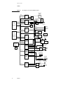
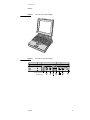
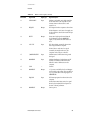
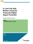
Developer Note Macintosh PowerBook 160 and Macintosh PowerBook 180 Developer Note Developer Technical Publications © Apple Computer, Inc. 2000 Apple Computer, Inc. © 2000, Apple Computer, Inc. All rights reserved. No part of this publication may be reproduced, stored in a retrieval system, or transmitted, in any form or by any means, mechanical, electronic, photocopying, recording, or otherwise, without prior written permission of Apple Computer, Inc. Printed in the United States of America. The Apple logo is a registered trademark of Apple Computer, Inc. Use of the “keyboard” Apple logo (Option-Shift-K) for commercial purposes without the prior written consent of Apple may constitute trademark infringement and unfair competition in violation of federal and state laws. No licenses, express or implied, are granted with respect to any of the technology described in this book. Apple retains all intellectual property rights associated with the technology described in this book. This book is intended to assist application developers to develop applications only for Apple Macintosh computers. Apple Computer, Inc. 20525 Mariani Avenue Cupertino, CA 95014 408-996-1010 Apple, the Apple logo, AppleLink, AppleTalk, APDA, LaserWriter, and Macintosh are trademarks of Apple Computer, Inc., registered in the United States and other countries. Apple Desktop Bus, Apple SuperDrive, Macintosh Quadra, and PowerBook are trademarks of Apple Computer, Inc. Adobe Illustrator and PostScript are trademarks of Adobe Systems Incorporated, which may be registered in certain jurisdictions. FrameMaker is a registered trademark of Frame Technology Corporation. Helvetica and Palatino are registered trademarks of Linotype Company. ITC Zapf Dingbats is a registered trademark of International Typeface Corporation. NuBus is a trademark of Texas Instruments. Varityper is a registered trademark of Varityper, Inc. Simultaneously published in the United States and Canada. LIMITED WARRANTY ON MEDIA AND REPLACEMENT If you discover physical defects in the manual or in the media on which a software product is distributed, APDA will replace the media or manual at no charge to you provided you return the item to be replaced with proof of purchase to APDA. ALL IMPLIED WARRANTIES ON THIS MANUAL, INCLUDING IMPLIED WARRANTIES OF MERCHANTABILITY AND FITNESS FOR A PARTICULAR PURPOSE, ARE LIMITED IN DURATION TO NINETY (90) DAYS FROM THE DATE OF THE ORIGINAL RETAIL PURCHASE OF THIS PRODUCT. Even though Apple has reviewed this manual, APPLE MAKES NO WARRANTY OR REPRESENTATION, EITHER EXPRESS OR IMPLIED, WITH RESPECT TO THIS MANUAL, ITS QUALITY, ACCURACY, MERCHANTABILITY, OR FITNESS FOR A PARTICULAR PURPOSE. AS A RESULT, THIS MANUAL IS SOLD “AS IS,” AND YOU, THE PURCHASER, ARE ASSUMING THE ENTIRE RISK AS TO ITS QUALITY AND ACCURACY. IN NO EVENT WILL APPLE BE LIABLE FOR DIRECT, INDIRECT, SPECIAL, INCIDENTAL, OR CONSEQUENTIAL DAMAGES RESULTING FROM ANY DEFECT OR INACCURACY IN THIS MANUAL, even if advised of the possibility of such damages. THE WARRANTY AND REMEDIES SET FORTH ABOVE ARE EXCLUSIVE AND IN LIEU OF ALL OTHERS, ORAL OR WRITTEN, EXPRESS OR IMPLIED. No Apple dealer, agent, or employee is authorized to make any modification, extension, or addition to this warranty. Some states do not allow the exclusion or limitation of implied warranties or liability for incidental or consequential damages, so the above limitation or exclusion may not apply to you. This warranty gives you specific legal rights, and you may also have other rights which vary from state to state. Contents Figures and Tables Preface v About This Developer Note vii Supplementary Documents vii Conventions and Abbreviations viii Typographical Conventions viii Standard Abbreviations viii Chapter 1 Hardware 1 Introduction 2 Features 2 Compatibility Issues 6 LCD Changes 6 Video Output 6 RAM Expansion Slot 7 New Modem Interface 7 SCSI Disk Mode 7 Soft Shutdown Control 7 Internal Microphone 8 Hardware Overview 9 Main Processor 9 Memory Mapping 9 Custom Integrated Circuits 11 CPU GLU 11 Miscellaneous GLU 11 GSC (Gray Scale Controller) 12 Video Controller 12 VIA Functions 12 ROM 12 ROM Overlay 12 ROM Wait States 12 RAM 13 RAM Wait States 13 Battery Backup 13 Floppy Disk Interface 14 Serial and SCSI Interfaces 15 Serial Communication Controller (SCC) SCSI Controller 15 SCSI Disk Mode 17 15 iii Internal Hard Disk 17 Hard Disk Design Guidelines 17 Power Budget 17 Dimensions and Mounting Requirements 18 Sound System 19 Power Manager 19 Power States 20 Internal Display Interface 21 LCD Screen 21 External Video Interface 21 Monitors Supported 22 External Video Connector and Adapter Cable 22 Monitor Sense Codes 24 RAM Expansion Interface 25 RAM Expansion Electrical Interface 25 /FASTRAM 25 /ROM.CS.EXP 26 RAM Chip Selects 26 Designing Compatible RAM Expansion Cards 31 Designing Fast RAM Expansion Cards 31 Modem Expansion Interface 33 Modem Electrical Interface 33 Modem Power Control 36 Modem Card Power Budget 36 Security Connector 37 Chapter 2 Software 39 ROM Software 40 Gray Scale and External Video Support 40 Mouse Driver Changes 40 Serial Driver Changes 40 SPI Modem Support 40 SCSI Disk Mode 41 System Software 41 Identifying the PowerBook 160/180 41 Sound Input Changes 41 New Control Panels 41 iv Figures and Tables Chapter 1 Chapter 2 Hardware 1 Figure 1-1 Figure 1-2 Figure 1-3 Figure 1-4 Figure 1-5 Figure 1-6 Figure 1-7 Figure 1-8 Figure 1-9 Block diagram of the PowerBook 160/180 computers Front view of the PowerBook 160/180 5 Back view of the PowerBook 160/180 5 32-bit memory and detailed I/O map 10 32-bit and 24-bit memory map comparison 11 Hard disk drive dimensions 18 Video connector pinout 23 RAM expansion connector pinout 30 RAM expansion card design guide 32 Table 1-1 Table 1-2 Table 1-3 Table 1-4 Table 1-5 Table 1-6 Table 1-7 Table 1-8 Table 1-9 Table 1-10 Internal floppy disk connector signals 14 Serial port signals 15 Internal and external HDI-30 SCSI connector signals Hard disk power budget 17 Power states 20 Video output modes 22 Video connector signals 23 Recognized monitor sense codes 24 RAM expansion connector signals 27 Modem connector signals 34 Software Figure 2-1 Figure 2-2 Figure 2-3 Figure 2-4 4 16 39 PowerBook control panel 42 PowerBook control panel options 42 PowerBook Display control panel 43 AutoRemounter control panel 43 v P R E F A C E About This Developer Note This document describes the Macintosh PowerBook 160 and Macintosh PowerBook 180 computers, emphasizing those features that are new or different from previous Macintosh PowerBook computers. It is written primarily for experienced Macintosh hardware and software developers who want to create products that are compatible with these new computers. If you are unfamiliar with the Macintosh or would simply like more technical information on the hardware, you may want to read the related technical manuals listed in the following section. Supplementary Documents 0 To supplement the information in this document, you might wish to obtain related documentation such as Guide to the Macintosh Family Hardware, second edition, Designing Cards and Drivers for the Macintosh Family, third edition, and Inside Macintosh. The Macintosh PowerBook 100, 140, 145, and 170 developer notes provide information about these similar models that may also be of interest to you. For detailed information about the Motorola 68030 microprocessor used in the PowerBook 160 and PowerBook 180 computers, refer to the MC68030 Enhanced 32-Bit Microprocessor User’s Manual. All of these documents are available through APDA. APDA is Apple’s worldwide source for over 300 development tools, technical resources, training products, and information for anyone interested in developing applications on Apple platforms. To place an order or request a complimentary copy of the APDA Tools Catalog, contact APDA Apple Computer, Inc. P.O. Box 319 Buffalo, NY 14207-0319 U.S.: 800-282-2732 Canada: 800-637-0029 International: 716-871-6555 FAX: 716-871-6511 AppleLink: APDA America Online: APDA CompuServe: 76666,2405 Internet: [email protected] vii P R E F A C E Conventions and Abbreviations 0 This developer note uses abbreviations and typographical conventions that are standard in Apple publications. Typographical Conventions 0 This note uses the following typographical conventions. New terms appear in boldface where they are first defined. Computer-language text—any text that is literally the same as it appears in computer input or output—appears in Courier font. Standard Abbreviations 0 When unusual abbreviations appear in this book, the corresponding terms are also spelled out. Standard units of measure and other widely-used abbreviations are not spelled out. Standard units of measure used in Apple reference books include: A amperes MB megabytes GB gigabytes MHz megahertz Hz hertz ms milliseconds K 1024 ns nanoseconds KB kilobytes V volts mA milliamperes W watts Standard abbreviations used in Apple reference books include: viii $n hexadecimal value n AC alternating current ADB Apple Desktop Bus CLUT color look-up table DAC digital-to-analog converter IC integrated circuit ASIC application-specific integrated circuit MMU memory-management unit RAM random-access memory ROM read-only memory RGB red-green-blue (a video display system used by Apple computers) P R E F A C E SCSI small computer system interface SVGA super VGA (a video display system used with PC-type computers) VGA video graphics adapter (a video display system used with PC-type computers) VRAM video RAM ix C H A P T E R Figure 1-0 Listing 1-0 Table 1-0 1 Hardware 1 C H A P T E R 1 Hardware This chapter describes the major features of the Macintosh PowerBook 160 and PowerBook 180 computers, emphasizing the similarities and differences between these and other Macintosh PowerBook computers. To ensure that your hardware and software is compatible with other members of the PowerBook family, you should read the developer notes for the PowerBook 100, 140, 145, and 170. See the Preface for information about ordering these documents. Introduction 1 The PowerBook 160 and PowerBook 180 computers are the newest additions to the Macintosh PowerBook family of notebook computers. They offer improved performance, enhanced displays, video output, greater memory expansion capability, and other refinements. Features 1 The major features of the PowerBook 160 and PowerBook 180 computers are: ■ Microprocessor: Motorola 68030 running at 33 MHz (PowerBook 180) or 25 MHz (PowerBook 160). Both computers also offer a 16 MHz power saving mode. ■ Coprocessor: the PowerBook 180 includes a Motorola 68882 FPU running at 33 MHz. ■ Read-only memory (ROM): 1 MB. ■ Random-access memory (RAM): 4 MB of pseudostatic RAM (PSRAM) soldered to the main logic board. ■ RAM expansion: a RAM expansion slot accommodates RAM expansion cards of up to 10 MB, for a total of 14 MB RAM. ■ Liquid Crystal Display (LCD): 4-bit video capability for 16 shades of gray on the built-in 640 x 400 pixel LCD. The PowerBook 180 uses a transreflective active matrix LCD, while the PowerBook 160 uses a transmissive mode FSTN LCD. Both displays are backlit by a cold cathode fluorescent lamp (CCFL). ■ Video output: 8-bit video output circuitry supports 256 colors on all Apple monitors up to 16-inches in size, and 16 shades of gray on the Apple Portrait monitor. VGA and some SVGA modes are supported with appropriate adapter cables. There are two video output modes: dual mode and mirror mode. In dual mode the LCD and external monitor are independent. In video mirror mode, the image on the external monitor is identical to what is displayed on the LCD, but in color. 2 ■ Floppy disk: one internal 1.4 MB Apple SuperDrive with Super Woz Integrated Machine (SWIM) interface. ■ Hard disk: one internal 2.5-inch SCSI (Small Computer System Interface) hard disk drive. Disk capacities of 40, 80, and 120 MB are offered. Introduction C H A P T E R 1 Hardware ■ SCSI disk mode: by connecting an HDI-30 SCSI Disk Adapter cable users can access the PowerBook’s internal hard disk from another Macintosh. ■ I/O (input/output): one HDI-30 connector for external SCSI devices, one 4-pin mini-DIN Apple Desktop Bus (ADB) port, two 8-pin mini-DIN serial ports, audio input and output jacks, custom video output connector with adapter for attaching standard Apple video cables. ■ Sound: enhanced Apple Sound Chip (ASC) audio circuitry provides sound input and output through the built-in microphone and speaker. Stereo sound output can be heard through the headphone jack. ■ Keyboard: built-in keyboard with integral 30-mm trackball. ■ Modem: internal 20-pin connector for an optional modem card. This slot is physically and electrically compatible with previous PowerBook modems, while offering a new interface for faster modems. ■ Battery: a 2.8 ampere-hour NiCad rechargeable battery is included. A 3 V lithium battery provides backup power for the real-time clock and parameter RAM when the main battery is removed. ■ Power supply: an external wall-mounted recharger/power adapter is included. ■ Security connector: a connector on the back panel allows users to attach a security device. ■ Weight: 6.8 pounds. ■ Size: 11.3 inches wide, 9.3 inches deep, and 2.25 inches high. The block diagram shown in Figure 1-1 illustrates the major hardware components of the PowerBook 160 and PowerBook 180 computers. Figures 1-2 and 1-3 show front and back views of the computers. Features 3 C H A P T E R 1 Hardware Figure 1-1 Block diagram of the PowerBook 160/180 computers Flat-panel display A14–1 D31–16 GSC Video RAM A12–9 CPU Address bus A31–0 MC68030 Data bus D31–0 D31-24 A23-0 Video controller A20-0 CLUT Video RAM D31-16 Monitor connector OSC A20–2 RAM expansion connector A20–2 D31–0 D31–0 PSRAM 2 MB Trackball D31–0 MC68882 PowerBook 180 only RTC D31–0 Address buffers A4–1 FPU VIA1 D31–24 Data bus D31–0 D31–24 I/O data buffer A19–2 Power Manager CPU GLU Battery charger and power supply Apple Desktop Bus port D31–24 D25, 24 A31–13, 1, 0 ROM 1 MB Keyboard controller Internal modem connector D31–24 Misc. GLU Port A Drivers (modem) and Channel B receivers Port B (printer) Channel A Battery A6–4, 2, 1 Combo SCC/SCSI SWIM Internal floppy disk connector Internal hard disk connector Sound input jack A11–0 Enhanced ASC Features External SCSI port External sound jack DFAC Filter/amp 4 Serial ports D31–24 D31–24 A12–9 Keyboard Internal speaker C H A P T E R 1 Hardware Figure 1-2 Front view of the PowerBook 160/180 Figure 1-3 Back view of the PowerBook 160/180 K * RJ-11 connector for optional modem Features 5 C H A P T E R 1 Hardware Compatibility Issues 1 The PowerBook 160 and PowerBook 180 incorporate several significant changes from earlier PowerBook designs. This section highlights key areas you should investigate in order to ensure that your hardware and software works properly with these new computers. These topics are covered in more detail in subsequent sections. LCD Changes 1 The LCD display system now supports 1-, 2-, and 4-bit modes. In addition, the frame buffer has moved from $FE00 0000 to $6000 0000 and occupies 128 KB instead of 32 KB. Although the internal display supports multiple bit depths, it does not use a color look-up table (CLUT). It is a fixed device, meaning the color table is defined by the hardware and cannot be changed. This distinction is transparent to software that uses the Palette Manager. Software that attempts to directly modify the color table may not be compatible. Refer to Inside Macintosh for more information about fixed versus CLUT devices. See the “Internal Display Interface” section on page 21 for more information about the internal display hardware and LCD screen. Video Output 1 The video output system is designed to emulate a NuBus video card in slot $E. The video output circuitry consists of a video controller chip, dedicated 512 KB VRAM frame buffer, and a CLUT. A custom video output connector is used to conserve space on the back panel. An adapter cable provided with each unit allows users to connect standard Apple monitor cables. In normal operation the video output circuitry acts like a second monitor to extend the user’s desktop. Alternatively, the user can select video mirroring mode, in which the external monitor mirrors the internal LCD. In video mirroring mode, software blanks the edges of the larger screen to match the horizontal and vertical pixel resolution of the smaller screen. Because video mirroring is a software feature, there are no hardware protections to prevent applications from writing to screen regions that are off limits. Applications that write directly to the frame buffer may not be compatible with video mirroring unless precautions are taken to ensure that all screen manipulation is within the active region. See “External Video Interface” on page 21 for more information about the video output circuitry. 6 Compatibility Issues C H A P T E R 1 Hardware RAM Expansion Slot 1 The RAM expansion slot is compatible with RAM expansion cards meeting Apple design specifications for the PowerBook 100/140/145/170. However, cards designed specifically for the PowerBook 160 and PowerBook 180 can provide more memory and faster performance. To remain compatible with earlier Macintosh PowerBook computers, RAM expansion cards cannot contain more than 6 MB of RAM. If backward compatibility is not required, cards can contain up to 10 MB of RAM. The “RAM Expansion Interface” section on page 25 provides physical and electrical design guidelines for RAM expansion cards. New Modem Interface 1 In addition to the standard serial interface, the PowerBook 160 and PowerBook 180 support a new modem interface designed for high speed communication. This new interface is based on the Motorola serial peripheral interface (SPI). To maintain compatibility with existing Apple and third party modems, the PowerBook 160 and PowerBook 180 incorporate both the standard RS-232 serial interface and the new SPI interface by multiplexing several signals on the modem connector. Pin 16 selects which interface is used, and must be disconnected or tied to ground for existing modems to operate. Refer to the “Modem Expansion Interface” section on page 33 for information about the modem interface. SCSI Disk Mode 1 The PowerBook 160 and PowerBook 180 implement a SCSI disk mode identical to the Macintosh PowerBook 100. This mode allows the computer to act like an external hard disk when attached to another Macintosh. To enter SCSI disk mode, the user selects a SCSI ID number using the PowerBook control panel, then restarts the computer with a SCSI Disk Adapter cable connected to another Macintosh. See the section “SCSI Disk Mode” on page 41 for more information. Compatibility Issues 7 C H A P T E R 1 Hardware Soft Shutdown Control 1 The PowerBook 160 and PowerBook 180 implement a “soft shutdown” feature. If the user presses the back-panel power button while the computer is on, the Power Manager IC sends an interrupt to the CPU that initiates a shutdown, just as if the user had selected Shut Down from the Special menu. Pressing the power button for five seconds will bypass the soft shutdown procedure and force the computer to turn off in cases where the CPU is “hung.” Power control is covered in more detail in the “Power Manager” section on page 19. Internal Microphone The PowerBook 160 and PowerBook 180 include a built-in microphone located behind the speaker grille. To avoid feedback, sound play-through is disabled when recording with the internal microphone. Play-through is possible when an external microphone is used. See the “Sound System” section on page 19 for more information about the sound system. 8 Compatibility Issues 1 C H A P T E R 1 Hardware Hardware Overview 1 This section provides a functional description of the processor, memory, general logic, and I/O (input/output) interface systems. Emphasis is placed on systems that are new or different from those of earlier Macintosh PowerBook computers. IMPORTANT Memory sizes, addresses, and other data are specific to each type of Macintosh computer and are provided for informational purposes only. To ensure that your application software maintains compatibility across the Macintosh line and to allow for future hardware changes, you are strongly advised to use the Macintosh Toolbox and Operating System routines wherever provided. In particular, never use absolute addresses to access hardware, because these addresses are not the same for all models. ▲ Main Processor 1 The 68030 microprocessors used in the PowerBook 160 and PowerBook 180 run at system clock rates of 25 MHz and 33 MHz, respectively. The 68030 includes a built-in MMU (memory management unit) that performs the necessary memory-mapping functions. Floating-point operations in the PowerBook 180 are provided by the 68882 mathematics coprocessor FPU. The PowerBook 160 does not include an FPU. Memory Mapping 1 Like the PowerBook 140/145/170, the PowerBook 160 and PowerBook 180 always operate in 32-bit addressing mode. To maintain compatibility with software that uses 24-bit addressing conventions, the memory management unit (MMU) in the 68030 is used to map 24-bit addresses to their 32-bit equivalent. In 32-bit mode, the 68030 supports a 4 GB address space. In 24-bit mode, however, the upper 8 address bits are ignored, and the maximum address space is limited to 16 MB. The MMU remaps addresses so that RAM, ROM, VRAM, and I/O all appear within this 16 MB range. Although the address translation is transparent to software, it has the effect of limiting the amount of addressable RAM to 8 MB. Figure 1-4 shows the 32-bit memory map used by the PowerBook 160 and PowerBook 180. Figure 1-5 compares the 24-bit and 32-bit memory maps. Note that the LCD frame buffer is not addressable in 24-bit mode. Hardware Overview 9 C H A P T E R 1 Hardware Figure 1-4 32-bit memory and detailed I/O map $6000 0000 Expansion I/O space (no DSACKs) Reserved Reserved Reserved CPU GLU registers $FFFF FFFF $FEF0 FFFF $FE00 0000 Reserved Slot E (external video) Reserved Reserved Reserved Reserved Reserved Reserved Reserved $7000 0000 $6000 0000 $5000 0000 $4400 0000 $4000 0000 LCD frame buffer I/O Reserved ROM Reserved Reserved Reserved GSC registers Reserved Reserved Expansion RAM (bus error) Reserved Reserved SWIM $0400 0000 $00E0 0000 $0000 0000 Illegal RAM 14 MB maximum, one continuous bank Sound SCSI (non DRQ) SCSI (normal mode) Reserved (SCSI wrap) Reserved (SCC wrap) Reserved (VIA2 wrap) Reserved (VIA1 wrap) SCSI (DMA with DRQ) SCC VIA2 VIA1 10 Hardware Overview $5900 0000 $5400 0000 $5010 0000 $500C 0000 $5008 0000 $5004 0000 $5003 0000 $5002 E000 $5002 C000 $5002 A000 $5002 8000 $5002 6000 $5002 4000 $5002 2000 $5002 0000 $5001 E000 $5001 C000 $5001 A000 $5001 8000 $5001 6000 $5001 4000 $5001 2000 $5001 0000 $5000 E000 $5000 C000 $5000 A000 $5000 8000 $5000 6000 $5000 4000 $5000 2000 $5000 0000 C H A P T E R 1 Hardware Figure 1-5 32-bit and 24-bit memory map comparison 32-bit memory map $FFFF FFFF Reserved $FEF0 FFFF $FE00 0000 24-bit memory map $FF FFFF Slot E (external video) $F0 0000 $E0 0000 I/O space Slot E (external video) Reserved Reserved $7000 0000 $6000 0000 LCD frame buffer I/O $5000 0000 $4400 0000 $90 0000 $80 0000 ROM Reserved ROM $4000 0000 Expansion RAM (bus error) RAM 8 MB maximum, one continuous bank $0400 0000 Illegal $00E0 0000 $0000 0000 RAM 14 MB maximum, one continuous bank $00 0000 Custom Integrated Circuits 1 This section describes the four new ASICs (application-specific integrated circuits) used in the PowerBook 160 and PowerBook 180. CPU GLU 1 The CPU GLU is a custom chip that generates the CPU clocks and DSACK (data acknowledgment) signals, prioritizes and encodes interrupts, and serves as the interface to the ROM, RAM, SCC, SCSI, VIA1, FPU, SWIM, GSC, and video controller chips. This chip is an enhanced version of the CPU GLU used in the PowerBook 140/145/170. It supports faster processor speeds and up to 16 MB of RAM. Miscellaneous GLU 1 The Miscellaneous GLU is a modified version of the Miscellaneous GLU used in the PowerBook 140/145/170. The Miscellaneous GLU chip emulates the I/O capabilities of VIA2, handles modem/serial port multiplexing, and provides clocking for the Power Manager, SWIM, SCC, ADB, and sound circuits. This chip also supports the new SPI modem interface. Hardware Overview 11 C H A P T E R 1 Hardware GSC (Gray Scale Controller) 1 The GSC provides the interface to the LCD. It performs all the functions of the display driver chip (DDC) used in the PowerBook 140/145/170, and also supports gray scale display. The GSC generates horizontal and vertical synchronization pulses and all other signals required by the LCD. The GSC also supports its own 128K x 8-bit frame buffer and generates the necessary VRAM refresh signals. Video Controller 1 A single-chip video controller provides video output that supports all Apple monitors 16-inches or smaller. The video controller generates the dot clock and synchronization signals that are supplied to the CLUT chip, as well as VRAM refresh signals for its own 512 KB frame buffer. VIA Functions 1 The hardware includes a VIA1 and a pseudo-VIA2. VIA1 provides some I/O control, generates various interrupts, and ensures compatibility with existing Macintosh software. The Miscellaneous GLU chip provides VIA2 functionality similar to that of the RBV (RAM-based video) chip in the Macintosh IIci. ROM 1 The PowerBook 160 and PowerBook 180 contain a new 1 MB ROM implemented as a 256K x 32-bit array consisting physically of two 256K x 16-bit chips with an access time of 150 ns. The ROM is located in the system memory map between addresses $4080 0000 and $408F FFFF. Although the ROM code is new, this configuration is the same as the PowerBook 140/145/170. ROM Overlay 1 Like all Macintosh computers, the PowerBook 160 and PowerBook 180 implement an overlay function at startup that maps ROM address space (in this case $4080 0000– $408F FFFF) to RAM space starting at $0000 0000. This overlay allows the 68030 processor to address a standard default set of exception vectors and trap addresses as well as a starting address at which to begin executing code. Following the first access to the normal ROM address range, the ROM image at $0000 0000 is cleared and replaced by RAM. ROM Wait States ROM accesses by the CPU in the PowerBook 180 require 4 processor wait states (7 clock cycles at 33 MHz), which is equivalent to 180 ns per access. In the PowerBook 160, ROM access requires 3 processor wait states (6 clock cycles at 25 MHz), or 200 ns. 12 Hardware Overview 1 C H A P T E R 1 Hardware RAM 1 The PowerBook 160 and PowerBook 180 include 4 MB of 85 ns pseudostatic RAM on the secondary logic board, consisting of eight 512K x 8-bit chips. In addition, the RAM expansion slot supports up to 10 MB of PSRAM, for a total of 14 MB. See the “RAM Expansion Interface” section on page 25 for information about designing RAM expansion cards. RAM is always contiguous because only one size of RAM chip (4 Mbits) is used. As a result, software does not have to “stitch” memory. The RAM array is located in the system memory map between addresses $0000 0000 and $00DF FFFF, except following a system reset or sleep cycle, when it is overlaid by system ROM. However, the overlay is removed following access to normal ROM space, and the RAM space is then accessible. Both RAM and ROM memory spaces provide DSACK signals to the processor even if memory is not actually installed. The RAM data path is 32 bits wide. RAM Wait States 1 RAM accesses require 2 wait states in both the PowerBook 160 and PowerBook 180 when using 85 ns PSRAM exclusively. Installing 100 ns expansion RAM in the PowerBook 180 causes the memory controller to insert an additional wait state in all memory accesses (both main and expansion). The PowerBook 160 can use 100 ns expansion RAM without causing an added wait state. Battery Backup 1 Both main and expansion RAM are backed up when the computer is in the sleep state, as long as the battery is charged or the power adapter is plugged in. RAM contents are not maintained when the computer is turned off or when the battery is removed. Hardware Overview 13 C H A P T E R 1 Hardware Floppy Disk Interface 1 The floppy disk interface is identical to the PowerBook 140/145/170 computers. Table 1-1 shows the signal assignments for the internal floppy disk connector. Table 1-1 14 Internal floppy disk connector signals Pin number Signal name Signal description 1 GND Ground 2 PH0 Phase 0: state control line 3 GND Ground 4 PH1 Phase 1: state control line 5 GND Ground 6 PH2 Phase 2: state control line 7 GND Ground 8 PH3 Phase 3: register write strobe 9 /SYS.PWR System power 10 /WREQI Write data request 11 FD1.+5V/0 +5 V/0 V (awake/sleep) 12 HDSELI Head select 13 FD1.+5V/0 +5 V/0 V (awake/sleep) 14 /DISK1EN Drive enable 15 FD1.+5V/0 +5 V/0 V (awake/sleep) 16 RD Read data 17 FD1.+5V/0 +5 V/0 V (awake/sleep) 18 WRDATA Write data 19 n.c. Not connected 20 n.c. Not connected Floppy Disk Interface C H A P T E R 1 Hardware Serial and SCSI Interfaces 1 The PowerBook 160 and PowerBook 180 use the same custom serial communication and SCSI controller chip as earlier PowerBook computers. The Combo chip is completely software compatible with the SCC (85C30) and SCSI (53C80) chips it replaces. Serial Communication Controller (SCC) 1 The SCC portion of the Combo chip includes two independent ports for serial communication. Each port can be independently programmed for asynchronous, synchronous, or AppleTalk protocols. The two 8-pin mini-DIN connectors are the same as those on other Macintosh computers. Table 1-2 shows the signal assignments for the serial ports. Table 1-2 Serial port signals Pin number Signal name Signal description 1 HSKo Handshake output 2 HSKi Handshake input 3 TxD– Transmit data – 4 SG Signal ground 5 RxD– Receive data – 6 TxD+ Transmit data + 7 GPi General-purpose input 8 RxD+ Receive data + SCSI Controller 1 The SCSI portion of the Combo chip is completely compatible with the SCSI controller chip used on other members of the Macintosh family. It is designed to support the SCSI interface as defined by the American National Standards Institute (ANSI) X3T9.2 committee. The internal and external HDI-30 connectors are identical to those used on the PowerBook 140/145/170. The SCSI portion of the Combo chip connects directly to the internal and external SCSI connectors and can sink up to 48 mA through each of the pins connected to the SCSI bus. The data and control signals on the SCSI bus are active low signals that are driven by open drain outputs. Table 1-3 shows the signal assignments for the internal and external SCSI connectors. Note that pin 1 of the external HDI-30 connector is now the SCSI Disk Mode signal. Serial and SCSI Interfaces 15 C H A P T E R 1 Hardware Table 1-3 16 Internal and external HDI-30 SCSI connector signals Pin number HDI-30 (internal) HDI-30 (external) 1 DISK.+5 /SCSI Disk Mode 2 DISK.+5 /DB0 3 GND GND 4 GND /DB1 5 GND TERMPWR (not used; reserved for future use) 6 /DB0 /DB2 7 /DB1 /DB3 8 /DB2 GND 9 /DB3 /ACK 10 /DB4 GND 11 /DB5 /DB4 12 /DB6 GND 13 /DB7 GND 14 /DBP /DB5 15 DISK.+5 GND 16 /BSY /DB6 17 /ATN GND 18 /ACK /DB7 19 GND /DBP 20 /MSG GND 21 /RST /REQ 22 /SEL GND 23 /C/D /BSY 24 /I/O GND 25 /REQ /ATN 26 GND /C/D 27 GND /RST 28 GND /MSG 29 DISK.+5 /SEL 30 DISK.+5 /I/O Serial and SCSI Interfaces C H A P T E R 1 Hardware SCSI Disk Mode 1 The PowerBook 160 and PowerBook 180 implement a SCSI disk mode similar to that of the PowerBook 100 computer, allowing the internal hard disk to be mounted and used as an external drive by another Macintosh. To enter SCSI disk mode you connect an HDI-30 SCSI Disk Adapter cable between the PowerBook’s external SCSI connector and the desktop computer, and then restart the system. The adapter cable grounds pin 1 of the HDI-30 connector, causing the ROM code to bypass the normal startup procedure and enter SCSI disk mode. See Chapter 2, “Software” for more information. Internal Hard Disk 1 The PowerBook 160 and PowerBook 180 include an internal 2.5-inch hard disk drive that connects to the computer through the HDI-30 internal SCSI connector. Apple will offer a range of disk capacities to meet customer needs. Hard Disk Design Guidelines 1 The following information is provided as a general guideline and is based on the specifications for Apple’s 2.5-inch, 80 MB hard disk drive. Power Budget 1 The hard disk drive operates on 5 VDC ± 5 percent. Voltage ripple tolerance is 100 mV peak-to-peak from DC to 10 MHz. Table 1-4 shows the maximum and mean current drain and power consumption for various operating modes of the Apple 80 MB hard disk drive. These limits include 1 KΩ pull-up terminator resistors on all signal lines. All mean specifications are RMS (root mean square) values. Table 1-4 Hard disk power budget Current (amps) Mode Power (watts) Mean Max. Mean Max. Startup* — 1.000 — 5.000 Operation 0.500 0.700 2.500 3.500 Idle 0.300 0.400 1.500 2.000 Standby 0.200 0.250 1.000 1.250 Shutdown 0.050 0.075 0.250 0.380 * Peak values between power-on and drive ready (not more than 5 seconds). Internal Hard Disk 17 C H A P T E R 1 Hardware Dimensions and Mounting Requirements 1 Figure 1-6 shows the drive and connector envelope requirements for the hard disk drive. The drive and its mating connectors are constrained to the envelope shown. The drive is mounted with a spring force bracket that contacts the top cover in four points directly above the mounting posts of the drive chassis. Figure 1-6 Hard disk drive dimensions Bottom view (PCB side) 34.93±0.38 (1.375±0.15) 101.60 Max. (4.00 Max.) 38.10 (1.500) 30-PIN SCSI connector 70.00 (2.76) 61.72 (2.43) End view CL 2.00 (0.079) Connector envelope 9.83±0.30 (0.387±0.012) Connector position Bottom mounting holes M 3.0 (4X) Side view 15.6 Max. (0.614 Max.) 3.00 (0.118) 0.00 34.93±0.38 (1.375±0.15) 18 Internal Hard Disk 38.10 (1.500) Side mounting holes M 3.0 (4X) C H A P T E R 1 Hardware Sound System 1 The sound system includes a built-in microphone and speaker as well as external microphone and stereo headphone jacks. The on-board sound input and output capabilities of the PowerBook 160/180, combined with a new type of modem described in the “Modem Expansion Interface” section on page 33, allow developers to create new uses for the computer, such as a hands-free speaker phone or telephone answering machine. The sound circuitry is based on enhanced versions of the Apple Sound Chip (ASC) and Digitally Filtered Audio Chip (DFAC). Aside from the addition of an internal microphone and sound output to the modem, the PowerBook 160/180 sound hardware is identical to the PowerBook 140/145/170 hardware. The internal microphone is selected by default when no external microphone is plugged in. When an external microphone is plugged in, it is automatically selected. To prevent feedback between the internal microphone and speaker, the play-through mode is disabled when recording with the internal microphone. Play-through mode can be enabled when using an external microphone. Refer to Inside Macintosh for more information about play-through mode and the Sound Manager in general. Power Manager 1 The Power Manager hardware in the PowerBook 160 and PowerBook 180 is the same as the PowerBook 140/145/170. The Power Manager communicates with the main processor using an asynchronous handshake mechanism and an 8-bit parallel data bus in conjunction with VIA2. The Power Manager provides the following functions: ■ Power management activities (for example, enabling or disabling clocks to I/O devices such as the SWIM chip to reduce power consumption during idle or sleep periods and physically enabling or disabling various power planes). ■ Transceiver functions for the Apple Desktop Bus (ADB). ■ Generates the brightness level (via the PWM function) for the inverter to control the backlight brightness of the display. ■ Monitors the level of the battery charge to warn the user if the voltage becomes too low, or if the computer should shut down in order to preserve its memory contents. ■ Monitors whether the system is in sleep or shutdown mode, depending on whether the charger is plugged in, and whether the user has pushed the power on/off button. ■ Provides sleep mode control, system reset control, and several signals that support the modem. Sound System 19 C H A P T E R 1 Hardware Power States 1 There are three power states: Power On, Sleep, and Power Off (Shutdown). The power on/off button, the reset button, the keyboard, or a Finder command can control the power state of the machine. Table 1-5 lists the starting states, the actions that cause the starting states to change, and the ending states that result from each action. Table 1-5 Power states Starting state Action Ending state Power off Press power button Power on Power on Issue shutdown command Power off (after shutdown) Power on Press power button Power off (after shutdown) Power on Hold power button more than 5 seconds Power off (immediate) Power on Issue sleep command Sleep Sleep Press any key Power on Sleep Press power button Power on Sleep Detect extremely low power condition Power off Power off Insert charger Power off and charging If you are writing an application that includes the ability to put the computer into the sleep state, you must use the Sleep trap rather than directly addressing the Power Manager trap. Note For a description of the operating system calls associated with the Power Manager’s “sleep” function, see the Power Manager section of Inside Macintosh, Volume VI. ◆ 20 Power Manager C H A P T E R 1 Hardware Internal Display Interface 1 The internal display interface consists of the GSC chip and 128 KB of VRAM. The GSC, which replaces the DDC used in the PowerBook 140/145/170, supports 1-, 2-, and 4-bit display modes and generates all the vertical and horizontal synchronization pulses required by the LCD. The GSC also manages the frame buffer and generates the necessary VRAM refresh signals. The 68030 accesses the frame buffer as a continuous RAM array of 128 KB beginning at $6000 0000. The 128 KB frame buffer “wraps” to fill the entire range between $6000 0000 and $7000 0000, and DSACKs are generated for accesses anywhere in this area. The VRAM data path is 16 bits wide and byte addressable. Because these are the first portable Macintosh computers to support gray scale display, developers should test their applications to ensure that they are compatible with 2-bit and 4-bit modes and that their choice of colors/grays looks acceptable on the LCD screen. LCD Screen 1 The PowerBook 180 uses an active matrix screen that provides a high-contrast 640 x 400 pixel image in a 217 x 140 mm active display area. The PowerBook 160 uses an FSTN display with the same dimensions. Both displays include on-demand CCFL backlighting. External Video Interface 1 The video output system consists of the video controller chip, 512 KB of VRAM, and a CLUT/DAC chip. The video controller emulates a NuBus card in slot $E, so the video output system appears to software as a standard video card. The 256K x 16-bit frame buffer is located at $FE10 0000. The VRAM data path is 16 bits wide and byte addressable. The video controller supports 8-bit video output for 256 colors on Apple 12-inch, 13-inch, and 16-inch RGB monitors; and 4-bit video with 16 shades of gray on the Apple Portrait monitor. VGA and SVGA modes are supported with appropriate adapter cables. The external video interface is enabled by attaching a monitor and restarting the computer. During the boot process, ROM software tests the monitor sense lines and activates the video output system if a recognized monitor is attached. If no monitor is found, the video output system is deactivated to conserve power. In normal operation the video output circuitry acts like a second monitor to extend the user’s desktop. Alternatively, the user can select video mirroring mode, in which the external monitor mirrors the internal LCD. In mirror mode, software blanks the edges of Internal Display Interface 21 C H A P T E R 1 Hardware the larger screen to match the horizontal and vertical pixel resolution of the smaller screen. Because video mirroring is a software feature, there are no hardware protections to prevent applications from writing to screen regions that are off limits. Applications that write directly to the frame buffer may not be compatible with this mode unless precautions are taken to ensure that all screen manipulation is within the active region. Because the video output circuitry consumes additional power, Apple recommends that customers use the AC adapter when using an external monitor. Monitors Supported 1 The PowerBook 160 and PowerBook 180 support the monitors and video modes listed in Table 1-6. Table 1-6 Video output modes Resolution Monitor Dot clock (MHz) Width (pixels) Height (pixels) Depth (bits) 512 384 8 15.6672 640 480 8 30.2400 VGA 640 480 8 25.1750 SVGA 800 600 8 36.000 Portrait 640 870 4 57.2832 16-inch RGB 832 624 8 57.2832 12-inch RGB 13-inch RGB* * Includes Macintosh Color Display, AppleColor High Resolution RGB Monitor, and Apple High Resolution Monochrome Monitor. External Video Connector and Adapter Cable 1 The PowerBook 160 and PowerBook 180 use a new custom video connector called the VID-14. An adapter cable included with the computer allows users to attach a standard Apple video cable. Figure 1-6 shows the pin configuration of the VID-14 connector on the back of the computer and the DB-15 connector on the adapter cable. Table 1-7 lists the signal assignments. One source for the VID-14 adapter cable is Hosiden America Corp. 10090 Pasadena Ave., Suite B2 Cupertino, CA 95014 (408) 252-0541 Refer to Hosiden part number CMP1220-010100. 22 External Video Interface C H A P T E R 1 Hardware Figure 1-7 Video connector pinout 2 4 6 8 10 12 14 1 3 5 7 9 11 13 Female VID-14 connector 8 7 15 6 14 5 13 4 12 3 11 2 10 1 9 Female DB-15 connector Table 1-7 Video connector signals Pin Signal name Description VID-14 DB-15 2 1 RED.GND Red video ground 1 2 RED.VID Red video signal 5 3 /CSYNC Composite synchronization signal 3 4 SENSE0 Monitor sense signal 0 8 5 GRN.VID Green video signal 7 6 GRN.GND Green video ground 9 7 SENSE1 Monitor sense signal 1 — 8 n.c. Not connected 13 9 BLU.VID Blue video signal 11 10 SENSE2 Monitor sense signal 2 6 11 GND CSYNC and VSYNC ground 4 12 /VSYNC Vertical synchronization signal 14 13 BLU.GND Blue video ground 10 14 HSYNC.GND HSYNC ground 12 15 /HSYNC Horizontal synchronization signal Shell Shell SGND Shield ground External Video Interface 23 C H A P T E R 1 Hardware Monitor Sense Codes 1 To identify the type of monitor connected, the external video interface uses the standard Apple monitor sense codes as well as the newer extended sense codes. Table 1-8 shows the sense codes for each of the supported monitors. Refer to the Macintosh Technical Note M.HW.SenseLines for a description of the sense code system. Note that SVGA monitors use the same sense code as VGA monitors. The user selects SVGA mode from the Monitors control panel options. Table 1-8 Monitor 24 Recognized monitor sense codes Standard sense code Extended sense code (2 : 0) (1, 2) (0, 2) (0, 1) 12-inch RGB 010 — — — 13-inch RGB 110 — — — Portrait 001 — — — VGA/SVGA 111 01 01 11 16-inch RGB 111 10 11 01 No monitor 111 11 11 11 External Video Interface C H A P T E R 1 Hardware RAM Expansion Interface 1 The secondary logic board contains a 70-pin RAM expansion connector (slot) that supports RAM expansion cards from 2 MB to 10 MB in size. RAM expansion cards designed for the PowerBook 100/140/145/170 are generally compatible with the PowerBook 160 and PowerBook 180, but impose limitations on performance and maximum RAM expansion. As with earlier members of the PowerBook family, only 4 Mbit (512K x 8-bit) PSRAM chips are used for expansion RAM. The maximum power budget for RAM expansion is 2 watts (400 mA at +5 V). For purposes of this discussion, there are two types of RAM expansion cards: ■ Compatible — cards designed for the PowerBook 100/140/145/170 are compatible with the PowerBook 160/180, but are limited to a maximum of 6 MB of RAM. These cards also impose an extra wait state in the PowerBook 180. ■ Fast — cards designed specifically for the PowerBook 160/180 can contain up to 10 MB of RAM. These cards must use 85 ns PSRAM chips. RAM Expansion Electrical Interface 1 With the exception of two signals, the RAM expansion slot is electrically compatible with that of the PowerBook 140/145/170. This section lists the RAM expansion signals and describes the differences between the PowerBook 160/180 RAM expansion slot and previous PowerBook models. Developers should refer to Designing Cards and Drivers for the Macintosh Family, third edition, for information about RAM expansion in earlier PowerBook computers. /FASTRAM 1 The /FASTRAM signal, pin 46, defines whether the expansion card contains 85 or 100 ns RAM, and also indicates whether the card contains more than 6 MB of memory. The PowerBook 160 and PowerBook 180 can accept up to 10 MB of expansion RAM. However, cards that contain more than 6 MB are not compatible with the PowerBook 100/140/145/170. The /FASTRAM signal is asserted by default in the PowerBook 160/180 (pin 46 is grounded on the logic board). If you design a fast RAM expansion card, you should leave the /FASTRAM signal disconnected so that the PowerBook 160/180 can take full advantage of your card. RAM Expansion Interface 25 C H A P T E R 1 Hardware ▲ WARNING Do not tie /FASTRAM to ground on your RAM expansion card because it will cause a short circuit if the card is used in a PowerBook 100/140/ 145/170. These computers use pin 46 as a +5 V power supply. By leaving this pin disconnected, your card will not cause damage if installed in any other PowerBook. ▲ A compatible RAM expansion card must hold /FASTRAM high. Because pin 46 was designated as a +5 V supply in earlier PowerBooks, existing RAM expansion cards already hold this signal high (assuming all the +5 V pins were bused). Cards that hold /FASTRAM high are presumed to use 100 ns RAM, and will cause the memory controller to insert an extra wait state in the PowerBook 180. /ROM.CS.EXP 1 The ROM chip select signal that was assigned to pin 49 of the PowerBook 140/145/170 RAM expansion slot is not implemented in the PowerBook 160/180. This signal was only useful for implementing ROM cards, and should be left disconnected on expansion cards. RAM Chip Selects 1 The RAM chip select signals listed in Table 1-9 begin with /RAMCS2 because the first two chip selects (/RAMCS0 and /RAMCS1) are used for the built-in 4 MB of RAM on the logic board. When /FASTRAM is asserted, each chip select signal activates one 2 MB RAM bank. For example, a fast 4 MB card activates /RAMCS2 for the first bank and /RAMCS3 for the second. For compatible cards, chip selects are paired in the same way as they are on the PowerBook 140/145/170. Each chip select activates the upper or lower 16 bits of a 2 MB bank. On a 4 MB card, for example, /RAMCS2 and /RAMCS5 are paired for the first bank, and /RAMCS3 and /RAMCS6 are paired for the second bank. Table 1-9 lists the name and description of each of the RAM expansion connector signals. Except for pins 46 and 49, these signals are compatible with the PowerBook 140/170, as described in Designing Cards and Drivers for the Macintosh Family, third edition. Figure 1-8 shows the connector pinout. 26 RAM Expansion Interface C H A P T E R 1 Hardware Table 1-9 RAM expansion connector signals Pin number Signal name Signal description 1 GND Ground 2 GND Ground 3 A20 Address bit 20 (buffered) 4 A17 Address bit 17 (buffered) 5 A18 Address bit 18 (buffered) 6 A19 Address bit 19 (buffered) 7 A16 Address bit 16 (buffered) 8 /LLW Lower write byte 9 A14 Address bit 14 (buffered) 10 /LUW Lower middle write byte 11 A9 Address bit 9 (buffered) 12 A15 Address bit 15 (buffered) 13 A8 Address bit 8 (buffered) 14 A10 Address bit 10 (buffered) 15 A7 Address bit 7 (buffered) 16 A11 Address bit 11 (buffered) 17 A6 Address bit 6 (buffered) 18 A13 Address bit 13 (buffered) 19 A5 Address bit 5 (buffered) 20 /RAM.OE RAM output enable and refresh for 4 MB PSRAMs 21 A4 Address bit 4 (buffered) 22 A12 Address bit 12 (buffered) 23 A3 Address bit 3 (buffered) 24 /RAMCS2 PSRAM bank 2 chip select 25 A2 Address bit 2 (buffered) 26 MDATA23 Bit 23, 32-bit-wide memory data bus (buffered) 27 MDATA16 Bit 16, 32-bit-wide memory data bus (buffered) 28 MDATA22 Bit 22, 32-bit-wide memory data bus (buffered) 29 MDATA17 Bit 17, 32-bit-wide memory data bus (buffered) 30 MDATA21 Bit 21, 32-bit-wide memory data bus (buffered) 31 MDATA18 Bit 18, 32-bit-wide memory data bus (buffered) continued RAM Expansion Interface 27 C H A P T E R 1 Hardware Table 1-9 RAM expansion connector signals (continued) Pin number Signal name Signal description 32 MDATA20 Bit 20, 32-bit-wide memory data bus (buffered) 33 GND Ground 34 /RAMCS5 PSRAM bank 5 chip select 35 MDATA4 Bit 4, 32-bit-wide memory data bus (buffered) 36 MDATA19 Bit 19, 32-bit-wide memory data bus (buffered) 37 MDATA2 Bit 2, 32-bit-wide memory data bus (buffered) 38 MDATA3 Bit 3, 32-bit-wide memory data bus (buffered) 39 MDATA0 Bit 0, 32-bit-wide memory data bus (buffered) 40 MDATA1 Bit 1, 32-bit-wide memory data bus (buffered) 41 MDATA7 Bit 7, 32-bit-wide memory data bus (buffered) 42 MDATA6 Bit 6, 32-bit-wide memory data bus (buffered) 43 +5V.SH +5 V (RAM power/shutdown plane) 44 MDATA5 Bit 5, 32-bit-wide memory data bus (buffered) 45 /RAMCS4 PSRAM bank 4 chip select 46 /FASTRAM Indicates 85 ns PSRAM or more than 6 MB installed on card. See warning on page 26. 47 /UUW Upper write byte 48 /ULW Upper middle write byte 49 n.c. Not connected 50 /RAMCS3 PSRAM bank 3 chip select 51 /RAMCS7 PSRAM bank 7 chip select 52 +5V.SH +5 V (RAM power/shutdown plane) 53 MDATA27 Bit 27, 32-bit-wide memory data bus (buffered) 54 MDATA28 Bit 28, 32-bit-wide memory data bus (buffered) 55 MDATA14 Bit 14, 32-bit-wide memory data bus (buffered) 56 MDATA29 Bit 29, 32-bit-wide memory data bus (buffered) 57 MDATA24 Bit 24, 32-bit-wide memory data bus (buffered) 58 MDATA30 Bit 30, 32-bit-wide memory data bus (buffered) 59 MDATA25 Bit 25, 32-bit-wide memory data bus (buffered) 60 MDATA31 Bit 31, 32-bit-wide memory data bus (buffered) 61 MDATA26 Bit 26, 32-bit-wide memory data bus (buffered) continued 28 RAM Expansion Interface C H A P T E R 1 Hardware Table 1-9 RAM expansion connector signals (continued) Pin number Signal name Signal description 62 MDATA15 Bit 15, 32-bit-wide memory data bus (buffered) 63 MDATA13 Bit 13, 32-bit-wide memory data bus (buffered) 64 MDATA8 Bit 8, 32-bit-wide memory data bus (buffered) 65 MDATA12 Bit 12, 32-bit-wide memory data bus (buffered) 66 MDATA9 Bit 9, 32-bit-wide memory data bus (buffered) 67 MDATA11 Bit 11, 32-bit-wide memory data bus (buffered) 68 MDATA10 Bit 10, 32-bit-wide memory data bus (buffered) 69 GND Ground 70 /RAMCS6 PSRAM bank 6 chip select RAM Expansion Interface 29 C H A P T E R 1 Hardware Figure 1-8 GND A17 A19 /LLW /LUW A15 A10 A11 A13 /RAM.OE A12 /RAMCS2 MDATA23 MDATA22 MDATA21 MDATA20 /RAMCS5 MDATA19 MDATA3 MDATA1 MDATA6 MDATA5 /FASTRAM /ULW /RAMCS3 +5V.SH MDATA28 MDATA29 MDATA30 MDATA31 MDATA15 MDATA8 MDATA9 MDATA10 /RAMCS6 30 RAM expansion connector pinout 2 1 4 3 6 5 8 7 10 9 12 11 14 13 16 15 18 17 20 19 22 21 24 23 26 25 28 27 30 29 32 31 34 33 36 35 38 37 40 39 42 41 44 43 46 45 48 47 50 49 52 51 54 53 56 55 58 57 60 59 62 61 64 63 66 65 68 67 70 69 RAM Expansion Interface GND A20 A18 A16 A14 A9 A8 A7 A6 A5 A4 A3 A2 MDATA16 MDATA17 MDATA18 GND MDATA4 MDATA2 MDATA0 MDATA7 +5V.SH /RAMCS4 /UUW n.c. /RAMCS7 MDATA27 MDATA14 MDATA24 MDATA25 MDATA26 MDATA13 MDATA12 MDATA11 GND C H A P T E R 1 Hardware Designing Compatible RAM Expansion Cards 1 A compatible RAM expansion card is one that can be used in all PowerBook models, from the PowerBook 100 through the PowerBook 180. The physical and electrical design guidelines for compatible RAM expansion cards are the same as for PowerBook 100/140/170 cards. Complete specifications are provided in Designing Cards and Drivers for the Macintosh Family, third edition. Compatible expansion cards must hold the /FASTRAM signal high in order for the PowerBook 160/180 memory controller to activate the proper chip selects. Because the /FASTRAM signal uses a pin that was formerly dedicated to +5 V, most existing expansion cards work without modification in the PowerBook 160 and PowerBook 180. In summary, compatible cards ■ conform to the physical and electrical design guidelines for PowerBook 100/140/170 RAM expansion cards published in Designing Cards and Drivers for the Macintosh Family, third edition ■ do not contain more than 6 MB of memory ■ use 100 ns or faster PSRAM chips ■ deassert the /FASTRAM signal by tying pin 46 high Designing Fast RAM Expansion Cards 1 A fast RAM expansion card is one that takes advantage of the additional speed and capacity of the PowerBook 160/180 RAM expansion slot. The /FASTRAM signal, pin 46, serves two purposes. First, it defines whether the expansion card contains 85 or 100 ns RAM. Second, it changes the chip select method used by the memory controller to enable larger expansion cards (more than 6 MB). See “RAM Expansion Electrical Interface” on page 25 for more information. The mechanical design of PowerBook 160/180 RAM expansion cards is identical to that of PowerBook 100/140/170 RAM expansion cards as published in Designing Cards and Drivers for the Macintosh Family, third edition. Figure 1-9 shows the design guide. ▲ WARNING Do not exceed the design envelope specified in Figure 1-9. Cards that exceed these specifications may damage the computer, and may be incompatible with future PowerBook models. ▲ RAM Expansion Interface 31 C H A P T E R 1 Hardware Figure 1-9 RAM expansion card design guide 51.0 1 3.00 maximum component height in indicated area. 2 1.50 maximum component height in indicated area. 3 1.00 maximum component height in indicated area. 4 No components permitted in indicated area. 5 AMP connector, P/N 104652-7 or Apple product design engineering approved equivalent. -A- 2 16.0 25.0 3 (16.0) 2 3 PCB REF REF 1.14 5 1 REF REF 4 47.54 0.2 S A 4 0.2 5.71 S B 5 -B- 21.0 to conn C L 1 2.5 2 25.5 to conn C L Dimensions are in millimeters. 32 RAM Expansion Interface (2.5) C H A P T E R 1 Hardware Modem Expansion Interface 1 The physical dimensions of the internal modem card are identical to those of the Macintosh PowerBook 100/140/145/170. Cards designed for these models will work in the PowerBook 160 and PowerBook 180. Refer to Designing Cards and Drivers for the Macintosh Family, third edition, for physical and electrical design guidelines for standard serial modems. In addition to the standard RS-232 serial interface, the PowerBook 160 and PowerBook 180 support a new modem interface based on the Motorola serial peripheral interface (SPI). The SPI interface will be used by future Apple modems. Apple will release specifications and software tools for SPI modems when they become available. To maintain compatibility with existing Apple and third party modems, the PowerBook 160 and PowerBook 180 incorporate both the standard RS-232 serial interface and the new SPI interface by multiplexing several signals on the modem connector. The MODEMID signal (pin 16) selects which interface is used, and must be left disconnected or tied to ground for existing modems to operate. Modem Electrical Interface 1 The modem card connects to the computer through the same 20-pin dual inline socket connector used on previous PowerBook models. All data signals are at CMOS levels (VIL = 0 to 0.8 V; VIH = 3.5 to V+; IOL = 1.6 mA; and IOH = 25 µA). To allow existing modems to operate without modification, the computer uses a standard RS-232 interface by default. An SPI modem identifies itself by asserting the MODEMID signal, which causes the Miscellaneous GLU chip to switch the interface from RS-232 to SPI. The SPI interface uses six data signals. In addition, a new audio output signal from the computer to the modem is available when using the SPI interface. The remaining signals on the connector serve the same function for both interfaces. Table 1-10 shows the modem interface signals. In the table, a signal identified as an input is driven by the modem, while an output is driven by the computer. For signal names that contain a period, such as SCLK.MBUSY, the first word defines the signal’s SPI function and the second word defines its RS-232 function. Modem Expansion Interface 33 C H A P T E R 1 Hardware Table 1-10 Modem connector signals Pin number Signal name Signal type Signal description 1 MODEMN5V Output –5 V power controlled by the computer; this pin will float or go to ground 500 ms following negation of MODEMPWR. 2 MODEMPWR Output Active high signal from the Power Manager used to activate and deactivate the modem. When this signal goes low the modem has at least 500 ms to clean up before the MODEM5V and MODEMN5V signals are switched off. 3 GND — Ground. 4 SCLK.MBUSY Input SPI: Shift register clock. RS-232: Modem busy; active low signal asserted by the modem and sent to the Power Manager whenever the modem is busy. 5 US5V Output Unswitched +5 V (± 5%); provides power to the modem ring detect circuit when the computer is on or asleep. Maximum current draw is 0.5 mA. 6 MOSI.RXD Input SPI: Modem data out. RS-232: Receive data; data received by the modem and sent to the computer via the RxD pin on the SCC. 7 /RINGDETECT Input Ring detect; active low signal to the Power Manager indicating a ring. If the computer is in sleep mode, asserting this signal causes the computer to wake and power up modem. 8 MISO.TXD Output SPI: Modem data in. RS-232: Transmit data; data and commands sent from the computer to the modem via the TxD pin on the SCC. 9 SNDIN Input Audio output of the modem; analog audio signal capacitively coupled (.1 µF) to approximately 10 KΩ input impedence. 10 SNDOUT.DTR Output SPI: Audio output of the computer; analog audio signal of approximately 200Ω output impedence. RS-232: Data terminal ready; active low signal; behavior depends on the state of the &D parameter. continued 34 Modem Expansion Interface C H A P T E R 1 Hardware Table 1-10 Modem connector signals (continued) Pin number Signal name Signal type Signal description 11 SNDENABLE Input Modem sound enable; active high signal that the modem sends to the computer’s sound circuitry whenever the modem’s sound monitor is on. 12 REQ.RTS Output SPI: Request from the computer to the modem. RS-232: Request to send; active low signal sent by the computer to the modem via the RTS pin on the SCC. 13 RESET Output Reset; active high signal asserted after the Power Manager asserts the MODEM5V signals, or any time the modem needs to be reset. 14 ACK.CTS Input SPI: Acknowledge; asserted by the modem after a request from the computer. RS-232: Clear to send; active low signal asserted by the modem and sent to the computer via the CTS pin on the SCC. 15 /MODEMINSERT Input Modem inserted. All modems must ground this signal. 16 MODEMID Input Modem identification; high indicates an SPI modem, low indicates an RS-232 modem. Pulled low with a 10 KΩ resistor in the computer. 17 GND — Ground. 18 MODEM5V Output +5 V power controlled by the Power Manager and provided to the modem. This pin will float or go to ground 500 ms following negation of MODEMPWR. 19 IRQ.DCD Input SPI: Interrupt request from the modem to the computer. RS-232: Data carrier detect; active low signal driven by the modem; behavior depends on the state of the &C parameter. 20 MODEM5V Modem Expansion Interface Output Same as pin 18. 35 C H A P T E R 1 Hardware Modem Power Control 1 The US5V and MODEM5V signals provide +5 VDC power to the modem. US5V is active whenever the computer is on or asleep. MODEM5V is switched on or off depending on the current power mode of the modem and on how the serial port is used. For example, MODEM5V is switched off when the computer enters the shutdown or sleep modes and when the serial driver is closed. Apple modems have two power modes, power on and standby: ■ Power on — this is the normal operating mode. ■ Standby — MODEM5V is switched off and the only source of power is US5V. All modem circuits are off except the ring detect opto-coupler. This mode has very low power consumption because only leakage current is drawn. To bring the modem to its power-on state, the Power Manager switches on MODEM5V and asserts the RESET signal for a minimum of 5 ms. To put the modem into standby mode, the Power Manager pulls the MODEMPWR signal low, then waits a minimum of 500 ms to allow the modem time to save any parameters before switching off MODEM5V. RS-232 modems can assert SCLK.MBUSY to prevent the Power Manager from switching off MODEM5V while the modem is active. The modem should assert SCLK.MBUSY when any of the following conditions are true: ■ The modem is executing its power-up sequence. ■ The modem is off hook (for any reason). ■ The modem is executing a command, where command execution begins with <CR> at the end of an AT command sequence or the repeat last command sequence (“a/” or “A/”). Usually, the Power Manager does not negate MODEMPWR if the modem has asserted SCLK.MBUSY. There are times, however, when the Power Manager must turn the modem off even though it is busy—for example, when the battery reserve voltage becomes too low. If this occurs, the modem must stop its current activity and perform any necessary clean-up before the Power Manager switches off MODEM5V. Note The MODEMN5V signal is switched on or off at the same time as MODEM5V. ◆ The US5V signal is only intended to power the ring detect circuit. When a ring is detected the modem asserts /RINGDETECT to signal the Power Manager to turn on the modem. Modem Card Power Budget A modem card must be able to operate on 5 VDC ± 5 percent. Power consumption must not exceed 750 mW (450 mW typical). Current draw from all sources must not exceed 150 mA in operation (95 mA typical), and must be less than 5 mA in standby mode (1 µA typical). 36 Modem Expansion Interface 1 C H A P T E R 1 Hardware Security Connector 1 A connector on the back panel allows users to insert a locking device to secure the computer. A properly designed security device cannot be removed without causing permanent damage to the computer. If you are planning to design a security device compatible with the Kensington Security Standard, contact Kensington Microware Limited 2855 Campus Drive San Mateo, CA 94403 415-572-2700, ext. 3359 Security Connector 37 C H A P T E R Figure 2-0 Listing 2-0 Table 2-0 Software 2 2 C H A P T E R 2 Software This chapter describes the new ROM and system software features of the PowerBook 160 and PowerBook 180 computers. ROM Software 2 The PowerBook 160/180 ROM software is based on the ROM used in previous PowerBook computers. Some of the new features of this ROM include ■ support for gray scale display and video output ■ improved mouse tracking ■ improved serial communication ■ support for the new SPI modem interface ■ support for SCSI disk mode Gray Scale and External Video Support 2 The ROM includes support for these two new video systems. Because both the controller chips and their associated VRAM are turned off during sleep, the ROM software saves and restores the chip registers. VRAM is restored by forcing a screen update on wake. Mouse Driver Changes 2 The mouse driver now provides better cursor control, and is optimized for each type of pointing device (mouse, trackball, or graphics tablet, for example). Serial Driver Changes 2 The ROM includes a new serial driver for improved asynchronous and AppleTalk communication. MIDI and other applications requiring data rates greater than 9600 bps should use the PollProc routine described in the Macintosh Technical Note M.DV.PollProc. SPI Modem Support The new serial driver and other routines provide support for the SPI modem interface. More information about the SPI modem interface will be provided in future developer documentation. 40 ROM Software 2 C H A P T E R 2 Software SCSI Disk Mode 2 The ROM supports a SCSI disk mode similar to that of the PowerBook 100 computer, allowing the internal hard disk to be mounted and used as an external drive by another Macintosh. To enter SCSI disk mode you first use the PowerBook control panel to set the SCSI ID of the hard disk when in SCSI disk mode. You then connect an HDI-30 SCSI Disk Adapter cable between the PowerBook’s external SCSI connector and the desktop computer, and restart the PowerBook. The adapter cable grounds pin 1 of the HDI-30 connector, causing the ROM code to bypass the normal startup procedure and enter SCSI disk mode. While the PowerBook is in SCSI disk mode the Macintosh system software is not loaded and the computer is usable only as an external disk drive. To exit SCSI disk mode you press the power button to turn off the PowerBook. System Software 2 The PowerBook 160/180 computers are shipped with system software version 7.1. This software provides a number of new features that are documented in the release notes. Identifying the PowerBook 160/180 2 The correct method for software to identify the Macintosh model it is running on is by using the Gestalt Manager routines described in Inside Macintosh, Volume VI. The gestaltMachineType value returned by the PowerBook 160 is 34; the value for the PowerBook 180 is 33. These values can be used to obtain the machine name string as described in Inside Macintosh. Sound Input Changes 2 To improve sound quality, system software sets the hard disk spin-down time to 1.5 seconds when recording with the internal microphone. The spin-down time is restored to its previous setting when the user finishes recording. The hard disk spin-down time is not changed when recording with an external microphone. New Control Panels 2 System 7.1 introduces several new control panels for PowerBook users. The PowerBook control panel, which replaces the Portable control panel provided with System 7.0.1, offers a simplified interface and support for SCSI disk mode. Figure 2-1 shows the PowerBook control panel as it looks on the PowerBook 160/180. The control panel runs on all PowerBooks, and displays only the features that are appropriate for each model. Figure 2-2 shows the options dialog, where users can select standard or reduced speed. System Software 41 C H A P T E R 2 Software If you hold down the Option key and click on the Options button, the processor cycling options are included in the dialog box. If processor cycling is disabled, certain applications run faster, but battery life is reduced and the computer generates more heat. The additional heat does not affect reliability, but may cause concern to the user. The PowerBook Display control panel is used to select video mirroring mode and to automatically dim the LCD backlight after a user-specified period of time. Figure 2-3 shows the control panel. The AutoRemounter control panel shown in Figure 2-4 automatically remounts shared network volumes that were disconnected after a sleep or shutdown. 42 Figure 2-1 PowerBook control panel Figure 2-2 PowerBook control panel options System Software C H A P T E R 2 Software Figure 2-3 PowerBook Display control panel Figure 2-4 AutoRemounter control panel System Software 43