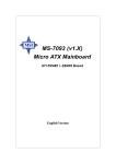
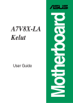
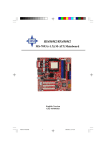
1
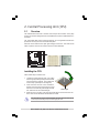
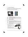
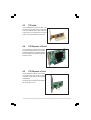
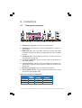
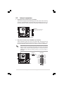
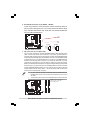
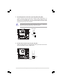
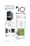
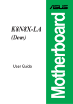
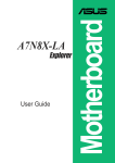
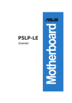
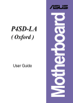
(Amberine/
AmberineM)
User Guide
Motherboard
A8AE-LE
Contents
Checklist
A8AE-LE (Amberine/AmberineM) specifications summary ............ iii
1.
Motherboard layout ............................................................... 1
2.
Central Processing Unit (CPU) .............................................. 2
2.1 Overview ......................................................................... 2
2.2 Installing the CPU ............................................................ 2
3.
System memory .................................................................... 3
3.1 Installing a DIMM ............................................................. 3
4.
Expansion slots ..................................................................... 4
4.1 Standard interrupt assignments ...................................... 4
4.2 IRQ assignments for this motherboard ............................ 4
4.3 PCI slots .......................................................................... 5
4.4 PCI Express x16 slot ....................................................... 5
4.5 PCI Express x1 slot ......................................................... 5
5.
Jumpers ................................................................................. 6
6.
Connectors ............................................................................ 7
6.1 Rear panel connectors .................................................... 7
6.2 Internal connectors .......................................................... 9
Product Name:
Manual Revision:
Release Date:
ii
A8AE-LE (Amberine/AmberineM)
E2098
June 2005
A8AE-LE(Amberine/AmberineM)
specifications summary
CPU
Socket 939 for AMD Athlon™64 FX processor
AMD 64 architecture that enables 32- and 64-bit computing
Chipset
ATI RS482 with ATI SB400
System Bus
2000 MT per second
Memory
4 x 184-pin DDR DIMM sockets for up to 4GB non-ECC 2.6V
Dual Channel memory
Supports PC3200/2700 DDR
Expansion slots
1 x PCI-Express x16 slot
3 x PCI slots
1 x ASUS proprietary PCI expander connector (AmberineM
no Support)
Storage
ATI SB400 Supports :
2 x UltraDMA100/66/33 connectors, PIO Mode 3/4
Supports 4 ATAPI IDE, CD-ROM, CD-R, CD-RW and LS-120
2 x Serial ATA 150 connectors
Onboard Audio
Support AC97 Audio CODEC
RealTek ALC658C 6-channel audio CODEC
Onboard LAN
Realtek RTL810L(D version) 10/100Mbps LAN PHY
Onboard IEEE 1394
VIA VT6307 chipset supports 2 x IEEE1394 ports
Hardware monitoring
Super I/O integrated monitoring of CPU and system fan
rotations and CPU temperature
Rear panel I/O
1 x PS/2 keyboard port
1 x PS/2 mouse port
1 x Parallel port
1 x Serial port
1 x VGA Port
4 x USB 2.0 ports
1 x RJ-45 port
1 x IEEE 1394 port
1 x S-Video (AmberineM no support)
1 x Composite-out (AmberineM no support)
1 x S/PDIF-out
Line In/Line Out/Microphone ports
(continuned on the next page)
iii
iv
Internal I/O
1 x Floppy connector
2 x USB 2.0 connectors for additional 4 USB ports
1 x IEEE 1394 connector for additional 1394 port
1 x CPU and SYSTEM/Chassis FAN connector
1 x 24-pin ATX power connector
1 x 4-pin ATX power connector
1 x Serial port
1 x S/PDIF out connector
1 x CD/AUX audio connectors
1 x Front headphone connector
BIOS features
4Mb LPC EEPROM, AWARD BIOS with Enhanced ACPI,
DMI, Green, PnP Features Plus
Industry Standard
USB 2.0/1.1, PCI 2.2
Power Requirement
ATX power supply (with 24-pin and 4-pin 12V plugs)
Form Factor
ATX form factor: 9.6 in x 9.6 in
1. Motherboard layout
20.8cm (8.2in)
PS/2KBMS
T: Mouse
B: Keyboard
CPU_FAN1
ATX12V1
Super
I/O
Asus
A8000
FLOPPY1
LPC
Flash
ROM
24.5cm (9.6in)
ATXPWR1
BUZZ1
RTL8101L
VIA
VT6307
F_1394
IDE2
PCIEX1
A8AE-LE
IDE1
Top:Line In
Center:Line Out
Below:Mic In
DDR2 DIMMA1 (64 bit,240-pin module)
ATI
RS482
SPDIFOUT1
DDR2 DIMMA1 (64 bit,240-pin module)
USB2.0
Top:
T: USB3 RJ-45
B: USB4
DDR2 DIMMA1 (64 bit,240-pin module)
VGA
Bottom:
T:USB1 Top:
B:USB2 1394
DDR2 DIMMA1 (64 bit,240-pin module)
Socket 939
PARALLEL PORT
CHA_FAN1
CR2032 3V
Lithium Cell
CMOS Power
PCI1
ATI
SB400
PCI2
ALC658
SATA2 SATA1
F_AUDIO1
AUX_IN1
CD_IN1
PC3
PCI45
CLRTC
CLPWD
F_USB1
F_USB2
ASUS A8AE-LE (Amberine/AmberineM) Motherboard
F_PANEL1
1
2. Central Processing Unit (CPU)
2.1
Overview
The motherboard comes with a surface mount 939-pin Zero Insertion Force (ZIF)
socket. The socket is designed for the new AMD Athlon™ 64FX or AMD Athlon 64™
Processor.
The 128-bit-wide data paths of these processors can run applications faster than
processors with only 32-bit or 64-bit wide data paths.
Take note of the marked corner (with gold triangle) on the CPU. This mark should
match a specific corner on the socket to ensure correct installation.
A8AE-LE
A8AE-LE CPU Socket 939
Installing the CPU
Follow these steps to install a CPU.
1. Locate the Socket 939 and open it by pulling
the lever gently sideways away from the socket.
Then lift the lever upwards. The socket lever
must be fully opened (90 to 100 degrees).
2. Insert the CPU with the correct orientation.
Position the CPU above the socket such that
the CPU corner with the gold triangle matches
the socket corner with a small triangle.
Gold triangle
3. When the CPU is in place, push down the socket lever to secure the CPU. The
lever clicks on the side tab to indicate that it is locked.
The CPU fits only in one correct orientation. DO NOT force the CPU into the
socket to prevent bending the pins and damaging the CPU!
2
ASUS A8AE-LE (Amberine/AmberineM) Motherboard
3. System memory
The motherboard comes with four Double Data Rate (DDR) Dual Inline Memory
Module (DIMM) sockets. These sockets support up to 4GB system memory using
184-pin unbuffered non-ECC PC3200/PC2700 DDR DIMMs.
The following figure illustrates the location of the DDR DIMM sockets.
XMM4
XMM3
XMM2
A8AE-LE 184-pin DDR DIMM sockets
XMM1
A8AE-LE
CAUTION: DIMMs are keyed to fit with only one direction. DO NOT force a DIMM
into a socket to avoid damaging the DIMM.
2.2
Installing a DIMM
You may install 64MB, 128MB, 256MB, 512MB, and 1GB DDR DIMMs into the DIMM
sockets using the memory configurations in this section.
Make sure to unplug the power supply before adding or removing DIMMs or other
system components. Failure to do so may cause severe damage to both the
motherboard and the components.
Follow these steps to install a DIMM.
DDR DIMM notch
1. Unlock a DIMM socket by pressing the
retaining clips outward.
2. Align a DIMM on the socket such that
the notch on the DIMM matches the
break on the socket.
3. Firmly insert the DIMM into the socket
until the retaining clips snap back in
place and the DIMM is properly seated.
Unlocked Retaining Clip
ASUS A8AE-LE (Amberine/AmberineM) Motherboard
3
4. Expansion slots
The motherboard has three PCI slots and one Accelerated Graphics Port (AGP) slot.
To install and configure an expansion card:
1. Install an expansion card following the instructions that came with the chassis.
2. Turn on the system and change the necessary BIOS settings, if any.
3. Assign an IRQ to the card. Refer to the tables below.
4. Install the drivers and/or software applications for the expansion card according
to the card documentation.
4.1
*
Standard interrupt assignments
IRQ
Priority
Standard Function
0
1
System Timer
1
2
Keyboard Controller
2
N/A
Programmable Interrupt
3*
11
Communications Port (COM2)
4*
12
Communications Port (COM1)
5*
13
Sound Card (sometimes LPT2)
6
14
Floppy Disk Controller
7*
15
Printer Port (LPT1)
8
3
System CMOS/Real Time Clock
9*
4
ACPI Mode when used
10*
5
IRQ holder for PCI steering
11*
6
IRQ holder for PCI steering
12*
7
PS/2 Compatible Mouse Port
13
8
Numeric Data Processor
14*
9
Primary IDE Channel
15*
10
Secondary IDE Channel
These IRQs are usually available for ISA or PCI devices.
4.2
IRQ assignments for this motherboard
PCI slot 1
PCI slot 2
PCI slot 3
PCI slot 4
PCI slot 5
Onboard 1394 controller
*Onboard USB controller 1
*Onboard LAN
A
INTA#
INTB#
INTC#
INTD#
INTA#
INTE#
INTD#
INTF#
B
INTB#
INTC#
INTD#
INTA#
INTB#
-
C
INTC#
INTD#
INTA#
INTB#
INTC#
-
D
INTD#
INTA#
INTB#
INTC#
INTD#
-
*The onboard USB, LAN and audio IRQs are assigned by the BIOS.
4
ASUS A8AE-LE (Amberine/AmberineM) Motherboard
4.3
PCI slots
This motherboard has three PCI slots. The
PCI slots support cards such as a LAN card,
SCSI card, USB card, and other cards that
comply with PCI specifications. The figure
shows a LAN card installed on a PCI slot.
4.4
PCI Express x16 slot
This motherboard supports PCI Express
x16 graphic cards that comply with the PCI
Express specifications. The following figure
shows a graphics card installed on the PCI
Express x16 slot.
4.5
PCI Express x1 slot
This motherboard supports PCI Express
x1 network card, SCSI cards and other
cards that comply with the PCI Express
specifications.
The figure shows a network card install on
the PCI Express x1 slot.
ASUS A8AE-LE (Amberine/AmberineM) Motherboard
5
5. Jumpers
1. Clear RTC (3-pin CLRTC)
This jumper allows you to clear the Real Time Clock (RTC) RAM in CMOS. You
can clear the CMOS memory of date, time, and system setup parameters by
erasing the CMOS RTC RAM data. The RAM data in CMOS, that include system
setup information, is powered by the onboard button cell battery.
To erase the RTC RAM:
1. Turn OFF the computer and unplug the power cord.
2. Move the jumper cap from pins 2-3 (Default) to pins 1-2 (Clear CMOS).
Keep the cap on pins 1-2 for about 5~10 seconds, then move the cap back
to pins 2-3.
3. Plug the power cord and turn ON the computer.
4. Hold down the <F1> key during the boot process and enter BIOS setup to
re-enter data.
Except when clearing the RTC RAM, never remove the jumper caps on default
position. Removing the cap will cause system boot failure!
CLRTC
A8AE-LE
1 2
2 3
Clear CMOS
A8AE-LE Clear RTC RAM
Normal
(Default)
2. Clear Password (3-pin CLPWD)
This jumper allows you to clear the password in CMOS. To erase the Password
move the jumper cap from pins 2-3 (Default) to pins 1-2 (Clear Password). Keep
the cap on pins 1-2 for about 5~10 seconds, then move the cap back to pins 2-3.
Plug the power cord and turn ON the computer. Hold down the <Del> key during
the boot process and enter BIOS setup to re-enter data.
CLPWD
A8AE-LE
1 2
Normal
(Default)
2 3
Clear Password
A8AE-LE Clear password setting
6
ASUS A8AE-LE (Amberine/AmberineM) Motherboard
6. Connectors
6.1
Rear panel connectors
1
2
3
4
5
6
7
14
13
12
11
10
9
8
1. PS/2 mouse port (green). This port is for a PS/2 mouse.
2. Parallel port. This 25-pin port connects a parallel printer, a scanner, or
other devices.
3. IEEE 1394a port. This 6-pin IEEE 1394a port provides high-speed
connectivity for audio/video devices, storage peripherals, PCs, or portable
devices.
4. LAN (RJ-45) port. This port allows connection to a Local Area Network
(LAN) through a network hub.
5. Line In port (light blue). This port connects a tape, CD, DVD player or
other audio sources.
6. Line Out port (lime). This port connects a headphone or a speaker. In 4channel and 6-channel mode, the function of this port becomes Front
Speaker Out.
7. Microphone port (pink). This port connects a microphone.
8. Coaxial S/PDIF Out port. This port connects an external audio output
device via a coaxial S/PDIF cable.
Audio 2, 4, or 6-channel configuration
Headset/
2-channel
4-channel
Line In
Line In
Line In
Lime
Line Out
Front Speaker Out
Front Speaker Out
Pink
Mic In
Mic In
Center/Subwoofer
Light Blue
6-channel
ASUS A8AE-LE (Amberine/AmberineM) Motherboard
7
9. USB 2.0 ports 3 and 4. These two 4-pin Universal Serial Bus (USB)
ports are available for connecting USB 2.0 devices.
10. USB 2.0 ports 1 and 2. These two 4-pin Universal Serial Bus (USB)
ports are available for connecting USB 2.0 devices.
11. VGA Graphic Adapter port. This 15-pin port is for a VGA monitor or
other VGA-compatible devices.
12. S-Video Out port. This port connects an external Video output device
via a S-Video cable.
13. Composite Out port . This port connects an external audio output device
via a Composite cable.
14. PS/2 keyboard port (purple). This port is for a PS/2 keyboard.
8
ASUS A8AE-LE (Amberine/AmberineM) Motherboard
6.2
Internal connectors
1. Floppy disk drive connector (34-1 pin FLOPPY)
This connector supports the provided floppy drive ribbon cable. After connecting
one end to the motherboard, connect the other end to the floppy drive. (Pin 5 is
removed to prevent incorrect insertion when using ribbon cables with pin 5 plug).
FLOPPY1
NOTE: Orient the red markings on
the floppy ribbon cable to PIN 1.
A8AE-LE
PIN 1
A8AE-LE Floppy disk drive connector
2. ATX power connectors (24-pin ATXPWR1, 4-pin ATX12V1)
These connectors connect to an ATX 12V power supply. The plugs from the
power supply are designed to fit these connectors in only one orientation. Find
the proper orientation and push down firmly until the connectors completely fit.
Make sure that your ATX 12V power supply can provide 8A on the +12V lead and
at least 1A on the +5-volt standby lead (+5VSB). The minimum recommended
wattage is 230W, or 300W for a fully configured system. The system may become
unstable and may experience difficulty powering up if the power supply is
inadequate.
ATX12V1
GND
+12V DC
A8AE-LE
A8AE-LE ATX power connectors
ATXPWR1
GND
+12V DC +3 Volts
+12 Volts
+12 Volts
+5V Standby
Power OK
Ground
+5 Volts
Ground
+5 Volts
Ground
+3 Volts
+3 Volts
Ground
+5 Volts
+5 Volts
+5 Volts
-5 Volts
Ground
Ground
Ground
PSON#
Ground
-12 Volts
+3 Volts
ASUS A8AE-LE (Amberine/AmberineM) Motherboard
9
3. Serial ATA connectors (7-pin SATA1, SATA0)
These next generation connectors support the thin Serial ATA cables for
primary internal storage devices. The current Serial ATA interface allows
up to 150 MB/s data transfer rate, faster than the standard parallel ATA
with 133 MB/s (UltraDMA133).
A8AE-LE
SATA1
A8AE-LE SATA connectors
SATA2
GND
RSATA_TXP2
RSATA_TXN2
GND
RSATA_RXP2
RSATA_RXN2
GND
GND
RSATA_TXP1
RSATA_TXN1
GND
RSATA_RXP1
RSATA_RXN1
GND
4. IDE connectors (40-1 pin IDE1, IDE2)
This connector supports the provided UltraDMA100/66/33 IDE hard disk ribbon
cable. Connect the cable’s blue connector to the primary (recommended) or
secondary IDE connector, then connect the gray connector to the UltraDMA100/66/
33 slave device (hard disk drive) and the black connector to the UltraDMA100/66/
33 master device. It is recommended that you connect non-UltraDMA100/66/33
devices to the secondary IDE connector. If you install two hard disks, you must
configure the second drive as a slave device by setting its jumper accordingly.
Refer to the hard disk documentation for the jumper settings. BIOS supports specific
device bootup. If you have more than two UltraDMA100/66/33 devices, purchase
another UltraDMA100/66/33 cable. You may configure two hard disks to be both
master devices with two ribbon cables – one for the primary IDE connector and
another for the secondary IDE connector.
1.
Pin 20 on each IDE connector is removed to match the covered hole on the
UltraDMA cable connector. This prevents incorrect orientation when you connect
the cables.
2.
The hole near the blue connector on the UltraDMA100/66/33 cable is intentional.
PIN 1
IDE1
A8AE-LE
IDE2
NOTE: Orient the red markings
(usually zigzag) on the IDE
ribbon cable to PIN 1.
PIN 1
A8AE-LE IDE connectors
10
ASUS A8AE-LE (Amberine/AmberineM) Motherboard
5. CPU and System Fan Connectors (3-pin CPU_FAN1, CHA_FAN1)
The fan connectors support cooling fans of 350mA~740mA (8.88W max.) or a
total of 1A~2.22A (26.64W max.) at +12V. Connect the fan cables to the fan
connectors on the motherboard, making sure that the black wire of each cable
matches the ground pin of the connector.
Do not forget to connect the fan cables to the fan connectors. Lack of sufficient air
flow within the system may damage the motherboard components. These are not
jumpers! DO NOT place jumper caps on the fan connectors!
GND
+12V
Rotation
CPU_FAN1
CHA_FAN1
A8AE-LE
Rotation
+12V
GND
A8AE-LE Fan connectors
6. Internal audio connectors (4-pin CD_IN1, AUX_IN1)
A8AE-LE
Left Audio Channel
Ground
Ground
Right Audio Channel
These connectors allow you to receive stereo audio input from sound sources
such as a CD-ROM, TV tuner, or MPEG card.
AUX_IN1
CD_IN1
A8AE-LE Internal audio connectors
ASUS A8AE-LE (Amberine/AmberineM) Motherboard
11
7. USB headers (10-1 pin F_USB1,F_USB2)
If the USB ports on the rear panel are inadequate, a USB header is available for
additional USB ports. The USB header complies with USB 2.0 specification that
supports up to 480 Mbps connection speed. This speed advantage over the
conventional 12 Mbps on USB 1.1 allows faster Internet connection, interactive
gaming, and simultaneous running of high-speed peripherals. You may connect
a USB module to the USB header.
The USB module is purchased separately.
USB+5V
USB_P6USB_P6+
GND
NC
USB+5V
USB_P5USB_P5+
GND
A8AE-LE USB 2.0 connectors
USB+5V
USB_P5USB_P5+
GND
A8AE-LE
F_USB2
USB+5V
USB_P6USB_P6+
GND
NC
F_USB1
8. IEEE 1394 connector (10-1 pin F_1394)
This connector is for a 10-to-6-pin 1394 serial connector cable that connects to a
1394 module. Attach the 10-1 pin cable plug to this connector, and the 6-pin
cable plug to the 1394 module. You may also connect a 1394-compliant internal
hard disk to this connector.
TPA1GND
TPB1+12V
GND
NEVER connect a USB cable to any of the IEEE 1394 connectors. Doing so will
damage the motherboard!
A8AE-LE
A8AE-LE IEEE 1394 connector
12
1
TPA1+
GND
TPB1+
+12V
F_1394
ASUS A8AE-LE (Amberine/AmberineM) Motherboard
9. Front panel audio connector (10-1 pin F_AUDIO1)
This is an interface for the Intel front panel audio cable that allow convenient
connection and control of audio devices.
AUD_GND
AUD_VCC
AUD_RET_R
AUD_VCC
AUD_RET_L
By default, the pins labeled LINE_OUT_R/BLINE_OUT_R and the pins
LINE_OUT_L/BLINE_OUT_L are shorted with jumper caps. Remove the caps
only when you are connecting the front panel audio cable.
F_AUDIO1
A8AE-LE Front audio connector
1
AUD_MIC1
AUD_MIC2
AUD_FPOUT_R
AUD_MIC_JD
AUD_FPOUT_L
A8AE-LE
ASUS A8AE-LE (Amberine/AmberineM) Motherboard
13
10. System panel connector (10-pin F_PANEL1)
This connector accommodates several system front panel functions.
PLED+
PLEDPWR
GND
PWR LED PWR BTN
F_PANEL1
HDLED+
HDLEDGround
Reset
NC
A8AE-LE
HD LED RESET
A8AE-LE System panel connector
•
System Power LED Lead (2-pin PWR LED)
This 3-1 pin connector connects to the system power LED. The LED lights up
when you turn on the system power, and blinks when the system is in sleep
mode.
•
Hard Disk Activity LED Lead (2-pin HD LED)
This 2-pin connector is for the HDD LED cable. The read or write activities of the
device connected to the any of IDE connectors cause the IDE LED to light up.
•
ATX Power Switch / Soft-Off Switch Lead (2-pin PWR BTN)
This connector connects a switch that controls the system power. Pressing the
power switch turns the system between ON and SLEEP, or ON and SOFT OFF,
depending on the BIOS or OS settings. Pressing the power switch while in the
ON mode for more than 4 seconds turns the system OFF.
•
Reset Switch Lead (2-pin RESET)
This 2-pin connector connects to the case-mounted reset switch for rebooting
the system without turning off the system power.
14
ASUS A8AE-LE (Amberine/AmberineM) Motherboard