1
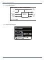
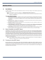
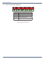
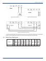
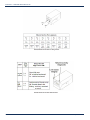
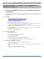
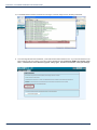
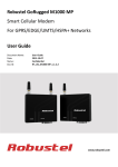
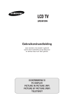
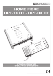
CCAP™
Compliant
MP3 Active/Passive Chassis
Installation & Operation Manual
1.2 GHz
Although every effort has been taken to ensure the accuracy of this document it may be necessary, without notice, to make amendments or correct omissions.
Specifications subject to change without notice.
MAXNET ® II is a registered trademark of ATX in the United States and/or other countries. Products or features contained herein may be covered by one or more U.S. or foreign
patents. Other non-ATX product and company names in this manual are the property of their respective companies.
TABLE OF CONTENTS
Page
1.
PRODUCT DESCRIPTION......................................................................................................................... 1-1
1.1. Functional Diagrams.......................................................................................................................... 1-2
1.2. Technical Specifications..................................................................................................................... 1-2
2.
INSTALLATION.......................................................................................................................................... 2-1
2.1. Module Installation Into the MP3 Chassis.......................................................................................... 2-1
2.2. Powering the Active MP3 Chassis...................................................................................................... 2-1
2.3. Remote Chassis Power Applications.................................................................................................. 2-2
2.4. Module Power Requirements............................................................................................................. 2-3
3.
HARDWARE NETWORK SET-UP.............................................................................................................. 3-1
3.1. LED Indicators.................................................................................................................................... 3-1
3.2. Ethernet Port...................................................................................................................................... 3-1
4.
STATUS MONITORING.............................................................................................................................. 4-1
4.1. Chassis Interface Options.................................................................................................................. 4-1
4.2. Software Network Set-up................................................................................................................... 4-1
4.3. Web Interface..................................................................................................................................... 4-1
4.4. Module Replacement......................................................................................................................... 4-2
4.5. Factory Reset..................................................................................................................................... 4-2
4.6. SNMP Parameters.............................................................................................................................. 4-3
4.7. Default Alarm Thresholds................................................................................................................... 4-6
4.8. SNMP MIBs Required........................................................................................................................ 4-7
5.
SETTING UP A MAXNET® II CHASSIS TO USE A MEINBERG NTP SERVER LOCAL HOST PC.......... 5-1
5.1. Installation.......................................................................................................................................... 5-1
5.2. Starting the NTP Server..................................................................................................................... 5-1
5.3. Setting up the MAXNET® II Chassis................................................................................................... 5-1
6.
FTP SERVER FIRMWARE LOAD INSTRUCTIONS.................................................................................. 6-1
7.
MAINTENANCE & TROUBLESHOOTING................................................................................................. 7-1
7.1. Maintenance....................................................................................................................................... 7-1
7.2. Troubleshooting.................................................................................................................................. 7-1
8.
SERVICE & SUPPORT............................................................................................................................... 8-1
8.1. Contact ATX Networks........................................................................................................................ 8-1
8.2. Warranty Information.......................................................................................................................... 8-1
8.3. Safety................................................................................................................................................. 8-1
MAXNET® II – MP3 Active / Passive Chassis – Installation & Operation Manual
i
Index of Figures and Tables
Figures
#1 Active Chassis Functional Diagram..............................................................1-2
#2 Remote Powering.........................................................................................2-3
#3 Redundant Powering....................................................................................2-3
#4 Redundant Remote Powering......................................................................2-3
Tables
#1 Ordering Information.....................................................................................1-1
#2 Active Chassis Technical Specifications.......................................................1-2
#3 Terminal Block Pin Assignments...................................................................2-2
#4 Ethernet Interface Pin Assignments.............................................................3-2
#5 Ethernet Interface LED Indicators................................................................3-2
#6 Administration Level SNMP Parameters......................................................4-3
#7 Common Module SNMP Parameters...........................................................4-3
#8 RF and Optical Switch SNMP Parameters...................................................4-4
#9 MPTX Laser SNMP Parameters...................................................................4-5
#10 Misc. SNMP Parameters..............................................................................4-5
#11 General IETF MIBs Required - All Modules..................................................4-7
#12 General SCTE HMS MIBs Required - All Modules.......................................4-7
#13 Module-Specific SCTE HMS MIB’s Required...............................................4-7
ii
MAXNET® II – MP3 Active / Passive Chassis – Installation & Operation Manual
CHAPTER 1: PRODUCT DESCRIPTION
PRODUCT DESCRIPTION
1.
Product Description
The MP3 chassis is a 3RU design that comes in both a passive and active configuration. Both configurations include options
for dual cable management bars and a large cable management tray as well as user configurable horizontal and vertical
cable management systems. The MP3 active chassis also include a fiber management tray that can be configured into two
positions.
The passive and active chassis’ can accommodate up to 24 single-width passive modules (DC Logic A/B RF Switch; 2,
4, 8, dual 4-way and triple 2-way splitters\combiners; DC & triple DCs) or up to 12 dual-width modules (16-way splitter\
combiners).
The active chassis can accommodate all the modules that a passive chassis can, but also up to 12 dual-width active modules
(amplifier, power supply, optical receiver\transmitter, RF Switch).
The active chassis comes with a +24 VDC power interface backplane/rail and a removable communications module that
draws power from the rail. This communications module can be removed without affecting the operation of the modules in the
chassis by removing the two Phillips screws on either side that fasten it to the chassis. All active modules are hot-swappable.
Power is supplied to the backplane by installing an MPAC or MPDC power supply into one of the chassis slots or by remotely
powering the chassis from an external 24 VDC supply. The MP3 active chassis is equipped with an HMS compliant SNMP
management system. An RJ-45 port is used for both set-up and status monitoring. No custom software is required.
Please refer to the web page for up-to-date specifications – www.atxnetworks.com
Part Number
Description
MP1
1RU Passive Chassis with Cable Management Bar
MP3B
3RU Passive Chassis with Dual Cable Management Cable Bars
MP3H
3RU Passive Chassis with Configurable Horizontal Channel Cable Management
MP3V
3RU Passive Chassis with Configurable Vertical Channel Cable Management
MP3T
3RU Passive Chassis with Large Cable Management Tray
MP3R
3RU Passive Reverse Chassis
MP3BA
3RU Active Chassis with Dual Cable Management Cable Bars
MP3RA
3RU Active Reverse Chassis
MP3HA
3RU Active Chassis with Configurable Horizontal Channel Cable Management
MP3VA
3RU Active Chassis with Configurable Vertical Channel Cable Management
MP3TA
3RU Active Chassis with Large Cable Management Tray
MPRB
Round Cable Management Steel Bar
MPBAR
Flat Cable Management Steel Bar
MPFT
Fiber Management Tray (includes 12 push fit plastic fiber guides) for 3RU Chassis
MPLT
Large Cable Management Tray (includes clips)
MP3FA
3RU Active Chassis for F Connector Optics Platform (includes rear rails for patch
panels & front fiber tray)
MP3FA-COM
Table #1: Ordering
Information
Replacement Communication
Module for
MP3FA
MP3FA-T
Replacement Fiber Management Tray for MP3FA
MPHKIT
Configurable Horizontal Channel Cable Management Kit
(See http://www.atxnetworks.com/pdf/ANW0614_MNII_ChassisCableOptns.pdf
for photos of various options)
__________________________________________________
1
Provided that the chassis is not being solely powered via the terminal block on the comm module, there would simply be no alarms and no remote
adjustment of parameters. The modules would continue to run with the last set values.
2
It is not recommended to hot swap a power supply module into a full chassis if there is no other power supply present. The current surge to supply a
full rack of active modules would be stressful on the electrical contacts during mating and may reduce the lifespan of the chassis and power supply. It
is recommended that you install the power supply first, then apply AC or DC input to the power supply connector.
MAXNET® II – MP3 Active / Passive Chassis – Installation & Operation Manual
1-1
CHAPTER 1: PRODUCT DESCRIPTION
1.1.
Functional Diagrams
Active Chassis: DC Power & Communications
24 VDC A
+24 V
CHASSIS
BUS
24 VDC B
PWR
CHASSIS MONITOR,
CONTROL &
COMMUNICATIONS
CHASSIS COMM.
(TO ACTIVE
MODULES)
SNMP (HMS)/
ETHERNET
COMM
INT COMM
RELAY
N.O.
CHASSIS
ALARM
INPUT VOLTAGE: 24 VOLTS DC
INPUT CURRENT: 8.0 AMPS MAX
Figure #1: Active Chassis Functional Diagram
1.2.
Technical Specifications
Table #2: Active Chassis Technical Specifications
1-2
MAXNET® II – MP3 Active / Passive Chassis – Installation & Operation Manual
CHAPTER 2: INSTALLATION
INSTALLATION
2.
Installation
The MP3 is a 3RU chassis and comes pre-assembled and ready to mount to any existing 19” rack cabinet hub system using
10/32” rack screws.
NOTE: This equipment is intended for installation in a RESTRICTED ACCESS LOCATION only.
NOTE: Not for use in a computer room as defined in the Standard for Protection of Electronic Computer/Data Processing
Equipment, ANSI/NFPA 75.
Rack Mounting Precautions
2.1.
a)
Elevated Operating Ambient - If installed in a closed or multi-unit rack assembly, the operating ambient temperature
of the rack environment may be greater than room ambient. Therefore, consideration should be given to installing
the equipment in an environment compatible with the maximum ambient temperature (35ºC) specified by the
manufacturer.
b)
Reduced Air Flow - Installation of the equipment in a rack should be such that the amount of airflow required for
safe operation of the equipment is not compromised.
c)
Mechanical Loading - Mounting of the equipment in the rack should be such that a hazardous condition is not
achieved due to uneven mechanical loading.
d)
Circuit Overloading - Consideration should be given to the connection of the equipment to the supply circuit
and the effect that overloading of the circuits might have on overcurrent protection and supply wiring. Appropriate
consideration of equipment nameplate ratings should be used when addressing this concern.
e)
Reliable Earthing - Reliable earthing of rack-mounted equipment should be maintained. Particular attention should
be given to supply connections other than direct connections to the branch circuit (e.g. use of power strips).”
Module Installation Into the MP3 Chassis
All MAXNET II active and passive chassis have 24 grooves that act as guide slots for the active and passive modules.
Passive modules and the DC Logic Switch can be inserted into any of the 24 slots. Active modules must be inserted into the
odd number slots indicated by the white markers on the bottom rail of the chassis. These odd numbered slots are the
only slots that will allow an active module to be connected to the active chassis backplane to receive power and allow monitor
and control of the module. To insert a module, align the module guide rails to the chassis guide slots and then gently slide
the module into a locked position (the module should be flush against the top and bottom rail of the chassis). No mounting
hardware is required. To remove a module, grab the front handle on the module and gently lift and pull back the module until
it is clear of the chassis guide rails.
NOTE: When installing the MPAC or MPDC Power Supply, the GND bonding terminal #1 on the back of the MPAC or
MPDC Power Supply shall be connected to the chassis ground lug.
2.2.
Powering the Active MP3 Chassis
The MP3 active chassis can be powered by power supply modules (MPAC-110, MPAC-220 or MPDC) installed in one of the
slots of the chassis, or by connecting power directly to one or both of the terminal block inputs on the rear of the chassis. Both
connections are not necessary unless redundancy is required. If the source of 24 VDC is not an MPXX power supply, the line
should be fused at a minimum with a 10 Amp slo-blo fuse. A disconnect device is required between the 24 VDC supply and
the Chassis remote power terminals.
MAXNET® II – MP3 Active / Passive Chassis – Installation & Operation Manual
2-1
CHAPTER 2: INSTALLATION
2.3.
Remote Chassis Power Applications
RLY
NO
RLY
COM
NAME
+ 24V A
COM
+24V B
RLY COM
RLY NO
+24V
B
COM
+24V
A
DESCRIPTION
+24 VDC input A
Ground
+24 VDC input B
Common Relay Contact
Normally Open Relay Contact (fault
condition if open circuit to RLY COM)
* recommended minimum of #12 gauge wire rated for up to 10A
Table #3: Terminal Block Pin Assignments
2-2
MAXNET® II – MP3 Active / Passive Chassis – Installation & Operation Manual
CHAPTER 2: INSTALLATION
Figure #2: Remote Powering
Figure #3: Redundant Powering
Figure #4: Redundant Remote Powering
* In any of the examples above, be sure to refer to the next section for module power requirements. In any redundant
scenario, if a power supply fails, the load on any remaining power supply must not exceed 8 amps.
Module
MPRX-8 /
MPRX-16
MPRX2-8
MPRXRR-16 /
MPRXRR-8
MPRX-DC /
MPRX2-DC
MPRX2-DC
MPRFA/B
QMP200
QMP1000
(< 22 dB Gain)
QMP1000
(> 22 dB Gain)
Module Power Requirements
MPAC / MPDC
2.4.
Max Current (A)
8
0.29
0.52
0.46
0.29
0.52
0.03
0.14
0.47
0.52
MAXNET® II – MP3 Active / Passive Chassis – Installation & Operation Manual
2-3
CHAPTER 2: INSTALLATION
This page left intentionally blank.
2-4
MAXNET® II – MP3 Active / Passive Chassis – Installation & Operation Manual
CHAPTER 3: HARDWARE NETWORK SET-UP
HARDWARE NETWORK SET-UP
3.
Hardware Network Set-up
The MP3 active chassis can be easily connected to an existing network through the use of a patch cable connected between
the network port on the rear of the chassis and any switch or router. For a connection directly to a PC or laptop, use a
crossover cable. This product has been verified to work on Windows XP/2000 and Linux operating systems.
3.1.
LED Indicators
Reset
Button
Network Activity
LED Status
Link Status
LED
Status Monitoring
Activity LED
Chassis Power
LED Status
There are four LED’s visible at the rear of the chassis. Two small square LEDs on the RJ45 port itself (see the next section
for details on these), a large yellow ‘COM’ and green ‘24V’ LED.
The ‘24V’ LED indicates the presence of power to the chassis and comm module, it should always be solid and bright.
The ‘COM’ LED will be solid during the boot cycle of the device but should start blinking after approximately 2 minutes. It must
always be blinking during regular operation to indicate the monitoring software is running.
3.2.
Ethernet Port
The RJ45 Ethernet port visible at the rear of the chassis is actually the DC-ME-01T-C embedded device server, manufactured
by Digi International and loaded with custom ATX firmware. The following figures and text were taken directly from the
“Digi Connect ME & Digi Connect Wi-ME Hardware Reference”. For more information, please go to www.digi.com.
The Ethernet connector is an 8-wire RJ-45 jack that meets the ISO 8877 requirements for 10/100BASE-T. See the following
figure and table for pin orientation and pin assignments.
The yellow LED indicates whether a valid network connection is present. It should be solid. Otherwise, check the network
cable or the piece of hardware that has been connected to the network cable (switch, router or PC’s network card).
The green LED indicates network activity. It will be solid during any boot process (approx 2 min) and then blink if there is any
network traffic. If it remains solid, this may be indicative of corrupt hardware – contact ATX Networks.
MAXNET® II – MP3 Active / Passive Chassis – Installation & Operation Manual
3-1
CHAPTER 3: HARDWARE NETWORK SET-UP
Table #4: Ethernet Interface Pin Assignments
Table #5: Ethernet Interface LED Indicators
3-2
MAXNET® II – MP3 Active / Passive Chassis – Installation & Operation Manual
CHAPTER 4: STATUS MONITORING
STATUS MONITORING
4.
Status Monitoring
4.1.
Chassis Interface Options
The Active MAXNET II product line can be monitored and controlled in either of two ways:
4.2.
a)
A free, web-based interface. This comes pre-installed on every chassis and provides a user friendly method of
configuring the administrative set-up and all monitoring and control. It is based on SNMP, but requires little knowledge
of SNMP. Any Internet browser, such as Internet Explorer, is all the software that is required.
b)
Any third-party SNMP Management software (eg. www.castlerock.com, www.ndt-inc.com/SNMP/MIBrowser.html )
may be purchased separately. These suites tend to be expensive and not as user friendly as the web interface. The
web interface is also still required for administrative set-up. The 3rd party interface is recommended only for systems
that have an existing SNMP architecture. All MIBs (Management Information Bases) are freely downloadable from
the SCTE (www.scte.org/standards). ATX was able to support all modules using the SCTE standard HMS MIBs, so
no custom MIBs are required.
Software Network Set-up
a)
Recommended: Connect the chassis to a PC/laptop directly with a cross-over network cable.
Alternative: Connect the chassis to a switch or router using a patch network cable.
4.3.
b)
Enter the IP address of the chassis as the URL in a web browser. By default (factory reset), this will be 192.168.0.1.
If the device does not respond, see Troubleshooting section at the end of this document.
c)
The login page should appear. Login as administrator (default password for all levels is the lower case name of the
level, i.e. Observer password is observer).
d)
The configuration settings page should appear. It is important to either use DHCP or (preferably) assign a unique
IP address to each MP3 chassis that will be on the same subnet as your DHCP server assigns addresses. “Same
Subnet” refers to an IP address that has the same first three octets, but a unique fourth octet e.g. 192.168.0.1 and
192.168.0.2 are on the same subnet.
e)
Obtain a list of IP addresses from your IT department to use for your chassis’ and assign them one by one. If DHCP
is chosen, then this is not required, but you may have trouble finding out what IP address the DHCP server assigned
to each chassis, and it may change during a reboot of the chassis or DHCP server, so it is not recommended unless
the DHCP server is set to assign static IP addresses to the unique MAC addresses of each chassis installed.
f)
There are several other options that can be set at this time, see Table 6 for a list.
g)
Select ‘save changes’ and reboot. The device will take approximately 90 seconds before it is responsive again.
Remember that your PC/laptop must be set to the same subnet to ‘see’ it, so if you just assigned an IP address
other than 192.168.0.x, then you will need to change your PC’s IP again. It is recommended you change all chassis
IP addresses before reverting your PC back to DHCP.
Web Interface
The MAXNET II chassis uses an integrated web page to supplement the SNMP management. All configuration of the chassis
(static IP address, trap/email recipients, firmware upgrades, etc) must be done through the web page. Simply use any web
browser (Internet Explorer, Firefox, etc) and enter the IP address of the chassis as the URL. Login as administrator to modify
configuration and have full read/write access to monitor and control modules. Login as Operator to have full read/write access
or login as observer to have read-only access. There is only one password per login level.
MAXNET® II – MP3 Active / Passive Chassis – Installation & Operation Manual
4-1
CHAPTER 4: STATUS MONITORING
4.4.
Module Replacement
In order to facilitate the replacement of any MAXNET II module, the software set-up information of the module such as HI
and LO alarm thresholds and alias are stored in the chassis itself and not the module. If any module is removed the chassis
and the same module or another of the same type is inserted into that slot of the chassis, then this configuration data will be
maintained.
This is not true for switch parameters though. In order to meet switch time specifications at the module, this information
is stored within the module itself and therefore will travel with it wherever it is installed next. These parameters include
hysteresis, switch threshold, wait to restore time, etc.
4.5.
Factory Reset
A factory reset will restore the chassis to the state which it left the ATX production facility.
4.5.1. Parameters That Will be Changed
IP address = 192.168.0.1
NetMask = 255.255.255.0
Gateway = 192.168.0.254
Passwords set to same text (but all lower case) as the login level. e.g. Operator password is operator.
All analogue and discrete alarm thresholds of modules will be reset to default values (except RF and optical switch data as
mentioned in the Module Replacement section above).
Alarm log will be cleared.
4.5.2. Purpose
Common reasons for requiring a factory reset are:
a)
The chassis is unresponsive, or the IP address is not known
b)
The Administrator password has been forgotten
c)
The yellow COMM LED does not blink after the 2 minute boot cycle, even after a power cycle or press of the RESET
button
4.5.3. Method
If you are sure you want to factory reset, hold down the RESET button near the RJ45 port for at least 10 seconds. The yellow
COMM LED will be solid-on during this time, and once it turns off you can release the button and the reboot process will
begin.
4-2
MAXNET® II – MP3 Active / Passive Chassis – Installation & Operation Manual
CHAPTER 4: STATUS MONITORING
4.6.
SNMP Parameters
Display Name
Description
Hostname/ Domain Name
Optional fields.
IP Address, Subnet Mask,
Default Gateway
Define the static IP address of the chassis. This address is maintained during power cycles and firmware upgrades. A factory
reset will revert the IP back to 192.168.0.1
DNS Servers
Enter the domain name server to be able to enter textual URLs instead of only IP
addresses.
This affects how you can enter data in some fields below such as NTP server and SMTP server.
NTP Server
Network Time Server (e.g. time.windows.com). If there is no network time server available leave this blank. All times are then
counting from midnight, Jan 1st, 1970 as the start-up time (this is an internet standard).
Time Zone
Only used if NTP server used. Adds local time zone offset to UTC time. e.g. for
Eastern Standard Time Zone, enter ‘UTC+5:0’.
Read-write Community Name
SNMP required variable.
Read-only Community Name
SNMP required variable.
Default Trap Community Name
SNMP required variable.
Trap Recipient List
List up to 10 IP addresses that are to receive SNMP traps
(requires an SNMP trap receiver to interpret these alarm messages).
System Name, Location, Contact
Optional SNMP fields. User can store information about this particular chassis for reference later.
SMTP Server
Outgoing mail server.
If you do not specify a DNS server above, then the server must be entered as an IP address.
Email Recipient List
List up to 5 email addresses that are to receive an email form of the traps.
SMTP Username, Password
If authentication required (ask your IT department), you must enter an email user name and password.
Table #6: Administration Level SNMP Parameters
Display Name
Description
HMS MIB Variable
Read Write /
Read Only
Model
ATX model number (note, in empty slots you can enter
passive, dual-passive, or empty to populate the overview
page with passive picture placeholders).
entPhysicalModelName
RO
Description
Description of the module.
entPhysicalDescr
RO
Name
Indicates the slot of the chassis the module is in.
entPhysicalName
RO
Alias
Optional user defined field - added to fifth variable binding
of traps and emails
e.g. set this to “Node 69” for a given Receiver and any
entPhysicalAlias
alarms generated by this receiver will have “Node 69” in the
description. Otherwise, it would only contain the IP
address of the chassis, the Model and Name (slot number).
RW
Manufacturer
ATX
entPhysicalMfgName
RO
Asset I.D
Optional user settable field (suggestions: enter in a custom
serial number or purchase order # for tracking).
entPhysicalAssetID
RW
Serial No
Module’s serial number.
entPhysicalSerialNum
RO
Hardware Rev
Hardware rev of module.
entPhysicalHardwareRev
RO
Firmware Rev
Firmware rev of module.
entPhysicalFirmwareRev
RO
Temperature [C]
Module’s current heatsink temperature.
heCommonTemperature
RO
Alarm Detection Control
detectionEnabled: normal operation, with active alarms
detectionDisabled: used to temporarily disable alarms/traps
from this module
detectionEnabledandRegenerate: enter detectionEnabled
state while regenerating all alarm table entries
heCommonAlarmDetectionControl RW
Fan Unit Status
Alarm status of the fan.
heFanUnitAlarm
RO
Voltage In [Volt]
Measured voltage supplied to the module from the chassis
(nominally 24V).
hePsUnitVoltageIN
RO
Current In [mA]
Current taken from the 24V rail by the module.
hePsUnitCurrentIN
RO
Power In [Watts]
P.S. Voltage * P.S. Current
hePsUnitPowerIN
RO
Table #7: Common Module SNMP Parameters
MAXNET® II – MP3 Active / Passive Chassis – Installation & Operation Manual
4-3
CHAPTER 4: STATUS MONITORING
Display Name
Description
HMS MIB Variable
Read Write /
Read Only
Switch Mode
Automatic : switching based on threshold
Manual : switch forced to Default position
heRFSwitchMode /
heOpSwitchMode
RW
Switch Control
Default position of switch (PathA or PathB only).
heRFSwitchControl /
heOpSwitchControl
RW
Switch Revert Enable
On: switch will revert back to default position if power
returns to it (also, must be in automatic mode and
hysteresis accounted for).
heRFSwitchRevertEnable /
heOpSwitchRevertEnable
RW
Switch State
Current position of the switch (PathA or PathB only).
heRFSwitchState / heOpSwitchState
RO
Switch Fail-Over Status
Fault if RF Sw Control not equal to RF/Opt Sw State.
heRFSwitchFailoverStatus /
heOpSwitchFailoverStatus
RO
Switch Both Input Status
Fault if either switch input is below RF/Opt Sw Input
Power Threshold.
heRFSwitchBothInputStatus /
heOpSwitchBothInputStatus
RO
Switch Hysteresis [dB]
Only values >= 0 are acceptable. e.g. If 2 dB , switch
will occur if power falls below RF Sw Input Power
Threshold, but does not return until power exceeds RF heRFSwitchHysteresis /
Sw Input Power Threshold + 2 dB (*must also be in
heOpSwitchHysteresis
automatic mode, revert-enable on and wait to restore
time expired).
RW
Switch Wait to Restore
Time [sec]
Time-based hysteresis. Same principle as above, but
time delayed switching if default path power returns.
heRFSwitchWaitToRestoreTime /
heOpSwitchWaitToRestoreTime
RW
Switch Input Level
Measured input level of switch.
heRFSwitchInputRFLevel /
heOpSwitchInputRFLevel
RO
Switch Input Power
Threshold [dBm]
User defined switch threshold.
heRFSwitchSetInputPowerThreshold /
RW
heOpSwitchSetInputPowerThreshold
Switch Output Description Description of the output.
heRFSwitchOutputDescription /
heOpSwitchOutputDescription
RO
Switch Wavelength
Optional, user-settable integer to store the wavelength
of operation. This value has no effect on the operation
of the device.
heOpSwitchSelectWavelength
RW
Switch Input Status
If RF/Opt Input power is below the input power
threshold, then this discrete variable will be in fault,
generating an alarm condition.
heRFSwitchInputStatus /
heOpSwitchInputStatus
RO
Switch Input Description
Identifies inputs as either path A or path B.
heRFSwitchInputDescription /
heOpSwitchInputDescription
RO
Table #8: RF and Optical Switch SNMP Parameters
4-4
MAXNET® II – MP3 Active / Passive Chassis – Installation & Operation Manual
CHAPTER 4: STATUS MONITORING
Display Name
Description
HMS MIB Variable
Read Write /
Read Only
Input AGC Mode
Automatic Gain Control mode, if set to on then the broadcast
digital attenuator is automatically adjusted to provide RF power
levels at laser input for optimum OMI.
heOpTxInputAGCMode
RW
Input Modulation Mode
Either CW or modulated. This variable affects the calibration of
the RF power detector. There is approx a 2 dB difference seen
by the power detector if a CW or modulated carrier of the same
power is applied.
heOpTxInputModulationMode
RW
Input Attenuation, BC
Input Attenuation, NC
Input digital attenuators. See MPTX functional diagrams to see
location of the BC (Broadcast) and NC (Narrowcast)
attenuators. 0-15 dB in 0.5 dB steps.
heOpTxInputRFPadLevel
RW
Laser Temperature
Laser Temperature.
heOpTxLaserTemp
RO
Laser Bias Current
Laser Bias Current.
heOpTxLaserBiasCurrent
RO
Laser Output Power
If a 10dBm laser is ordered, this variable will be close to 10 dB,
with some variation as individual lasers are tuned for optimum
OMI.
heOpTxLaserOutputPower
RO
Laser TEC Current
Thermo-Electric cooler current.
heOpTxLaserTECCurrent
RO
Laser Type
Typically “Cooled DFB”.
heOpTxLaserType
RO
Laser Wavelength
Factory set wavelength of laser.
heOpTxLaserWavelength
RO
Laser Output Status
A read-only field to indicate what Laser On/Off control is set to.
heOpTxLaserOutputStatus
RO
Laser On/Off Control
A writable field. Laser is muted if set to off.
heOpTxLaserOnOffControl
RW
Table #9: MPTX Laser SNMP Parameters
Display Name
OptRx Input Power
Description
Measured optical power input (max +3dBm).
Optional, user-settable integer to store the wavelength of
OptRx Input Wavelength operation. This value has no effect on the operation of the
device.
HMS MIB Variable
Read Write /
Read Only
heOpRxInputPower
RO
heOpRxInputWavelengthControl
RW
OptRx Input Status
If optical input power is beyond thresholds, this will be in fault
condition.
heOpRxInputStatus
RO
OptRx Output Control
Allows the user to mute the RF output.
heOpRxOutputControl
RW
OptRx Output RF
Attenuation
Control of RF output attenuation level (0-31.5 dB in 0.5 dB
steps).
heOpRxOutputRFPadLevel
RW
RF Amp Output
Description
Description of the approx gain value of the amp.
heRFAmpOutputDescription
RO
RF Amp Output Level
[dBmv]
Composite RF level at output of amp.
heRFAmpOutputLevel
RO
Voltage Out
Measured voltage supplied to the chassis.
(power supply modules only)
hePsOutputVoltage
RO
Current Out
Current supplied to the 24V rail by the module.
(power supply modules only)
hePsOutputCurrent
RO
Power Out
Voltage Out * Current Out.
(power supply modules only)
hePsOutputPower
RO
Table #10: Misc SNMP Parameters
MAXNET® II – MP3 Active / Passive Chassis – Installation & Operation Manual
4-5
CHAPTER 4: STATUS MONITORING
4.7.
Default Alarm Thresholds
To change a modules Alarm Threshold from their default settings, log into the appropriate chassis and using the GUI click on
the image of the module you desire to change. This will bring you to the parameters page for that particular module. From
here, a simple click on the Analog tab at the top of the webpage (or clicking the Analog hyperlink under properties) will bring
you to the webpage where you can edit the Alarm Thresholds for that module type. If changes are made, be sure to click
“save changes” before leaving the webpage.
Common Default Alarm Thresholds
HMS MIB Variable
hePsOutputVoltage
GUI Reference
LOLO
Voltage Out (V)
LO
HI
HIHI
220
220
260
260
heCommonTemperature Temperature (C)
-400
-400
850
850
hePsOutputCurrent
Current Out (mA)
0
0
11000
11000
hePsOutputPower
Power Out (mW)
0
0
26000
26000
Amplifier Default Alarm Thresholds
HMS MIB Variable
heRFAmpOutputLevel
GUI Reference
LOLO
RF Amp Output Level (dBmV)
300
LO
HI
300
750
HIHI
750
Receiver (MPRX8*, MPRXRR, MPRX2-4*) Default Alarm Thresholds
HMS MIB Variable
heOpRxInputPower
GUI Reference
LOLO
OptRx Input Power (dBm)
-170
LO
HI
-170
30
HIHI
30
Transmitter (MPTX4*-**, MPTX8*-**) Default Alarm Thresholds
HMS MIB Variable
GUI Reference
LOLO
LO
HI
HIHI
heOpTxLaserTemp
OptTx Laser Temperature (C)
0
0
400
400
heOpTxLaserBiasCurrent
OptTx Laser Bias Current (mA)
0
0
1000
1000
heOpTxLaserOutputPower
OptTx Laser Output Power (dBm)
0
0
160
160
*- Denotes optional “F” version
**- Denotes laser value
4-6
MAXNET® II – MP3 Active / Passive Chassis – Installation & Operation Manual
CHAPTER 4: STATUS MONITORING
4.8.
SNMP MIBs Required
RFC
MIB-II
1213
Entity MIB (Version 2)
2737
SNMP-Notification
3413
SNMP-Target
3413
SNMP-Framework
3411
Table #11: General IETF MIBs Required - All Modules
HMS#
SCTE#
SCTE-ROOT
028
36
SCTE-HMS-ROOTS
072
37
SCTE-HMS-HEADENDIDENT-MIB
114
38-11
SCTE-HMS-HE-COMMON-MIB
111
84-1
SCTE-HMS-PROPERTY-MIB
026
38-1
SCTE-HMS-HE-FAN-MIB
117
84-3
SCTE-HMS-HE-POWER-SUPPLY-MIB
116
84-2
Table #12: General SCTE HMS MIBs Required - All Modules
HMS#
SCTE#
MAXNET II Modules:
SCTE-HMS-HE-OPTICS-MIB
108
83-1
All modules with fiber optics
SCTE-HMS-HE-OPTICAL-RECEIVER-MIB
113
85-2
MPRX-DC, MPRX-8, MPRX-16,
MPRX2-8, MPRXRR-8, MPRXRR-16,
MPSRX, MPSARXL2
SCTE-HMS-HE-OPTICAL-TRANSMITTER-MIB
112
85-1
MPTX
SCTE-HMS-HE-RF-MIB
133
83-4
QMP, MPRFA/B, MPSA*
SCTE-HMS-HE-RF-AMP-MIB
131
94-1
QMP, MPSA*
SCTE-HMS-HE-RF-SWITCH-MIB
132
94-2
MPRFA/B
Table #13: Module-Specific SCTE HMS MIB’s Required
*freely download any SCTE MIB’s from www.scte.org/standards
MAXNET® II – MP3 Active / Passive Chassis – Installation & Operation Manual
4-7
CHAPTER 4: STATUS MONITORING
This page left intentionally blank.
4-8
MAXNET® II – MP3 Active / Passive Chassis – Installation & Operation Manual
CHAPTER 5: SETTING UP A MAXNET® II CHASSIS TO USE A MEINBERG NTP SERVER LOCAL HOST PC
SETTING UP A MAXNET® II CHASSIS TO USE A MEINBERG NTP
SERVER LOCAL HOST PC
5.
Setting Up a MAXNET® II Chassis To Use A Meinberg NTP Server
Local Host PC
The following section describes an option to use one freely available time server program, in the event that there is no time
server already existing on the customer’s network. Any other time server could be used by following the instructions provided
with that program.
5.1.
5.2.
5.3.
Installation
1.
Download the latest Meinberg NTP server software form this location:
http://www.meinbergglobal.com/english/sw/ntp.htm#ntp_stable
2.
Run the file after it has finished downloading
3.
Select the install location and click ‘Next’
4.
When prompted make sure all components are checked and click ‘Next’
5.
When prompted for Configuration File Settings, leave the ‘Location of configuration file:’ at default and uncheck the
box ‘Create an initial configuration file with the following settings:’ then click ‘Next’
6.
You will get a warning ‘The configuration file you chose (C:\Program Files\NTP\etc\ntp.conf) does not exist. Do you
still want to use it and create the file later?’ Click ‘Yes’
7.
For the NTP Service Settings, select ‘Use SYSTEM account (not recommended)’. Leave all other selections
checked then click ‘Next’
8.
After installation ends you will get an NTP warning. Click ‘OK’ to close.
9.
Click ‘Finish’ to complete the installation
Starting the NTP Server
1.
Click the Windows Start button
2.
Click the ‘Meinberg’ folder created under ‘All Programs’
3.
Click the ‘Network Time Protocol’ folder
4.
Click the ‘Service Control’ folder
5.
Right click ‘Start NTP Service’ icon and choose ‘Run as administrator’
6.
A command prompt window should open indicating the server is running
7.
Press any key to close the window (The server will continue to run in the background)
Setting Up the MAXNET® II Chassis
1.
Connect and login to the MaxnetII chassis web GUI using a web browser
2.
Navigate to the ‘configuration’ tab
3.
Beside the ‘Date and Time Settings’ fill in the ‘NTP Server’ field with the IP of the PC running the Meinberg NTP
server
4.
Click the ‘Save changes’ button and ‘reboot’ the chassis
5.
The MAXNET II chassis will now use the host PC local time
MAXNET® II – MP3 Active / Passive Chassis – Installation & Operation Manual
5-1
CHAPTER 5: SETTING UP A MAXNET® II CHASSIS TO USE A MEINBERG NTP SERVER LOCAL HOST PC
This page left intentionally blank.
5-2
MAXNET® II – MP3 Active / Passive Chassis – Installation & Operation Manual
CHAPTER 6: FTP SERVER FIRMWARE LOAD INSTRUCTIONS
FTP SERVER FIRMWARE LOAD INSTRUCTIONS
6.
FTP Server Firmware Load Instructions
1.
Create a folder anywhere on your computer. The name and drive location should be remembered as it will be
required in future steps. Place the .bin and .md5 files you wish to upgrade to into this folder. For this tutorial, we
named the folder Maxnet2 and will be installing ‘image.mn2.bin’ and ‘images.md5’.
2.
Download and install Filezilla Server program. Once installed, run Filezilla Server. A connect to server box will
open. Leave the default settings as is, and press ‘OK’.
3.
On the top right select the ‘Edit’ menu, then select ‘Users’ submenu.
4.
Under the ‘Users’ window, select
‘Add’. An ‘Add user account’ box
should open. In the ‘Please enter
the name of the user account
that should be added’ field, enter
the folder name you created in
step one, and then press ‘OK’.
Make sure to enter this exactly
as the folder is named as it is
case sensitive. In the example
to the right, the ‘M’ in Maxnet2 is
capitalized, so it should also be
capitalized in the User name.
MAXNET® II – MP3 Active / Passive Chassis – Installation & Operation Manual
6-1
CHAPTER 6: FTP SERVER FIRMWARE LOAD INSTRUCTIONS
6-2
5.
With User Name now created, highlight under the ‘Users’ window, select the ‘Shared folders’ under the ‘Page:’
window, then click ‘Add’ under ‘Directories’/
6.
A browser box will open. Browse to the location you created the folder during step one and press ‘OK’.
7.
Ensure that the ‘Read’ is checked under ‘Files’, as well as ‘List’ and ‘+Subdirs’ is checked under ‘Directories’, then
click ‘OK’.
MAXNET® II – MP3 Active / Passive Chassis – Installation & Operation Manual
CHAPTER 6: FTP SERVER FIRMWARE LOAD INSTRUCTIONS
8.
Filezilla is now setup correctly. Leave it running in the background and open windows explorer and log into the
chassis web interface. For the next section you need to know your computers IP. If you are unsure what it is, open
windows command prompt. To access the command promt, Click ‘start’ and select ‘Run’. Type ‘cmd’ then ‘ok’) In the
command prompt window, type ‘ipconfig’. Your IP should now be listed beside the ‘IP Address’ line.
9.
Open windows explorer and connect to the chassis web GUI. Select the ‘Firmware’ tab. Leave ‘Firmware Type’
selected as ‘Application Image (image.bin). In the ‘Firmware Location’ section, select ‘Get from FTP server:’. In
the ‘Server:’ field, enter the IP of your computer. (Note* Your computer needs to be connected directly to, or on the
same network as the chassis) In the ‘Path:’ field, enter the full name of the .bin file you are upgrading to. Check the
‘FTP server requires login:’. In the ‘Username:’ field, enter the exact name of the folder created in step one. When
all this is done, press the ‘Upload’ button.
MAXNET® II – MP3 Active / Passive Chassis – Installation & Operation Manual
6-3
CHAPTER 6: FTP SERVER FIRMWARE LOAD INSTRUCTIONS
10. The filezilla interface window should show some signs of the file ‘image.mn2.bin’ file being transferred.
11. Once the image file has been transferred, you should see the Flash Firmware screen. If you have the statement ‘The
MD5 checksum has been verified’, press the ‘Flash to ROM’button. Do not flash the ROM if the integrity check
fails! – instead select ‘cancel firmware upgrade’ and try again. If it fails a second time, check your settings.
6-4
MAXNET® II – MP3 Active / Passive Chassis – Installation & Operation Manual
CHAPTER 6: FTP SERVER FIRMWARE LOAD INSTRUCTIONS
12. The flashing process should take between 2-3 minutes. The flashing process is complete when the large yellow
COM light (on the back of the chassis) begins flashing again. At this point, log into the chassis web GUI again and
select the ‘Firmware’ tab. The ‘Current Software Revision’ should now list the version of the digi code you just
successfully installed.
MAXNET® II – MP3 Active / Passive Chassis – Installation & Operation Manual
6-5
CHAPTER 6: FTP SERVER FIRMWARE LOAD INSTRUCTIONS
This page left intentionally blank.
6-6
MAXNET® II – MP3 Active / Passive Chassis – Installation & Operation Manual
CHAPTER 7: MAINTENANCE & TROUBLESHOOTING
MAINTENANCE & TROUBLESHOOTING
7.
Maintenance & Troubleshooting
7.1.
Maintenance
Daily, ensure that the Power LED’s are on for all of the modules and that there are no Alarm lights. Ensure that the yellow
‘COM’ LED near the rear RJ45 port is blinking.
Weekly, ensure that all module cooling fans are operational and unobstructed.
Monthly, vacuum all module cooling fans.
7.2.
Troubleshooting
The following guide will help the operator to diagnose problems in active modules or chassis’. If none of the items in this
section are of help, please contact ATX for Technical Support.
7.2.1. Slow Flashing Red LED on Module Front
If any alarm LED on the front of the module is blinking at a rate of approximately 1 second ON, 1 second OFF, then this is
indicative of a slot addressing communications failure. RF and Optical functionality will likely still work, but the unit will have
no software monitoring or control during this time.
Try removing the module and replacing it. If this does not fix the problem, then switch the module to a different slot in the
chassis. If the red LEDs return to normal operation, then the problem is in actual slot of the chassis and likely the connector
on the back rail is damaged. Contact ATX and report a defective chassis.
If this does not fix the problem then contact ATX and report a defective module.
7.2.2. Chassis’ Yellow COM LED Not Blinking
It is normal for the round LED near the RJ45 port at the rear of the chassis to be solid ON or OFF during various states of
system boot-up. If the chassis has been powered up (solid green on the round “+24V” LED near the terminal block at the rear
of the chassis) for at least 2 minutes, then the yellow LED should be blinking to indicate the chassis software is running. If it
is not, a reboot is necessary.
If the chassis can be interrupted briefly, then simply remove power to it by pulling all MPAC/MPDC modules out part-way.
If the chassis must remain live then try pressing the black RESET button near the RJ45 port. If this does not work, then the
communications module itself can be removed from the back of the chassis. Remove the two Phillips screws that hold the
module on, then pull it off and replace it. This will not interrupt the operation of the modules within the chassis.
If this still does not start the yellow LED blinking after boot-up, then a factory reset will be necessary. See Section 4.6.
7.2.3. No Response From Chassis Over Network
Typically, this is a ‘subnet’ issue. In order for any device to see another device on the same network, they must be on the
same subnet. Consult your IT department for details of your network, but typically the subnet refers to the first three of
the four octets in an IP address. E.g. if the computers in your network are given IP addresses of 192.168.10.1 through
192.168.10.250, then the subnet is the 192.168.10 part.
MAXNET® II – MP3 Active / Passive Chassis – Installation & Operation Manual
7-1
CHAPTER 7: MAINTENANCE & TROUBLESHOOTING
Each MAXNET II chassis ships with a default IP of 192.168.0.1,
so the PC connected to it must have an IP address of
192.168.0.x where x is not equal to 1. This is not generally the
case, so it must be forced.
To modify the PC’s IP in Windows, choose Start -> Settings ->
Network Connections -> Local Area Connection -> Properties
-> Internet Protocol (TCP/IP).
If the chassis IP is no longer at the default IP, modify the subnet
portions of these settings (IP address and Default Gateway) to
match.
Thisthe
page
left intentionally
blank. has been forgotten (see Factory Reset section),
If the chassis is still not visible, it is possible
IP address
of the chassis
the network connection is not good (see Ethernet Port section for LED diagnostics) or a network port is blocked or firewalled
(check with your IT department).
7.2.4. Some Modules Do Not Show Up On Web Page
If the chassis is visible on the web or through SNMP walks, but one or more installed modules is not, try removing and
replacing the module in a different slot. Verify that the green power LED is solid and the red LED is either off or blinking quickly
(approx half second on, half second off). If the LED’s are not as stated, see the appropriate troubleshooting section.
7.2.5. Module Power LED Off or Intermittent
Check the ‘24V’ green LED on the rear of the chassis. If it is off, then the problem is that the chassis is not getting power.
See MPAC/MPDC troubleshooting section. If it is on or if other modules in the chassis are okay, the module itself is suspect.
Continue.
Remove the suspect module and trade slot positions with another functioning module.
a)
If the suspect module is okay and the previously good module fails, contact ATX and report a defective chassis.
b)
If the suspect module fails and the previously good module is okay, contact ATX and report that the suspect
module is defective.
7.2.6. MPAC/MPDC Not Powering Chassis
*Note that 220 VAC applied to an MPAC-110 will damage the module, but 110 VAC applied to an MPAC-220 will simply not
turn on.
7-2
a)
Check the fuse continuity on the MPAC or MPDC module
b)
Verify that the 110 VAC / 220 VAC electrical outlet is active using a voltmeter and checking the circuit breaker. (In
the case of the MPDC insure that there is -48 VDC on the rear terminal block)
c)
Verify that IEC power cord is properly inserted into the receptacle on the rear of the module and properly
connected to a 110 VAC / 220 VAC electrical outlet.
MAXNET® II – MP3 Active / Passive Chassis – Installation & Operation Manual
CHAPTER 7: MAINTENANCE & TROUBLESHOOTING
7.2.7. Module Will Not Insert Fully Into Chassis
a)
Remove the module and inspect it for damage or bent guide rails. Check active modules for damage to the power
connector at the rear of the unit.
b)
Inspect the chassis for bent metal or obstructions.
c)
Be sure that the active module is inserted such that the module guide is in an odd numbered slot i.e. (left side of
module is above an odd numbered slot and the right side is above an even number slot).
d)
Try the module in a different slot. Due to machinery tolerances, some modules may be more snug in some slots
than others. If the tolerances are unacceptable, contact ATX.
7.2.8. Temperature/Fan Fault Alarm on Any MAXNET® II Active Module
Check to see if the module fan is operating. If not replace with a new fan from ATX
(Fan Part #: MPFANA) using the below procedure.
5.
1.
Remove two screws holding plate and fan
in place.
2.
Remove fan cover and screws.
3.
Pull out fan with tweezers.
4.
Remove push-fit power connections.
Install replacement fan in the opposite order shown. Ensuring that:
a)
The red and black wires are aligned.
b)
The labelled side of the fan faces inward toward the module
c)
The wires do not bunch up behind the fan, interfering with fan rotation.
MAXNET® II – MP3 Active / Passive Chassis – Installation & Operation Manual
7-3
CHAPTER 7: MAINTENANCE & TROUBLESHOOTING
This page left intentionally blank.
7-4
MAXNET® II – MP3 Active / Passive Chassis – Installation & Operation Manual
CHAPTER 8: SERVICE & SUPPORT
SERVICE & SUPPORT
8.
Service & Support
8.1.
Contact ATX Networks
Please contact ATX Technical Support for assistance with any ATX products. Please contact ATX Customer Service to obtain
a valid RMA number for any ATX products that require service and are in or out-of-warranty before returning a failed module
to the factory.
TECHNICAL SUPPORT
Tel:
(905) 428-6068
Toll Free:
(800) 565-7488 (USA & Canada only)
► Press *3 for Technical Support
► Then press 1 for Digital Video Products (DVIS, DigiVu, UCrypt, etc.)
► OR, press 2 for All Other Products
Email:
[email protected] for Digital Video Products
Email:
[email protected] for All Other Products
CUSTOMER SERVICE
ATX Networks
1-501 Clements Road West
Ajax, ON L1S 7H4 Canada
Tel:
(905) 428-6068
Toll Free:
(800) 565-7488 (USA & Canada only)
► Press *1 for Customer Service
Fax:
(905) 427-1964
Toll Free Fax: (866) 427-1964 (USA & Canada only)
Web:
www.atxnetworks.com
Email:
[email protected]
8.2.
Warranty Information
All of ATX Networks’ products have a 1-year warranty that covers manufacturer’s defects or failures.
8.3.
Safety
IMPORTANT! FOR YOUR PROTECTION, PLEASE READ THE FOLLOWING:
Water and Moisture: Care should be taken so that objects do not fall and liquids are not spilled into the enclosure through
openings.
Power Sources: The device should be connected to a power supply only of the type described in the operating instructions
or as marked on the device.
Grounding or Polarization: Precautions should be taken so that the grounding or polarization means of the device is not
defeated.
NOTE: A separate connection shall be made to ground the chassis using the ground bonding lug provided on the rear
of the chassis. This connection should be protected from breakage and abuse.
Power Cord Protection: Power supply cords should be routed so that they are not likely to be pinched by items placed upon
or against them, paying particular attention to cords at plugs, convenience receptacles, and the point where they exit from
the device.
Servicing: The user should not attempt to service the device beyond that described in the operating instructions. All other
servicing should be referred to qualified service personnel.
Fusing: If your device is equipped with a fused receptacle, replace only with the same type fuse. Refer to replacement text
on the unit for correct fuse type.
Recommended external fusing of the MPDC supply to be limited to 10 Amps.
MAXNET® II – MP3 Active / Passive Chassis – Installation & Operation Manual
8-1
CHAPTER 8: SERVICE & SUPPORT
The MPAC-110 Power Supply receptacle fuse rating is 6.3 Amps 250 Volts slo blo.
The MPAC-220 Power Supply fuse rating is 3.15 Amps 250 Volt slo blo.
CAUTION: For continued protection against the risk of fire, replace only with the same type and rating of fuse.
Power Supply Removal: Power (AC or DC) should be disconnected from the module before removing for replacement or
service. This is accomplished by removing the AC IEC plug for the MPAC unit and the terminal block for the MPDC unit. To
remove a power supply module from the chassis, gently lift the front handle and pull back on the module until it is clear of
the chassis guide slot.
ERRATA (14 May 2008)
The Optical Transmitter modules MPTXxxx referenced in this manual for use in the MP3xxx Chassis are pending acceptance
by UL.
8-2
MAXNET® II – MP3 Active / Passive Chassis – Installation & Operation Manual
CHAPTER 8: SERVICE & SUPPORT
This page left intentionally blank.
MAXNET® II – MP3 Active / Passive Chassis – Installation & Operation Manual
8-3
1-501 Clements Road West, Ajax, ON L1S 7H4 Canada
Tel +1 (905) 428-6068 Toll Free +1 (800) 565-7488
Fax +1 (905) 427-1964 Toll Free Fax +1 (866) 427-1964
www.atxnetworks.com [email protected]
Printed in Canada
Rev. 04/15 (ANW0757)