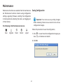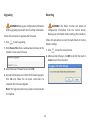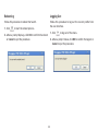
1
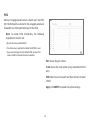
Business Solutions
User Manual
EGS2108P | EGS2110P | EGS5110P
version 1.0
EGS Smart Switch Series
8-Port Gigabit Switches
IMPORTANT
To install your Switch please refer to the
Quick Installation Guide included in the product packaging.
2
Table of Contents
Chapter 1 Product Overview ........................................... 4
Introduction/Package Contents ......................................... 5
Technical Specifications ........................................................ 6
Physical Interface ..................................................................... 7
Management Interface ........................................................... 9
Connecting the Switch to a Network .............................. 10
Web Access .................................................................................. 12
Chapter 2 Management ..................................................... 13
System ............................................................................................ 14
- IP Setting .................................................................................. 15
- Port Settings ............................................................................ 16
- PoE Management ................................................................... 17
- PoE Port Configuration ....................................................... 18
- Cable Diagnostics/Password .............................................. 20
- Zero Configuration .................................................................. 21
L2 Feature .................................................................................... 22
- Port Trunking ........................................................................... 22
- IGMP Snooping/Multicast Group List ....................... 23
- Port Mirroring .......................................................................... 24
- Loopback Detection .............................................................. 25
- Static MAC Address/Dynamic Address List ........ 26
3
VLAN ................................................................................................
- 802.1Q ........................................................................................
- PVID ..............................................................................................
- Port-based VLAN ...................................................................
QoS ...................................................................................................
- 802.1p Default Priority .....................................................
- CoS Priority Class ..................................................................
- Storm Control ...........................................................................
- Bandwidth Control .................................................................
27
27
29
30
32
32
33
34
35
Chapter 3 Maintenance.......................................................
Maintenance ................................................................................
Upgrading/Resetting ..........................................................
Rebooting/Logging Out .....................................................
Appendix ...............................................................................
FCC Interference Statement ................................................
IC Interference Statement ....................................................
CE Interference Statement ..................................................
36
37
38
39
40
41
42
44
Chapter 1
Product Overview
4
Introduction
The EGS Smart Switch Series are smart switch devices
specially designed to support Access Points and IP
Surveillance cameras, VOIP phones, and other PoE-Capable
. devices as well as other Ethernet-based networking
equipments or computers.The Smart Switch Series provide
simple, yet powerful PoE manageability with features
such as: IEEE 802.3af or IEEE 802.3at/af ports, PoE port
management, loopback detection, and IGMP snooping.
Package Contents
Your EGS Smart Switch package will contain the following
items*
• EnGenius Switch
• Quick Installation Guide
• Power Cord (EGS5110P Only)
• Power Adapter (EGS2108P & EGS2110P)
• Rack Mount Kit (EGS5110P Only)
• Wall Mount Kit (EGS2108P & EGS2110P)
• Ground Screw Kit (EGS2108P & EGS2110P)
*(all items must be in package to issue a refund):
Maximum data rates are based on IEEE 802.3ab standards. Actual throughput and range may vary depending on distance between devices or traffic and bandwidth load in the network.
Features and specifications subject to change without notice. Trademarks and registered trademarks are the property of their respective owners. For United States of America: Copyright
©2013 EnGenius Technologies, Inc. All rights reserved. Compliant with FCC - This equipment has been tested and found to comply with the limits for a Class A digital device, pursuant
to Part 15 of the FCC Rules. These limits are designed to provide reasonable protection against harmful interference in a residential installation. This equipment generates, uses, and can
radiate radio frequency energy and, if not installed and used in accordance with the instructions, may cause harmful interference to radio communications. Operation of this equipment
in a residential area is likely to cause harmful interference in which case the user will be required to correct the interference at his/her own expense.
5
Technical Specifications
Environment & Mechanical:
Temperature Range
Operating: 32 to 104°F / 0 to 40°C
Storage: -40 to 158°F / -40 to 70 °C
Humidity (non-condensing): 5% - 95%
Standard:
Switching Capacity:
20 Gbps (EGS5110P and EGS2110P)
16 Gbps(EGS2108P)
Max. Forwarding Rate (64kBytes): 14.88 Mpps
Forwarding Mode: Store and Forward
Packet Buffer Memory: 512K Bytes
Flash Memory: 4 MB
L2 Features:
Loopback Detection
IGMP Snooping v1/v2
Port Trunking
Port Mirroring: One to one and many to one
Static MAC Address
Dynamic MAC List
Bandwidth Control
802.1Q VLAN
Port-based VLAN
Storm Control
BootP/DHCP Client
Firmware Burn-Proof
Cable Diagnostic
CoS
PoE Management
Port Functions:
8 10/100/1000Mbps Ports in the front panel
2 1000Mbps SFP Slot (EGS5110P and EGS2110P)
PoE Capability:
PoE Standard: Port 1~8 Support IEEE 802.3at/af (EGS5110P)
PoE Capable Ports:
Port 1~8 can output up to 30W (EGS5110P)
Port 1~8 can output up to 15.4W (EGS2110P)
Ports: Port 1~4 can output up to 15.4W (EGS2108P)
PoE budget:
130 Watts (EGS5110P)
61.6 Watts (EGS2108P and EGS2110P)
LED Indicator
Device:
Power LED x1
Fault LED x1
PoE Max LED x1
LAN Mode LED x1
PoE Mode LED x1
SFP Ports: (EGS5110P and EGS2110P)
LAN/PoE Mode
Link/Act
6
Power on/off per port
Power Class Configuration
Power feeding with priority
User-defined power limit
Physical Interface
Dimensions and Weights
Dimensions and Weights
Desktop Design: EGS2108P & EGS2110P
Weight: 1.39 lb.
Width: 9.45”
Length: 4.13”
Height: 1.06”
Rack Mountable Design: EGS5110P
Weight: 4.45 lb.
Width: 12.99”
Length: 9.05”
Height: 1.7”
4
6
7
4
9
1
1
2
2
3
5
8
3
10
6
5
7
9
8
EGS2108P - Front
4
6
7
12
9
2
5
8
10
11
EGS5110P - Front
1
3
10
11
EGS5110P - Back
EGS2110P - Front
12
13
EGS 2108P/EGS2110P - Back
7
1 Power LED: Light off = Power off; Solid Light = Power On.
8 RJ-45 LAN Ports: 10/100/1000 Mbps RJ-45 LAN ports.
2 Fault LED: Light off = Normal Behavior; Solid Light = Error.
9 LAN Mode LED (Per Copper Port): Light off = No link is
established on the port; Solid Amber Light = A valid 10/100 Mpbs
link is established on the port; Solid Green Light = A valid 1000
Mbps link is established on the port.
3 PoE Max LED: Light off = Additional PoE device may still be added;
Solid Light = The PoE device’s output power has exceeded total
PoE limit. No additional devices can be powered on via PoE.
10Link/Act LED (Per Copper Port): Light off = No link is established
on the port; Solid Light = A valid link is established on the port;
Blinking Light = Packet transmission on the port.
4 LAN Mode LED: Light off = LAN mode is not activated; Solid Light
= LAN mode is activated.
5 PoE Mode LED: Light off = PoE mode is not activated; Solid Light
= PoE mode is activated.
11SFP Ports: Small form factor pluggable ports.
12Power Connector
6 LED Mode Selector: Press to change between LAN and PoE mode.
13Power Switch
7 Reset Button: Press to reset the device to factory default settings.
8
Management Interface
Each EnGenius Gigabit PoE or PoE+ Smart Switch features an embedded web interface for the monitoring and
management of your device.
9
Connecting the Switch to a Network
Discovery in a Network with a DHCP Server
5. Open a web browser on your computer. In the address bar of the web browser, enter 192.168.0.239 and click
Enter.
Use this procedure to setup the Switch within a network
that uses DHCP.
1.
Connect the supplied Power Adapter (cord) to the Switch
and plug the other end into an electrical outlet. Turn the
Power Switch on the back of the device to the ON
Position (for EGS2108P and EGS2110P). Verify the
Power LED indicator is lit on the Switch.
6. A login screen will appear. By default, the password is
password. Enter the current password of the Switch
and then click Login.
7. Once logged in, click IP Setting under and select DHCP.
2. Wait for the Switch to complete boot up. It might take
a minute for the Switch to complete boot up.
8.Click Apply to save the settings.
9. Connect the Switch to your network (DHCP enabled).
3. Connect one end of a Category 5/6 Ethernet cable into
the Gigabit (10/100/1000) Ethernet port on the switch
front panel and the other end to Ethernet port on the
computer. Verify that the LED on Ethernet ports of the
switch are green.
10.On the DHCP server, find and write down the IP address
allocated to the device. Use this IP address to access
the management interface.
4. Once your computer is on, ensure that your TCP/IP is set
to On or Enabled. Open Network Connections and then
click Local Area Connecton. Select Internet Protocol
Version 4 (TCP/IPv4). If your computer is already on a
network, ensure that you have set it to a Static IP Address
on the Interface (Example: 192.168.0.10 and the Subnet
Mask address as 255.255.255.0).
10
Discovery on a Network without a DHCP Server
4. Once your computer is on, ensure that your TCP/IP is set
to On or Enabled. Open Network Connections and then
click Local Area Connecton. Select Internet Protocol
Version 4 (TCP/IPv4).
This section describes how to set up an EnGenius Gigabit
PoE or PoE+ Smart Switch in a network without a DHCP
server. If your network has no DHCP service, you must
assign a static IP address to your Switch in order to log in
to the web-based switch management.
5.
1. Connect the supplied Power Adapter (cord) to the
Switch and plug the other end into an electrical outlet.
Turn the Power Switch on the back of the device to
the ON Position (for EGS2108P and EGS2110P). Verify
the Power LED indicator is lit on the Switch.
6. Open a web browser on your computer. In the address
bar of the web browser, enter 192.168.0.239 and click
Enter.
2. Wait for the Switch to complete boot up. It might take
a minute or so for the Switch to complete boot up.
3.
If your computer is already on a network, ensure that
you have set it to a Static IP Address on the Interface
(Example: 192.168.0.10 and the Subnet Mask address
as 255.255.255.0).
Connect one end of a Category 5/6 Ethernet cable into
the Gigabit (10/100/1000) Ethernet port on the Switch
front panel and the other end to Ethernet port on the
computer. Verify that the LED on Ethernet ports of the Switch are green.
If your Computer is already on a network, ensure that
you have set it to a Static IP Address on the interface
(Example: 192.168.0.10 and the Subnet Mask address as
255.255.255.0.).
7. A login screen will appear. By default, the password is
password. Enter the current password of the Switch
and then click Login.
8. Once logged in, click IP Setting under the System
Setting and select Static IP to configure the IP settings
of the management interface.
9. Enter the IP address, Subnet Mask and Gateway
10. Click Apply to update the system.
11
Web Access
Use this procedure to access the management interface
through a Web browser for device configuration.
1. Open a Web browser on your computer and enter
the following address (default): http://192.168.0.239.
2. On the login screen, use the following information:
Password: password
To make access to the web-based management interface
more secure, it’s highly reccomended that you change the
password to something more unique.
12
Chapter 2
Management
13
System
Summary
The navigation pane at the left of the web browser interface
contains a System tab that enables you to manage your
EnGenius Smart Switch with features under the following
main menu options:
The Summary screen contains general device information
including the device name, Firmware version, MAC address,
IP address, Gateway, and System Up Time.
•“Summary”
• “IP Setting”
• “Port Setting”
• “PoE Management”
• “Cable Diagnostics”
•“Password”
• “Zero Configuration”
Device Name: Shows the model name of the Switch
The description that follows in this chapter describes
configuring and managing system settings in the EnGenius
Smart Switch.
FW version: Shows the installed firmware version of the Switch
Serial Number: Shows the serial number of the Switch
Base MAC address: Shows the MAC address of the device
IP address: Shows the IP address assigned by DHCP server.
Gateway: Shows the Gateway of IP interface.
System up Time: Shows the amount of time since the most
recent device reset. The System Time is displayed in the
following format: days, hours, and minutes. For example,
the display will read: 3 days, 6 hours, 10 minutes.
14
IP Setting
To access the page, click IP Setting under the system menu.
The IP Setting screen contains fields for assigning IP
addresses. IP addresses are either defined as static or are
retrieved using the Dynamic Host Configuration Protocol
(DHCP). The DHCP assigns dynamic IP addresses to devices
on a network. DHCP ensures that network devices can
have a different IP address every time the device connects
to the network.
Note the following when configuring IP Addresses:
Dynamic IP Address (DHCP): Enable the IP address to be
configured automatically by the DHCP server. Selecting this
field disables the IP Address, Subnet mask, and Gateway fields.
If the device fails to retrieve an IP address through
DHCP, the default IP address is 192.168.0.239.
Static IP Address: Specifies that the IP address, Subnet
mask, and default Gateway must be manually configured.
IP Address: Enter the static IP address used to manage the
Switch.
Subnet Mask: Enter the IP address mask.
Gateway: Use this to configure the IP address of a router
on the same subnet as the management interface that
connects to other subnets.
Apply: Click APPLY to update the System Settings.
15
Port Settings
Port: Shows the port number.
Use the Port Setting to configure the speed and duplex
settings of each port.
Trunk: Port trunking allows you to assign physical links to
one logical link (trunk) that functions as a single, higherspeed link providing dramatically increased bandwidth.
Shows which trunk the port belongs to.
To access the page, click Port Setting under the system menu.
Link: Indicates whether the link is up or down at the physical
layer.
Speed: Use the drop down menu to select the port’s speed
and duplex mode. If you select Auto, the duplex mode
and speed will be set by the auto-negotiation. The port’s
maximum capability (full duplex and 1Gbps) and the factory
default is Auto.
Apply: Click APPLY to update the System Settings.
16
PoE Management
The PoE Management screen contains system PoE
information for monitoring the current power usage and
assign the total amount of power the Switch can provide
to all of its PoE ports. Ports 1~8 on the EGS5110P are
IEEE802.3at/af compliant ports. Each port is capable of
delivering up to 30W and a total PoE budget of 130W
for uninterrupted PoE use.To access the page, click PoE
Management under system menu.
Total Power Budget: Enter the amount of power the
Switch can provide to all ports.
Current Power Used: Shows the total amount of power
currently being delivered to all ports.
Apply: Click APPLY to apply the new settings to the system.
17
PoE Port Configuration
•Low – Set the PoE priority level as low.
The PoE Port Configuration screen contains system PoE
information for enabling PoE on the device and configure
per port PoE settings.
•Medium – Set the PoE priority level as medium.
•High – Set the PoE priority level as high.
•Critical – Set the PoE priority level as Critical.
To access the page, click PoE Port Configuration under
system menu.
Class(Auto): Shows the classification of the powered device.
The class defines the maximum power that can be provided
to the powered device. The possible field values are:
•Class 0 – The maximum power level at the Power Sourcing
Equipment is 15.4 Watts.
•Class 1 – The maximum power level at the Power Sourcing
Equipment is 4.0 Watts.
•Class 2 – The maximum power level at the Power Sourcing
Equipment is 7.0 Watts.
•Class 3 – The maximum power level at the Power Sourcing
Equipment is 15.4 Watts.
Port: Shows the specific port for which PoE parameters
are defined. PoE parameters are assigned to the powered
device that is connected to the selected port.
•Class 4 – The maximum power level at the Power Sourcing
Equipment is 30 Watts.
Select this option to base the power limit on the detected
class value. When this value is selected, the userconfigured value configured in the Power Limit field is
ignored.
Priority: Select the port priority if the power supply is low.
The field default is low. For example, if the power supply is
running at 99% usage, and port 1 is prioritized as high, but
port 6 is prioritized as low, port 1 is prioritized to receive
power and port 6 may be denied power. The possible field
values are: 4
Class(User defined): Select this option to base the power
limit on the value configured in the User Power Limit field.
18
Status: Shows the port’s PoE status. The possible field
values are:
User Power Limit: Set the maximum amount of power that
can be delivered by a port.
•Delivering Power – The device is enabled to deliver power
via the port.
Note: The User Power Limit can only be implemented
when the Class value is set to User-Defined.
•Disabled – The device is disabled for delivering power via the port.
•Test Fail – The powered device test has failed. For example, a
port could not be enabled and cannot be used to deliver power to
the powered device.
State:
•Enable – Enable the Device Discovery protocol and provides
power to the device using the PoE module. The Device Discovery
Protocol enables the device to discover Powered Devices attached to
the device interfaces and to learn their classification.
•Testing – The powered device is being tested. For example, a
powered device is tested to confirm it is receiving power from the
power supply.
•Disable – Disables the Device Discovery protocol and stops the
power supply to the device using the PoE module.
•Searching –The device is currently searching for a powered
device. Searching is the default PoE operational status.
•Fault – The device has detected a fault on the powered device
when the port is forced on. For example, the power supply
voltage is out of range, or there is a communication error with PoE
devices, a short occurs, or an unknown error occurs.
Apply: Click APPLY to update the system settings.
19
Cable Diagnostics
Password
The Cable Diagnostics setting provides information about
where connectivity may have failed on the Ethernet
cable. The tests use Time Domain Reflectometry (TDR)
technology to test the quality of the Ethernet cable for any
disconnection or failure points.
Click Password from the System section. The password
screen appears. You can set a new password. You must
enter the old and new passwords and confirm the new one.
Click Apply to enable the new password.
To access the page, click Password under system menu.
To access the page, click Cable Diagnostics under system
menu
Port: Select the port to which the cable is connected.
Password: Enter your password; the default password is
password.
Status: Shows the state of the cable.
Cable Length: Shows the approximate cable length.
New Password: Set the new password for the Switch
Test: Click Test to perform the cable tests for the selected
port.
Confirm: Enter the new password again
Apply: Click APPLY to update the system settings.
20
Zero Configuration
Bonjour: With Zero-Configuration networking, nearby
computers can discover its existence and automatically
determine the Switch’s IP address. And if that address is
a dynamically assigned address that changes, they can
automatically discover the new address in the future.
The Bonjour Zero-Configuration networking architecture
provides support for publishing and discovering TCP/IPbased services on a local area or wide area network. Bonjour
lets you connect device to your network without the need
to assign it a specific IP address or manually enter that
address into each computer.The Bonjour service is enabled
or disabled through the Zero Configuration page.
Apply: Click APPLY to update the system settings.
To access the page, click Zero configuration under system
menu
21
L2 Feature
The L2 Feature menu enables port trunking, control of
multicast traffic flooding, port mirroring, cabling loop
detection and MAC address table management.
Port Trunking
Port trunking allows you to assign physical links to one
logical link that functions as a single, higher-speed link
providing dramatically increased bandwidth. When large
numbers of users need to access shared resources such as
data base storage, the connection to the storage device can
become a bottleneck. The solution is to use port trunking
to bundle multiple connections and use the combined
bandwidth as if it were a single larger pipe.
Mode: Click
and then select Enable or Disable a trunk
from the drop-down menu. You must set the mode to
Enabled before you can edit the member ports.
Note: You must enable trunk mode before you can add
a port to a trunk group.
Member Ports: Click
and then click the Member Ports
bar to display the ports. Check the box to select which
ports are members of the trunk.
To access the page, click Port Trunking under L2 Feature
Click the Apply button
to accept the changes or the
Cancel button
to discard them.
Group: Shows the Group number.
22
IGMP Snooping
Multicast Group List
Internet Group Management Protocol (IGMP) Snooping is a
feature that allows a Switch to forward multicast traffic
intelligently on the Switch. Based on the IGMP query and
report messages, the Switch forwards traffic only to the
ports that request the multicast traffic.
The Multicast Group List screen displays the port to the
Multicast Service Group.
To access the page, click Multicast Group List under L2
Feature
The Switch can limit flooding of traffic to IGMP designated
ports.
Group IP: Shows the Multicast group IP address.
To access the page, click IGMP Snooping under L2 Feature.
VID: Shows the VLAN ID that the Multicast group is
operating over.
Member Ports: Shows Multicast Group Member Ports.
Setting:
•Enable – The Switch snoops all IGMP packets it receives to
determine which segments should receive packets directed to the
group address.
•Disable – The switch does not snoop IGMP packets.
Apply: Click Apply to update system settings.
23
Port Mirroring
Port Mirroring monitors and mirrors network traffic by
forwarding copies of incoming and outgoing packets from
one port to a monitoring port. Port mirroring can be used
as a diagnostic tool as well as a debugging feature. Port
mirroring is needed for traffic analysis on a switch because
a switch normally sends packets only to the port to which
the destination device is connected.
To access the page, click Port Mirroring under the L2
Feature.
Direction: Select received, transmitted, or bidirectional
traffic is mirrored.
Source Port: Selects the ports from which the packets are
mirrored.
Destination Port: Select the port to which port traffic is
copied.
Apply: Click Apply in order for settings to take effect.
24
Loopback Detection
Use the Loopback Detection function to configure the
system to shut down the current port once the port is
found in a loop. In addition, it will send a trap message.
When Spanning Tree Protocol (STP) is not enabled in
the network, the Loopback Detection function can be
used to detect the loop created by a specific port. For
users connecting unmanaged Switches, the Loopback
Detection function shuts a port when packets are sent and
received from the same port; a loopback effect. The port is
automatically unlocked after the recovery period times out.
Time Interval: Enter time interval that traffic is allowed to
flow over a cabling loop before the looped ports are shut
down.
To access the page, click Loopback Detection under L2
Feature.
Recovery Time: Enter time interval after ports are shut
down before they are automatically re- enabled.
Apply: Click Apply in order for the settings to take effect.
25
Static MAC Address
Dynamic Address List
The Static Addresses screen contains a list of static MAC
addresses. Static Addresses are added and removed from
the Static Addresses screen.
The Dynamic Address contains information about the MAC
address table.
To access the page, click Static MAC Address under
the L2 Feature menu.
Index: This shows the internal index for this MAC address
table entry.
Port: Shows the port from which traffic to a destination
MAC address is sent.
Index: Shows the internal index for this MAC address table
entry.
VID: Shows the VLAN ID that traffic to a destination MAC
Port: Select the port.
address is sent.
VID: Select the VLAN ID corresponding to the MAC address
to add.
MAC Address: Shows the destination MAC address that is
matched to traffic.
MAC Address: Specify the MAC address to add.
Add: Add a new entry to the MAC address table.
Edit: To edit an existing entry listed in the MAC address
table.
Delete: To delete an existing entry listed in the MAC
address table.
26
VLAN
A VLAN is a group of ports that form a logical Ethernet
segment on an Ethernet switch. VLANs let you segment
your network through the switch’s management software
so that you can group nodes with related functions into
their own separate, logical LAN segments.
VID: Specify the VLAN Identifier for the new VLAN. The
range of the VLAN ID is 1-4094.
802.1Q
Name: Specify a name for the VLAN.
The IEEE 802.1Q specification establishes a standard
method for tagging Ethernet frames with VLAN membership
information. The key for the IEEE 802.1Q to perform the
functions is in its tags. 802.1Q-compliant Switch ports can
be configured to transmit tagged or untagged frames. A tag
field containing VLAN (and/or 802.1p priority) information
can be inserted into an Ethernet frame. When using 802.1Q
VLAN configuration, you configure ports to be a part of a
VLAN group. When a port receives data tagged for a VLAN
group, the data is discarded unless the port is a member of
the VLAN group.
Tagged Ports: Frames transmitted from this port are
tagged with the VLAN ID.
Untagged Ports: Frames transmitted from this port are
untagged.
Important: Port-based VLAN and 802.1Q VLAN
are mutually exclusive. If you enable port-based VLAN,
then 802.1Q VLAN is disabled.
Note: All ports with a VID of 1 are assigned to the
default VLAN.
Enabled: Enable 802.1Q VLANs. This feature is enabled by
default.
27
5. Click the Untagged Ports text box to show the untagged
ports dialog box.
Adding, Editing, and Deleting Items in the List
6. Click a radio button in the Untagged Ports row to select
a port.
To add an item to the 802.1Q list, follow these steps:
1. Click the Add button
7.Click Confirm to accept the changes or Cancel to discard
them.
.
2. Enter the VID and name in the VID and Name text boxes.
3.Click the Tagged Ports text box to show the tagged
ports dialog box.
To delete an item in the 802.1Q list, follow these steps:
1.Click the Delete button
in the row you want to
remove. A confirmation dialog is displayed.
4. Click a radio button in the tagged ports row to select a
port.
2.Click OK to continue or Cancel to abort the changes.
28
PVID
When an Untagged packet enters a Switch port, the PVID
(Port VLAN ID) will be attacted to the untagged packet and
forwarded to a VLAN specified ID part of the PVID.
Note: To enable PVID functionality, the following
requirements must be met:
• All ports must have a defined PVID.
• If no other value is specified, the default VLAN PVID is used.
• If you want to change the port’s default PVID, you must first
create a VLAN that includes the port as a member.
Port: Shows the port number.
Trunk: Shows the trunk number (if any are defined for this
port).
PVID: Select one or more ports and then click here to select
a PVID.
Apply: Click APPLY to update the system settings.
29
Port-based VLAN
A port-based VLAN is a group of ports on a Gigabit Ethernet
Switch that form a logical Ethernet segment. Each port
of a port-based VLAN can belong to only one VLAN at a
time. A port-based VLAN can have as many or as few ports
as needed. The VLAN can consist of all the ports on an
Ethernet switch, or just a few ports.
Enabled: Click this to enable port-based VLANs. This
feature must be enabled to configure a port-based VLAN.
Adding, Editing, and Deleting Items in the List
Important: Port-based VLAN and 802.1Q VLAN
are mutually exclusive. If you enable port-based VLAN,
then 802.1Q VLAN is disabled
To create Port-based VLAN, follow these steps:
1. Click the Add button
VID: Specifies a VLAN identifier. The range is 2 to 4094.
The VID of 1 is reserved for the default VLAN. The VID
cannot be the same as the VID of an existing VLAN on the
switch.
.
2. Enter the VID and name in the VID and Name text boxes.
Name: Specifies a name of a port-based VLAN.
Member Ports: Shows which ports belong to this portbased VLAN.
30
3.Click the Member Ports text box to show the ports
dialog box.
3. Click the Member Ports text box to show the member
ports dialog box.
4. Select a port to add it to the Port-based VLAN.
4. Select a port to add it to the Port-base VLAN.
5. Click Confirm to accept the changes or Cancel to discard
them.
5. Click Confirm to accept the changes or Cancel to discard
them.
To edit an item in the 802.1Q list, follow these steps:
1. Click the Edit button
.
To delete an item in the 802.1Q list, follow these steps:
2. Enter the VID and name in the VID and Name text boxes.
1. Click the Delete button
to remove the Port-base
VLAN. A confirmation dialog is displayed.
2. Click OK to continue or Cancel to abort the changes.
31
QoS
The QoS enables traffic to be prioritized, excessive
broadcast and multicast traffic to be avoided and overall
bandwidth to be limited on a port-by-port basis. .
802.1p Default Priority
IEEE 802.1p specification enables Switches to prioritize
traffic and perform dynamic multicast filtering. The
prioritization specification works at the media access control
(MAC) framing layer (layer 2). The 802.1p header includes a
three-bit field for prioritization, which allows packets to be
grouped into various traffic classes. The 802.1p traffic is
simply classified and sent to the destination; no bandwidth
reservations are established. The priority level is from 0
to 7. EnGenius Smart Switch supports four class quality
levels: low, normal, medium, and high. To find out how to
map the priority value to one of the four classes, refer to
“CoS Priority Class” on page 33.
Port: Shows the port number.
Trunk: Shows the trunk number (if any are defined for this
port). Ports assigned to the same trunk group are assigned
the same priority level.
Priority: Select the Priority for untagged traffic arriving on
this port.
Apply: Click Apply to update system settings.
32
CoS Priority Class
Without CoS, most traffic received by a Switch is forwarded
with the same priority it had upon entering the switch. In
many cases, such traffic is ‘‘normal’’ priority and competes
for bandwidth with all other normal-priority traffic,
regardless of its relative importance to your organization’s
mission. CoS helps to keep the most important network
traffic moving at an acceptable speed, regardless of current
bandwidth usage. This means you can manage available
bandwidth so that the switch transmits the most important
traffic first. Click the CoS Priority Class link under the QoS
menu to define which 802.1p/Q prior- ity class (low, normal,
medium, or high) is applied to untagged ingress traffic.
Priority: Shows the Priority Code Point (PCP) that are from
0 to 7.
Class: Select the Class of Service (CoS) that is applied
to traffic. The CoS setting let you may each of the eight
priority levels to one of four internal hardware priority
queues: High, Medium, Normal and Low.
Apply: Click Apply to update system settings.
33
Storm Control
The Storm Control feature provides the ability to control
the receive rate of broadcast, multicast, and unknown
unicast packets. Storm Control prevents traffic on a LAN
from being disrupted by a broadcast, multicast, or unicast
storm on a port. A LAN storm occurs when packets flood
the LAN, creating excessive traffic and degrading network
performance. Errors in the protocol-stack implementation,
mistakes in network configuration, or users issuing a
denial-of-service attack can cause a storm. Storm control
uses rising and falling thresholds to block and then restore
the forwarding of broadcast, unicast, or multicast packets.
Port: Select type of traffic will be limited.
• Unknown Unicast: If the rate of unknown L2 unicast (destination
lookup failure) traffic ingressing on an interface increases beyond the
configured threshold, the traffic will be dropped.
• Multicast: If the rate of L2 multicast traffic ingressing on an interface
increases beyond the configured threshold, the traffic will be
dropped.
Click the Storm Control link under the QoS menu to limit
excessive flooding caused by a packet storm.
• Broadcast: If the rate of L2 broadcast traffic ingressing on an
interface increases beyond the configured threshold, the traffic will
be dropped.
Threshold: Specify how many packets per second are
allowed to go forwarded: Low = 100 packets per second,
Medium = 500 packets per second, High =1000 packets
per second.
34
Bandwidth Control
The Bandwidth Control allows network managers to define
the bandwidth settings for a specified port’s transmitting
and receiving data rates. Bandwidth Control feature is used
to set the limit of transmitting and receiving data rate for
any selected port.
Port: Shows the port number.
Trunk: Shows the trunk number (if any are defined for
this port).
Tx: Specify the maximum bandwidth to be received.
Rx: Specify the maximum bandwidth to be transmitted.
Apply: Click Apply to update system settings.
35
Chapter 3
Maintenance
36
Maintenance
Saving Configuration
Maintenance functions are available from the maintenance
bar. Maintenance functions include: saving configuration
settings, upgrading firmware, resetting the configuration
to factory defaults, rebooting the device, and logging out
of the interface.
Important: You must save any setting changes
before rebooting. Failure to save results in loss of new
configuration changes.
The following is the Maintenance menu bar.
Follow this procedure to save the configuration,
1. Click to save the entire configuration changes you
have made to the device to Switch.
2. Click OK.
37
Upgrading
Resetting
WARNING! Backup your configuration information
before upgrading to prevent loss of setting information.
WARNING! The Reset function will delete all
configuration information from the current device.
Backup your information before starting this procedure.
Follow this procedure to upgrade the Firmware.
1. Click
Follow this procedure to reset the Switch back to factory
default settings.
to start upgrading.
1.Click Choose File. When a window opens, browse to the
location of your new Firmware.
1. Click
to start the reset process.
2. When a prompt displays, click OK to confirm the reset or
Cancel to quit the procedure.
3. Select the new Firmware file and click OK.
4. A prompt will displays to confirm the Firmware Upgrade.
Click OK and follow the on-screen instructions to
complete the Firmware Upgrade.
Note: The Upgrade process may require a few minutes
to complete.
38
Rebooting
Logging Out
Follow this procedure to reboot the Switch.
Follow this procedure to log out the current profile from
the user interface.
1. Click
to start the reboot process.
1. Click
2. When a prompt displays, click OK to confirm the reboot
or Cancel to quit the procedure.
to log out of the menu.
2. When a prompt shows, click OK to confirm the logout or
Cancel to quit the procedure.
39
Appendix
40
Appendix A
Federal Communication Commission Interference Statement
This equipment has been tested and found to comply with the limits for a Class B dig- ital device, pursuant to Part 15 of the FCC Rules. These limits are
designed to pro- vide reasonable protection against harmful interference in a residential installation. This equipment generates uses and can radiate
radio frequency energy and, if not installed and used in accordance with the instructions, may cause harmful interfer- ence to radio communications.
However, there is no guarantee that interference will not occur in a particular installation. If this equipment does cause harmful interfer- ence to radio
or television reception, which can be determined by turning the equip- ment off and on, the user is encouraged to try to correct the interference by
one of the following measures:
• Reorient or relocate the receiving antenna.
• Increase the separation between the equipment and receiver.
• Connect the equipment into an outlet on a circuit different from that to which the receiver is connected.
• Consult the dealer or an experienced radio/TV technician for help.
WARNING!
Any changes or modifications not expressly approved by the party responsible for compliance could void the user’s authority to operate this equipment.
This device complies with Part 15 of the FCC Rules. Operation is subject to the fol- lowing two conditions: (1) This device may not cause harmful
interference, and (2) this device must accept any interference received, including interference that may cause undesired operation.
Radiation Exposure Statement
WARNING! This equipment complies with FCC radiation exposure limits set forth for an uncontrolled environment. This device complies
with FCC RF Exposure limits set forth for an uncontrolled environment, under 47 CFR 2.1093 paragraph (d)(2). This transmitter must not
be co-located or operating in conjunction with any other antenna or transmitter.
41
Appendix B - IC Interference Statement
Industry Canada Statement
This device complies with RSS-210 of the Industry Canada Rules. Operation is subject to the following two conditions: (1) This device
may not cause harmful interference, and (2) this device must accept any interference received, including interference that may cause
undesired operation.
Ce dispositif est conforme à la norme CNR-210 d’Industrie Canada applicable aux appareils radio exempts de licence. Son fonctionnement
est sujet aux deux conditions suivantes: (1) le dispositif ne doit pas produire de brouillage préjudiciable, et (2) ce dispositif doit accepter
tout brouillage reçu, y compris un brouillage susceptible de provoquer un fonctionnement indésirable.
Caution:
(i) the device for operation in the band 5150-5250 MHz is only for indoor use to reduce the potential for harmful interference to cochannel mobile satellite systems;
(ii) high-power radars are allocated as primary users (i.e. priority users) of the bands 5250-5350 MHz and 5650-5850 MHz and that these
radars could cause interference and/or damage to LE-LAN devices.
Avertissement:
(i) les dispositifs fonctionnant dans la bande 5150-5250 MHz sont réservés uniquement pour une utilisation à l’intérieur afin de réduire
les risques de brouillage préjudiciable aux systèmes de satellites mobiles utilisant les mêmes canaux;
(ii) De plus, les utilisateurs devraient aussi être avisés que les utilisateurs de radars de haute puissance sont désignés utilisateurs
principaux (c.-à-d., qu’ils ont la priorité) pour les bandes 5250-5350 MHz et 5650-5850 MHz et que ces radars pourraient causer du
brouillage et/ou des dommages aux dispositifs LAN-EL.
42
FOR MOBILE DEVICE USAGE
Radiation Exposure Statement
This equipment complies with IC radiation exposure limits set forth for an uncontrolled environment. This equipment should be installed and operated
with minimum distance 20cm between the radiator & your body.
Pour l’utilisation de dispositifs mobiles)
Déclaration d’exposition aux radiations:
Cet équipement est conforme aux limites d’exposition aux rayonnements IC établies pour un environnement non contrôlé. Cet équipement doit
être installé et utilisé avec un minimum de 20cm de distance entre la source de rayonnement et votre corps.
43
Appendix C - CE Interference Statement
Europe – EU Declaration of Conformity
This device complies with the essential requirements of the R&TTE Directive 1999/5/EC. The following test methods have been applied in order
to prove presumption of conformity with the essential requirements of the R&TTE Directive 1999/5/EC:
•EN60950-1
Safety of Information Technology Equipment
•EN50385
Generic standard to demonstrate the compliance of electronic and electrical apparatus with the basic restrictions related to human exposure
to electromagnetic fields (0 Hz - 300 GHz)
• EN 300 328
Electromagnetic compatibility and Radio spectrum Matters (ERM); Wideband Transmission systems; Data transmission equipment operating
in the 2,4 GHz ISM band and using spread spectrum modulation techniques; Harmonized EN covering essential requirements under article
3.2 of the R&TTE Directive
• EN 301 893
Broadband Radio Access Networks (BRAN); 5 GHz high performance RLAN; Harmonized EN covering essential requirements of article 3.2 of
the R&TTE Directive
• EN 301 489-1
Electromagnetic compatibility and Radio Spectrum Matters (ERM); ElectroMagnetic Compatibility (EMC) standard for radio equipment and
services; Part 1: Common technical requirements
• EN 301 489-17
Electromagnetic compatibility and Radio spectrum Matters (ERM); ElectroMagnetic Compatibility (EMC) standard for radio equipment and
services; Part 17: Specific conditions for 2,4 GHz wideband transmission systems and 5 GHz high performance RLAN equipment
44
This device is a 5GHz wideband transmission system (transceiver), intended for use in all EU member states and EFTA countries, except in France
and Italy where restrictive use applies.
In Italy the end-user should apply for a license at the national spectrum authorities in order to obtain authorization to use the device for setting
up outdoor radio links and/or for supplying public access to telecommunications and/or network services.
This device may not be used for setting up outdoor radio links in France and in some areas the RF output power may be limited to 10 mW EIRP
in the frequency range of 2454 – 2483.5 MHz. For detailed information the end-user should contact the national spectrum authority in France.
Česky [Czech]
[Jméno výrobce] tímto prohlašuje, že tento [typ zařízení] je ve shodě se základními požadavky a dalšími příslušnými
ustanoveními směrnice 1999/5/ES.
Dansk [Danish]
Undertegnede [fabrikantens navn] erklærer herved, at følgende udstyr [udstyrets typebetegnelse] overholder de
væsentlige krav og øvrige relevante krav i direktiv 1999/5/EF.
Deutsch [German]
Hiermit erklärt [Name des Herstellers], dass sich das Gerät [Gerätetyp] in Übereinstimmung mit den grundlegenden
Anforderungen und den übrigen einschlägigen Bestimmungen der Richtlinie 1999/5/EG befindet.
Eesti [Estonian]
Käesolevaga kinnitab [tootja nimi = name of manufacturer] seadme [seadme tüüp = type of equipment] vastavust
direktiivi 1999/5/EÜ põhinõuetele ja nimetatud direktiivist tulenevatele teistele asjakohastele sätetele.
English
Hereby, [name of manufacturer], declares that this [type of equipment] is in compliance with the essential requirements
and other relevant provisions of Directive 1999/5/EC.
Español [Spanish]
Por medio de la presente [nombre del fabricante] declara que el [clase de equipo] cumple con los requisitos esenciales
y cualesquiera otras disposiciones aplicables o exigibles de la Directiva 1999/5/CE.
Ελληνική [Greek]
ΜΕ ΤΗΝ ΠΑΡΟΥΣΑ [name of manufacturer] ΔΗΛΩΝΕΙ ΟΤΙ [type of equipment] ΣΥΜΜΟΡΦΩΝΕΤΑΙ ΠΡΟΣ ΤΙΣ ΟΥΣΙΩΔΕΙΣ
ΑΠΑΙΤΗΣΕΙΣ ΚΑΙ ΤΙΣ ΛΟΙΠΕΣ ΣΧΕΤΙΚΕΣ ΔΙΑΤΑΞΕΙΣ ΤΗΣ ΟΔΗΓΙΑΣ 1999/5/ΕΚ.
45
Français [French]
Par la présente [nom du fabricant] déclare que l’appareil [type d’appareil] est conforme aux exigences essentielles et aux
autres dispositions pertinentes de la directive 1999/5/CE.
Italiano [Italian]
Con la presente [nome del costruttore] dichiara che questo [tipo di apparecchio] è conforme ai requisiti essenziali ed alle
altre disposizioni pertinenti stabilite dalla direttiva 1999/5/CE.
Latviski [Latvian]
Ar šo [name of manufacturer / izgatavotāja nosaukums] deklarē, ka [type of equipment / iekārtas tips] atbilst Direktīvas
1999/ 5/EK būtiskajām prasībām un citiem ar to saistītajiem noteikumiem.
Lietuvių [Lithuanian]
Šiuo [manufacturer name] deklaruoja, kad šis [equipment type] atitinka esminius reikalavimus ir kitas 1999/5/EB
Direktyvos nuostatas.
Nederlands [Dutch]
Hierbij verklaart [naam van de fabrikant] dat het toestel [type van toestel] in overeenstemming is met de essentiële eisen
en de andere relevante bepalingen van richtlijn 1999/5/EG.
Malti [Maltese]
Hawnhekk, [isem tal-manifattur], jiddikjara li dan [il-mudel tal-prodott] jikkonforma mal-ħtiġijiet essenzjali u ma provvedimenti
oħrajn relevanti li hemm fid-Dirrettiva 1999/5/EC.
Magyar [Hungarian]
Alulírott, [gyártó neve] nyilatkozom, hogy a [... típus] megfelel a vonatkozó alapvetõ követelményeknek és az 1999/5/EC
irányelv egyéb elõírásainak.
Polski [Polish]
Niniejszym [nazwa producenta] oświadcza, że [nazwa wyrobu] jest zgodny z zasadniczymi wymogami oraz pozostałymi
stosownymi postanowieniami Dyrektywy 1999/5/EC.
Português [Portuguese]
[Nome do fabricante] declara que este [tipo de equipamento] está conforme com os requisitos essenciais e outras
disposições da Directiva 1999/5/CE.
Slovensko [Slovenian]
[Ime proizvajalca] izjavlja, da je ta [tip opreme] v skladu z bistvenimi zahtevami in ostalimi relevantnimi določili direktive
1999/5/ES.
Slovensky [Slovak]
[Meno výrobcu] týmto vyhlasuje, že [typ zariadenia] spĺňa základné požiadavky a všetky príslušné ustanovenia Smernice
1999/5/ES.
Suomi [Finnish]
[Valmistaja = manufacturer] vakuuttaa täten että [type of equipment = laitteen tyyppimerkintä] tyyppinen laite on
direktiivin 1999/5/EY oleellisten vaatimusten ja sitä koskevien direktiivin muiden ehtojen mukainen.
Svenska [Swedish]
Härmed intygar [företag] att denna [utrustningstyp] står I överensstämmelse med de väsentliga egenskapskrav och
övriga relevanta bestämmelser som framgår av direktiv 1999/5/EG.
46