1
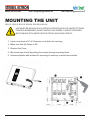
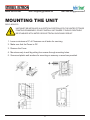
PHONE:
800-355-4945
EMAL:
[email protected]
WEB:
www.energyproducts.biz
HYDRO-SHARK 3
®
MODULATING MICRO BOILERS
Radiant Floor Heating Applications
INSTALLATION INSTRUCTIONS FOR THE LICENSED PLUMBER & ELECTRICAN
MODEL #’S:
MODEL #’S:
MODEL #’S:
• SH3-07
• SH3-10
• SH3-12
• SH3-14
• SH3-19
• SH3-24
• SH3-29
• SH3-36
Warning: Not to be used with potable water systems
1
PHONE:
800-355-4945
EMAL:
[email protected]
WEB:
www.energyproducts.biz
Table of Contents
Important
3
General
3
4-5
Mounting the units
6
Fluid connections
7-9
Electrical connections
Technical data
10
Troubleshooting
11
Spare parts
11
Warranty
12
Electrical & Mechanical Diagrams
13-19
Filling the System
20-23
2
PHONE:
800-355-4945
EMAL:
[email protected]
WEB:
www.energyproducts.biz
IMPORTANT!
BOILERS ARE TO BE USED FOR RADIANT FLOOR HEATING ONLY!
THIS MANUAL MUST BE READ CAREFULLY BEFORE ATTEMPTING TO INSTALL THE HYDRO-SHARK
BOILERS. IF YOU DO NOT FOLLOW THE SAFETY RULES OR THE INSTRUCTIONS OUTLINED IN THIS
MANUAL, THE UNIT MAY NOT OPERATE PROPERLY AND IT COULD CAUSE PROPERTY DAMAGE,
SERIOUS BODILY INJURY AND/OR DEATH.
STIEBEL ELTRON, INC. WILL NOT BE LIABLE FOR ANY DAMAGES BECAUSE OF FAILURE TO COMPLY
WITH INSTALLATION AND OPERATING INSTRUCTIONS OUTLINED IN THIS MANUAL OR BECAUSE
OF IMPROPER USE. IMPROPER USE INCLUDES THE USE FOR THIS APPLIANCE TO HEAT ANY LIQUID
OTHER THAN WATER OR PROPYLENE GLYCOL. FALURE TO COMPLY WITH THE INSTALLATION AND
OPERATING INSTRUCTIONS OR IMPROPER USE VOIDS THE WARRANTY. NEVER REMOVE THE
UNITS FRONT COVER UNLESS POWER IS TURNED OFF.
IF YOU HAVE ANY QUESTIONS REGARDING THE INSTALLATION OR OPERATION OF THES BOILER,
PLEASE CALL OUR TECHNICAL SERVICE LINE AT 800-582-8423 (U.S.A. AND CANADA ONLY). IF YOU
ARE CALLING OUTSIDE OF THE U.S. AND CANADA CALL (413)-538-7850 AND WE WILL REFER YOU TO
A QUALIFIED STIEBEL ELTRON SERVICE REPRESENTATIVE IN YOUR AREA.
GENERAL
• The output of heat from the boiler is electronically controlled. The Boiler will deliver any water
tempeture between 86° F and 140° F for the SH3-12,SH3-14, SH3-19, SH3-24, SH3-36 and
120° F for the SH3-07 and SH3-10. Please set the desired water delivery tempeture using the knob
on the front cover.
• When the Power light is flashing, full element power is being applied. When the Power light is not
flashing, the element power is being modulated to the water delivery temperature.
• Recommended Setting for radiant floor heating in cement or gypcrete is 110° F to 125° F.
• Recommended Setting for staple up or baseboard 140° F.
3
PHONE:
800-355-4945
EMAL:
[email protected]
WEB:
www.energyproducts.biz
MOUNTING THE UNIT
SH3-12, SH3-14, SH3-19, SH3-24, SH3-29 & SH3-36
UNIT MUST BE INSTALLED IN A VERTICAL POSITION WITH THE WATER FITTINGS
POINTING DOWNWARD, DO NOT INSTALL UNIT WHERE IT WOULD ROUTINELY
BE SPLASHED WITH WATER OR ELECTRICAL SHOCK MAY RESULT.
1. Leave a minimum of 5” of Clearance on all sides for servicing.
2. Make sure that the Power is Off.
3. Remove the Cover.
4. Mount securely to wall by putting four screws through mounting holes.
5. Screw and plastic wall anchors for mounting on masonry or wood are provided.
4
PHONE:
800-355-4945
EMAL:
[email protected]
WEB:
www.energyproducts.biz
MOUNTING THE UNIT
SH3-3 & SH3-10
UNIT MUST BE INSTALLED IN A VERTICAL POSITION WITH THE WATER FITTINGS
POINTING DOWNWARD, DO NOT INSTALL UNIT WHERE IT WOULD ROUTINELY
BE SPLASHED WITH WATER OR ELECTRICAL SHOCK MAY RESULT.
1. Leave a minimum of 5” of Clearance on all sides for servicing.
2. Make sure that the Power is Off.
3. Remove the Cover.
4. Mount securely to wall by putting four screws through mounting holes.
5. Screw and plastic wall anchors for mounting on masonry or wood are provided.
5
PHONE:
800-355-4945
EMAL:
[email protected]
WEB:
www.energyproducts.biz
FLUID CONNECTIONS
NOTE: EXCESSIVE HEAT FROM SOLDERING COPPER PIPES NEAR THE BOILER MAY CAUSE DAMAGE.
1. All plumbing work must comply with the national, state, local & any other applicable codes.
2. Make sure the radiant floor system has been purged & is free of floating debris.
3. The return side (inlet) is on the right side of the unit, the supply side (outlet) is on the
left of the unit.
4. A pressure & temprature relief valve should be installed on the hot water supply side
(outlet) of the unit.
5. The boiler is designed for a connection to copper tubing and/or PEX tubing. If soldering the
unit is necessary, please direct the flame away from the housing of the unit to avoid damage.
6. When all plumbing work is completed, check for leaks & take corrective action
before proceeding.
SUPPLY OUTLET
RETURN INLET
6
PHONE:
800-355-4945
EMAL:
[email protected]
WEB:
www.energyproducts.biz
ELECTRICAL CONNECTIONS
WARNING: BEFORE BEGINNING ANY WORK ON THE ELECTRIC INSTALLATION, BE SURE THAT
THE MAIN BREAKER PANEL SWITCHES ARE “OFF” TO AVOID ANY DANGER OF ELECTRIC SHOCK.
ALL MOUNTING AND PLUMBING MUST BE COMPLETED BEFORE PROCEEDING WITH ELECTRICAL
HOOK-UP. WHERE REQUIRED BY LOCAL,STATE OR NATIONAL ELECTRICAL CODES THE CIRCUITS
SHOULD BE EQUIPPED WITH A “ GROUND FAULT INTERRUPTER”.
1. All electrical work must comply with the national, state, local & any other applicable codes.
2. The boiler should be connected to properly grounded dedicated branch circuits of proper
voltage rating. Ground must be brought to the ‘Ground’ at the circuit breaker panel.
3. A SH3-07, SH3-10 & SH3-12 can be connected to ONE independent circuit (Figure A & B).
4. A SH3-14, SH3-19 & SHE-24 can be connected to TWO independent circuits (Figure C).
Use supply table (See Technical Data table “A” on page XX). Protected by TWO double pole
breakers sized for the load.
5. A SH3-29,SH3-36 can be connected to THREE independent circuits (Fig D.). Use supply
cable (See Technical Data Table “A”) protected by THREE double pole breakers sized
for the load.
6. Cut the electrical connection cable to length and strip.
7. The wire must be fed through the knockouts located between the Supply and Return fluid
connections. The “Live” wires must be connected to the slots on the terminal block marked
“L” and “L”. The ground wire must be connected to slot marked with the ground symbol.
8. Reinstall the cover screws.
WARNING! As with any electrical appliance, failure to electrically ground may result in serious injury or Death.
7
PHONE:
800-355-4945
EMAL:
[email protected]
Figure A
SH3-07 & SH3-10
Figure B
SH3-12
8
WEB:
www.energyproducts.biz
PHONE:
800-355-4945
EMAL:
SH3-29,SH3-36
SH3-36
SH3-24
[email protected]
SH3-14,SH3-19,SH3-24
WEB:
www.energyproducts.biz
SH3-12
SH3-29
SH3-14, SH3-19
9
SH3-12
PHONE:
800-355-4945
EMAL:
[email protected]
WEB:
www.energyproducts.biz
TECHNICAL DATA
“A” MODEL - 14 1/4 H X 7 7/8 W X 4 1/8 D - 1/2 PLUMBING FITTINGS
MODEL
KW
BTU
VOLTS
AMPS
BRKR
WT-LBS
SH3-07
7.2
24,573
240
30
(1)40
5.9
SH3-10
9.6
32,764
240
40
(1)50
5.9
“B” MODEL - 14 1/2 H X 16 5/8 W X 4 5/8 D - 3/4 PLUMBING FITTINGS
MODEL
KW
BTU
VOLTS
AMPS
BRKR
WT-LBS
SH3-12
12
40,968
240
50
(1)70
17
SH3-14
14.4
49,161
240
60
(2)40
20
SH3-19
19.2
65,548
240
80
(2)50
20
SH3-24
24
81,936
240
100
(2)70
20
“C” MODEL - 14 1/2 H X 16 5/8 W X 4 5/8 D 3/4 PLUMBING FITTINGS
MODEL
KW
BTU
VOLTS
AMPS
BRKR
WT-LBS
SH3-29
28.8
98,323
240
120
(3)50
24
SH3-36
36
122,904
240
150
(3)70
24
NOTE:
1. Boilers are considered a continuous load.
2. Copper conductors only.
SERVICE BULLETIN: Polarity matters on the Hydro-Shark Models with multiple circuits. On models
Sh3-14,19,24,29 and 36 the polarity of L1/L2 maters. If the installer places L1 on the left side of circuit
1, than L1 has to be placed on the left side of circuit 2 (SH3-14,19,24) and circuit 3 (SH3-29,36).
It does not matter if L1 or L2 is placed on the left or right side on the wireing block. It only
maters that all circuits are wired consistently, with L1 either always on the left or always on
the right. If the boiler will not run, reverse the L1 and L2 wires on one or two of the wiring
block to make the “polarity” consistent. The Factory is making changes to the interior wiring
so that the L1/L2 Polarity will not mater in the future. -May 14,2009
10
PHONE:
EMAL:
800-355-4945
WEB:
[email protected]
www.energyproducts.biz
TROUBLE SHOOTING
SYMPTOM
POSSIBLE CAUSE
SOLUTION
NO HOT WATER
• No Power
• Safety thermal cut-off tripped
• Not enough flow rate to activate unit
• Plugged flow sensor
• Utility Controlling Load
• Reset Thermal cut-off
• Wrong size Pump
• Activate thermostat
• Clean flow sensor
WATER NOT HOT
ENOUGH
• Water flow too high
• Voltage too low
• Glycol/water ratio to high
• Manifold or Ball Valve Closed
• Reduce water flow rate
• Supply correct voltage to unit
• More than 20% less than 50%
• Open Loops/Ball Valve
LEDS DO NOT LIGHT
• Problem with electronic controls
• Contact Energy Products,Inc.
1-763-441-8303
SPARE PARTS
Hydro-Shark
07
Hydro-Shark
10
Hydro-Shark
12
Hydro-Shark
14
Hydro-Shark
19
Hydro-Shark
24
Hydro-Shark
29
Hydro-Shark
36
1
2
3
4
5
6
Saftey thermal
cut out
Flow Sensor
Electronic
control unit
Housing
Electronic
Setpoint selector
Heating
System
170305
170302
170307
170303
170305
170302
170307
170304
286369
256461
286366
286356
286359
286360
286369
256461
286365
286356
286359
286361
286369
256461
286844
286356
286359
286362
286369
256461
286367
286356
286359
286364
286369
256461
286378
286370
286372
286373
286369
256461
286379
286370
286372
286374
11
PHONE:
800-355-4945
EMAL:
[email protected]
WEB:
www.energyproducts.biz
WARRANTY
RESIDENTIAL & COMMERCIAL WARRANTY: STIEBEL-ELTRON WARRANTS TO THE ORIGINAL OWNER
THAT ALL BOILERS (SH3-SERIES) WILL BE FREE FROM DEFECTS IN WORKMANSHIP AND MATERIALS
FOR A PERIOD OF THREE YEARS FROM THE DATE OF PURCHASE. SHOULD THE PART(S) PROVE TO
BE DEFECTIVE UNDER NORMAL USE DURING THIS PERIOD STIEBEL-ELTRON, INC. WILL BE RESPONSIBLE FOR THE REPLACEMENT OF THE DEFECTIVE PART(S) ONLY. STIEBEL-ELTRON,INC. IS NOT
RESPONSIBLE FOR LABOR CHARGES TO REMOVE AND OR REPLACE THE DEFECTIVE PART(S), OR
ANY INCIDENTIAL OR CONSEQUENTIAL EXPENSES.
SHOULD THE OWNER WISH TO RETURN THE BOILER FOR REPAIR, THE OWNER MUST FIRST SECURE
WRITTEN AUTHORIZATION FROM STIEBEL-ELTRON, INC. THE OWNER SHALL BE REQUIRED TO SHOW
PROOF OF PURCHASE DATE AND PAY ALL TRANSPORTATION COSTS TO RETURN THE DEFECTIVE
PART(S) OR BOILER FOR REPAIR OR REPLACEMENT. WARRANTY IS VOID IF BOILER HAS BEEN
INSTALLED OR USED IMPROPERLY OR IF DESIGN HAS BEEN ALTERED IN ANYWAY.
ENERGY PRODUCT SUPPLY GROUP INC.
10725 165TH AVENUE NORTH WEST • ELK RIVER, MINNESOTA 55330
PHONE: 763-441-8303
FAX: 763-4241-9628
EMAIL: [email protected]
12
PHONE:
800-355-4945
EMAL:
[email protected]
13
WEB:
www.energyproducts.biz
PHONE:
800-355-4945
EMAL:
[email protected]
14
WEB:
www.energyproducts.biz
PHONE:
800-355-4945
EMAL:
[email protected]
15
WEB:
www.energyproducts.biz
PHONE:
800-355-4945
EMAL:
[email protected]
16
WEB:
www.energyproducts.biz
PHONE:
800-355-4945
EMAL:
[email protected]
17
WEB:
www.energyproducts.biz
PHONE:
800-355-4945
EMAL:
[email protected]
18
WEB:
www.energyproducts.biz
PHONE:
800-355-4945
EMAL:
[email protected]
19
WEB:
www.energyproducts.biz
PHONE:
800-355-4945
EMAL:
[email protected]
WEB:
www.energyproducts.biz
FILLING THE SYSTEM
The pH of a system is a measure of the hydrogen concentration. The higher the reading the more basic
the solution, the lower the PH the more acidic the solution. The pH scale ranges from 1-14 with a ph of 7
being neutral. The proper pH of a system can have a great effect on the overall life of the system. The pH
of a system should be kept between 9 and 10.5 for optimum operational life. Less than a 9pH will corrode
steel and a higher than 10.5 will corrode brass and copper. High pH will cause precipitation of iron from
the water that will cause corrosion in the system. Buffers and inhibitors can help maintain the proper pH
range.
System can be sick and show up in a change of the pH. A bacterial infection from injection water and
other sources can produce an acidic byproduct which will drop the pH. This can be combated with the
addition of a biocide. As glycol degrades, it produces acidic byproducts that drop the pH. The system
needs to be maintained annually by monitoring the pH of the solution with a pH meter or test strips
making adjustments as needed.
There are different types of bacteria that can infect a system. Bacterial infections are not often seen but
occasionally appear. They can take the form of slimy goo to looking like little paint chips they can plug
the heat chambers on the heat unit. Bacteria can thrive in a glycol environment that has less than a 20%
Glycol. At this lower concentration the glycol is no longer toxic to the bacteria and actually acts as food for
it. Bacteria can leave a slime residue that interferes with the operation of the system. The excrement of
the bacteria can be highly corrosive, as indicated by pin-hole leaks in the system. If an infection is found,
the best way to remove it is to add dispersants and a biocide to the system. Glycol and water mix should
be over 20% and under 50% adjusted for your local tempeture protection.
Conductivity is a indirect measurement of total dissolved solids in the water. Domestic tap water has a
conductivity of about 300 uS/cm The conductivity in a closed loop hydronic heating system should be
between 700 and 3200uS/cm depending on which additives are in the water. Addition of glycol, nitrite
and even soft water will have an effect on the amunt of disolved solids in the water. Conductivity above
3500uS/cm indicates a high level of dissolved solids water with large amunts of dissolved solids
becomes physically aggressive and can breakdown o-rings. Systems above 3500 uS/cm should be
flushed and refilled with fresh water/glycol and if required corrosion inhibitors.
The “Old School” of water quality recommended distilled, or soft water in closed loop systems. It was
thought that the precipitation of CaCo, needed to be controlled. It is now recommended that hard water
can be used. The reason for change is that softened and distilled water has the natural mineral balance
disturbed. The disturbed water will try to re-balance itself by leaching the minerals from the metals in the
water and from the system itself. The leaching of minerals from the metal will cause a higher rate of corrosion. To help combat the precipitation of CaCo, with out softening the water, dispersants are included in
the corrosion inhibitor mixtures that keep the CaCo in the water. A concern arises with respect to hardness
in well water. Well water is very hard and in some cases up to 60 grains/USG or 1026ppm. In some areas
it also has bacteria as well as hardness. In cases of extreme hardness it is better to use city water.
20
PHONE:
800-355-4945
EMAL:
[email protected]
I. FILLING THE SYSTEM
A. System is assembled, it is time to fill it.
WEB:
www.energyproducts.biz
OVERVIEW OF A TYPICAL SYSTEM
B. Fill the system until there are no air bubbles
in it. Air bubbles cause circulator pumps
and element failures.
C. Purge the system one loop at a time. Open
one loop with all of the other loops closed
repeat down the manifold. Purge each loop
untill no air is seen in the discharge/fill tank.
II. SOLUTION
A. The solution should be polypropylene glycol
and city water
NOT: RV anit-freeze - it is for non moving
solutions and breaks down; automotive
antifreeze - it is Toxic; well water - there is a bacteria in well water that in the presence of glycol and heat
can turn into a bio-film, coat elements and plug up the boiler.
B. The mixture should contain more than 20% but less than 50% pure glycol. Increased glycol precentages
increases the head pressure of the system. Proper flows through the system may not be reached as a
result the boiler may not work; too little glycol promotes bacteria growth.
III. ATTACH HOSES
A. Obtain 3 washing machine hoses, one 20 gallon tub for mixing, and a transfer pump 1/2 HP or larger
(not a sump-pump or a submersable pump)
1. Put one of the hoses into the mixing tub attach the other end to the intake of the fill pump.
2. Attach the second hose (red) to the discharge side of the pump and attach the other end to “A” the
bottom gate valve on the lowerflange of the primary circulator. The gate valve “A” should be in the
open position while filling.
3. The ball valve on the lower Webstone flange should be in the Open position at this time. The ball
valve handle “B” should be in line with the tubing.
21
PHONE:
800-355-4945
EMAL:
[email protected]
4. Attach the third hose (blue) to valve “C” located above
the primary circulator. Put the other end into the fill tub.
This valve “C”should be open allowing water to circulate
through the floor and all of the loops back to the bucket
where it started. The bucket must have fluid in it at all times
while filling. As the water returns the fluid may be milky,
this is air in the solution. The fluid must be circulated until
all air is removed and the water runs clear.
WEB:
www.energyproducts.biz
FILLING HOSE CONNECTIONS
5. The ball valve “D” located on the upper flange should be
closed during filling and Open when in operation.
6. If this is a primary/secondary system (2 pumps on the
main panel) the purge valve should be in the vertical
position “E” while filling. This forces the fluid through the
floor, and prevents flow to the primary loop during the filling
process. After the system is filled make sure that the purge
valve “E” is open and in a horizontal position.
Note: If you have a Caleffi differential by-pass kit on your
manifold you need to attach the fill hose to “C” and the discharge
hose to”A’. This reverses the flow and allows you to still purge
each loop individually and not open the by pass while filling.
IV. DOMESTIC WATER FORCED FILL
A. Domestic water forced fill procedure
E
1. Attach the fill hose to the domestic city water supply, attach the other end to the gate valve”A” on the
bottom flange of the primary circulator.
2. Attach the discharge hose to the gate valve “C” on the upper flange of the primary circulator. The
other end of the discharge hose should be submerged in water prior to going into a drain.
3. Fill the system, watch for air bubbles in the discharge water.
4. Open each loop individually so the air can be purged from each loop separately. Watch your tub to
see if any air bubbles are coming out of the solution while filling.
5. When no bubbles are seen, close the discharge line. When the pressure comes to 15-25 lbs, turn
off the fill valve and shut off the water.
22
PHONE:
800-355-4945
EMAL:
WEB:
[email protected]
www.energyproducts.biz
V. FINISH FILLING
A. Water has turned from milky to clear.
B. NO air bubbles are seen.
C. Close the discharge ball valve.
D. Keep pumping until pressure on the guage is 15-20 Lbs.
E. Turn off the fill valve.
F. Shut off the pump, the system should be free of air and at pressure.
VI. PRESSURE MAINTENANCE SYSTEMS FOR CLOSED LOOP SYSTEMS (Recommended)
A. Limited volume and unlimited volume
1. Use an Axiom system feeder for a pressure maintance system that has a limited reserve.
Limits any leak to 3 gallons.
2. Household water auto fill system. This is attached to the house water supply and has unlimited
water flow. It has a pressure maintance valve and a backflow preventer.
3. Must be either treated city water or a polypropylene glycol mix.
4. Either systems can be attached to the upper right fitting on the Flex-Pro panel for pressure maintance.
FILLING THE SYSTEM
SYSTEM IN OPERATION
23