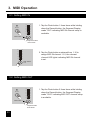
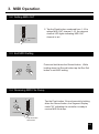
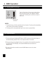
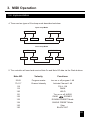
1
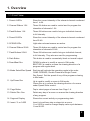
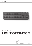
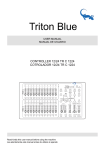
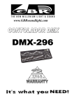
English
American DJ
R
SCENE SETTER-48
48CH Dimmer Console
USER'S MANUAL
SCENE SETTER-48
1
2
3
4
5
6
7
8
9
10
11
12
13
14
15
16
17
18
19
20
21
22
23
48CH Dimmer Console
24
REC STEP
PRESET A
10
10
10
10
10
10
10
10
10
10
10
10
10
10
10
10
10
10
10
10
8
8
8
8
8
8
8
8
8
8
8
8
8
8
8
8
8
8
8
8
8
8
8
6
6
6
6
6
6
6
6
6
6
6
6
6
6
6
6
6
6
6
6
6
6
6
4
4
4
4
4
4
4
4
4
4
4
4
4
4
4
4
4
4
4
4
4
4
4
2
2
2
2
2
2
2
2
2
2
2
2
2
2
2
2
2
2
2
2
2
2
2
0
0
0
0
0
0
0
0
0
0
0
0
0
0
0
0
0
0
0
0
0
0
0
DOWN
UP
DELETE
BEAT REV
CHASE REV
DARK
MODE
SELECT
CHNS
EDIT
% OR 0-255
ALL REV
PAGE
ADD
KILL
RECORD
REC
CLEAR
REC
EXIT
SHIFT
STEP
AUDIO
REV ONE
25
26
27
28
29
30
31
32
33
34
35
36
37
38
39
40
41
42
43
44
45
46
47
48
1
2
3
4
5
6
7
8
9
10
11
12
13
14
15
16
17
18
19
20
21
22
23
24
2
DOUBLE
PRESET
B
SINGLE
PRESET
PARK
3
4
MASTER
.1SEC
10
10
10
10
10
10
10
10
10
10
10
10
10
10
10
10
10
10
10
10
10
10
0
8
8
8
8
8
8
8
8
8
8
8
8
8
8
8
8
8
8
8
8
8
8
8
2
6
6
6
6
6
6
6
6
6
6
6
6
6
6
6
6
6
6
6
6
6
6
6
6
4
5s
5s
10s
4
4
4
4
4
4
4
4
4
4
4
4
4
4
4
4
4
4
4
4
4
4
4
4
6
10s
10s
20s
30s
8
1m
2m
10
5m
10m
MINS
30s
1m
2m
5m
MINS
SHOW
MODE
0
0
2
0
2
0
2
0
2
0
2
0
2
0
2
0
2
0
2
0
2
0
2
0
2
0
2
0
2
0
2
0
2
0
2
0
2
0
2
0
2
0
2
0
2
0
A
BLIND
Please read before use
8
6
4
4
2
2
0
0
AUDIO LEVEL
.1SEC
10
8
2
6
10MIN
SPEED
FADE
INSTANT
10
2
10
8
MIX CHASE
HOLD
5MIN
SCENES
10
SINGLE CHASE
SCENES
A
1-48
READY
FOG
MACHINE
INSERT
1
REC SPEED
PRESET B
American DJ
10
R
10
American DJ
R
FADE TIME
10
HEATING
888
DIMMER
SPEED TIME
.2s
.2s
.2s
.5s
1s
2s
.5s
1s
2s
1s
2s
5s
1m
2m
5m
10m
MINS
SHOW
MODE
B
HOME
TAP SYNC
FULL-ON
BLACK OUT
Contents
Features 1
General Instructions 2
1. Overview 3
1.1 Front View 3
1.2 Rear View 6
2. Operation Guide 7
2.1 Begin Programming 7
2.1.1 Record Enable 7
2.1.2 Security for Your Programs 7
2.1.3 Program Scenes 8
2.2 Editing 11
2.2.1 Edit Enable 11
2.2.2 Erase a Program 12
2.2.3 Erase all Programs 13
2.2.4 Clear a Scene or Scenes 13
2.2.5 Delete a Step or Steps 14
2.2.6 Insert a Step or Steps 15
2.2.7 Modify a Step or Steps 17
2.3 Running 18
American DJ
R
SCENE SETTER-48
48CH Dimmer Console
Improvement and changes to
specifications, design and this
manual, may be may at any time
without prior notice.
All rights reserved.
2.3.1 Running Chase Programs 18
2.3.2 Running a Program To Audio 19
2.3.3 Running a Program With the
Speed Slider 20
2.3.4 Running a Program With the
Standard Beat 21
2.4 Change the Speed Mode between
5 Minutes and 10 Minutes 22
3. MIDI Operation
23
3.1 Setting MIDI IN 23
3.2 Setting MIDI OUT 23
3.3 Exit MIDI Setting 24
3.4 Receiving MIDI File Dump 24
3.5 Sending MIDI File Dump 25
3.6 Implementation 25
Brief of Main Functions 27
Technical Specifications 30
Features
Thank you for your purchase. This product
features include:
Digital Technology Adopted.
As a stage light controller, the unit can control intelligent unit and ordinary light.
Power Failure Memory.
Automatically recover to the last condition when you turn on the machine.
Standard MIDI and DMX ports.
Conveniently connect with other units and machines.
Powerful Program Edit.
You could edit different program according to your needs. The program
could contain 4600 steps utmost and up to 96 programs could be stored.
Various Running Type.
You can run the SCENE with Audio, Speed Slider, Standard beat etc.
More programs can run synchronously.
You can run more programs in Single Mode or Mix Mode simultaneously
1
General Instructions
Read the instruction in this manual carefully and thoroughly, as they give important
information regarding safety during use and maintenance. Keep this manual with
the unit, in order to consult it in the future. If the unit is sold or given to another
operator, make certain that it always has its manual, to enable the new owner to
read about its operation and re lative instructions.
Warnings
DO NOT make any inflammable liquids, water or metal objects enter the unit.
Should any liquid be spilled on the unit, DISCONNECT the power supply to the unit
immediately.
STOP using the unit immediately In the event of serious operation problems and
either contact your local dealer for a check or contact us directly.
DO NOT open the unit--there are no user serviceable parts inside.
NEVER try to repair the unit yourself. Repairs by unqualified people could cause
damage or faulty operation. Contact your nearest dealer.
Cautions
This unit is NOT intended for home use.
After having removed the packaging check that the unit is NOT damaged in any way.
If in doubt, DON'T use it and contact an authorized dealer.
Packaging material (plastic bags, polystyrene foam, nails, etc.) MUST NOT be left
within children's reach, as it can be dangerous.
This unit must only be operated by adults. DO NOT allow children to tamper or play
with it.
NEVER use the unit under the following conditions:
In places subject to excessive humidity.
In places subject to vibrations or bumps.
In places with a temperature of over 45 C /113 F or less than 2 C/35.6 F.
Protect the unit from excessive dryness or humidity (ideal conditions are between
35% and 80%).
DO NOT dismantle or modify the unit.
2
6
4
2
0
6
4
2
0
8
6
4
2
0
6
4
2
0
2
1
8
26
10
8
8
10
10
10
2
25
1
3
27
3
0
2
4
6
8
10
0
2
4
6
8
10
4
28
4
0
2
4
6
8
10
0
2
4
6
8
10
5
29
5
0
2
4
6
8
10
0
2
4
6
8
10
6
30
6
0
2
4
6
8
10
0
2
4
6
8
10
7
31
7
0
2
4
6
8
10
0
2
4
6
8
10
8
32
8
0
2
4
6
8
10
0
2
4
6
8
10
9
33
9
0
2
4
6
8
10
0
2
4
6
8
10
10
34
10
0
2
4
6
8
10
0
2
4
6
8
10
11
35
11
0
2
4
6
8
10
0
2
4
6
8
10
0
2
4
6
8
10
13
37
13
0
2
4
6
8
10
SCENES
12
36
12
0
2
4
6
8
10
0
2
4
6
8
10
14
38
14
0
2
4
6
8
10
0
2
4
6
8
10
15
39
15
0
2
4
6
8
10
0
2
4
6
8
10
16
40
16
0
2
4
6
8
10
0
2
4
6
8
10
17
41
17
0
2
4
6
8
10
0
2
4
6
8
10
18
42
18
0
2
4
6
8
10
0
2
4
6
8
10
19
43
19
0
2
4
6
8
10
0
2
4
6
8
10
20
44
20
0
2
4
6
8
10
0
2
4
6
8
10
21
45
21
0
2
4
6
8
10
0
2
4
6
8
10
22
46
22
0
2
4
6
8
10
0
2
4
6
8
10
23
47
23
0
2
4
6
8
10
0
2
4
6
8
10
24
48
24
DOWN
PRESET
PRESET
8
10
2
0
25
6
3
19 26
24
BLIND
27
HOME
B
4
4
A
2
6
0
PARK
B
SCENES
REC SPEED
MODE
SELECT
8
10
SINGLE
UP
CHASE REV
MASTER
DOUBLE
A
1-48
CHNS
DARK
BEAT REV
FADE TIME
SPEED TIME
DIMMER
REC STEP
3
PAGE
2
4
FADE
STEP
REC
EXIT
ADD
KILL
FULL-ON
1m
2m
28
31
TAP SYNC
5m
10m
MINS
29
10s
1m
2m
5m
10m
MINS
SHOW
MODE
20s
1s
2s
5s
5s
.2s
.2s
30s
1m
2m
5m
MINS
SHOW
MODE
.5s
1s
2s
10s
5s
.5s
1s
2s
30s
.2s
10s
0
2
4
6
8
0
2
4
6
8
10
30
BLACK OUT
10
AUDIO LEVEL
AUDIO
SHIFT
RECORD
ALL REV
EDIT
FOG
MACHINE
READY
HEATING
10MIN
.1SEC
SPEED
.1SEC
5MIN
MIX CHASE
HOLD
INSERT
% OR 0-255
SINGLE CHASE
REC
CLEAR
INSTANT
1
REV ONE
DELETE
888
48CH Dimmer Console
SCENE SETTER-48
34
American DJ
7
6
4
5
3
2
R
American DJ
1
PRESET A
PRESET B
8 9 10 11 12 13 14 15
32
33
23
22
17
18
20
21
16
1. Overview
1.1 Front View
R
1. Overview
1.1 Front View
1. Preset A LEDs
Show the current intensity of the relevant channel numbered
from 1 to 24.
2. Channel Sliders 1-24
These 24 sliders are used to control and /or program the
intensities of channels 1-24.
3. Flash Buttons 1-24
These 24 buttons are used to bring an individual channel,
to full intensity.
4. Preset B LEDs
Show the current intensity of the relevant channel numbered
from 25-48.
5. SCENE LEDs
Light when relevant scenes are active.
6. Channel Sliders 25-48
These 24 sliders are used to control and /or program the
intensities of channels 25-48.
7. Flash Buttons 25-48
These 24 buttons are used to bring an individual channel,
to full intensity. They also are used for programming.
8. Dark Button
This button is used to momentarily black out overall output.
9. Down/Beat Rev
DOWN functions to modify a scene in Edit mode;
BEAT REV is used to reverse the chasing direction of a
program with regular beat.
10. Mode Select/Rec Speed Each tap will activate the operating mode in the order:
CHNS /SCENES, Double Preset and Single Preset.
Rec Speed: Set the speed of any of the programs chasing
in Mix mode.
11. Up/Chase Rev
Up is used to modify a scene in Edit mode.
Chase Rev is to reverse the chasing direction of a scene
under Speed Slider control.
12. Page Button
Tap to select pages of scenes from Page 1-4.
13. Delete/ Rev One
Delete any step of a scene or reverse the chasing direction
of any program.
14. Segment Display
Shows the current activity or programming state.
15. Insert / % or 0-255
Insert is to add one step or steps into a scene.
% or 0-255 is used to change display value cycle between
% and 0-255.
4
1. Overview
1.1 Front View
16. Edit / All Rev
Edit is used to activate Edit mode.
All Rev is to reverse the chasing direction of all programs.
17. Add or Kill/ Rec Exit
In Add mode, multiple scenes or Flash buttons will be on
at a time.
In Kill mode, pressing any Flash button will kill any other
scenes or programs.
Rec Exit is used to exit from Program or Edit mode.
18. Record/ Shift
Record is used to activate Record mode or program a step.
Shift functions only used with other buttons.
19. Master A Button
Brings channel 1-12 to full of current setting.
20. Park Button
Used to select Single/Mix Chase, bring Channel 13-24 to
full of current setting, or momentarily program a scene into
Master B slider, depending on the current mode.
21. Hold Button
This button is used to maintain current scene.
22. Step Button
This button is used to go to next step when the Speed Slider
is pushed to the bottom or in Edit mode.
23. Audio Button
Activates audio sync of chase and audio intensity effects.
24. Master Slider A
This slider controls overall output of all channels.
25. Master Slider B
This slider controls the chase of all programs.
26. Blind Button
This function takes the channel out of the chase of a program
in CHNS /SCENE mode.
27. Home Button
This button is used to deactivate the Blind.
28. Tap Sync Button
Repeatedly tapping this button establish the chase speed.
29. Full On Button
This function bring overall output to full intensity.
30. Black Out Button
This button is used to kill all output with exception for that
resulting from Flash and Full On.
31. Fade Time Slider
Used to adjust the Fade Time.
32. Speed Slider
Used to adjust the chase speed.
33. Audio Level Slider
This slider controls the sensitivity of the Audio input.
34. Fog Machine button
5
1. Overview
1.2 Rear View
POWER
DC INPUT
DMX OUT
MIDI
+
ON OFF
1=Ground
2=Data
3=Data +
2
DC 12V~20V
500mA min.
35
THRU
36
OUT
1
REMOTE
FOG MACHINE
1/4"stereo jack
LINE INPUT
Full on
IN
3
37
AUDIO
1=Ground
2=Data +
3=Data
38
DMX Polarity Select
39
100mV~1Vp-p
Stand By
or Black Out
40
41
GND
42
35. Power Switch
This switch controls turning on or off of the power.
36. DC Input
DC 12-20V, 500 mA Min.
37. MIDI Thru/Out/In
MIDI ports for connection to a sequencer or MIDI device.
38. DMX Out
This connector sends your DMX value to the DMX fixture
or DMX pack.
39. DMX Polarity Select
Used to select DMX polarity.
40. Audio Input
This jack accepts a line level audio input signal ranged
from 100mV to 1Vpp.
41. Remote Input
Black Out and Full On may be controlled by a remote
control using a standard 1/4"stereo jack.
42. Fog Machine Connector
6
2. Operation Guide
2.1 Begin Programming
2.1.1 Record Enable
RECORD
+
1
6
6
8
1. Press and hold down the Record button.
2. While holding down the Record button, tap the Flash buttons 1, 6, 6 and 8
in sequence.
3. Release the Record button, the Record LED lights up, now you can begin
programming your chase patterns.
NOTE:
The first time you turn on your unit, the default setting of the Record Code is
Flash buttons 1, 6, 6 and 8.
You may change the Record Code to protect your programs.
2.1.2 Security for Your Programs
To protect your programs from any editing by others, you may change the
Record Code.
1. Enter current Record Code(Flash buttons 1, 6, 6 and 8).
2. Press and hold down the Record and Edit buttons at a time.
7
2. Operation Guide
2.1.2 Security for Your Programs
3. While holding the Record and Edit buttons, tap the desired Flash button to
enter a new Record Code
The Record Code consists of 4 Flash buttons(the same button or different buttons),
be sure your new Record Code consists of 4 Flash buttons.
4. Enter your new Record Code a second time, all channel LEDs and scene LEDs
will flash three times, now the Record Code is changed.
5. Exit Record mode. Tap the Rec Exit button while pressing and holding down the
Record button, release the two buttons at a time, the Record mode is disengaged.
IMPORTANT!!!
Always remember to exit Record mode when you won't continue
your programming, otherwise you may lose control of your unit.
NOTE:
The second time you enter your new Record Code different from that of the
first time, the LEDs will not flash, which means you've failed to change the
Record Code.
When you've entered a new Record Code the first time, and now you want to
cancel the new Record Code, you may press and hold down the Record and
Exit buttons at a time to exit.
2.1.3 Program Scenes
1. Record Enable.
MODE
SELECT
CHNS
A
SCENES
DOUBLE
PRESET
1-24 SINGLE
PRESET
B
2. Select the 1-48 Single mode by tapping the
the Mode Select button. This will give you
control of all 48 channels as you program.
Be sure that Master A & B are both set at
maximum.
(Master A is at its maximum in the fully up
position , while Master B is at its maximum
in the fully down position.)
8
2. Operation Guide
2.1.3 Program Scenes
1
2
10
10 10
10
8
8
8
8
6
6
6
6
4
4
4
4
2
2
2
2
0
0
0
0
3. Create a desired scene using Channel Sliders
1-48. At 0% or DMX 0, these sliders should be
at 0 position, and at 100% or DMX 255, these
sliders should be at 10 position.
4. Once the scene is satisfactory, tap the Record
button to program the scene as a step into the
memory.
RECORD
5. Repeat step 3 and step 4 until all desired steps
have been programmed into memory.
You may program up to 1000 steps into memory.
1
2
3
PAGE
9
4
6. Select a chase bank or scene master to store
your program. Tap the Page button to select a
page(Page 1-4) to store your scenes.
2. Operation Guide
2.1.3 Program Scenes
10
10
8
8
6
6
4
4
2
2
0
0
RECORD
7. Press a Flash button between 25-48 while
holding down the Record button. All LED
will flash indicating the scenes have been
programmed into memory.
FLASH 25-48
RECORD
8. You can continue programming or exit.
To exit Program mode, tap the Exit button
while holding down the Record button, the
Record LED should go out.
REC
EXIT
EXAMPLE: Program a 16 steps chase with channel 1-32 at full in
sequence into Flash button 25 of Page 1.
1. Record enable.
2. Push Master A & B to maximum position and Fade slider to top.
3. Tap the Mode Select button to select 1-48 Single mode.
4. Push Channel slider 1 to the top position, its LED light at full intensity.
5. Tap the Record button to program this step into memory.
6. Repeat steps 4 and 5 until you've programmed Channel sliders 1-32.
7. Tap the Page button causing Page 1 LED lights.
8. Tap the Flash button 25 while holding down the Record button, all LEDs
will flash indicating you've programmed the chase into memory.
10
2. Operation Guide
2.2 Editing
2.2.1 Edit Enable
1. Record enable.
1
2
3
2. Use the Page button to select the page the
program you wish to edit is on.
4
PAGE
MODE
SELECT
CHNS
A
SCENES
DOUBLE
PRESET
1-24 SINGLE
PRESET
EDIT
11
3. Tap the Mode Select button to select
CHNS
SCENES.
B
4. Press and hold down the Edit button.
2. Operation Guide
2.2.1 Edit Programs
EDIT
10
10
8
8
6
6
4
4
2
2
0
0
5. While holding down the Edit button, tap the
Flash button that corresponds to the program
you wish to edit.
FLASH 25-48
6. Release the Edit button, the relevant scene
LED should light indicating you are in the
Edit mode.
2.2.2 Erase a Program
1. Record enable.
1
2
3
2. Use the Page button to select the page the
program you wish to erase is on.
4
PAGE
EDIT
FLASH 25-48
10
10
8
8
6
6
4
4
2
2
0
0
3. While holding down the Edit button, tap the
Flash button(25-48) twice.
4. Release the two buttons ,all LEDs flash,
indicating the program is erased.
Tap this button twice
12
2. Operation Guide
2.2 Editing
2.2.3 Erase All Programs
RECORD
+
1
4
2
3
1. Press and hold the Record button.
2. Tap the Flash buttons 1, 4, 2 and 3 in sequence while holding the Record
button. All LEDs will flash, indicating all programs stored in memory have
been erased.
2.2.4 Clear a Scene or Scenes
1. Record enable.
2. Record a scene or scenes.
RECORD
REC
CLEAR
13
3. If you are not satisfied with the scene or scenes,
you may tap the Rec Clear button while pressing
and holding the Record button, all LEDs will flash,
indicating the scenes have been cleared.
2. Operation Guide
2.2 Editing
2.2.5 Delete a Step or Steps
1. Enter the Edit mode.
2. Tap the Step button to scroll to the step you
wish to delete.
STEP
3. Tap the Delete button when you reach to the
step you wish to delete, all LEDs will flash
briefly indicating the deletion of the step.
DELETE
4. Continue steps 2 and 3 until all the unwanted
steps have been deleted.
RECORD
5. Tap the Rec Exit button while pressing and
holding down the Record button, the Scene
LED goes out, indicating the exit of Edit mode.
REC
EXIT
14
2. Operation Guide
2.2 Editing
2.2.5 Delete a Step or Steps
EXAMPLE: Delete the third step of the program on Flash button 25
on Page 2.
1. Record enable.
2. Tap the Mode Select button to select CHNS
SCENE mode.
3. Tap the Page button until Page 2 LED lights.
4. Tap the Flash button 25 while pressing and holding down the Edit button, the
Scene LED lights.
5. Tap the Step button to scroll to the third step.
6. Tap the Delete button to delete the step.
7. Tap the Rec Exit button while pressing and holding down the Record button
to exit Edit mode.
2.2.6 Insert a Step or Steps
1. Record a scene or scenes you wish to insert.
2. Be sure you're in CHNS
Enter the Edit mode.
STEP
15
SCENE and
3. Tap the Step button to scroll to the step which
you wish to insert before. You may read the step
from the Segment Display.
2. Operation Guide
2.2.6 Insert a Step or Steps
INSERT
4. Tap the Insert button to insert the step you've
created before, all LEDs will flash, indicating
the step is inserted.
5. Exit Edit mode.
EXAMPLE: Insert a step with channels 1-12 fully on at a time between
step 4 and step 5 of program 35.
1. Record enable.
2. Push Channel sliders 1-12 to the top and record the scene as a step.
3. Tap the Mode Select button to select CHNS
SCENE mode.
4. Tap the Page button until Page 2 LED lights.
5. Tap the Flash button 35 while holding down the Edit button, the corresponding
scene LED lights.
6. Tap the Step button to scroll to the step 4.
7. Tap the Insert button to insert the scene you've created before .
16
2. Operation Guide
2.2 Editing
2.2.7 Modify a Step or Steps
1. Enter Edit mode.
2. Tap the Step button to scroll to the step you wish
to modify.
STEP
3. Press and hold the Up button if you want to raise
the intensity.
If you want to lower the intensity, press and hold
down the Down button.
UP
UP
10
10
8
8
6
6
4
4
2
2
0
0
4. While holding down the Up or Down button, tap
the Flash button corresponding to the DMX
channel of the scene you wish to modify until
you reach the desired intensity value read from
the Segment Display. Then you may tap the
Flash buttons until you are satisfied with the
new scene.
5. Repeat steps 2, 3 and 4 until all the steps have
been modified.
6. Exit Edit mode.
17
2. Operation Guide
2.3 Running
2.3.1 Running Chase Programs
MODE
SELECT
1. Tap the Mode Select button to select CHNS
SCENE mode indicated by the red LED.
CHNS
A
SCENES
DOUBLE
PRESET
1-24 SINGLE
PRESET
1
2
3
B
2. Tap the Page button to select the correct page
the program you wish to run is located.
4
PAGE
MASTER
10
0
8
2
6
4
4
6
2
8
0
10
A
3. Push Master Slider B to its maximum
position(fully down).
B
18
2. Operation Guide
2.3.1 Running Chase Programs
10
10
8
8
6
6
4
4
2
2
0
0
10
10
8
8
6
6
4
4
2
2
0
0
4. Move the desired Channel slider (25-48) to its
maximum position to trigger the program, and
the program will fade in depending upon current
fade time.
You may press and hold down the relevant Flash
button(25-48) to trigger the program.
5. Move the Channel slider to adjust the output
of the current program.
2.3.2 Running a Program To Audio
1. Use built-in microphone or plug the audio source
into the RCA Audio jack.
2. Select your program as described above.
AUDIO
3. Tap the Audio button until its LED lights, indicating
Audio mode is active.
19
2. Operation Guide
2.3.2 Running a Program To Audio
AUDIO LEVEL
10
10
8
8
6
6
4
4
2
2
0
0
4. Use the Audio Level slider to adjust the music
sensitivity.
5. To return to normal mode, tap the Audio button
a second time causing its LED goes out, the
Audio mode is disengaged.
AUDIO
2.3.3 Running a Program With the Speed Slider
1. Be sure the Audio mode is disengaged, that
is, the Audio LED goes out.
2. Select your program as described above.
REC SPEED
FLASH 13-24
10
10
8
8
6
6
4
4
2
2
0
0
3. Move the Speed slider to the SHOW MODE
position(the bottom), then tap the Flash button
(25-48) while pressing and holding down the
Rec Speed button, the corresponding program
will not run with the Standard beat any longer.
20
2. Operation Guide
2.3.3 Running a Program With the Speed Slider
5MIN
10MIN
4. Now you may move the Speed Slider to select
your desired speed.
SPEED
.1SEC
.1SEC
.2s
.2s
.5s
1s
1s
2s
2s
5s
5s
10s
20s
30s
1m
10s
1m
2m
5m
MINS
SHOW
MODE
2m
5m
10m
MINS
SHOW
MODE
NOTE:
The step 3 is not necessary if the selected program
is not recorded with the Standard Beat.
2.3.4 Running a Program With the Standard Beat
1. Be sure the Audio is disengaged. Tap the Mode
Select button to select CHNS
SCENE mode.
SINGLE CHASE
MIX CHASE
PARK
2. Tap the Park button to select Mix Chase mode,
the LED lights indicating this selection.
3. Select your program as described above.
5MIN
10MIN
SPEED
.1SEC
.1SEC
.2s
.2s
.5s
1s
1s
2s
2s
5s
5s
10s
30s
1m
2m
5m
MINS
SHOW
MODE
21
4. Move the Speed slider until the Segment Display
reads your desired value.
10s
20s
1m
2m
5m
10m
MINS
SHOW
MODE
You may tap the Tap Sync button twice to define
your beat time.
2. Operation Guide
2.3.4 Running a Program With the Standard Beat
REC SPEED
10
10
8
8
6
6
4
4
2
2
0
0
5. While pressing and holding down the Rec
Speed button, tap the Flash button(25-48) that
stores the program.
6. The program will then run with the set time or
beat when engaged.
FLASH BUTTONS 25-48
7. Repeat steps 4 and 5 to set a new beat time.
2.4 Change the Speed Mode between 5 Minutes and 10 Minutes
1. Press and hold the Record button.
RECORD
RECORD
10
10
8
8
6
6
4
4
2
2
0
0
2. Tap the Flash button 5 or 10 three times
while holding down the Record button.
Flash Button 5 or 10
Tap this button
three times
3. The 5MIN or 10MIN should light up indicating
the Speed slider is set to run in the 5 or 10
minute mode.
22
3. MIDI Operation
3.1 Setting MIDI IN
RECORD
10
10
8
8
6
6
4
4
2
2
0
0
1. Tap the Flash button 1 three times while holding
down the Record button, the Segment Display
reads "CHI" indicating MIDI IN channel setup is
available.
Flash button 1
Tap this button
three times
10
10
8
8
6
6
4
4
2
2
0
0
2. Tap the Flash button numbered from 1-16 to
assign MIDI IN channel 1-16, the relevant
channel LED lights indicating MIDI IN channel
is set.
Flash buttons
1-16
3.2 Setting MIDI OUT
RECORD
10
10
8
8
6
6
4
4
2
2
0
0
Flash button 2
Tap this button
three times
23
1. Tap the Flash button 2 three times while holding
down the Record button, the Segment Display
reads "CHO" indicating MIDI OUT channel setup
is available.
3. MIDI Operation
3.2 Setting MIDI OUT
10
10
8
8
6
6
4
4
2
2
0
0
2. Tap the Flash button numbered from 1-16 to
assign MIDI OUT channel 1-16, the relevant
channel LED lights indicating MIDI OUT
channel is set.
Flash buttons
1-16
3.3 Exit MIDI Setting
Press and hold down the Record button. While
holding down the Record button tap the Rec Exit
button to exit MIDI setting.
RECORD
REC
EXIT
3.4 Receiving MIDI File Dump
RECORD
10
10
8
8
6
6
4
4
2
2
0
0
Tap the Flash button 3 three times while holding
down the Record button, the Segment Display
reads "IN" indicating the controller is ready to
receive MIDI file dump.
Flash button 3
Tap this button
three times
24
3. MIDI Operation
3.5 Sending MIDI File Dump
RECORD
10
10
8
8
6
6
4
4
2
2
0
0
Tap the Flash button 4 three times while holding
down the Record button, the Segment Display
reads "OUT" indicating the controller is ready to
send a file.
Flash button 4
Tap this button
three times
NOTE:
1. During file dump, all other operations will not function. Functions will automatically
return when the file dump is completed.
2. File dump will be interrupted and stop if errors occur or power failure.
3.6 Implementation
1. During receiving and sending MIDI data, all MIDI scenes and channels being run
will automatically paused if there is no response within 10 minutes.
2.During receiving and sending file dump, the controller will automatically search for
or send Device ID of 55H(85), a file named DC2448 with an extension of
"BIN(SPACE)".
3.File dump allows this controller to send its MIDI data to next unit or other
MIDI devices.
25
3. MIDI Operation
3.6 Implementation
4. There are two types of file dump mode described as below:
Open Loop Mode
CONTROLLER
MIDI OUT
RECEIVER
MIDI IN
MIDI OUT
MIDI IN
Close Loop Mode
CONTROLLER
MIDI OUT
RECEIVER
MIDI IN
MIDI OUT
MIDI IN
5. The controller will send and receive Note On and Note Off data via the Flash buttons.
Note NO.
Velocity
Functions
22-69
70-117
118
119
120
121
122
123
124
Program master
Channel intensity
turn on or off program 1-48
Activate Channel 1-48
FULL -ON
DARK
HOLD
Turn on or off AUDIO
CHNS
SCENES
DOUBLE PRESET Mode
SINGLE PRESET Mode
Step
BLACK OUT
125
126
26
4. Brief of Main Functions
Reverse the direction of the scene
1. Reverse the direction of all the scenes:
Press the ALL REV Button, all the scenes should change their directions.
2. Reverse the chasing direction of all the programs with speed control.
Press the Chase Rev Button.
3. Reverse the chasing direction of all the programs with standard beat:
Press the Beat Rev Button.
4. Revers chasing direction of any program:
Press and hold down the Rec One Button, then press down the Flash Button
corresponding to your desired program and release together.
Fade Time
1. The amount of time it will take for the dimmer to go from zero output to maximum
output, a nd vice verse.
2. Fade time is adjusted through the Fade Time Slider, which varies from instant to
10 minutes.
Tap Sync Button:
1. The Tap Sync button is used to set and synchronize the chase rate (the rate at which
all scenes will sequence) by taping the button several times. The chase rate will synchronize
to the time of the last two taps. The LED above the Step Button will flash at the new chase
rate. The chase rate may be set anytime whether or not a program is running.
2. Tap Sync will override any previous setting of the speed slider control until the slider is
moved again.
3. Use of Tap Sync in setting a standard beat is the same with speed control slider.
Master Slider
Master Slider control provides proportional level control over all channels and scenes
with the exception of the Flash Buttons. For example:
Whenever the Master slider control is at minimum all stage outputs will be at zero except
for any resulting from a Flash Button or FULL ON Button.
If the Master is at 50%, all outputs will be at only 50% of the setting of current channel
or scenes except for any resulting from a Flash Button or FULL ON Button.
If the Master is at full all outputs will follow the unit setting.
Master A always controls outputs of channels. Master B controls the program or a scene
except in Double Preset Mode.
27
4. Brief of Main Functions
Single Mode
1. All programs will run in sequential order starting in the order of program number.
2. The Segment Display will read the running program number.
3. All programs will be controlled by the same Speed Slider .
4. Press the MODE SELECT BUTTON and select " CHNS
SCENES".
5. Press the PARK BUTTON to select SINGLE CHASE MODE. A red LED
will indicate this selection.
Mix Mode
1. Will run all programs synchronously.
2. All programs can be controlled by the same SLIDER SPEED, or each programs
speed may be controlled individually. (See Speed Setting ).
3. Press the MODE SELECT BUTTON and select "CHNS
SCENES".
4. Press the PARK BUTTON to select MIX CHASE MODE. A yellow LED will
indicate this selection.
Dimmer Display
1. The 3-Digit Segment Display is used to display intensity percentage or absolute
DMX value.
2. To change between percentage and absolute value:
Press and hold the Shift Button. While holding down the Shift button press the
% or 0-255 Button to switch between percentage and absolute values.
3. If the Segment Display reads, for example, "076", it means a percentage value 76%.
If the Segment Display reads "076.", it means the DMX value 76.
Blind and Home
1. Blind function takes channels temporally out from a chase, when the chase is running,
and gives you manual control over the channel.
2. Press and hold the Blind Button and tap the relative Flash Button you want to temporarily
take out of the chase.
3. To return to normal chase again press and hold the Home Button and push the Flash
Button you want to return to normal chase.
28
4. Brief of Main Functions
Park
1. In CHNS
SCENES Mode, press down the button you can change the chasing
mode of programs between Single Mode and Mix Mode.
2.In Double Preset Mode, pressing down this button is equal to pushing Master Slider B
to the top.
3.In Single Preset Mode, this button could temporally record current output, with
Master Slider B to adjust.
Add and Kill
The ADD/KILL Button changes the mode of the flash buttons. Normally the flash buttons
are in Add mode, whereas pressing any flash button will not kill other scenes, allowing
multiple scenes to be on at a time.
The Kill mode is activated by pressing the Add/Kill button and illuminating the LED
above it. Pressing any flash button will kill other active SCENE or Program.
In Kill Mode, the killed program does not stop running but can not output.
Double Preset
1. Press Mode Select Button to enter A Double Preset Mode.
2. In this
. mode, Channel Sliders 1-24 and channel sliders 25-48 both control Channel
1-24.
3. Master A controls channel Slider 1-24 while Master B controls Channel Sliders 25-48.
4. In this Mode, no scene could be recorded.
Example
1. Enter the Double Preset Mode.
2. Push Channel Sliders 1 to 6 to the top and move Channel Sliders 19 to 24 to the
maximum.
3. Move Master A and B to the same level and push them to the same direction, you
will get a scene.
29
Technical Specifications
Power Input .............................................. DC 12~20V, 500 mA min.
DMX Output .......................................................... 3 pin female XLR
MIDI Signal ................................................. 5 pin standard interface
Audio Input ................................................................ 100 mV~1Vpp
Fuse(internal) .................................................. F0.5A 250V 5x20mm
Dimensions .............................................................. 711x264x85mm
Weight(appro.) ........................................................................ 7.2 kg
Attention!
1. To retain your programs from loss, this unit must be powered not less
than two hour every month.
2. The Segment Display shows "LOP" if the voltage is too low.
30
ALL RIGHTS RESERVED
Rev 1.1 Nov., 2000
American DJ
R
24-004-0337
Web Site: www.americandj.com