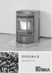
Download RIKA INTEGRA II Instruction manual
Transcript
INTEGRA II
Instruction Manual
-1-
-2-
22
Fig. 3
-3-
-4-
CONTENTS
Technical specification and spare parts overview
7
1.
IMPORTANT INFORMATION
8
2.
WHAT ARE PELLETS?
Specification for high-quality pellets
Pellet storage
8
8
8
3.
TECHNOLOGY
9
4.
AUTOMATIC SAFETY FUNCTIONS
Power failure
Overheating
Low temperature switch off
Electrical excess current switch off
5.
6.
7.
8.
9.
9
9
9
9
INSTALLING THE STOVE
General information
Making the chimney connection
Method
Floor protection
Safety distances
Electrical connection
Combustion air
Feed of external combustion air
10
10
10
10
11
11
11
11
FITTING THE PANELLING, OPTIONS
General
Side panel
Control and operating board
12
12
12
OPERATION
Basic information
Control and internal control unit – function
Internal control unit
13
13
13
UNIT COMMISSION ING/CONTROL
PROGRAMMING/CONTROL OPTIONS
General
First commissioning/program settings
Main menu operating areas
Shut down unit
Shut down from “Manual operation (ON)”
Shut down unit from automatic operation
Automatic stop controlled by heating time
Automatic stop, manual
Shut down by operating mode in Standby
Pellet control (optional) room temperature sensor
Tele-Control (telephone control optional)
14
14
17
17
17
19
19
19
19
19
19
ELECTRICAL IGNITION
Pre-heating without electrical ignition
Some field values
Fuel feed
20
20
20
-5-
10. CLEANING AND MAINTENANCE
Basic Information
Cleaning the fire tray
Cleaning the grate door glass
Cleaning the flue gas channels
Cleaning exhaust gas collector
Cleaning exhaust gas fan housing
Cleaning pellet container
Inspecting door seal
Checking chimney connection
Cleaning air sensor
21
21
22
22
22
23
23
23
23
23
11. FAULTS – CAUSES - SOLUTIONS
Error messages control
24
12. ATTACHMENT
Navigation to programme the internal control system
26
13. LIST OF HEADINGS AND ABBREVIATIONS
27
14. WARRANTY
We guarantee
Warranty card
29
32
Subject to technical and visual changes; setting and printing errors excepted.
EXPLANATION OF SYMBOLS
Important information
Practical advice
Use the plan
-6-
SPARE PARTS - OVE RVIEW
(Fig. 1)
(Fig. 2 - Fig. 5)
TECHNICAL DATA
Height
Width
Depth of the corpus
Weight without casing
Flue pipe outlet diameter
Heat output range
Room heating capacity (m3)
depending on house insulation
Fuel consumption
Pellet container capacity
Mains connection
Average electrical power
consumption
Protection
Efficiency
CO2 content
CO emission rel. 13% O
Dust emissions
Exhaust mass flow
Exhaust temperature
Draught requirement
DESCRIPTION
[mm]
[mm]
[mm]
[kg]
[mm]
[kW]
950
724
652
155
100
2,5 - 9
[m3]
50 - 240
[kg/h]
[kg]
[V]; [Hz]
0,7 – 2,2
62
230/50
[W]
< 100
[A]
[%]
[%]
[mg/Nm3]
[mg/Nm3]
1.6 T
85,7
8,8
136
22
[g/s]
[°C]
[Pa]
9,2
178
0
01 Glass ceramic side
02 Glass ceramic front
03 Cast iron door
04 Screw handle
05 Door handle
06 Conveyor auger cover
07 Heat guard
08 Cleaning lid incl. seal
09 Conveyor helix
10 Motor plate
11 Auger drive motor
12 Gear guard
13 Container lid
14 Lid ceramic
15 Lid plate
16 Air sensor
17 Decorative ring
18 Ash pan
19 Combustion chamber
21 Flue plate bottom
22 Insulation plate
23 Flue plate top
24 Excess temperature switch
25 Edge plate of door welded
27 Main board
28 Tele-Control (optional)
29 Mains cable
30 Adapter for flue gas fan
31 Locking ring
32 Low temperature switch
33 Seal for low temperature switch
34 Flue gas fan - blower complete
35 Flue gas fan motor with Hall IC
36 Convection fan
37 Hinge top
38 Hinge bottom
39 Heating element for electric ignition
40 Assembly tube for heating element
41 Side cladding left
42 Cladding left back
43 Base
44 Cladding right back
45 Control board
46 Side cladding right
47 Cover
The owner of the small heating system or the
authorised person for the small heating system must
keep the technical documentation in a safe place
and present it to the local authority or the chimney
sweep if required.
1. PACKAGING
Your first impression is important to us!
The packaging for your new stove provides excellent
protection against damage. However damage to the
stove and accessories can occur during transport.
Therefore please check that your stove is undamaged
and that all parts are there on receipt!
- The packaging for your new stove generally has no
effect on the environment. The box and the film (PE)
can be safely taken to the local council waste
disposal depot for recycling.
Please observe the national and European
standards as well as local regulations
concerning the installation and operation of
firing installations!
-7-
ENGLISH
TECHNICAL SPECIFICATION
ENGLISH
1. IMPORTANT INFORMATION
● Make children aware of the danger and keep
them away from the stove when in use.
GENERAL WARNING AND SAFETY
INSTRUCTIONS
● Placing non heat resistant objects on the stove or
nearby is prohibited.
The general introductory warning information must
be followed.
● Do not lay washing on the stove to dry.
● Read the whole of the manual thoroughly before
commissioning the stove.
● Stands for drying items of clothing or suchlike
must be set up at an adequate distance from the
stove – fire hazard!
● Only approved transport aids with adequate load
bearing capacity must be used for transporting your
stove.
● When your stove is burning, the use of highly
inflammable and explosive materials in the same or
adjacent rooms is prohibited.
● Your stove is not suitable for use as a ladder or
scaffold.
● ATTENTION!!
In cause of safety reason please do not open the
combustion chamber door during operation!
● The burning of fuel releases heat energy that
leads to extensive heating of the stove surfaces,
doors, door and operating handles, glass, flue pipes
and possibly the front wall. Refrain from touching
these parts without appropriate protective clothing or
equipment e.g. heat-resistant gloves or means of
operation (operating handle)
● CAUTION when filling the storage container.
The opening of the pellet container is sufficient to
ensure problem-free filling. Ensure that no pellets
fall on the convection ribs and the hot stove body.
This can otherwise lead to heavy smoke formation.
We therefore recommend refilling the storage
container when the stove is cold.
-8-
Wood pellets are a standardised fuel. Every
manufacturer must adhere to certain conditions in
order to enable flawless, energy-efficient heating.
Pellets are made from wooden waste, from sawmills
and planning workshops, as well as from residue
from forestry operations. These “starting products”
are crushed, dried, and pressed into Pellet “Fuel”
without any bonding agent.
are reviewed every year. A quality assurance
system ensures the pellets comply with the
requirements of the new standard and that the
conditions for trouble-free heating are guaranteed.
Please request tested fuel and a list of monitored fuel
manufacturers from your pellet stove dealer.
Use of poor quality or non-approved pellet fuel impairs
the function of your stove and may lead to lapsing of
the warranty, guarantee and associated product
liability. Observe the ban on incinerating waste!
Only burn pellets that have been inspected according
to ÖNORM, DIN Plus or ENplus-A1.
ENplus – Pellets
This new pellets are a standard sets new
benchmarks in the European pellet market. The
traceability of pellets is ensured thanks to the use of
identification numbers. The pellet manufacturers’
production facilities and manufacturing processes
WOOD PELLET SPECIFICATION according to ENplus – A1
Parameter
Diameter
Length
Bulk density
Calorific value
Water content
Fine fraction (< 3.15 mm)
Mechanical rigidity
Ash content
Ash softening temperature
Chlorine content
Sulphur content
Nitrogen content
Copper content
Chrome content
Arsenic content
Cadmium content
Mercury content
Lead content
Nickel content
Zinc content
1)
2)
3)
4)
Unit
mm
mm
kg/m³
MJ/kg
Ma.-%
Ma.-%
Ma.-%
1)
Ma.-%
(DT) °C
1)
Ma.-%
1)
Ma.-%
1)
Ma.-%
1)
mg/kg
1)
mg/kg
1)
mg/kg
1)
mg/kg
1)
mg/kg
1)
mg/kg
1)
mg/kg
1)
mg/kg
ENplus-A1
2)
6 (±1)
3)
3.15 to 40
≥ 600
≥ 16.5
≤ 10
≤1
4)
≥ 97.5
≤ 0.7
≥ 1200
≤ 0.02
≤ 0.03
≤ 0.3
≤ 10
≤ 10
≤1
≤ 0.5
≤ 0.1
≤ 10
≤ 10
≤ 100
in an anhydrous state
Diameter must be specified
a maximum of 1% of the pellets may be longer than 40 mm; max. length is 45 mm
The limit value of ≥ 97.7 Ma.-% applies when conducting measurements with a Lignotester (internal control)
PELLET STORAGE
In order to guarantee problem free burning of the
wooden pellets, it is imperative necessary to store
the fuel as dry as possible and free from impurities.
NOTE: Waste and liquids may not be burnt in the
stove!
Pellets should not be kept in sacks outdoors or
stored in a manner where they are exposed to the
environment. This can lead to blockages in the
screw conveyor - "screw stoppers" are excluded
from the warranty.
-9-
ENGLISH
2. WHAT ARE PELLETS?
ENGLISH
3. TECHNOLOGY
Your operating outlay is reduced to the most
necessary - this prevents operating faults whilst
working in an optimum fashion at the same time.
Your new pellet stove is technologically advanced
as a result of years of tests in the laboratory and in
practice. The practical advantages of your pellet
stove are convincing:
–
HIGHEST EFFICIENCY - LOWEST
EMISSIONS
The electronic monitoring device together with a
patented “air sensor” controls and regulates the
interplay of flue gas fan, conveyor auger, convection
fan and temperature.
This monitoring system guarantees an optimum
combustion and operating mode.
A very large heat exchanger surface togetherwith
optimum combustion air control leads to very good
fuel usage. Finely metered pellet feed in an
optimised burner pot made from high quality grey
cast iron effects almost perfect combustion with very
good exhaust gas values - and this is guaranteed in
every operating phase.
OPERATING
COMFORT
OPERATIONAL RELIABILITY
4. AUTOMATIC SAFETY FUNCTION
A taking-out-of-service program (cleaning, follow-up
phase) is performed. The stove must be restarted
depending on the pre-set mode.
POWER FAILURE
After a short power failure the operating functions
that were set before the power failure are continued.
ON mode (manual operation). The control switches
to the ST (Start Phase) and the unit then re-runs in
ON operation. TM mode (automatic operation). The
control switches to the ST (Start Phase) and the unit
then re-runs in TM operation. SB mode (operational
readiness, standby operation). After two seconds
the control re-runs in the SB operation.
CAUTION: If overheating has occurred then
maintenance or cleaning work must be carried out.
LOW TEMPERATURE SWITCH OFF
If the stove cools down below a minimum
temperature, then the stove will switch off. This
switch off can also occur if pre-heating is too slow.
On power failure a small amount of smoke may be
shortly emitted. This does not represent a safety
risks.
ELECTRIC
SHUT OFF
OVERHEATING
A temperature safety switch (STL) switches the
stove off automatically if it overheats.
EXCESS-CURRENT
The device is protected against excess current by a
main fuse (on the rear of the device), (see
“Technical Specification”).
- 10 -
GENERAL INFORMATION
MAKING THE CHIMNEY
CONNECTION
The stove must be connected to a chimney that is
approved for solid fuels. The chimney must have a
diameter of at least 120 mm.
The flue system is based on negative pressure in
the combustion chamber and a slight overpressure
on the flue gas outlet. It is therefore important that
the flue gas connection is fitted correctly and is
airtight.
(Fig. 1)
Method
1. Measure and draw the chimney connection
(taking any floor plate thickness into
consideration). (Fig. 1) We recommend
determining the dimension of the flue pipe
discharge directly at the oven.
2. Chisel out (drill) the hole in the wall
3. Brick in the wall lining
4. Connect stove with the flue tube to the
chimney.
Only use heat resistant sealing materials, as well as
the relevant sealing bands, heat resistant silicon and
mineral wool.
Only authorised technical personnel must carry out
assembly work.
FLOOR PROTECTION
In addition you must ensure that the flue tube does
not project into the free cross section of the
chimney.
For flammable floor surfaces (wood, carpet, etc.) a
glass, steel plate or ceramic underlay is required.
NOTE: Please follow the regionally valid building
regulations. Contact your master chimney sweep for
information on this.
Ensure that outlet routes to the chimney are not too
long.
Avoid too many changes of direction for the flue gas
flow to the chimney. (e.g. too many corners and
bends). Don’t exceed a maximum of 3 bends in the
flue pipe.
Where you cannot connect directly to the chimney, if
possible use a connection piece with cleaning
opening.
For optimum efficiency please use the type of
connector we recommend.
SAFETY DISTANCES
(Measured from the outside of the
stove)
From non-combustible objects
a = on the side & back > 100 mm
b = on the front > 400 mm
From combustible objects and to load-bearing walls in
reinforced concrete
a = on the side & back > 200 mm
b = on the front > 800 mm
- 11 -
ENGLISH
5. INSTALLING THE STOVE
ENGLISH
Feed of external combustion air
ELECTRICAL CONNECTION
● Steel, HT or flexible aluminium pipes must be
used.
● Minimum diameter 5 cm/2 inches.
● For longer connection runs the diameter must be
increased to approx. 10 cm after approx. 1 m.
● The pipe should not be longer than approx. 4m
in total to guarantee adequate air feed and not
have too many bends.
● Should the line lead into the open air, it must
end with a vertical 90° downward elbow or with a
wind guard.
The stove is supplied with an approx. 2.5 m long
connecting cable with a plug. The cable must be
connected to a 230 V, 50 Hz electrical supply. The
average electric power consumption is approx 100
watts during heating. During the automatic ignition
process (duration 10 minutes) approx. 350 watts.
The connection cable must be laid so that any
contact with hot or sharpedged external surfaces on
the stove is avoided.
COMBUSTION AIR
Should one or more of these conditions NOT be
applicable then usually poor combustion will occur
in the stove, as well as air underpressure in the
apartment.
Each combustion procedure requires oxygen or air.
As a rule this combustion air is removed from the
living area for individual stoves The air taken from
the living area must be reintroduced. In modern
houses, very tight fitting windows and doors mean
that too little air flows back. This situation becomes
problematic due to additional ventilation in the
house (e.g. in the kitchen or WC). If you cannot feed
in external combustion air, then air the room several
times a day to prevent negative pressure in the
room or poor combustion.
Further it is possible to extract the combustion air
directly from outside or from another room that is
well ventilated (e.g. the cellar).
Please observe:
Your pellet stove works independent of the room air.
Negative pressures in the set-up room are not
permissible. Therefore the use of a safety device
(e.g. differential pressure controller) in combination
with room air facilities (e.g. ventilation system,
exhaust extraction etc.) is stipulated.
The suctioning in of combustion air is performed via
the flue gas blower. The resulting combustion air
and suctioning noises are normal operational noises
that may occur at varying volumes depending on the
chimney draught, output level or a dirty combustion
trough – NOT A CAUSE FOR COMPLAINT!
Note: Please note that problems may arise due to
updrafts in the case of combustion air supply from
an integrated chimney ventilation shaft. If the
combustion air flowing downwards is heated it may
rise and thus counter the chimney with a resistance
which in turn reduces the negative pressure in the
combustion chamber. The chimney manufacturer is
to guarantee that the resistance for the combustion
air is a maximum 2 Pa even in the least favourable
operating state of the chimney.
Minimum diameter
5 cm / 2 inch
Wall
- 12 -
ENGLISH
6. ASSEMBLY OF PANELS, OPTIONS
GENERAL
CAUTION! Only work on the unit when the mains plug
has been disconnected.
Your stove must be switched off and cooled before
any work is performed.
Do not allow objects (screws etc.) to fall into the fuel
container – they can block the screw conveyor and
damage the stove.
SIDE PANEL
1. Insert the side sections in the receiving seat
provided on the bottom section.
2. Push the side section against the stove until it is
vertical.
3. Then fasten with two screws in the pellet
container
Repeat on the other side of the stove.
CONTROL
BOARD
AND
OPERATING
The INTEGRA II pellet stove has an internal
electronic control system located in the stove and
an operating board attached to the stove panels.
Work on the control system (mainboard) and the
operating board may only be performed by trained
specialist dealers or service technicians. Incorrect
handling of these parts leads to loss of warranty.
- 13 -
ENGLISH
7. OPERATION
BASIC INFORMATION
INTERNAL CONTROL UNIT
The stove must only be started when fully fitted.
All settings and functions can be regulated
via this unit.
Your pellet stove is exclusively for burning pellets
made from wood of a controlled quality. Non-pelletised
solid fuels (straw, maize, chopped matter etc.) are not
permitted. Failure to adhere to these guidelines will
make all guarantee and warranty claims null and void
and could have a negative effect on the safety of your
stove.
When operated correctly your pellet stove cannot
overheat. Improper operation can however shorten the
life expectancy of the electric stove components (fan,
motors and electric control) and is not permitted.
CONTROL
AND
INTERNAL
CONTROL UNIT - FUNCTION
Your pellet stove is fitted with a modern
programmable microprocessor control. The user can
preset the individual stove functions via the internal
control unit (keypad with operating display) fitted at
the top of the right hand stove panel.
Fig 1. Internal operating unit, key layout
DISPLAY PANEL:
Display of operating state in illuminated text
The control (main board) and the control board may
only be altered by trained specialist dealers or the
service department. Improper handling of these
parts leads to the guarantee and warranty becoming
null and void.
MENU:
Navigation in and to the various sub-menu levels
ENTER:
Navigation in the main menus (SB, ON, TM) and
confirmation of use inputs
MINUS/PLUS:
Decrease and increase of user values
ON/OFF:
Switching unit on and off
For a graphical representation of the menu
navigation of the program levels see Appendix,
page 29.
- 14 -
Now press “ENTER” and the display shows:
GENERAL
● Check that the pellet container is full and the
combustion chamber is clean and contamination
free.
“S1” = start first heating time, 6 the
number is the time in hours (0 to 23
hours) e.g. see window 6 Hour.
CAUTION: During the ignition process the grate door
must be closed. The electronic ignition does not work
if the grate door is open.
By pressing the “+” or “-” keys the heating time can
be changed in hourly steps as required. The desired
value is confirmed with “ENTER” and is then saved.
The display shows
When the pellet container of the stove is filled for the
first time, no pellets are conveyed to the fire tray for
about 10 minutes. You can put a handful of pellets in
the fire pan to avoid a new start process.
FIRST
COMMISSIONING/
PROGRAMME SETTINGS
“E1” = end of first heating time,
After filling the supply container and connecting the
stove to the mains electrical supply, press the
ON/OFF key on the internal operating unit and SB
(Standby) is displayed.
By pressing the “+” or “-” keys the heating time can
be changed in hourly steps as required. The desired
value is confirmed with “ENTER” and is then saved.
The display shows
“SB” = standby operation
“S2” = start of second heating
time,
Now program your control for your individual
requirements as follows: (See page 29 for menu
navigation). Two heating intervals can be
programmed for each weekday. No heating times
are programmed in the factory. Press “MENU” on
the operating unit and the display shows the
following:
After entering the second heating time
confirming with “ENTER” the display shows
and
“E2” = end of second heating time,
“MO” = Monday
After entering the switch off point of the second
heating time and confirming with “ENTER” the new
valued is saved and the display now shows:
- 15 -
ENGLISH
8. DEVICE COMMISSIONING / CONTROL PROGR AMMING / CONTROLOTIONS
ENGLISH
If you want to maintain a specific heating output (low
operation) between the programmed heating times
you can set the required value by pressing the “+” or
“-” keys.
On selecting the “MENU” key the display shows the
following weekday:
“TU” = Tuesday,
The number equals the heating
output in percent (e.g. see window
5%).
Press the “ENTER” key to return to the starting point
of the first heating time for Tuesday.
Press the “ENTER” key to save the PE value, the
display shows:
Proceed to enter the rest of the heating times for the
weekdays (Wednesday “WE”, Thursday “TH”, Friday
“FR”, Saturday “SA”, Sunday “SU” as described
above.
To improve combustion quality, automatic
cleaning of the fire pan is programmed into the
control process
After acknowledgement with “ENTER” of the E2
value of Sunday (SU) and selection of “MENU” the
display shows:
“CL” = Clean
the number indicates the time
interval in minutes (e.g. see
window 60 Minutes).
“PS” (Power Start) = heating
output during the programmed
heating times (S1-E1, S2-E2).
By pressing the “+” or “-” keys you can determine
the desired time interval in 5 minute steps (The
cleaning interval can be extended to 300 minutes,
however we recommend a cleaning cycle of 60
minutes). Confirm with “ENTER” and the display
shows:
The number corresponds to the heating output in
percent (0% equals minimum heating output, 100%
equals maximum heating output).
By pressing the “+” or “-” keys you can change the
value of the heating output in 5% steps as required.
The value is confirmed with “ENTER” and the
display shows
VA
1.28
“PE” (Power End) = heating
output between the programmed
heating times (E1-S2).
This is the current software version
of the control and is used for
customer service reasons (display
only).
Now use “MENU” to access the internal clock and
the following display appears:
“H” = Hour the number indicates
the hour (value range 0 to 23).
“OFF” indicates that the stove is switched off
between the programmed heating times.
The value “OFF” is achieved by pressing the “-” key
until “OFF” is displayed.
- 16 -
“PN”
The number 8 (see window)
represents the second digit of the
PIN code:
“M” = Minutes, the number
indicates the minutes (value range
0 to 59).
Press the “+” or “-” keys to select the required value
and confirm with “ENTER”, the display then shows:
Set the minutes of the system clock to the correct
value by pressing the “+” or “-” keys and confirm
with “ENTER”. The value is then saved and the
display shows:
“PN”
The number 1 (see window)
represents the third digit of the PIN
code:
“D” = Day, the number indicates
the weekday, e.g. see window 3 =
Wednesday.
Press the “+” or “-” keys to select the
required value and confirm with “ENTER”,
the display then shows:
Set the current weekday (1 = Monday, 2 = Tuesday,
3 = Wednesday, 4 = Thursday, 5 = Friday, 6 =
Saturday, 7 = Sunday) by pressing the “+” or “-”
keys and confirm the new value by pressing
“ENTER”. The value is then saved and on pressing
“MENU” the display shows:
“PN”
The number 5 (see window)
represents the fourth digit of the
PIN code:
a) if the optional Tele-control is installed
Press the “+” or “-” keys to select the required value
and confirm with “ENTER”. Then select “MENU” and
you return to the main menu and the display shows:
“RI” = Rings
The number of ring tones can be
set from 1 to 10.
“SB” = Standby
By pressing the “+” or “-” keys the number of rings
can be changed. Press “ENTER” to confirm and the
value is then saved and the display shows:
Now the stove has been programmed according to
your individual requirements you can set it to
manual mode (ON mode) by a single press on the
“ENTER” key or to automatic mode (TM mode) by
double pressing the “ENTER” key
“PN” means PIN-Code
(Personal Identification Number)
4-digit.
The number 0 (see window) represents the first digit
of the PIN code (0 - 9 possible):
- 17 -
ENGLISH
Select the desired value by pressing the “+” or “-”
keys and confirm with “ENTER”. The display then
shows:
By pressing the “+” or “-” keys the current hour of
the internal clock can be set. The desired value is
confirmed with “ENTER” and is then saved. The
display shows
ENGLISH
Ensure that when the stove is in ON mode the heating
operation starts after 10 seconds. In automatic mode
(TM) the heating process starts in accordance with the
programmed heating times.
MAIN
MENU
RANGES
–
Start manual operation.
The following flashing indicators appear alternately
on the display
OPERATING
According to your requirements you can choose one
of the following three operating types:
● Standby mode
“ST” indicates start
The number below indicates the remaining time for
the start process in minutes.
On completion of the start phase the following
appears continuously on the display
“SB” = Standby Stove is switched
off but remains active for control by
Tele-Control (Telephone).
“ON” = Manual operation
● Manual operation
“ON” = Manual operation The
number equals the heating output
in percent (0% is minimum output
and 100% is maximum heating
output).
If you want to change the current heating output
then you can set the required heating output in 5%
steps (from 0 to 100) by pressing the “+” or “-” keys.
● Automatic operation
“TM” = Automatic operation(Time
mode) The number equals the
heating output in percent (0% is
minimum output and 100% is
maximum heating output.
You can switch between the various operating types
by pressing “ENTER”
- 18 -
PLACE STOVE OUT OF OPERATION
When TM is selected on the display and the
programmed heating time begins the control starts
the heating operation.
Switching off from “Manual operation” (ON)
If the “ON/OFF” key is pressed during operation
then the switch off program is activated. The
following alternating flashing indictors appear on the
display:
The following flashing indications appear alternately
on the display:
“TM” indicates automatic operation.
“Ex” Exit phase 1
The number below is the remaining time in seconds
for this phase.
On completion of the start phase the following
appears continuously on the display
On completion of Exit phase 1 the display shows
(flashing):
Generally the pre-programmed heating output (PS,
PE) is adopted. If however youwant to change the
current value, then this can be done by pressing the
“+” or “-” keys in 5% steps. The changed value
appears on the display. The program adopts the
new value for the control until the completion of the
current heating window. On starting the following
heating time the programmed value is re-used. A
permanent change of heating output can only be
achieved by programming PS and PE.
“CL” Cleaning phase
The number below is the remaining time in seconds
for this phase.
On completion of Exit phase 1 the display shows
(flashing):
Note:
The pre-heating program runs automatically and can
be stopped by changing (“ENTER” key) the operating
state to “SB”. In this case the out of operation mode
(alternating indication “Ex”, see below) runs through
to the end. If the stove is disconnected from the mains
supply (i.e. power cut) during the start phase and then
re-connected to the mains supply, the start phases
starts from the beginning again.
“Ex” Exit phase 2
The number below is the remaining time in seconds
for this phase.
Note:
The full switching off process lasts for about 8
minutes and cannot be interrupted by the user. On
confirmation of “ON/OFF” the switch off program is
initialised.
- 19 -
ENGLISH
Start automatic operation (TM mode)
ENGLISH
On completion of the switch off program the display
goes off. When the “ON/OFF key is pressed a restart follows.
SWITCHING
OFF
AUTOMATIC OPERATION
SWITCHING OFF BY CHANGING
OPERATINGMODE IN STANDBY
If you change to the Standby mode by pressing the
“ENTER” key in “Manual operation” and in automatic
operation, then switching off as described in the
processabove will be carried out. On completion of
the switching off program the following display
appears:
STOVE
Heating time controlled automatic stop
If during automatic operation the “PE” output is
switched to OFF, then the stove will be switched off
at the end of a heating time as per the abovedescribed functions. The difference to manual
switch off is that TM is displayed instead of ON.
“SB” = Standby
On completion of the switch off process the
following is displayed:
To re-start the stove a corresponding mode must be
selected or the stove must be started with the
optional Tele-Control (telephone start).
“TM” = Automatic operation (Time
mode) OFF switches off heating
operation.
PELLET CONTROL (OPTIONAL)
ROOM TEMPERATURE SENSOR
Using the external operating unit your pellet stove
functionality can be extended by the room
temperature control. This means that the room
temperature is measured by a sensor in the external
operating unit. The function is not part of the
standard delivery and can be retro-fitted if desired.
The corresponding extended functions of the stove
and the programming of the system values are
contained in the retro-fitting instructions.
A pre-programmed heating time re-sets the stove
automatically in operation andthe user can manually
change to the ON mode (e.g. if currently a heating
requirement outside the programmed heating times
is required).
Manual automatic stop
If during automatic operation the “ON/OFF” key is
pressed the stove goes immediately into switch off
operation. The same indication as described
previously is displayed. On completion of the exit
program the display switches off and the stove can
be re-switched to automatic mode by pressing the
“ON/OFF” key.
TELE_CONTROL
(TELEPHONE
CONTROL OPTIONAL)
The function is not part of the standard delivery and
can be retro-fitted if desired. The corresponding
extended functions of the stove and the
programming of the system values are contained in
the retro-fitting instructions.
- 20 -
30 kg of pellets should be sufficient for 16 hours of
operation at a setting of “100%”, and about 50 hours
at a setting of “0%” (there may be variations caused
by differences in pellet fuel).
If you have any questions please contact your
authorised pellet stove dealer
The pellet furnace is fitted with an electric ignition.
This starts to function together with the stove start
program.
Ignition duty cycle: Approx. 12 min.
PRE-HEATING
ELECTRIC IGNITION
●
●
WITHOUT
FUEL FEED
CAUTION when filling the stove with pellets! Do not
touch the hot stove with the pellet sack. Remove any
pellets that have not been put in the storage container
immediately (Smoke formation)!
CAUTION: APPLIES ONLY TO STOVES WITHOUT
ELECTRICAL IGNITION
If your stove is fitted with electric ignition and this
is faulty - please request a service or repair visit!
To prevent the fire from going out due to lack of fuel,
we recommend that an adequate pellet level is kept
in the storage container. Check the filling level often.
The container lid should however always be kept
closed unless the container is being filled.
If your pellet stove is not fitted with electric ignition
proceed as follows:
1.
Check that the pellet container is full and the
combustion chamber is clean and free from
impurities. Place approved firelighters in the fire
pan and lay a small handful of pellets on top.
Pellet
container
specification).
CAUTION: Do not use flammable liquids to
preheat the stove!
2.
Light the firelighters in the fire pan using a
match and close the stove doors carefully. Press the
“ON/OFF” button. This setting starts the start
procedure.
SOME FIELD VALUES
Pellet consumption depends on the size of the
pellets. The larger the pellets the slower the feed
and vice versa.
- 21 -
capacity
(see
technical
ENGLISH
9. ELECTRIC IGNITION
ENGLISH
10. CLEANING AND MAINTENANCE
BASIC INFORMATION
Your stove must be switched off and have cooled
down before carrying out any maintenance activities.
If the stove is heated in continuous operation,
then it must be switched off twice within 24
hours in order to clean the pan. (danger of flash
back)
CAUTION: Only carry out maintenance when the mains
plug of the stove has been removed from the socket.
Caution: only in a cold state, when the embers are
extinguished! Check the pan for correct seating.
The frequency with which your stove must be
cleaned as well as the maintenance intervals
depends on the fuel you use.
daily!
High moisture contents, ash, dust and chips can
more than double the necessary maintenance
intervals. We would like to point out once again that
you should only use tested and recommended
wooden pellets as a fuel.
The fire pan should be looked at to ensure that ash
or clinker does not block the air feed openings. The
fire pan can easily be cleaned when in position.
After removing the pan the area underneath can be
vacuumed free.
FIRE PAN
Operating handle
Your pellet stove comes with an operating handle.
Please use this operating handle for:
- Operation of the clearing rod
- Cleaning the fire pan;
- Loosening the pellets in the pellet container should
they stick to the side walls;
Wood as a fertiliser
Wood mineral residue (approx. 1 -2%) remains in
the combustion chamber as ash. This ash is natural
product and is an excellent fertiliser for all plants in
the garden. However the ash should be aged first
and “quenched” with water
daily!
HEAT EXCHANGER
There are two slide rods directly underneath the
cover that are used to clean the heat exchanger
(remove cover). These rods are pulled up and then
allowed to fall several times to permit efficient heat
emission. Please use the operating handle when the
stove is hot since these rods are also very hot. Thus
the fly ash is removed from the heat exchanger
pipes.
CAUTION: Embers may be hidden in the ash – empty
only into metal containers.
CLEANING THE FIRE PAN
(Fig 3)
CAUTION: Clean fire pan daily.
Make absolutely certain that ash or clinker does not
block the air feed openings. The fire pan can easily
be cleaned inside the stove. After removing the pan
the area underneath can be vacuumed clean.
- 22 -
ENGLISH
ASHTRAY
Empty the ashtray as required. It must only be
removed from the fire, when the fire is switched off
and cooled down.
WOOD ASH AS A FERTLISER
Wood mineral percentages (approx. 1 - 2%) remain
as combustion remains as ash in the combustion
chamber. This ash is natural product and is an
excellent fertiliser for all plants in the garden.
However the ash should be aged first and
“quenched” with water.
Please TAKE CARE: Embers can be hidden in the ash only fill into metal containers.
Vacuuming using the RIKA ashbox is recommended
to remove the ash.
GLASS CLEANING
The viewing window becomes coated in the case of
solid fuels, particularly with the very fine ash of
wood pellets, light or dark depending on the pellet
quality (especially with low output). The glass can
be cleaned best with a moist cloth. Stubborn dirt can
be removed with a special cleaner available from
your stove dealer.
Note:
The glass in the door can be cleaned by using a
special glass cleaner (free from corrosive acids and
solvents - otherwise there is a risk of damage to the
glass surface and/or inscription).
monthly!
FLUE GAS OUTLETS
(if used frequently) Remove the upper and lower
flue plate for the rear wall and vacuum the flue ash
that has collected there out of the flue gas outlets
that are now laid bare.
monthly!
FLUE GAS BOX
Clean the flue gas box that sits behind the heat
exchangers in the same way. To do this the right
hand rear cladding is removed and the cleaning lid
(see Fig. 3, Part 8) unscrewed.
If the outlet openings are blocked, then these must
be freed and vacuumed (if required).
- 23 -
ENGLISH
FLUE GAS FAN HOUSING
This maintenance procedure should be carried out
dependent on the fire usage and the fuel used, as
frequently as required. In order to inspect the flue
gas fan and to clean it, remove four screws (see
drawing) and pull the motor out of the housing
carefully. Remove the flue dust from the fan and flue
gas outlets using a vacuum cleaner. When closing
care must be taken that there are no leaks.
Only carry out maintenance when the mains plug of
the fire has been removed from the socket.
Note: All motors have
Lubrication is not required!
sealed
ball
bearings.
FUEL CONTAINER
Do not fill the container up again immediately
but remove residues (dust, chips etc.)
from the empty container using a vacuum
cleaner and the RIKA Ashbox.
Observe tightness of seals:
Parts not correctly sealed (e.g. after cleaning) may allow false
air to be suctioned in that may lead to incomplete combustion
in the trough and to backing-up of pellets to the chute.
(Burnback hazard)
DOOR SEAL
The state of the seals on the doors and glass should
be checked from time to time. Repair or replace the
seals dependent on the state.
every six months!
FLUE CONNECTION
Inspect and clean the connection. The collected flue
dust can have a negative effect on the fire
performance and represent a safety risk.
AIR SENSOR
The sensor should be maintained and cleaned by
an authorised service technician.
➧ Cleaning should be carried out using a soft
brush.
➧ Ensure the fitting is correct (the print plate must
be at the front).
- 24 -
●
●
●
PROBLEM
The fire is burning with a weak, orangecoloured
flame. Pellets are building up in the fire pan,
window is covered in soot.
See “Routine maintenance”
Only use a pellet quality recommended by us
Have your specialist dealer set the fuel
regulating device
CAUSE:
●
Inadequate combustion air
PROBLEM
POSSIBLE SOLUTIONS:
●
●
●
●
●
●
●
Pellets were not fed in.
Ensure that the fire pan sits in the fire pan
holder correctly - the fire pan must fit tightly on
the fire pan holder.
Remove any ash or clinker that is blockin the air
inlet openings, from the fire pan. If possible
change to a better quality pellet.
Check if the flue gas outlet is blocked with ash
(see “Maintenance” page)
Check if the air inlet channel or flue tube is
blocked
Check the door seal for leaks
Clean the impeller.
Have the stove serviced by an authorised
specialist company (control adjustment, flue
gas fan).
CAUSE(S):
● Pellet container is empty.
● Conveyor drive or control PCB are faulty.
● Auger is blocked (objects, wood etc.)
POSSIBLE SOLUTIONS:
●
Check the container content. Add more
pellets if necessary.
●
Have your specialist check the faults and
change parts if necessary.
●
Clean the pellet container and the conveyor
auger.
PROBLEM
Stove runs for 21 minutes and then switches off.
PROBLEM
Fire goes out or the stove switches off
automatically
CAUSE(S):
●
The flue gas has not reached the required
temperature.
●
Lower temperature limiter may need to be
replaced.
●
The line to the lower or upper temperature
limiter is faulty.
●
Control is faulty.
CAUSE(S):
●
●
●
●
●
●
●
Pellet container is empty.
Pellets were not fed in.
Thermostatic switch (upper temperature limit)
triggered.
Door leaking or not closed tightly.
Poor pellet quality
Pellet feed rate too low
Thermostatic switch (lower temperature limit)
triggered.
POSSIBLE SOLUTIONS:
●
Carry out a re-start if necessary.
●
Have a service technician replace the lower
temperature limiter and check the control.
●
Check the cabling, see block diagram (Fig. 6)
Check that there is a good connection between the
lines and the ends (clamps).
POSSIBLE SOLUTIONS:
● Fill up pellet container
● See the following section “Pellets not fed in”
● Let the stove cool down for an hour and
then re-start
Caution: Remove mains plug!
- 25 -
ENGLISH
11. FAULTS - CAUSES - SOLUTIONS
ENGLISH
CAUTION: checks must only be carried out on the
control and cabling when no power is applied to the
stove. Only trained personnel may carry out repairs.
PROBLEM
Fan not running,
CAUSE(S):
●
Stove has no power supply.
CONTROL OF ERROR MESSAGES
POSSIBLE SOLUTIONS:
●
If the stove does not stop according to the program
(e.g. pellet container empty, over temperature
triggered, lower temperature protection error
message, air sensor fault, combustion fault (e.g.
clogged combustion cavity, unsealed grate door,
broken glass in grate door, etc) the error message
“Err” (Error) appears on the display.
PROBLEM
When an error message occurs the corresponding
cause must be rectified, the stove can then be restarted by pressing “ON/OFF”.
Check that the stove plug is connected to the
power supply. Ensure that the correc mains
voltage is available at the wall plug.
Caution: Remove mains plug!
Soot or flue dust outside of the stove
CAUSE(S):
●
●
Grate door open when stove is lit.
Leaks in the flue system or flue lines.
POSSIBLE SOLUTIONS:
●
●
Always keep the grate door closed and if
possible only open when the stove is not
operating.
Rectify leaks in the extraction system (e.g. use
heat resistant aluminium adhesive strip, heat
resistant adhesive strip or heat resistant
silicon).
- 26 -
MENU NAVIGATION FOR PROGRAMMING OF THE INTERNAL CONTROL
Fig 2: Menu navigation internal control
- 27 -
ENGLISH
12. APPENDIX
ENGLISH
13. KEY WORD – LIST OF ABBREVIATIONS
Stichwort/ Abkürzung
Name
Beschreibung
SB
Standby-Modus
Operating readiness mode (device
switched off, but active for
operation by Tele-Control)
ON
On-Modus
Manual operation
TM
Time-Modus
Automatic operation
MO, TU, WE, TH, FR, SA, SU
Weekdays
Monday to Sunday
S1, S2, E1, E2
Start 1, Start 2,
End 1, End 2
Heating start times, heating end
times for automatic operation (TM)
PS
Power-Start
Output value from heating time
start in TM mode
PE
Power-End
Output value from heating time end
in TM mode
CL
Clean
Cleaning operation
VA
Version
Software version of controller
H, M, D
Hour, Minute, Day
Hour, Minute, Day memory for
internal clock
RI
RING
Ring tone number memory
PN
PIN
User code memory
ST
Start
Pre-heating program function
EX
Exit
Exit program function
MENU
Menu-key
Navigation in and to the various
sub-menu levels
ENTER
Enter-key
Navigation in the main menus (SB,
ON, TM) and confirmation of user
inputs.
+/-
Plus/ Minus-key
Increase or decrease user values
ON/OFF
Ein/ Aus-key
On/Off
- 28 -
Installation certificate for Rika pellet air heating device
Installation address
Dealer:
Name: ____________________________________
Name: ___________________________________
Street: ____________________________________
Street: ___________________________________
Town:_____________________________________
Town:____________________________________
Tel: ______________________________________
Tel: _____________________________________
Device specification
Device type:
Serial number
Software version
Date:__________________
Panelling undamaged
Operating instructions
Guarantee documents
Cleaning brush, door hook
Electrical periphery
Connection plug earthed
Room thermostat available
GSM modem available
Function checked
Exhaust pipe/chimney
Diameter
Turns
Connections sealed
Chimney draught
Device functions
Pellet holder filled
Tested pellet quality according
Önorm/DIN plus/ENplus-A1
Electrical connection made
Switch on key pressed once
Suction draught fan runs
Ignition element glows
Augur motor runs
to
Pellets fall into the combustion chamber
Ignition follows after about 3-4 mins
User instructions
Device function
Control
Operating instructions
Guarantee conditions
Cleaning instructions
Cleaning period
Work carried out correctly in accordance with contract
Commissioning technician: _______________________ _____________________ _______________________
Company: ___________________________________
- 29 -
Signature of customer
Signature of technician
ENGLISH
Warranty:
For possible questions about warranty or –requirements, please refer to your warranty- partner.
This is your dealer or your installer.
Without correct commissioning, as well as correct instigation according to service manual and the
addition for this leaflet, the guarantee claims could not be accepted.
ENGLISH
14. WARRANTY
These warranty conditions are only valid for the
following countries: Austria, Germany and
Switzerland. Separate conditions imposed by the
importer apply for all other countries
W ea r p a r t s and parts affected by fire are
excluded, such as glass, coating, surface coatings
(e.g. handles, panels), seals, fire trough, grates,
draught plates, deflector plates, combustion
chamber liners (e.g. fireclay), ceramics, natural
stone, thermo stone, ignition elements, sensors,
combustion chamber sensors and temperature
controller.
For the purpose of timely damage limitation, the
warranty claim on the part of the claimant is to be
enforced at the RIKA dealer in writing using the
invoice and stating the purchase date, model name,
serial number and reason for complaint.
Damage arising from non-observance of the
manufacturer’s instructions for operation of the unit
or any damage that is caused by action such as
overheating, use of non-approved fuels, tampering
with the device or the flue gas pipe, electrical
excess voltage, an incorrect, insufficient or
excessive flue draught, condensation, nonperformance or deficient maintenance and cleaning,
non-observance of the relevant and applicable
building regulations, incorrect operation by the user
or third parties, transport and handling damage is
also excluded.
WARRANTY
5 years on the welded stove body. This exclusively
applies to defects in materials and workmanship as
well as free replacement. Labour and travel times
are not included in the manufacturer’s warranty.
Only original parts supplied by the manufacturer
should be used. Loss of warranty on nonobservance!
THE WARRANTY DOES NOT AFFECT THE
STATUTORY WARRANTY PROVISIONS
The precondition for the warranty is that the stove
has been installed and commissioned properly
according to the User and installation manuals valid
at the time of purchase. Connection must be
performed by a specialist for such stoves.
Any costs incurred by the manufacturer due to
unjustified warranty claims are to be charged to the
claimant.
- 30 -
GUARANTEE/GARANTIE
Purchase day/Date d’achat:
Trader stamp/Cachet du revendeur:
Model designation/Nom du modéle:
Numbers of the vehicle identification plate on the furnace back:
Numméros de la plaque signalétique á l’arriére du poêle:
Attached by/Raccordé par:
Serial no./N° de série:
31
111482 - 2012/01/03
GUARANTEE/GARANTIE
Stamp
Marque
Customer/Client:
To/A:
32


