1
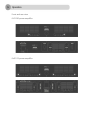
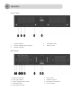
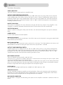
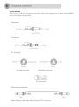
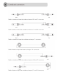
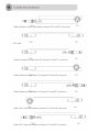
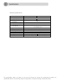
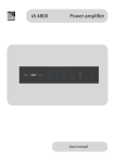
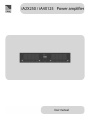
IMPORTANT SAFETY INSTRUCTIONS When using this electronic device, basic precautions should always be taken, including the following: 1. Read all instructions before using the product. 2. Do not use this product near water (e.g., near a bathtub, washbowl, kitchen sink, in a wet basement or near a swimming pool etc). 3. Use this device when you are sure that amplifier has a stable base and it is fixed securely. 4. This product, in combination with loudspeakers may be capable of producing sound levels that could cause permanent hearing loss. Do not operate for a long period of time at a high volume level or at a level that is uncomfortable. If you experience any hearing loss or ringing in the ears, you should consult with otorhinolaryngologists. The product should be positioned so that proper ventilation is maintained. 5. The product should be located away from heat sources such as radiators, heat vents, or other devices that produce heat. 6. The product should be connected to a power supply that is described in the operating instructions or are marked on the product. For continued protection against risk of fire, replace only with a fuse of the same type and having the same electrical rating. 7. The power supply cord should be undamaged and never share an outlet or extension cord with other devices so that the outlet or extension cord's power rating is exceeded. Never leave device plugged into the outlet when it is not being used for a long period of time. 8. Care should be taken that objects do not fall into liquids and liquids would not be spilled through, the enclosure's openings. 9. The product should be serviced by qualified service personnel if: The power supply cord or the plug has been damaged. Objects have fallen into or liquid has been spilled on the product. The product has been exposed to rain. The product has been dropped or the enclosure damaged. 10. There are some areas with high voltage inside, to reduce the risk of electric shock do not remove cover of the amplifier. The cover should be removed by the qualified personnel only. No user serviceable parts inside. CONTENTS: Before you start Introductions Features 4 4 Operation Front and rear view Front panel Rear panel Function description 5 6 6 7 Controls and connectors Connectors 8 Specifications General specifications 11 Introduction iA a group of amplifiers for professional contractor market. 100 V amplifiers with different channel number and output power configuration. Fan powered cooling system, rack mount. Amplifiers are designed to work under hard conditions and required minimum maintenance after installation. Used in a medium and large public address or voice evacuation systems. Features Without output transformer Switching power supply Dual or Single input mode Easy output voltage configuration 4Ω , 70V , 100V Low and High cut filter Front and rear view iA2X250 power amplifier iA4X125 power amplifier Front Panel 1. 2. 3. Signal indicator Output configuration indicator Protect indicator 4. 5. Ventilation holes Power switch Rear Panel 1. 2. 3. 4. 5. Balanced XLR input Input gain control Output configuration switch Ventilation holes Input mode selector 6. 7. 8. 9. Filter switch Amplifiers output Main power connector AC fuse holder Functions description SIGNAL INDICATOR Signal LED indicates audio signal in the amplifiers input. OUTPUT CONFIGURATION INDICATOR Amplifier output can be configured for 4Ω, 70V and 100V audio system by using switch in the rear panel. Output configuration LED indicates what kind of sound system is selected. Configuration depends on the connected speaker type. Output configuration switch must be set to position “4Ω” when low impedance loudspeaker (8Ω or 4Ω) is connected, position “70V” or “100V” suitable for loudspeaker with impedance matching transformer inside. PROTECT INDICATOR After power on protection LED starts illuminate and goes off after few seconds if the amplifier is not damaged. It is normal if protection indicator illuminates and then slowly fades after amplifier off. VENTILATION HOLES Cool air is pulled in through the front panel fan filters and eliminated through the rear panel ventilation holes. POWER SWITCH Use this switch to power on or off amplifier. BALANCED XLR INPUT This is balanced XRL line level audio input. Gain of this input can be adjusted by using gain control knob located above input connectors. INPUT GAIN CONTROL This control allows you to precisely adjust audio level in the input. Turn knob clockwise to increase and counterclockwise to decrease input gain. Input level can be adjusted from -∞ to 0 dB. OUTPUT CONFIGURATION SWITCH Amplifier output can be configured for 4Ω, 70V and 100V audio system by using output configuration switch. Configuration depends on the connected speaker type. Output configuration switch must be set to position “4Ω” when low impedance loudspeaker (8Ω or 4Ω) is connected, position “70V” or “100V” suitable for loudspeaker with impedance matching transformer inside. INPUT MODE SELECTOR There are available two input modes, single and dual. Dual mode: This is general used mode; each input is directed to this own output. All inputs require audio signal and all amplifier outputs work independently. Single mode: This mode allows two channels operate in parallel with same signal. In this mode two channel inputs are internally connected. Only one input require audio signal in order to active two amplifiers outputs. Do not use single mode then feeding the amplifier with two separate signals. FILTER SWITCH Filter reduce low and high audio frequency at 200 Hz and 10 kHz points by -3dB. AMPLIFIERS OUTPUT Use this connector to connect amplifier to the loudspeakers. Please take attention to the loudspeakers impedance and select corresponding output configuration by using output configuration switch. Please note: incorrect output configuration can damage loudspeaker or amplifier! MAIN POWER CONNECTOR This connector is designed for connecting main power to the amplifier. Connector is combined with fuse holder. AC FUSE HOLDER Please use 6.3A, 250V fuse. Disconnect main power cable before replacing fuse! Contact with qualified service if fuse blows up constantly. Connectors TS connector TRS connector XLR male connector XLR female connector RCA connector Cable wiring examples Cable to balanced input from balanced output. TRS connectors. Cable to unbalanced input from balanced output. TRS and TS connectors. Cable to balanced input from unbalanced output. TS and TRS connectors. Cable to unbalanced input from unbalanced output. TS connectors. Cable to balanced input from balanced output. XLR connectors. Cable to unbalanced input from balanced output. XLR and TS connectors. Cable to balanced input from unbalanced output. TS and XLR connectors. Cable to balanced input from balanced output. TRS and XLR connectors. RCA cable. Cable to unbalanced input from RCA output. RCA and TS connectors. Cable to balanced input from RCA output. RCA and XLR connectors. Cable to balanced input from RCA output. RCA and TRS connectors. Cable to RCA input from balanced output. RCA and XLR connectors. Cable to RCA input from balanced output. RCA and TRS connectors. General specifications iA2X250 Power supply Output power Total harmonic distortions Input sensitivity Max input level Gain control S/N ratio Frequency response Cooling Indicators Output Weight Dimensions iA4 X125 AC 220 V / 50 Hz 2 x 250 W 4 x 125 W < 0,1 % 0 dBu +20 dBu Min position -∞ Max position 0 dB 95 dB 20 Hz – 20 kHz Fan powered cooling system Signal, protection, output configuration 100 V, 70 V, 4 Ω 7,4 kg 9,7 kg 432 mm (W) x 88 mm (H) x 425 mm (D) The specifications above are correct at the time of printing this manual. For improvement purposes, all specifications for this unit, including design and appearance, are subject to change without prior notice AMC is a registered trademark of AMC Baltic www.amcpro.eu