1
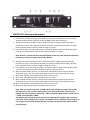
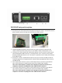
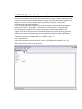
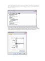
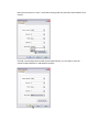
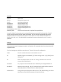
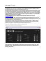
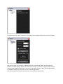
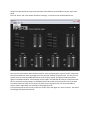
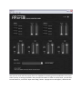
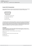
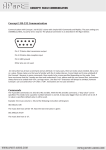
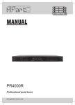
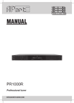
 PM1122‐INT DIGITAL INTERFACE REMOTE PM1122‐INT front panel description: 1. Clear wireless remotes knob: push this button for more than 2 seconds to clear the list of all assigned wireless remote settings stored in the PM1122‐INT internal memory. 2. Wireless remote learn button for zone 1: push this button to assign a wireless ‘Easywave’ remote by to zone 1. After pushing the button, the learn led 3 will flash for about 5 seconds, press any button on the wireless remote to assign it to zone 1. 3. Learn led for zone 1, after pushing button 2, this led will flash for about 5 seconds, during this time you can push a button on the wireless remote to assign it to zone 1. Note: buttons 1, 2 and 4 have been mounted slightly recessed to avoid unintended operation. If necessary, use a pen or pencil to push these buttons. 4. Wireless remote learn button for zone 2: push this button to assign a wireless ‘Easywave’ remote by to zone 2. After pushing the button, the learn led 5 will flash for about 5 seconds, press any button on the wireless remote to assign it to zone 2. 5. Learn led for zone 2, after pushing button 4, this led will flash for about 5 seconds, during this time you can push a button on the wireless remote to assign it to zone 2. 6. Music selector indicator for zone 1, these leds will indicate which music source has been selected for zone 1. You can use the white fields next to the leds to write the source type. 7. Music level indicator: these leds show the music level for zone 1. 8. Micro level: these leds show the microphone level for zone 1. 9. Music selector indicator for zone 2, these leds will indicate which music source has been selected for zone 2. You can use the white fields next to the leds to write the source type. 10. Music level indicator: these leds show the music level for zone 2. 11. Micro level: these leds show the microphone level for zone 2. Note: when you power on the unit, “LEARN” leds 3 and 5 will light up during a few seconds. Also while they are lit, the micro level led bar 11 will show the baudrate as stored in the PM1122‐INT internal memory. Bottom led = 2400, second led = 4800, third led = 9600, top led = 19200. Factory default is 19200. The PM1122‐INT will only operate if connected to a PM1122 pre‐amplifier using a standard CAT5 cable. Power supply for the interface is provided by the pre‐amplifier’s power supply. Do not attempt to connect the PM1122‐INT CAT5 connectors to anything other than a PM1122 CAT5 connector. PM1122‐INT back panel description: 1. RF antenna: this is the antenna from the optional ‘Easywave’ receiver. To install the receiver, please carefully remove the top cover and slide the module in place. 2.
3.
4.
5.
6.
COM A and COM B connectors: these contacts are used to connect an optional wired remote. COM A is used to select presets 1 to 6. COM B is used to select presets 7 to 12. Contacts 1 to 6: these contacts are used to select preset 1 to 6 by means of a rotary switch connected between COM A and 1 to 6. To select presets 7 to 12, connect a rotary switch between COM B and contacts 1 to 6. This means it is possible to use 2 wired preset selectors on the PM1122‐INT. RS‐232 port: connect a suitable RS‐232 cable on this port to connect the PM1122‐INT to a Terminal program such as Hyperterminal or another third party application able to control the PM1122‐INT. Zone 1 CAT5 cable connector: connect a CAT5 cable from this connector to the PM1122 zone 1 CAT5 connector to enable remote control of the PM1122 pre‐amplifier. This is not a LAN connection, so please never attempt to connect this connector to a computer or network or anything other than a PM1122 CAT5 connector ! Zone 2 CAT5 cable connector: connect a CAT5 cable from this connector to the PM1122 zone 2 CAT5 connector to enable remote control of the PM1122 pre‐amplifier. This is not a LAN connection, so please never attempt to connect this connector to a computer or network or anything other than a PM1122 CAT5 connector ! PM1122‐INT Digital Interface Remote serial communication setup. In order to communicate with the PM1122 remote interface using a personal computer, you will have to set up your communication parameters correctly. You also need sufficient rights on your computer, so ask your system administrator for assistance if necessary. Serial cable specifications are also mentioned below. On a PC running on Windows 2000/XP, you will find a suitable communication program called Hyperterminal (Start ‐> All programs ‐> Accessories ‐> Communications ‐> Hyperterminal). Open the program. If a popup screen comes up asking you to make it your default telnet program, click cancel. Next you may be asked what telephone line you will be using, ignore this and select your PC serial communication port as standard, usually this is COM 1. Please take a look at the screenshots below for clarification. For those who are familiar with Hyperterminal, default com settings on the PM1122‐INT are “19200 : 8 : none : 1” Open “Hyperterminal”. Make a new connection and call it PM1122. Under the pull‐down menu labeled “File”, click “New Connection” to create a new connection. Enter a name for the new connection, e.g. “PM1122” and click “OK”. As mentioned before, select your computer’s serial communication port. Under the pull‐down menu labeled “Connect Using” select your RS232 Com port, usually this is COM1. To check the COM port name, look in Control Panel ‐> System ‐> Hardware ‐> Device Manager, you may need Administrator rights to access these pages, so ask your system administrator for assistance if necessary. Set the baudrate to 19200. You find this setting under the pull‐down menu labeled “Bits per second”. 19200 is the standard PM1122 interface baudrate, after connecting, you can change it to 2400, 4800, 9600 or 19200 using the commands as mentioned in the instruction set. Next set Flow control to “none”. You find this setting under the pull‐down menu labeled “Flow control”. Click OK, normally Hyperterminal will connect automatically, you are ready to start the communication between PC and PM1122 interface. Click on the telephone symbol to connect or disconnect to the PM1122‐INT. The bottom taskbar shows the connection status (connected / disconnected and the applied baudrate, databits, parity and stopbits). RS232 Cable Specifications. RS232 connection on the PM1122 interface: A straight through PC Serial Cable is used to communicate from the RS232 port to a third‐party controller such as a PC using Hyperterminal to the RS232 serial port on the PM1122INT unit. This kind of cables can be sourced locally, every computer shop should be able to supply you the right cable type. Pin 2: TX data: data transmission output Pin 3: RX data: data reception input Pin 5: GND: ground All other pins are not used. Instruction set PM1122‐INT The PM1122‐INT can be controlled using RS‐232. Initial port settings are 19200 bits per second, 8 data bits, no parity, 1 stop bit and no flow control. The baud rate can be configured at different values, but this will be described later. For details on the serial cable and Terminal connection settings, refer to the PM1122‐INT interface serial communication setup document. Standard ASCII strings are used to control the PM1122‐INT so it’s possible to use Terminal software (e.g. HyperTerminal) to test, configure and/or control it. Instructions are not case sensitive. Each string must be ended with a Carriage Return (ASCII code 13 or \n) An instruction consists of a command, an attribute and possible one ore more parameters. E.g. the instruction to switch the music volume from zone 1 at maximum will look like this: SET MSCLVL ZONE1 100\n where SET is the instruction, MSCLVL the attribute, ZONE1 the first parameter and 100 the second parameter. Commands This is a list of commands with a brief description SET Set the value of a variable GET Get the value of a variable RCL Recall a Preset LRN Learn a code of Easywave RF switch CLR Clear preset or Easywave RF codes HELP Lists Commands and Attributes LST Lists Commands and Attributes (same as HELP) STR Store a Preset INC Increase the value of a variable DEC Decrease the value of a variable Attributes The attributes can be grouped in controls and settings. Controls will really “control” the PM1122 while settings only determine the behaviour of the PM1122‐INT. Controls: MSCLVL: Music Level MICLVL: Microphone Master Level SELECT: Input Source Selection MINMSCLVL: Minimum Music Level MAXMSCLVL: Maximum Music Level MINMICLVL: Minimum Microphone Level MAXMICLVL: Maximum Microphone Level To be complete, there is also a RESERVED_REG: which has no function but is kept for future possibilities Except for “SELECT”, all controls can be used with following commands: SET, GET, INC, DEC. “SELECT” can only be used with SET and GET. After the attribute, the zone needs to be specified, this can be ZONE1 or ZONE2. SET commands must contain a value which is a number between 0 and 100. For SELECT this is A, B, C or D. The INC and DEC command will increase or decrease by one if no value is specified. Settings: Unless otherwise stated, settings can only be used with the SET command and will only have ON or OFF as possible value. The first 3 settings are available to ease the use of Terminal software for configuration. ECHO: Echo of received characters can be switched on or off. CR: Replied strings are terminated by “\n” when setting is off or “\n\r” (CR+LF) when setting is on. BS: When on, backspace echo will clear the “wrong” character in the Terminal window ( <BS><SPACE><BS>). RESPONSE: Any response of the PM1122‐INT can be disabled by switching RESPONSE off. BAUDRATE: Baud rate can be changed. Only SET command can be used. Possible values are 2400, 4800, 9600 or 19200. 19200 is the default baudrate. DOUBLECLICK: Setting of the optional Easywave radio receiver, if ON, doubleclicking the volume down knob on the RFKEY transmitter will mute the volume. RFKEY: PRESET: ROTARYATSTART: VALFB: INFO: Setting of the Easywave radio receiver only. Presets can be stored, recalled and cleared. Commands are STR, RCL and CLR. With store and recall, first optional parameter is ZONE1 or ZONE2 and then the preset number between 1 and 64. With the CLR command, the only parameter is the preset number that needs to be cleared or “ALL”. When this is ON, the PM1122‐INT will load the preset selected by the wired rotary switch at startup (power on). If this setting is on, the PM1122‐INT will send a string whenever a control is changed containing the control name and its value. Can only be used with GET and is only functional when VALFB is on. It will respond with a list of all controls and corresponding values. Next attributes are constants, which can only be used with GET SERIAL: Returns the Serial Number (if supported) HWVRSN: Returns the Hardware Version Number (if supported) SWVRSN: Returns the Software Version Number Easywave An optional Easywave receiver module can be mounted inside the PM1122‐INT. An eight button RF switch can be assigned to a zone of the PM1122. 4 buttons named A to D are used for selecting the source or to recall a preset. By default, these buttons are used to select source A to D. Next to that are an up and down button controlling the music level and finally the same 2 buttons controlling the microphone level. Assigning an RF switch is as simple as pushing the “Learn” button from the corresponding zone (x) and than pushing any button of the RF switch within 5 seconds. In case the PM1122‐INT is in a less accessible place, this can also be done by an RS232 instruction. “LRN RFKEY ZONEx\n” has the same effect as pushing the “Learn” button from zone x. Clearing the memory or un‐assigning the RF switches also can be done in 2 ways: pushing the “Clear” button on the PM1122‐INT for at least 2 seconds or by the instruction “CLR RFKEY ALL”. Assigning the first 4 buttons (A to D) from zone x to a preset can only be done by the following instruction: SET RFKEY ZONEx PRESET\n The presets that are recalled are 1 to 4 if the switch is assigned to zone 1 or 7 to 10 if the switch is assigned to zone 2. To put it back to select the sources, next instruction needs to be executed: SET RFKEY ZONEx SELECT\n There’s also a feature that both music as mic level can be put at minimum by double clicking the volume down button. This feature is enabled by “SET DOUBLECLICK ON\n” or disabled by “SET DOUBLECLICK OFF\n”. Presets A preset is a set of stored values. These values are Music Level, Mic Level and Source Selection for zone 1 and/or zone 2. A preset can be stored, recalled or cleared. The only way to store a preset is by using the RS232 interface. A preset can be recalled using the same interface, using the contacts at the back side of the PM1122 or with an Easywave RF switch, if buttons A to D are assigned as preset selector knobs instead of source selectors, as described earlier. Preset 0 can only be recalled (can not be overwritten) and this will set all levels at the minimum and source selections at source A. It can only be recalled by the serial interface. Storing a preset will copy the current settings to the internal memory of the PM1122‐INT. It is possible to save only the settings of one specific zone. A few examples: • “STR PRESET 2\n” will store all settings to preset number 2 for zone 1 AND zone 2. • “STR PRESET ZONE1 3\n” will store the settings of zone 1 to preset 3. When preset 3 will be recalled, only zone1 will change. A preset can be overwritten by storing at the same preset number or cleared by the CLR command. Recalling a preset will change the values to those of the corresponding memory location. Again a few examples: • “RCL PRESET 2\n” will recall the settings as stored in preset 2 (e.g. if the preset is valid for both zones, then the stored settings will be applied to BOTH zones). • “RCL PRESET ZONE2 0\n” will put the levels of zone 2 to the minimum and source of zone 2 to “A”. • “RCL PRESET ZONE1 1\n” will apply the preset number 1 settings to zone 1 only, even if the preset has been stored as a zone 1 and 2 preset. Presets can also be selected by connecting wired remotes using the contacts COM A an B and the contacts labeled 1 to 6. They are present at the back on euroblock connectors. A first preset selector wired to COM A and to contacts 1 to 6 will enable you to recall presets numbered 1 to 6, where COM A is the common wire on the selector and contacts 1 to 6 are the contacts operated by the rotary selector. A second preset selector wired to COM B and to contacts 1 to 6 will enable you to recall presets numbered 7 to 12. Please note that you can specify whether or not the presets selected by the wired selectors are being selected at power up with the “SET ROTARYATSTART ON” or “SET ROTARYATSTART OFF” setting. PM1122 Control Panel In order to show you some of the RS‐232 remote control capabilities of PM1122 and PM1122‐INT, we have developped a custom application called PM1122 Control Panel. You will need a PC with a RS‐232 9 pin connector running on Windows 2000/XP and a standard straight through serial cable. Cable details can be found in the PM1122‐INT manual. If no serial port is available on your PC, you can also use a USB to serial converter, however, we can not guarantee the functionality of this kind of devices. If necessary, first install the USB to serial converter drivers (if necessary) before installing the PM1122 Control Panel software. To download the latest version of the control panel application, please visit our website: www.apart‐audio.com After downloading, start the installation program and follow the instructions as shown on the screen. You will need sufficient user rights on your PC in order to install and run the program, so please ask your system administrator for assistance if necessary. After a successfull software install, connect the PM1122 and the PM1122‐INT to your PC using the appropriate cables and start the application. If you have not assigned a shortcut to the application, doubleclick the PM1122.exe file found in the standard installation directory: C:\Program Files\Audioprof\PM1122 Control Panel\PM1122.exe The first screen you will see should look like this: Before attempting to make adjustments to the settings, check the connection settings. In the upper taskbar, click “Tools”. A drop‐down selection menu will appear, select options, a popup screen will appear, it looks like this: In the left menu tree, select “Connection”, the right part of the popup will show the connection details: Here you can select your computer’s COM port used for serial communication, and also select the baudrate, standard setting is 19200. If the “Connect on startup” is selected, the program will attempt to connect to the PM1122‐INT whenever you run it. If you make a change to one of the settings and wish to change the settings for future use, click the “Save Settings” button. Next you can select the “Labels” in the left menu tree, the screen looks like this: Here you can change the names of the four line sources connected to your PM1122 for easy identification. E.g. click in the SourceA field and type a new name for this source, such as tuner or CD player. Click on the “Save” button to save the names you assigned to the different sources. Now you can test the connection and functionality of the program. Go back to the main screen shown above. The power led indicator in the right top corner program will show the on/off status of the PM1122 pre‐amplifier. Switch on the PM1122 and the power indicator in the program will also light up. In the main screen you can perform a few basic adjustments: select source A to D for zone 1 and 2 and adjust the music and microphone levels using the mouse and the level sliders. The PM1122 will immediately adjust these settings, so connect a music source and amplifier + speaker to hear the results. The labels next to the Source A to D buttons will also show the names you assigned in the “Labels” option menu. In this initial screen you can perform a few basic adjustments: select source A to D for zone 1 and 2 and adjust the music and microphone levels using the mouse and the level sliders. The PM1122 will immediately adjust these settings, so connect a music source and amplifier + speaker to hear the results. The main screen will be called “mixer screen” on the next pages. If you want to program a certain preset for zone 1 and/or zone 2, you will have to make the level and source select adjustments in the mixer screen in order to save them. This will be described later. We will now proceed to the next screen and show a few features not available on the pre‐amp’s front panel. Click the “Zones” tab in the top bar and select “Settings”. The mixer screen should look like this: Here you can set minimum and maximum levels for music and microphone in zone 1 and 2. Please note that the top sliders will move according to the min and max settings you specify here. This way you can prevent users to exceed a predefined level for music and mic signals, providing excellent protection against overloads and abuse. These settings can be saved in the PM1122‐INT memory. Please note that the mic and music level led meters on the PM1122‐INT front panel will not reach full scale if you have set a level lower than 100% in this screen, the same for the minimum level, you will not be able to entirely mute a signal when you specified a value larger than 0%. Time to proceed to the next screen, under the “Zones” tab in the upper bar, select “Presets”, the screen will enlarge and should look like this: Here you can recall and save presets.There is a dropdown list showing presets numbered 1 to 12. If you select a preset, all settings specified in the preset will be loaded. In order to recall presets, you will have to save them first, so click the “Open Save dialog” button. A popup screen will appear, it looks like this: Here you can specify if the settings you make in the mixer and source select screen will be valid for zone 1 and/or zone 2. Simply set the levels and select the source in the mixer screen, click on one of the zone buttons under “What would you like to save” and give the preset a name if you wish. Next click the “Save preset” button. The settings you made will be stored in the PM1122‐INT internal memory and can be recalled using the Control panel software, or by using the wired preset selectors connected to the euroblock connectors at the back of the PM1122‐INT. The wiring details are described in the PM1122‐
INT manual. Finally you can specify whether or not the buttons named A to D on the optional RFKEY wireless transmitters will be used to select source A to D or preset 1 to 4 (transmitter zone 1) or presets numbered 7 to 10 (transmitter zone 2). To enable preset selection, mark the white fields above the wireless transmitters to enable preset selection. These settings are also stored in the PM1122‐INT internal memory.