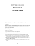
1
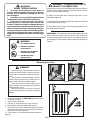
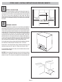
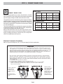
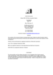
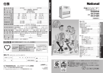
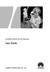
42U
Freestanding Electric Range
Installation Instructions
for Models: HES232U, HES236UHES246U, HES247U, HES245U,
HES242U, HES256U, HES255U, HES252U
PLEASE READ ENTIRE INSTRUCTIONS BEFORE PROCEEDING.
Save these instructions for the local electrical
inspector’s use.
INSTALLER:
Please leave these Installation Instructions with this
unit for the owner.
OWNER:
Please retain these instructions for future reference.
IMPORTANT:
Household Appliances
IMPORTANT SAFETY INSTRUCTIONS
Please read all instructions before using this appliance.
Table of Contents
Safety Instructions and Applicable Codes ........................................................................... 1, 2
Ventilation and Cabinet Preparation ....................................................................................... 3
Range Cord Connection .................................................................................................... 4, 5
Anti-Tip Bracket Installation .................................................................................................. 6
Final Install ......................................................................................................................... 6
• Remove all tape and packaging before using the range.
Destroy the carton and plastic bags after unpacking the range.
Never allow children to play with packaging material.
PARTS PROVIDED
Anti-Tip Bracket
• Proper Installation - Be sure your appliance is properly
installed and grounded by a qualified technician in accordance
with the National Electrical Code ANSI/NFPA No. 7 latest edition
and local electrical code requirements.
Important: Local codes vary. Installation, electrical connections
and grounding must comply with all applicable codes.
PARTS NEEDED:
Power Supply Cord Kit (50 Amps)
Standard Measuring Tape
Phillips head Screwdriver
1-1/4” Wrench
Pencil
Install only per installation instructions provided in the literature
package for this range.
Ask your dealer to recommend a qualified technician and an
authorized repair service. Know how to disconnect the power to
the range at the circuit breaker or fuse box in case of an emergency.
WARNING
Before installing, turn power OFF at
the service panel. Lock service panel
to prevent power from being turned
ON accidentally.
• User servicing - Do not repair or replace any part of the
appliance unless specifically recommended in the manuals. All
other servicing should be done by a qualified technician. This may
reduce the risk of personal injury and damage to the range.
CAUTION
Unit is heavy and requires at least two
persons or proper equipment to
move.
• Never modify or alter the construction of a range by removing
leveling legs, panels, wire covers, anti-tip brackets/screws, or
any other part of the product.
• Notice: DO NOT LIFT RANGE BY DOOR HANDLE. Remove
the door for easier handling and installation. See Section ‘Removing
Oven Door’ on next page.
WARNING
IF THE INFORMATION IN THIS
MANUAL IS NOT FOLLOWED EXACTLY,
A FIRE OR EXPLOSION MAY RESULT
CAUSING PROPERTY DAMAGE,
PERSONAL INJURY OR DEATH.
WARNING
Stepping, leaning or sitting on the doors or drawers of this range
can result in serious injuries and also cause damage to the range.
Do not allow children to climb or play around the range. The
weight of a child on an open door may cause the range to tip,
resulting in serious burns or other injury.
CAUTION
Do not use the oven or warmer drawer (if equipped) for storage.
WARNING
IMPORTANT:
LOCAL CODES VARY. INSTALLATION, ELECTRICAL
CONNECTIONS AND GROUNDING MUST COMPLY WITH ALL
APPLICABLE CODES.
Do not store items of interest to children in the cabinets above the
range or on the backguard of a range. Children climbing on the
range to reach items could be seriously injured.
Page 1
WARNING
RANGE TIPPING HAZARD
•
All ranges can tip and injury could result. To
prevent accidental tipping of the range, attach it to
the wall, floor or cabinet by installing the Anti-Tip
Device supplied.
•
A risk of tip-over may exist if the appliance is not
installed in accordance with these instructions.
•
If the range is pulled away from the wall for
cleaning, service, or any other reason, ensure that
the Anti-Tip Device is properly reengaged when the
range is pushed back against the wall. In the event of
abnormal usage (such as a person standing, sitting, or
leaning on an open door), failure to take this precaution
could result in tipping of the range. Personal injury
might result from spilled hot liquids or from the range
itself.
WARNING
WARNING - TO REDUCE THE RISK OF
A RANGE TOP GREASE FIRE:
a) Never leave surface units unattended at high settings. Boilovers
cause smoking and greasy spillovers that may ignite. Heat oils
slowly on low or medium settings.
b) Always turn hood ON when cooking at high heat or when
cooking flaming foods.
c) Clean ventilating fans frequently. Grease should not be allowed
to accumulate on fan or filter.
d) Use proper pan size. Always use cookware appropriate for the
size of the surface element.
IMPORTANT - Do not attempt to operate the range during power
failure. If the power fails, always turn off the range. If the range
is not turned off and the power resumes, the range will begin to
operate again. Once the power resumes, reset the clock and oven
function.
• ALL RANGES CAN TIP
• INJURY TO PERSONS
COULD RESULT
• INSTALL ANTI-TIP DEVICE
PACKED WITH RANGE
• SEE INSTALLATION
INSTRUCTIONS
Removing the Door
WARNING
• Make sure oven is cool and power to the oven
has been turned off before removing the door.
Failure to do so could result in electrical shock or
burns.
• The oven door is heavy and fragile. Use both
hands to remove the oven door. The door front is
glass. Handle carefully to avoid breakage.
• Grasp only the sides of the oven door. Do not
grasp the handle as it may swing in your hand and
cause damage or injury.
• Failure to grasp the oven door firmly and
properly could result in personal injury or product
damage.
Figure A
1. Be sure to read the above WARNING before attempting
to remove oven door.
2. Open the door completely.
3. Flip lever on hinge toward you. (see Figure A).
4. Close the door to approximately halfway open.
5. Holding the door firmly on both sides using both hands,
pull the door straight out of the hinge slots. Hold firmly,
the dooris heavy (See Figure B).
6. Place the door in a convenient and stable location for
cleaning.
Page 2
Figure B
STEPS 1 AND 2: INSTALL VENTILATION AND PREPARE CABINETS
1
INSTALL VENTILATION
It is strongly recommended to install a hood above this range. For
most kitchens with a wall mounted hood, a certified hood rating
of not less than 350 CFM is recommended. Bosch hoods rated at
350 CFM or more when operated on High meet the above
requirement and are recommended for this purpose. The range
hood must be installed according to instructions furnished with
the hood.
2
30” Minimum Centered
30” Min.
No Clearance to Wall
Required
No Clearance to Wall
Required
PREPARE CABINETS
This unit is designed for installation in a countertop near adjacent
walls and projecting surfaces constructed of combustible materials.
There must be a minimum clearance of 30 inches between the top
of the cooking surface and the bottom of an unprotected wood or
metal cabinet; or 24 inches when bottom of wood or metal cabinet
is protected by not less than 1/4" of flame retardant material
covered with not less than No. 28 MSG sheet metal, 0.015 inch
stainless steel’ or 0.024 inch aluminum or copper. (See Figure I).
The minimum horizontal distance(s) from the side and back edge
of the unit to adjacent vertical combustible walls are as follows:
Zero clearance is permitted on rear, right and left walls.
For the cabinets over the cooking surface and the adjacent cabinets,
the maximum cabinet depth from back wall is 13 inches.
Figure 1
Instructions were determined using Standard American base
cabinets measuring 36" high x 24" deep (see Figures 2 & 3).
22"
3"
If nonstandard cabinets are used, care should be taken to alter
dimensions accordingly.
NOTICE: Some cabinet finishes cannot survive the temperatures
allowed by U.L., particularly self-cleaning ovens; the cabinets may
discolor or stain. This is most noticeable with laminated cabinets.
8"
Figure 2
30” Min.
between
cabinets
Figure 3
Page 3
STEP 3: CONNECT RANGE CORD
3
MODEL HES23
CONNECT RANGE CORD
Ranges are dual rated for use on either 120/240 VAC or 120/208
VAC. See table for power ratings and circuit breaker sizes based
upon the supply voltage for each mode (See chart at left).
This appliance may be connected to the power supply by installing
flexible conduit or a power cord set. The electrical rating of the
power cord set (not supplied) must be 120/240 volt, 50 amperes
minimum for models HES. The power cord set shall be marked
“For Use with Ranges.”
The power supply shall be connected to the range terminal block
compartment located in the lower left rear corner, accessible by
removing the storage drawer below the oven.
Remove the terminal box cover by removing the cover screw.
Install the proper connector in knockout(s) provided. The electrical
supply, including connectors or power cord, can lie anywhere
within the shaded area (See Figure 2.)
VOLTS
A.C.
HZ
RATING
KW
CIRCUIT
BREAKER
120/240
60
12.1
50 AMPS
120/208
60
9.1
45 AMPS
MODEL HES24, HES25
VOLTS
A.C.
HZ
RATING
KW
120/240
60
12.6
50 AMPS
120/208
60
9.5
50 AMPS
Electrical Connection Procedures
Refer to Figure 4 and Figures A, B, C, D & E (next page) for further explanation.
WARNING
CONSULT YOUR INSTRUCTIONS FOR ‘ELECTRICAL CONNECTION PROCEDURES’. COPPER WIRE MUST BE USED
FOR CONNECTION TO THE TERMINAL BLOCK. WHEN POWER SUPPLY CORD KIT IS USED TO CONNECT RANGE TO
THE POWER SUPPLY. USE ONLY CORD KITS RATED 125/240 VOLTS MINIMUM AND MARKED FOR USE WITH RANGES.
REFER TO INSTALLATION INSTRUCTIONS FOR PROPER CORD KIT AMPERAGE RATING, RISK OF FIRE OR
ELECTRICAL SHOCK MAY BE INCURRED IF AN INCORRECT SIZE RANGE CORD KIT IS USED, THE INSTALLATION
INSTRUCTIONS ARE NOT FOLLOWED, OR THE STRAIN RELIEF BRACKET IS DISCARDED.
RISK OF ELECTRIC SHOCK FRAME GROUNDED TO NEUTRAL OF APPLICANCE THROUGH A LINK GROUNDING
THROUGH THE NEUTRAL CONDUCTOR IS PROHIBITED FOR NEW BRANCH-CIRCUIT INSTALLATIONS. (1996 NEC)
MOBILE HOMES AND RECREATIONAL VEHICLES, OR IN AN AREA WHERE LOCAL CODES PROHIBIT GROUNDING
THROUGH NEUTRAL CONDUCTOR. FOR INSTALLATIONS WHERE GROUNDING THROUGH THE NEUTRAL CONDUCTOR IS PROHIBITED:
(1) DISCONNECT THE LINK FROM THE NEUTRAL.
(2) USE GROUNDING TERMINAL OR LEAD TO GROUND UNIT: AND
(3) CONNECT NEUTRAL TERMINAL OR LEAD TO BRANCH CIRCUIT NEUTRAL IN USUAL MANNER
(WHEN THE APPLIANCE IS CONNECTED BY MEANS OF A CORD KIT, USE 4 CONDUCTOR
CORD FOR THIS PURPOSE).
Remove ground
strap from terminal
block. Install with
care, the green
ground wire as
shown at left. Attach
ground wire and
strap with screw
provided with strap.
Center or white wire
must always be
attached to the
central terminal on
block.
All screw and nut
connections must be
tight.
Figure 4
Page 4
CIRCUIT
BREAKER
Power Supply Connections
Three Wire Connection
The Four Wire Connection is preferred, but where
local codes and ordinances permit grounding through
neutral and/or conversion to four wire is impractical, unit
may be connected to the power supply via a three wire
connection.
1. Disconnect electrical power at breaker box.
2. Remove the terminal block cover to expose the
junction box (See Figure A).
3. Remove top nut, star washer, and round washer from
each post.
Note: DO NOT remove last round washer, last nut or
internal wiring leads.
4. Attach white wire, round washer, star washer and nut
IN THIS ORDER on top of ground strap on center post.
5. Attach red wire, round washer, star washer and nut IN
THIS ORDER to left post.
6. Attach black wire, round washer, star washer and nut
IN THIS ORDER to right post (See Figure B).
7. Tighten all connections securely and replace terminal
block cover (See Figure C).
Figure A
Figure B
Four Wire Connection (Preferred Method)
1. Disconnect electrical power at breaker box.
2. Remove the terminal block cover to expose the
junction box (See Figure A).
3. Remove top nut, star washer, and round washer from
each post.
Note: DO NOT remove last round washer, last nut or
internal wiring leads.
4. Remove screw from bottom end of ground strap.
5. Remove ground strap from center post, rotate so that
wide end is at top and attach wide end to range
through hole below junction box. Attach green wire on
top of ground strap. Tighten Screw (See Figure D).
6. Attach red wire, round washer, star washer and nut IN
THIS ORDER to left post.
7. Attach white wire, round washer, star washer and nut
IN THIS ORDER to center post.
8. Attach black wire, round washer, star washer and nut
IN THIS ORDER to right post (See Figure E).
9. Tighten all connections securely and replace terminal
block cover.
Figure C
Figure D
Figure D
Note: DO NOT plug in range at this
time. Proceed to steps 4 and 5.
Page 5
Figure E
STEPS 4 AND 5: INSTALL ANTI-TIP BRACKET AND FINAL INSTALL
Warming Drawer
1 9/16”
Flush
Wrench
Adjustable legs
Figure 6
4
Figure 7
Screw
Screw
INSTALL ANTI-TIP BRACKET:
1. Adjust height of range and level by rotating the adjustable
leg supports, (see Figure 6) using 1-1/4" wrench.
2. Measure to locate bracket position as shown in Figure 7.
3. Secure bracket with 2 screws.
Figure 8
5
FINAL INSTALL:
1. Move range close enough to the opening to plug into the
receptacle.
2. Slide range into position insuring that the left back leg slides
under the anti-tip bracket. Range will sit 3/4” away from back
wall when properly installed.
3. Carefully tip range forward to insure that the anti-tip bracket
engages the range back brace and prevents tip-over.
4. Turn on electrical power. Check range for proper operation as
described in Use and Care Manual.
Screw
Screw
Figure 9
Note: if LCD screen flashes and beeps, the wiring is incorrectly
installed. Immediately disconnect power at breaker and return to
step 3: CONNECT RANGE CORD.
WARNING
•
•
•
ALL RANGES CAN TIP.
INJURY TO PERSONS COULD
RESULT
INSTALL ANTI-TIP DEVICE
PACKAGED WITH RANGE.
CAUTION
DO NOT USE HAND TRUCK
OR APPLIANCE DOLLY ON
THE BACK OR FRONT OF
THIS UNIT. HANDLE FROM
SIDE ONLY!
SEE INSTALLATION INSTRUCTIONS
Page 6
WARNING
ELECTRICAL SHOCK
HAZARD - DISCONNECT
POWER BEFORE
SERVICING.
FAILURE TO DO SO CAN
RESULT IN DEATH OR
ELECTRICAL SHOCK.
BSH reserves the right to change specifications or design without notice. Some models are certified for use in Canada. BSH is not
responsible for products which are transported from the United States for use in Canada. Check with your local Canadian distributor
or dealer. BSH Home Appliances, Corporation, 5551 McFadden Avenue, Huntington Beach, CA 92649.
For the most up to date critical installation dimensions by fax, use your fax handset and call 702/833-3600. Use code #8030.
5551 McFadden Avenue, Huntington Beach, CA 92649 • 800/944-2904
5060003398 Rev. A • © BSH Home Appliances Corporation 2003 • Litho U. S. A. 6/03
Page 7