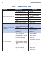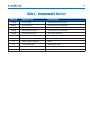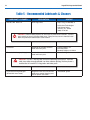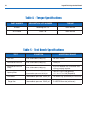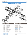
1
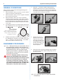
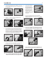
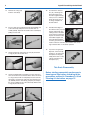
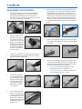
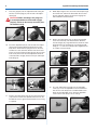
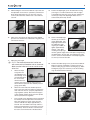
Authorized Technician TECHNICAL MAINTENANCE MANUAL LEGEND LX SECOND STAGE Copyright ©2000 Aqua Lung America, Inc. Rev. 7/2002 2 Legend LX Second Stage Service Manual Contents COPYRIGHT NOTICE...............................................................................................................................................3 INTRODUCTION .......................................................................................................................................................3 WARNINGS, CAUTIONS, & NOTES.........................................................................................................................3 SCHEDULED SERVICE............................................................................................................................................3 GENERAL GUIDELINES ..........................................................................................................................................3 GENERAL CONVENTIONS......................................................................................................................................4 DISASSEMBLY PROCEDURES...............................................................................................................................4 REASSEMBLY PROCEDURES................................................................................................................................7 FINAL TESTING......................................................................................................................................................10 Second Stage Opening Effort Test.................................................................................................................................................... 10 Second Stage Air Flow Test............................................................................................................................................................... 10 Second Stage Purge Flow Test ......................................................................................................................................................... 10 External Leak Test .............................................................................................................................................................................. 10 Subjective Breathing Test.................................................................................................................................................................. 10 TABLE 1 - FIRST-STAGE TROUBLSHOOTING GUIDE.........................................................................................12 TABLE 2 - RECOMMENDED TOOL LIST ..............................................................................................................13 TABLE 3 - RECOMMENDED LUBRICANTS AND CLEANERS...........................................................................14 PROCEDURE A - CLEANING AND LUBRICATION..............................................................................................15 TABLE 4 -TORQUE SPECIFICATIONS..................................................................................................................16 TABLE 5 - TEST BENCH SPECIFICATIONS .........................................................................................................16 LEGEND LX EXPLODED PARTS DRAWING ........................................................................................................17 3 COPYRIGHT NOTICE An Official Inspection consists of: This manual is copyrighted, all rights reserved. It may not, in whole or in part, be copied, photocopied, reproduced, translated, or reduced to any electronic medium or machine readable form without prior consent in writing from Aqua Lung America. It may not be distributed through the internet or computer bulletin board systems without prior consent in writing from Aqua Lung America. ©2002 Aqua Lung America, Inc. 1. A pressurized immersion test of the entire unit to check for air leakage. 2. Checking for stable intermediate pressure that is within the acceptable range. 3. Checking for opening effort that is within the acceptable range. 4. Checking for smooth operation of the control knob and venturi switch. 5. A visual inspection of the filter for debris or discoloration. 6. A visual inspection of the exhaust valve to see that it is in good shape and that it’s resting against a clean surface. 7. A visual inspection of the mouthpiece looking for tears or holes. 8. Pulling back hose protectors and checking that the hoses are secure in the hose crimps. Legend LX Second-Stage Service Manual INTRODUCTION This manual provides factory prescribed procedures for the correct service and repair of the Aqua Lung Legend LX second-stage regulator. It is not intended to be used as an instructional manual for untrained personnel. The procedures outlined within this manual are to be performed only by personnel who have received factory authorized training through an Aqua Lung Service & Repair Seminar. If you do not completely understand all of the procedures outlined in this manual, contact Aqua Lung to speak directly with a Technical Advisor before proceeding any further. If a regulator fails item #1,2,3 or 4 the entire regulator should be overhauled. If a regulator fails 4,5,6 or 7 it will be up to the technician’s discretion whether or not a full overhaul is required. WARNINGS, CAUTIONS, & NOTES GENERAL GUIDELINES Pay special attention to information provided in warnings, cautions, and notes that are accompanied by one of these symbols: 1. In order to correctly perform the procedures outlined in this manual, it is important to follow each step exactly in the order given. Read over the entire manual to become familiar with all procedures before attempting to disassemble the first-stage, and to learn which specialty tools and replacement parts will be required. Keep the manual open beside you for reference while performing each procedure. Do not rely on memory. 2. All service and repair should be carried out in a work area specifically set up and equipped for the task. Adequate lighting, cleanliness, and easy access to all required tools are essential for an efficient repair facility. 3. As the regulator is disassembled, reusable components should be segregated and not allowed to intermix with nonreusable parts or parts from other units. Delicate parts, including inlet fittings and crowns which contain critical sealing surfaces, must be protected and isolated from other parts to prevent damage during the cleaning procedure. Use only genuine Aqua Lung parts provided in the Legend first-stage overhaul parts kit (PN 900112). DO NOT attempt to substitute an Aqua Lung part with another manufacturer’s, regardless of any similarity in shape or size. Do not attempt to reuse mandatory replacement parts under any circumstances, regardless of the amount of use the product has received since it was manufactured or last serviced. When reassembling, it is important to follow every torque specification prescribed in this manual, using a calibrated torque wrench. Most parts are made of either marine brass or plastic, and can be permanently damaged by undue stress. WARNINGS indicate a procedure or situation that may result in serious injury or death if instructions are not followed correctly. CAUTIONS indicate any situation or technique that will result in potential damage to the product, or render the product unsafe if instructions are not followed correctly. are used to emphasize important points, F NOTES tips, and reminders. SCHEDULED SERVICE If the regulator is subjected to less than 50 dives per year, it is permissible to overhaul it every other year with an inspection procedure being performed on the “off” years. For example: Year #1: Inspection Year #2: Overhaul Year #3: Inspection Year #4: Overhaul and so on. Both Inspections and Overhauls need to be documented in the Annual Service & Inspection Record in the back of the Owner’s Manual to keep the Limited Lifetime Warranty in effect. If a regulator is subjected to more than 50 dives per year, it should receive the complete overhaul. 4. 5. 6. 4 Legend LX Second Stage Service Manual GENERAL CONVENTIONS 1. Using two ¹¹₁₆” wrenches, hold the retaining nut (15) stationary while turn the hose swivel counterclockwise. Remove the o-ring (38) from inside the hose swivel. Exercise caution not to scratch the o-ring groove. Remove the o-ring (42) from the male end of the hose. 2. Pull back the two hose protectors (39 & 41) and inspect the hose crimps. The crimps should be free from damage and the hose should not be pulling out of the crimp. If it is, the hose must be replaced. 3. Using your hand, unscrew the retaining ring (1). Separate the retaining ring from the rubber mating ring (2). Lift out the purge cover (4). Unless otherwise instructed, the following terminology and techniques are assumed: 1. When instructed to remove, unscrew, or loosen a threaded part, turn the part counterclockwise. 2. When instructed to install, screw in, or tighten a threaded part, turn the part clockwise. 3. When instructed to remove an o-ring, use the pinch method (see figure) if possible, or use a brass or plastic o-ring removal tool. Avoid using hardened steel picks, as they may damage the o-ring sealing surface. All o-rings that are removed are discarded and replaced with brand new o-rings. 4. The following acronyms are used throughout the manual: MP is Medium Pressure; HP is High Pressure; IP is Intermediate Pressure. Pinch Method Press upwards on sides of oring to create protrusion. Grab o-ring or insert o-ring tool at protrusion to remove. 5. Numbers in parentheses reference the key numbers on the exploded parts schematics. For example, in the statement, "...remove the o-ring (20) from the...", the number 20 is the key number to the crown o-ring. DISASSEMBLY PROCEDURES Before performing any disassembly, refer to F Note: the exploded parts drawing, which references all mandatory replacement parts. These parts should be replaced with new, and must not be reused under any circumstances - regardless of the age of the regulator or how much use it has received since it was last serviced. CAUTION: Use only a plastic or brass o-ring removal tool (PN 944022) when removing orings to prevent damage to the sealing surface. Even a small scratch across an o-ring sealing surface could result in leakage. Once an o-ring sealing surface has been damaged, the part must be replaced with new. DO NOT use a dental pick, or any other steel instrument. Normally, there is no need to remove the F NOTE: nameplate (3). 5 4. 5. Using the Retaining Ring Tool (pn 129001), unscrew and remove the diaphragm retainer (5). Lift out the washer (6) and diaphragm (7). 8. Turn the knob clockwise (inward) one turn. The pin (24) should drop out. If the pin remains in the valve body, use a 1/16" dowel or punch to push it partially out, then use needlenose pliers to completely remove it from the valve body. 9. Unscrew the adjustment knob (34) and completely remove it from the valve body. Tilt the knob so the adjustment pin (31) falls out. 10. Remove the o-ring (32) from the adjustment knob. Using the LX tool (pn 129001), unscrew the plug (37). Remove the grip (34) by pulling it straight off the adjustment knob. 11. Using a 4mm hex wrench, remove the adjustment screw (36). Remove the o-ring (35) from the adjustment screw. Using an ¹¹₁₆” wrench, unscrew the retaining nut (15). Remove the heat exchanger (16). 6. Turn the adjustment knob counterclockwise until it stops. Press the lever (25) against the valve body (23). While keeping the lever depressed, grasp the knob and pull the valve body assembly out of the box bottom (9). Remove the valve body o-ring (17) that will probably be left behind in the left side of the box bottom as you look at it. 7. Grasp the venturi lever (19) and pull it out of the box bottom. Remove the o-ring (18) from the venturi lever. The venturi lever may have come out with F NOTE: the valve body in step 6. If this is the case, depress the lever and slide the lever off from right to left. 6 Legend LX Second Stage Service Manual 12. Remove the o-ring (22) from the valve body. 16. To remove the exhaust tee (14), submerge the box bottom with tee in hot water (approximately 125°F) for 2 to 3 minutes. Grasp the tee by one of its wings and pull it off the box bottom. 13. Insert a small 1/8” wooden dowel into the threaded end of the valve body and push out the shuttle valve assembly (26-30). Separate the shuttle valve assembly by pulling on each end. 17. Fold back the edges of the exhaust valve (13) and inspect underneath. The seating surface should be clean and free of damage. Inspect the exhaust valve. It should be supple and have well defined edges. If it looks good, there is no need to remove it and it may be reused. If there is any sign of deterioration, it should be replaced. 18. If you have a Legend LX Supreme, remove the lip shield (11). To remove the mouthpiece clamp (10), simply lift the lever on the cam latch. Remove the mouthpiece (12). 14. Using a fingernail, remove the LP seat (26) and small o-ring (28) from the shuttle valve. This Ends Disassembly 15. Using a medium blade screwdriver, turn the crown (21) six to seven full turns counterclockwise. Since the crown is o-ring sealed, it will not completely unscrew from the valve body. Insert the pin end of the seat extractor tool (pn 109436) into the valve body, grasp the pin and pull the crown completely out of the valve body. Remove the o-ring (20) from the crown. Before starting reassembly, perform parts cleaning and lubrication according to the procedures outlined in Procedure A, titled Cleaning & Lubrication, on page 15. 7 REASSEMBLY PROCEDURES 1. If the exhaust valve (13) was removed, thread the tail through the retaining hole on the outside of the box bottom until the barb engages on the inside. If it is a new valve, cut the excess stem with side cutters leaving approximately 5mm of the tail behind. 2. Soak the exhaust tee in hot water (~125°F) for 2 to 3 minutes. Install the exhaust tee (14) onto the flange on the outside of the box bottom. Begin by hanging the exhaust tee on the top of the flange, then press the bottom of the tee into place. 3. 6. With the “feet” of the shuttle valve pointing downward (away from the lever) and the lever pointing straight up (perpendicular to the valve body), insert the valve assembly into the valve body. Using your finger, press the shuttle valve assembly all the way into the valve body, pass the lever feet. To make sure the shuttle valve assembly is installed correctly, hold the valve body by the threaded end. The shuttle valve should stay in the valve body. 7. Install a new, lubricated o-ring (22) onto the valve body (23). Install a new, lubricated o-ring (32) onto the adjustment knob. 8. Install a new, lubricated o-ring (35) onto the adjustment screw (36). Using a 4mm hex wrench, thread the adjustment screw into the adjustment knob (33) until it stops. Preadjust the adjustment screw as follows: Install a new, lubricated o-ring (28) onto the stem of the shuttle valve (27). Press a new low pressure seat (26) into the front of the shuttle valve. 4. Fit the valve spring (29) onto the leading edge of the counterbalance cylinder (30). Carefully guide the stem of the shuttle valve through the spring and into the counterbalance cylinder. 5. If you removed the lever, replace it so that the lever is on the same side as the small dimple on the valve body and the outlet port is pointing to the right as the threaded inlet side faces away from you. a. For Legend LX: Rotate the adjustment screw counterclockwise for two complete turns. b. For Legend LX Supreme: Rotate the adjustment screw counterclockwise for 1¹₄ turns. 8 9. Legend LX Second Stage Service Manual Press the grip (34) onto the adjustment knob. Using the LX Tool, screw the plug (37) into the end of the adjustment knob. 12. While depressing the lever, insert the valve body through the venturi lever and into the box bottom. Be sure that the two index flats and the two lever feet engage the tabs molded into the box bottom. 13. Slide a new, lubricated o-ring (17) down the threaded end of the valve body, into the box bottom. Slide the heat exchanger (16), large diameter first, down the valve body. Thread on the retaining nut (15) until finger tight. Using an ¹¹₁₆” crows foot or deep socket, tighten the nut to a torque of 45 ±2 inch-lbs. 14. Fit a new, lubricated o-ring (20) onto the adjustable crown (21). Press the adjustable crown, threaded end first, into the valve body. Insert a medium blade screwdriver into the adjustable crown. Push the adjustable crown into the valve body as far as it will go. CAUTION: Before screwing in the plug, turn it counterclockwise so the threads engage properly. Failure to do so may cause the plastic threads to strip. 37 10. Insert the adjustment pin (31) into the end of the adjustment knob. Install the adjustment knob into the valve body. There should now be spring tension on the lever. Continue to screw clockwise until the holes for the locking pin are clear. Install the locking pin (24). Be sure that it sits evenly in the hole. Back the adjustment knob out counterclockwise to apply tension on the pin and keep it from falling out. Hole clear 11. Pin installed evenly Install a new, lubricated o-ring (18) onto the venturi lever (19). Point the venturi lever upward and insert it into the box bottom. Press it against the box bottom so the o-ring is captured. 9 15. While holding the rim of the box bottom at eye level, turn the adjustable crown orifice in (clockwise) until the lever drops about 4mm below the case rim. Then, turn the crown counterclockwise until the lever is even with the case rim. 18. Position the diaphragm (7) into the box bottom. Using your finger or a small wooden dowel, work the edges of the diaphragm into place. Place the thin, white thrust washer (6) on top of the diaphragm. Make sure it is seated evenly all the way around. 16. Add a new o-ring (42) to the male end of the medium pressure hose. Install a new, lubricated o-ring (38) to the swivel end of the hose 19. Screw in the diaphragm retainer (5), flat side facing the diaphragm, until fingertight. Use the Titan LX diaphragm retaining tool (p/n 129001) to tighten approximately another ¹₄ turn. After installing the diaphragm retainer, grab the edges of the strike plate and gently tug the diaphragm to the left, right, top and bottom to make sure it is secure in the box bottom. If the diaphragm pulls out, then you need to reinstall it. 17. Adjust the lever height 20. Position the rubber purge cover (4) onto the box bottom. Make sure that the nameplate is oriented correctly. Install the mating ring (2) onto the retaining ring (1). While holding the purge cover stationary, screw the retaining ring into the box bottom until snug. The inline adjustment tool can be use F NOTE: with crowns with a screwdriver slot or a hex hole. Make sure the inline tool is set to use the screwdriver slot. a. Attach the Aqua Lung in-line tool (p/n 100190) to the second stage. It can accommodate both the crown orifice with the 5mm hex and the crown orifice with the slot. The tool is shown with the optional in-line medium pressure gauge (p/n111605). b. Attach the swivel end of the medium pressure hose to the other end of the inline tool. Attach the male end of the hose to a properly adjusted firststage regulator (135±5). Attach the first-stage to a fully charged cylinder. Slowly open the cylinder valve to pressurize the regulator. c. Press inward on the adjustment wheel of the inline tool. Slowly rotate the adjustment wheel until the inline tool engages the crown orifice. Turn the crown in until the lever drops approximately ¹₄”. This will “coin” the rubber seat to help achieve a better seal. Now back the crown orifice out (counterclockwise). The lever will raise. Continue until the lever is even with the rim of the box bottom. 10 21. Legend LX Second Stage Service Manual Perform the venturi test: a. To test the venturi control, place the lever in the plus position. b. Depress the purge cover. You should get loud, run away freeflow. c. While the regulator is freeflowing, move the venturi lever to the minus position. The freeflow should stop abruptly. If it doesn’t stop abruptly, the crown orifice may be out too far. Try turning it in (clockwise) 1/8 of a turn and try again. Set to "+" and purge of H2O for a standard 2nd-stage, or +1.1” to +1.7” of H2O for the supreme 2nd-stage. If the reading exceeds these specifications, refer to refer to “Table 1 - Troubleshooting” for corrective actions. Second Stage Air Flow Test 1. Move to "-" to stop flow Slowly turn the flowmeter control knob until the flow reaches a minimum of 15 SCFM (425 liters per minute). The reading on the Magnahelic gauge (inhalation / exhalation effort gauge) should indicate no more than +6.O” H2O. If the reading exceeds +6.0” H2O, refer to refer to “Table 1 - Troubleshooting” for corrective actions. Second Stage Purge Flow Test 22. 23. Turn off the air supply and purge the second-stage by pressing on the lever. Pull back on the adjustment wheel and unscrew the inline tool from the second-stage. Remove the hose from the inline tool. mouthpiece. General instructions for performing bench tests are located in the next section, “Final Testing.” 26. Turn off the flowmeter control knob. Next, while the second stage is still mounted on the mouthpiece adapter, watch the flowmeter gauge and depress the purge button until the second stage valve is completely open. The flowmeter gauge must indicate a minimum of +10.0 SCFM (284 Liters per minute.). If the purge flow is less than +10.0 SCFM, refer to “Table 1 - Troubleshooting.” 2. When purge flow is correct, remove the second-stage from the mouthpiece adapter on the flow test bench. Shut the valve of the test bench, and purge the second stage to depressurize the system. Remove the regulator. Attach the hose to the second stage. While holding the retaining nut (15) with a ¹¹₁₆” wrench, tighten the hose swivel to a torque value of 40±2 inch-lbs. If your facility is equipped with a test F NOTE: bench, perform the tests before installing the 25. 1. If equipped with a Comfo-bite mouthpiece, make sure the ‘bridge’ of the mouthpiece (12) is facing upward. Stretch the mouthpiece over the second-stage mouthpiece boss. At the base of the mouthpiece is a groove for the reusable clamp (10). Wrap the clamp around the mouthpiece so that the cam buckle points toward the hose and the cam lever points downward. Mate the cam lever hook with the hook on the free end of the clamp. Press down on the cam lever until the buckle snaps closed. If the regulator is a Supreme model, install the lip shield (9) by stretching it over the mouthpiece and pressing it up against the reusable clamp. External Leak Test 1. After disconnecting the regulator from the flow bench, connect it to a scuba cylinder filled to approximately 3,000 psi. Open the cylinder valve to repressurize the regulator, and submerge the entire system in a test tank of clean water. 2. Observe any bubbles arising from the submerged regulator over a one minute period. The recommended time is necessary due to slower bubble formation that occurs in smaller leaks. Bubbles indicate a leak, which requires that the system must be disassembled at the source to check sealing surfaces, assembly sequence and component positioning in order to correct the problem(s). Extremely small leaks may be better F NOTE: detected by applying a soap solution or Snoop™ to the leak area. Bubble streams will indicate the source of the leak. Before disassembling to correct any leaks, rinse the entire regulator thoroughly with fresh water and blow out all residual moisture with filtered, low-pressure (50 psi) air. Disassemble and remedy the problem, referring to “Table 1 - Troubleshooting.” FINAL TESTING Second Stage Opening Effort Test 1. 2. Connect the first stage regulator to a calibrated test bench and pressurize the system to 3000 (±100) psi. Slowly open the flowmeter control knob (start vacuum) while watching both the magnahelic gauge and the intermediate pressure gauge. When the intermediate pressure begins to drop, indicating the second-stage valve is open, the magnahelic gauge should indicate an opening effort of +0.8” to +1.4” Subjective Breathing Test 1. Depress the purge cover fully to ensure that an adequate volume of air needed to clear the second stage flows through the mouthpiece. Then, inhale slowly but deeply from the mouthpiece. A properly serviced and adjusted regulator should deliver air upon deep inhala- 11 tion without excessive inhalation effort, freeflow, or “fluttering” of the second-stage diaphragm. When exhaling, there should be no fluttering or sticking of the exhalation valve. If any of these problems occur, refer to Table 1 - Troubleshooting. This Ends Reassembly 12 Legend First Stage Service Manual Table 1 - Troubleshooting Guide SYMPTOM Leakage or freeflow from second stage POSSIBLE CAUSE 1. High first-stage intermediate pressure. (should be 135±5 psi) 1. Refer to first-stage Troubleshooting Guide. 2. LP seat (26) damaged or worn. 2. Replace LP seat. 3. Crown (21) adjusted incorrectly, lever set too high 3. Reset crown preliminary settings, and repeat Adjustment Procedures. 4. Lever (25) bent 4. Replace lever. 5. Crown (21) sealing surface damaged. 5. Replace crown. 6. Poppet spring (11) damaged. Low purge or excessive work of breathing (full cylinder) Water entering second-stage TREATMENT 6. Replace spring. 1. Low first-stage intermediate pressure. (should be 135±5 psi) 1. Refer to first-stage Troubleshooting Guide. 2. Crown (21) adjusted incorrectly, lever set too low. 2. Reset crown to preliminary settings and repeat Adjustment Procedures . 3. Intermediate pressure hose (40) clogged or obstructed. 3. Clean or replace hose. 4. Lever (25) bent 4. Replace lever. 1. Hole in mouthpiece (12). 1. Replace mouthpiece. 2. Demand diaphragm (7) damaged. 2. Replace diaphragm. 3. Exhaust valve (13) damaged. 3. Replace valve. 4. Venturi lever o-ring (16) dirty, damaged, or worn. 4. Disassemble and replace o-ring. 5. Diaphragm improperly seated between box bottom (29) and sealing ring (5). 5. Remove front cover (3) and properly reassemble sealing ring with diaphragm (check for distortion). 6. Box bottom damaged. (Check exhaust valve sealing surface.) 6. Disassemble and replace box bottom 7. Inlet o-ring (17) damaged. 7. Replace o-ring. 8. Valve spindle o-ring (20) worn or damaged 8. Replace o-ring. 13 Table 2 - Recommended Tool List PART NO. DESCRIPTION APPLICATION 111610 I.P. test gauge Intermediate pressure testing 944022 O-ring tool, set O-ring removal and installation 129001 Retaining Ring Tool Retaining ring removal and installation 109436 Seat extract/install tool Crown removal and installation 100190 Inline Adjustment Tool 2nd-stage adjustment n/a Torque wrench, inch-pound Retaining nut, hose n/a 11/16" crows-foot Retaining nut, hose (used with torque wrench) n/a Medium blade screwdriver Crown n/a 11/16" wrench (x2) Retaining nut, hose n/a 4mm hex wrench Adjustment Screw n/a 1/16" wooden dowel Shuttle valve removal 14 Legend First Stage Service Manual Table 3 - Recommended Lubricants & Cleaners LUBRICANT / CLEANER Christo-Lube® MCG-111 APPLICATION All O-rings seals SOURCE Aqua Lung, PN 820466, or Lubrication Technologies 310 Morton Street Jackson, OH 45640 (800) 477-8704 CAUTION: Silicone rubber requires no lubrication or preservative treatment. DO NOT apply grease or spray to silicone rubber parts. Doing so may cause a chemical breakdown and premature deterioration of the material. Oakite #31 Acid bath for reusable stainless steel and brass parts. Oakite Products, Inc. 50 Valley Road Berkeley Heights, NJ 07922 White distilled vinegar (100 gr.) Acid bath for reusable stainless steel and brass parts. "Household" grade CAUTION: DO NOT use muriatic acid for the cleaning of any parts. Muriatic acid, even when strongly diluted, can harm chrome plating, and may leave a residue that is harmful to O-ring seals and other parts. Liquid dishwashing detergent (diluted with warm water) Degreaser for brass and stainless steel parts; general cleaning solution for plastic and rubber "Household" grade 15 Procedure A Cleaning & Lubrication (All Aqua Lung Regulators) Brass and Stainless Steel Parts 1. Preclean in warm, soapy water* using a nylon bristle tooth brush. 2. Thoroughly clean parts in an ultrasonic cleaner filled with soapy water. If there are stubborn deposits, household white distilled vinegar (acetic acid) in an ultrasonic cleaner will work well. DO NOT place plastic, rubber, silicone or anodized aluminum parts in vinegar. 3. Remove parts from the ultrasonic cleaner and rinse with fresh water. If tap water is extremely “hard,” place the parts in a bath of distilled water to prevent any mineral residue. Agitate lightly, and allow to soak for 5-10 minutes. Remove and blow dry with low pressure (25 psi) filtered air, and inspect closely to ensure proper cleaning and like-new condition. Anodized Aluminum, Plastic & Rubber Parts Anodized aluminum parts and parts made of plastic or rubber, such as box bottoms, box tops, dust caps, etc., may be soaked and cleaned in a solution of warm water mixed with mild dish soap. Use only a soft nylon toothbrush to scrub away any deposits. Rinse in fresh water and thoroughly blow dry, using low pressure filtered air. Hoses If buildup of corrosion is severe, it is permissible to soak only the hose fittings in the ultrasonic cleaner as needed, and not allow any solution to enter the hose. Rinse in fresh water and allow to dry with the cleaned ends hanging down. Blow filtered air through them prior to installing onto the regulator. Lubrication and Dressing All o-rings should be lubricated with Christo-Lube® MCG-111. Dress the o-rings with a very light film of grease, and remove any visible excess by running the o-ring between thumb and forefinger. Avoid applying excessive amounts of Christo-Lube grease, as this will attract particulate matter that may cause damage to the o-ring. *Soapy water is defined as "household" grade liquid dishwashing detergent diluted in warm water. 16 Legend First Stage Service Manual Table 4 - Torque Specifications PART NUMBER DESCRIPTION / KEY NUMBER TORQUE AP2031 Retaining nut / 15 45±2 inch-lbs APF124563 Hose / 40 40±2 inch-lbs Table 5 - Test Bench Specifications TEST CONDITION ACCEPTABLE RANGE Leak Test Inlet 2,500-3,000 (±100) psig No leaks allowed Intermediate Pressure Inlet 2,500-3,000 (±100) psig 135±5 psi Intermediate Pressure Creep Inlet 2,500-3,000 (±100) psig 5 psi max between 5 to 15 seconds after cycling (purging) regulator Opening Effort Inlet 2,500-3,000 (±100) psig Intermediate pressure 135±5 psi +0.8 to +1.4 in. H20 (primary) +1.1 to +1.7 in. H20 (Supreme) Flow effort Intermediate pressure 135±5 psi +6 inches H20 (maximum) at 15 SCFM Intermediate pressure 135±5 psi 5.0 SCFM flow rate (minimum) Purge flow 17 Legend LX Exploded Parts Drawing Key # Part # ------ 900012 ------ 129080 1 ----- 129179 ------ 129171 2 ----- 129173 3 ----- 129187 4 ----- 129172 5 ----- 129132 6 ----- 129133 7 ----- 129145 8 ----- 129184 9 ----- 129155 ------ 129185 10 ---- 129154 11 ---- 109512 12 ---- 109438 ------ 104138 13 ---- 129174 14 ---- 104102 15 ---- AP2031 16 ---- 129148 17 ---- 820015 18 ---- AP1438 19 ---- 129138 20 ---- 820010 21 ---- AP2033 Description Overhaul Parts Kit Legend LX, Second Stage Only Retaining Ring, Gold Retaining Ring, Silver Mating Ring, Rubber Nameplate, Legend Purge Cover Diaphragm Retainer Thrust Washer Diaphragm Baffle Box Bottom, LX Box Bottom, LX Supreme Mouthpiece Clamp Lip Shield (Supreme Model) Mouthpiece, ComfoBite Mouthpiece, Standard Exhaust Valve Exhaust Tee Retaining Nut Heat Exchanger O-ring O-ring Venturi Lever O-ring Crown Key # Part # 22 ---- 820015 23 ---- 129146 24 ---- AP1151 25 ---- AP2035 26 ---- AP2034 27 ---- AP2036 28 ---- AP2041 29 ---- AP2021 30 ---- AP2038 31 ---- 129129 32 ---- 820011 33 ---- 129147 34 ---- 129130 35 ---- 820009 36 ---- 129135 37 ---- 129142 38 ---- 820010 39 ---- 129160 40 ---- APF124563 41 ---- 102067 42 ---- 820011 Description O-ring Valve Body Pin Lever LP Seat Shuttle valve O-ring Spring Counterbalance Chamber Adjustment Pin O-ring Adjustment Knob Grip O-ring Adjusting Screw Plug O-ring Hose Sleeve LP Hose (includes item 41) Hose Protector O-ring Part numbers in BOLD ITALICS indicate standard overhaul replacement part. 2340 Cousteau Court, Vista, California 92083 www.aqualung.com Rev. 7/2002