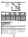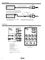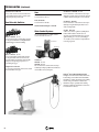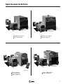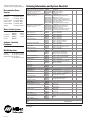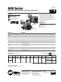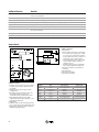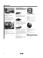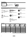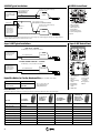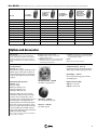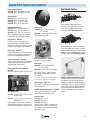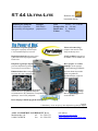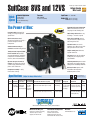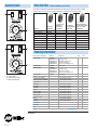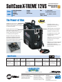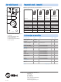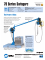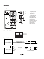
1
22A 24 Volt, Constant-Speed Wire Feeder Index No. M/11.0 Issued Dec. 1999 Processes Simple to use but with all the features needed for the industrial manufacturing and fabricating markets. Built with the strength and flexibility to handle strenuous work loads, the 22A delivers proven reliability and economy. MIG (GMAW) Welding Flux Cored (FCAW) Welding (Gas- and Self-shielded) This wire feeder is ideal for most high-duty-cycle applications requiring day-in day-out trouble-free operation. Applications Light-duty fab shops Trailer manufacturers Furniture manufacturers Automotive products Educational institutions Features Benefits Increased wire-feed-speed range The 22A wire-feed-speed range is 75 – 750! This offers a wider operating range than the competition. Trigger hold control Allow operator to make long extended welds without having to hold gun trigger. Gear-driven drive rolls Offers smooth, positive and accurate wire feed with long, uninterrupted service life. On-board burnback and motor ramp control Unmatched starting and stopping performance on a variety of power sources. This helps to ensure positive arc starting performance. 16 gauge sheet metal housing Robust in rough service applications. Less prone to damage. Optional presettable voltage and wire feed speed Allows voltage and wire feed speed to be preset and monitored. Does not require a volt sense lead. Miller’s True Blue® Warranty Wire feeder is warranted for 3 years — parts and labor. Typical Installation See back cover for complete system checklist. Miller CV or CV/CC power source equipped with a 14-pin receptacle and 24 VAC power. 10 ft (3 m) 24 VAC and contactor cord supplied with feeder Note: For power sources only supplying 115 VAC power the R-115 (#193 164) model is recommended. Specifications (Subject to change without notice.) Industrial (Use with CV Power Sources.) Input Power Electrode Wire Diameter Capacity Wire Speed Dimensions Net Weight 24 VAC, 7 A, 50/60 Hz .023 – 5/64 in (0.6 – 2.0 mm) 75 – 750 IPM (1.9 – 19 m/min) H: 11 in (279 mm) W: 10-3/4 in (273 mm) D: 23-1/2 in (597 mm) 36 lb (15.4 kg) ® Certified by Canadian Standards Association to both Canadian and U.S. Standards. NRTL/C Ordering Information ☞ See back page. Miller Electric Mfg. Co. International Headquarters Web Site An Illinois Tool Works Company 1635 West Spencer Street Appleton, WI 54914 USA Phone: 920-735-4505 USA FAX: 920-735-4134 Canadian FAX: 920-735-4169 International FAX: 920-735-4125 www.MillerWelds.com Control Panel 1. Gun Connection 2. Trigger Receptacle 3. Voltage/Wire Speed Meter* 4. Meter Selection Switch* 5. Remote Voltage Control* 6. Wire Speed Control 7. Jog/Purge 8. Trigger hold (On/Off) 3 4 5 Power On/Off (on rear panel) *Optional 6 1 2 7 8 Drive Roll Kits (Order from Miller Service Parts.) Select drive roll kits from chart below according to type and wire size being used. Drive roll kits include the necessary guides and feature an anti-wear sleeve for inlet guide. Wire size “V” groove for hard wire “U” groove for soft wire or soft-shelled cored wires “V” knurled for hard-shelled cored wires “U” cogged for extremely soft wire or softshelled cored wires (i.e., hard facing types) .023 / .025 in (0.6 mm) #087 131 — — .030 in (0.8 mm) #079 594 — — — — .035 in (0.9 mm) #079 595 #044 749 #079 606 — .040 in (1.0 mm) #161 189 — — — .045 in (1.1/1.2 mm) #079 596 #079 599* #079 607 #083 318 .052 in (1.3/1.4 mm) #079 597 #079 600 #079 608 #083 317 1/16 in (1.6 mm) #079 614 #079 598 #079 601 #079 609 .068/.072 in (1.8 mm) — — #089 984 — 5/64 in (2.0 mm) — #079 602 #079 610 #079 615 *Accommodates .045 and .047 (3/64) wires. Nylon Wire Guides for Feeding Aluminum Wire (Order from Miller Service Parts.) Wire Size .035 – .047 in (1.2 mm) 1/16 in (1.6 mm) Inlet Guide #151 203 #151 205 Note: “U” groove drive rolls are recommended when feeding aluminum wire. Options 2 Skill Level Index The bracketed entry to the right of the stock number of field-installed options contains a letter and number. The letter indicates the skill level required to install the option. The number indicates the approximate time required for installation (see legend). A– Easy. No previous experience needed. B– Average. Requires removal of service panels. Mechanical ability is helpful. C– Difficult. May require the use of an ohmmeter and/or splicing of electrical wires. Repair or replacement of component parts is more difficult. D– Technical. May require the use of an ohmmeter and the ability to read a circuit diagram. Repair or replacement of component parts is complex. Digital Display V/WFS #186 498 Field [ B: 30 ] Dual-function, back-lit LCD digital meter with selector switch. The digital meter allows the wire feed speed to be preset in inches per minute or meters per minute. The voltage function, if used with a current manufactured Miller electronically controlled constant voltage power source, allows the arc voltage to be preset and monitored on the digital display. When used with voltage control #194 211. Voltage Control #194 211 Field [ A: 15 ] Installs in front panel of the feeder to allow remote voltage control of most Miller electrically controlled CV or CC/CV power sources. Preflow/Postflow and Spot Control #186 496 Field [ A: 25 ] Installs inside feeder under an easy access hinged cover. Provides up to 5 seconds of spot weld time and has adjustable timers (0.25 to 5 seconds) for controlling gas flow prior to arc initiation and after completion of weld. Note: The field kit voltage control includes a 10 ft (3 m) cord that replaces the standard cord supplied with the feeder. Run-In Control #193 391 Field [ A: 25 ] A separate wire feed speed adjustment to control wire speed prior to arc initiation. This control may be beneficial to aid arc starting with certain types of power sources. Example: [ B: 30 ] Skill Level: B, Time: 30 minutes Accessories Carrying Handle Feeder Cart Blue Runner #043 965 Simple, convenient, and easy-to-assemble running gear for the XMT-304 and Invision 354MP. Designed for factory floor MIG applications using the 22A or S-60 Series wire feeders. Carrying Handle #193 762 For lifting and moving feeder. (Cannot be used with wire reel assembly #108 008.) Hanging Bail Reel or Spool Cover Extension Cords #122 973 25 ft (7.6 m) #122 974 50 ft (15 m) #122 975 75 ft (23 m) These extension cords can be added to the standard 10 ft cord to extend feeder farther from the power source. Hanging Bail #058 435 [ A: 05 ] Suspends feeder over the work area. Carrying Cart #056 301 [ A: 30 ] A utility cart for the wire feeder and other miscellaneous welding supplies. Height: 34 in (863 mm) Lower tray height: 9 in (228 mm) Shipped disassembled. Reel Cover #058 256 For 60 lb (27.2 kg) coil. PSA-2 Control #141 604 [ A: 10 ] Required when using the 22A wire feeder with power sources having only 115 VAC available. The PSA-2 control can be conveniently mounted on the wire feeder or positioned at the power source. The control is equipped with a 14-pin receptacle for direct connection of the wire feeder control cord. A short cord with a 4-pin Amp plug is hard wired to the control. A 10 ft (3 m) interconnecting cord with a 4-pin Amp for connection to the PSA-2 and Hubbell connectors for older-style Miller CV power sources is included. The PSA-2 control can also be used with competitive power sources requiring a contact closure for contactor control. [ A: 05 ] 2/0 MIG Welding Accessory Kit #173 856 25 ft (7.6 m). Includes gas hose, weld cable and ground cable with clamp. Spool Cover #057 607 [ A: 05 ] For 12 in (304 mm) spool. M-25 and M-40 Guns See Lit. Index No. M/10.0. Wire Reel Assembly GW-500 Gun See Lit. Index No. M/13.4. Turntable Assembly Feeder Cart #142 382 [ A: 20 ] A low-profile, creeper cart which allows the operator to easily move the feeder around the work area. Shipped disassembled. Wire Reel Assembly #108 008 [ A: 05 ] For 60 lb (27.2 kg) coil of wire. (Cannot be used with carrying handle #193 762.) Turntable Assembly #146 236 [ B: 20 ] Allows rotation of feeder as operator changes work positions. This reduces strain and bending on gun cable. Spool Adapter #047 141 [ A: 05 ] For use with 14 lb (6.4 kg) spool of Lincoln self-shielding wire. 3 System Checklist and Quotation Sheet Equipment and Options Stock No. Description 22A #193 066 #193 066-01-1 #193 066-02-2 With run-in control With digital display and voltage control Digital Display Meter #186 498 Field Voltage Control #194 211 Field Run-In Control #193 391 Field Preflow/Postflow and Spot Control #186 496 Field Drive Roll Kit Qty. See table on page 2 Power Sources Regency 250 Package See Lit. Index No. DC/12.6 CP-302 See Lit. Index No. DC/13.0 CP-252TS See Lit. Index No. DC/13.0 Deltaweld 302 See Lit. Index No. DC/16.2 Shopmaster See Lit. Index No. AD/2.3 XMT-304 CC/CV See Lit. Index No. DC/18.8 Invision 354 MP See Lit. Index No. DC/23 Accessories Blue Runner #043 965 Carrying Cart #056 301 Feeder Cart #142 382 Carrying Handle #193 762 Hanging Bail #058 435 Reel Cover #058 256 For 60 lb coil Spool Cover #057 607 For 12 in spool Wire Reel Assembly #108 008 Turntable Assembly #146 236 Spool Adapter #047 141 PSA-2 Control #141 604 Extension Cords #122 973 #122 974 #122 975 2/0 MIG Accessory Kit #173 856 Interconnecting Cable #043 695 #043 696 #043 697 For 14 lb spool of Lincoln self-shielding wire 25 ft 50 ft 75 ft 10 ft 25 ft 75 ft M-25 and M-40 MIG Guns See Lit. Index No. M/10.0 GW-500 MIG Gun See Lit. Index No. M/13.4 Miscellaneous Primary Power Cable Secondary Weld Cable Ground Cable with Work Clamp Gas Cylinder Gas Hose with Fittings Regulator/Flowmeter Welding Wire Helmet Welding Gloves Date: Distributed by: Litho in USA Total Quoted Price: Price 60 Series Single and Dual Semiautomatic, Constant-Speed Wire Feeders Processes Index No. M/2.0 Issued June 2001 Outstanding performance in the most demanding MIG applications—that’s the 60 Series heavy-duty wire feeder. Designed with flexibility in mind, the 60 Series offers multiple configurations. A customer can start with a simple system, and add options as welding needs change. Performance and flexibility meet virtually every job requirement with the 60 Series. MIG (GMAW) Welding Flux Cored (FCAW) Welding (Gas- and Self-shielded) Applications Heavy equipment manufacturing Automotive products Rail car Heavy steel fabricators Agricultural S-60 Model D-60 Model Features Benefits New! A separate wire feed adjustment to control wire speed prior to arc initiation. Optional run-in control Tank manufacturing Industrial equipment manufacturing Commercial equipment manufacturing Trailer manufacturing Unique Posifeed™ wire drive system Provides positive wire feeding performance. Easy loading and threading of welding wire Wire threads easily through drive system without having to release the drive roll pressure arm. Rotatable drive assembly Reduces sharp bends in the gun cable. Improves wire feeding performance and extends the service life of the gun liner. Solid-state speed control and brake circuit Excellent speed control and regulation. Eliminates the need for electrical/mechanical relays. Increased service life. Two sealed ball bearing all-gear-driven drive-roll carriers Offers a smooth, positive and accurate wire feed with long uninterrupted service life. Quick-change drive rolls No tools required to change or service drive rolls. Gas purge control Purges gas line without feeding wire. Wire jog control Feeds welding wire without energizing contactor. Quick-release, calibrated drive-roll pressure-adjustment arm Allows drive roll change without losing spring preload setting. Reduced weld cycle time. Two to four drive roll conversion Allows two-drive-roll feeder to be quickly, easily and economically converted to a four-drive-roll feeder. (Requires optional Drive Roll Conversion Kit.) Accommodates a variety of internally installed, plug-in options Easy to upgrade feeder as the customers needs and requirements change. Optional trigger hold Reduces fatigue by allowing the operator to weld without holding the gun trigger. Specifications (Subject to change without notice.) * Input Power Electrode Wire Diameter Capacity Wire Speed 24 VAC, 10 A, 50/60 Hz .023–1/8 in (0.6 – 3.2 mm) 50–780 IPM (1.3 –19.8 m/min) ® Heavy Industrial Dimensions S-60 D-60 H: 13-1/4 in (337 mm) W: 13 in (330 mm) D: 26-1/2 in (673 mm) H: 13-1/2 in (343 mm) W: 17-1/2 in (445 mm) D: 32-1/4 in (819 mm) Net Weight S-60 D-60 43 lb (19.5 kg) 74 lb (33.6 kg) Certified by Canadian Standards Association to both Canadian and U.S. Standards. NRTL/C ** 50/60 Hz models with CE Specifications are manufactured according to the Standards IEC-974-1 and EN-60974-1. Ordering Information (Use with CV Power Sources.) ☞ See back page. Miller Electric Mfg. Co. International Headquarters Web Site An Illinois Tool Works Company 1635 West Spencer Street Appleton, WI 54914 USA Phone: 920-735-4505 USA FAX: 920-735-4134 Canadian FAX: 920-735-4169 International FAX: 920-735-4125 www.MillerWelds.com Typical Installations Miller electrically controlled CV and CC/CV power source with a 14-pin receptacle and 24 VAC supply Basic or D* Model 10 ft (3 m) 24 VAC, Contactor and Voltage Control Cord (supplied with feeder) 10 ft (3 m) interconnecting cord included with PSA-2 control. Includes a 4-pin Amp connector for connecting to PSA-2 control and Hubbell connectors on older-style Miller CV power sources. Optional PSA-2 Control *When using the D model with Miller power sources that DO NOT have remote voltage control capabilities, i.e., CP type, the voltage control in the feeder IS NOT functional. Basic or D* Model 4-Pin Amp Miller CV or competitive CV power source with only 115 VAC power or competitive power source requiring contact closure for contactor control 1ft (305 mm) Note: If using the S-60 or D-60 with a power source having only 115 VAC supply, the PSA-2 (Power Source Adapter) is required. When using the PSA control, optional remote voltage is not functional. Control Panels Single 60 Series Dual 60 Series 4 5 6 1 7 2 3 8 9 S-62 and S-64 1. Trigger Hold Control*† 2. Jog/Gas Purge Switch 3. Trigger Receptacle 4. Voltage and Wire Speed Meters* 5. Wire Speed Control 6. Voltage Control* 7. Wire Feed Speed 8. Voltage Control for Dual Schedule* 9. Press to Set Schedule B* Note: Power on/off switch is on back panel Dual model trigger hold located on side panel † *Optional 2 D-64 D-64 (dual) models have two sets of the controls. Posifeed Wire Drive Assembly Features 24 VDC high-torque, permanent-magnet motor. Quick-change drive rolls. Quick-release, calibrated drive roll pressure adjustment arm allows drive roll change without losing spring preload setting. Simple conversion from two-drive-roll to four-drive-roll feeder Rotatable drive assembly helps eliminate sharp bend in gun cable. Four-Drive-Roll Model Easy loading and threading of welding wire. Uses Miller standard 1-5/8 in (41 mm) diameter drive rolls. Quick-connect for all Miller guns Drive assembly rotated. Covered drive rolls — easy access, heavy-duty, molded composite cover over drive assembly. Floating positive drive systems provide trouble-free feeding on a variety of wires. Drive Roll Kits (Order from Miller Service Parts.) Select drive roll kits from chart below according to type and wire size being used and the type of wire drive assembly (two-drive-roll or four-drive-roll system). Drive roll kits include the necessary guides and feature an anti-wear sleeve for inlet guide. Wire size “U” groove for soft wire or soft-shelled cored wires “V” groove for hard wire “U” cogged for extremely soft wire or softshelled cored wires (i.e., hard facing types) “V” knurled for hard-shelled cored wires 2 Rolls 4 Rolls 2 Rolls 4 Rolls 2 Rolls 4 Rolls 2 Rolls 4 Rolls .023 / .025 in (0.6 mm) #151 030 #151 024 — — — — — — .030 in (0.8 mm) #151 031 #151 025 — — — — — — .035 in (0.9 mm) #151 032 #151 026 #151 044 #151 036 #151 061 #151 052 — — .040 in (1.0 mm) #161 189 #161 190 — — — — — — .045 in (1.1/1.2 mm) #151 033 #151 027 #151 045* #151 037* #151 062 #151 053 #151 077 #151 070 .052 in (1.3/1.4 mm) #151 034 #151 028 #151 046 #151 038 #151 063 #151 054 #151 078 #151 071 1/16 in (1.6 mm) #151 035 #151 029 #151 047 #151 039 #151 064 #151 055 #151 079 #151 072 .068/.072 in (1.8 mm) — — — — #151 065 #151 056 — — 5/64 in (2.0 mm) — — #151 048 #151 040 #151 066 #151 057 #151 080 #151 073 3/32 in (2.4 mm) — — #151 049 #151 041 #151 067 #151 058 #151 081 #151 074 7/64 in (2.8 mm) — — #151 050 #151 042 #151 068 #151 059 #151 082 #151 075 1/8 in (3.2 mm) — — #151 051 #151 043 #151 069 #151 060 #151 083 #151 076 *Accommodates .045 and .047 (3/64 in) wire Nylon Wire Guides for Feeding Aluminum Wire Wire Guides (Order from Miller Service Parts.) Wire Size .047 in (1.2 mm) 1/16 in (1.6 mm) 3/32 in (2.4 mm) Inlet Guide #151 203 #151 205 #151 207 Intermediate Guide #151 204 #151 206 #151 208 Note: “U” groove drive rolls are recommended when feeding aluminum wire. Wire Size .023 – .040 in (0.6 – 1.0 mm) .045 – .052 in (1.1 – 1.4 mm) 1/16 – 5/64 in (1.6 – 2 mm) 3/32 – 7/64 in (2.4 – 2.8 mm) 1/8 in (3.2 mm) Inlet Guide #150 993 #150 994 #150 995 #150 996 #150 997 Intermediate Guide #149 518 #149 519 #149 520 #149 521 #149 522 3 Options Skill Level Index The box to the right of the stock number of field-installed options contains a letter and number. The letter indicates the skill level required to install the option. The number indicates the approximate time required for installation (see legend). A– Easy. No previous experience needed. B– Average. Requires removal of service panels. Mechanical ability is helpful. C– Difficult. May require the use of an ohmmeter and/or splicing of electrical wires. Repair or replacement of component parts is more difficult. Digital Meters with Presettable WFS and Voltage Control For S-60 model #180 313 Field [ B: 45 ] For D-60 model #180 315 Field [ B: 1:20 ] Meters use a back-lit liquid crystal display which are easy to read in virtually any lighting condition. The display and the ten-turn potentiometers allow the power source voltage and wire feed speed to be accurately preset on the digital meters. Once the arc is established, actual arc voltage and wire feed speed is displayed. Digital Dual Schedule Control For S-60 model #173 751 Field [ B: 40 ] For right side of D-60 model #172 826 Field [ B: 40 ] For left side of D-60 model #173 749 Field [ B: 20 ] Allows two separate welding conditions (voltage and wire feed speed) to be used with one wire. The parameters can be accurately preset on the digital meters. Note: This option is compatible with the following Miller electronically controlled CV or CC/CV power sources: Power Source Effective Serial No. Invision all Phoenix all XMT 304 all Deltaweld (any) serial no. KG141349 and newer Dimension serial no. KG253517 and newer Maxtron 450 serial no. KG111783 For power sources manufactured prior to these serial numbers, and for any Dimension power sources, please consult the factory. For mechanically controlled power sources, such as the CPs, the voltage control is not functional. Digital Voltage Control For S-60 model [ B: 20 ] #134 382 For D-60 model [ B: 25 ] #138 549 Digital Meters (With wire feed speed) For S-60 model [ B: 45 ] #172 734 For D-60 model [ B: 1: 20 ] #172 735 New! Run-In Control For S-60 model [ A: 25 ] #194 682 For left or right side For D-60 model [ A: 50 ] #194 680 A separate wire feed adjustment to control wire speed prior to arc initiation. Ground Current Sensor #160 963 Required when connecting to Deltaweld prior to KG141349 or Dimension prior to KG253517 or Maxtron KG111783. 4 Note: The Digital Meters option (listed above) is required to install the Digital Dual Schedule Control. Select an appropriate Dual Schedule Switch (see Accessories). Voltage Control (Non-Digital) For S-60 model #133 425 Field [ A: 10 ] For D-60 model #138 527 Field [ A: 10 ] Installs in front panel of feeder to allow remote voltage control of Miller electrically controlled CV or CC/CV power sources having a 14-pin receptacle. S-model trigger hold control on front panel 4-in-1 Control For S-60 model #132 138 Field [ A: 15 ] For left or right side of D-60 model #138 543 Field [ A: 15 ] Includes: spot/burnback and preflow/ postflow. This control is mounted on an inside panel and includes 0 (zero) to 5 second gas preflow and postflow control, up to 5 seconds of spot weld time, and up to 0.25 seconds of burnback control. D– Technical. May require the use of an ohmmeter and the ability to read a circuit diagram. Repair or replacement of component parts is complex. Example: [ B: 30 ] Skill Level: B, Time: 30 minutes Control Detachment Kit ( installed only) For S-60 model #134 936 Field 10 ft (3 m) #134 937 Field 25 ft (7.6 m) [ B: 55 ] For D-60 model #134 935 Field 25 ft (7.6 m) [ B: 1:00 ] Allows separation of the control module from the wire drive assembly and base. Drive Roll Conversion Kit For feeder manufactured with serial number KE-756284 or newer. #172 104 [ A: 10 ] For feeder manufactured prior to serial number KE-756284. #132 128 [ A: 10 ] Allows an existing S-62 or D-62 to be easily converted from a two-drive-roll to a four-driveroll feeder. (Must order one kit for each side of dual models.) Water Flow Shutdown Switch #180 390 Coolant protects the water-cooled gun from overheating if water is not present or stops flowing to the gun. Burnback Control For S-60 model [ A: 20 ] #132 140 For left or right side of D-60 model [ A: 20 ] #138 541 Burnback control up to 0.25 seconds Trigger Hold For S-60 model #189 893 Field [ A: 15 ] For D-60 model #189 894 Field [ A: 20 ] Allows the operator to make long, extended welds without having to hold the gun trigger. Accessories Process Selector Control #042 872 Allows you to easily change weld processes without changing cables — from TIG to MIG or TIG to Stick. Can also connect two wire feeders with one power source. Carrying Cart #056 301 [ A: 30 ] A utility cart for the wire feeder and other miscellaneous welding supplies. Height: 34 in (863 mm) Lower tray height: 9 in (228 mm) Shipped disassembled. Feeder Cart #142 382 [ A: 20 ] A low-profile, creeper cart which allows the operator to easily move the feeder around the work area. Shipped disassembled. Wire Straightener For .035–.045 in (0.9–1.1 mm) dia. wire #141 580 [ A: 05 ] For 1/16–1/8 in (1.6–3.2 mm) dia. wire #141 581 [ A: 05 ] Helps reduce the cast in wire to improve wire feeding performance and increase the service life of the gun liner and contact tip. Spool Covers For S-60 and left side of D-60 model #057 607 For right side of D-60 model #090 389 For 12 in (305 mm) spool. 2/0 MIG Welding Accessory Kit #194 779 10 ft (3.1 m) #173 856 25 ft (7.6 m) #173 851 50 ft (15.2 m) Includes gas hose, weld cable and ground cable with clamp. Polarity Reversing Isolation Control For D-60 model only. #042 871 [ A: 15 ] A dual-function control designed for use with the D-60 dual-wire feeder or any application where electrical isolation and/or polarity reversing capabilities are required. For example, one wire of the D-60 feeder can be electrically cold while welding with the other wire. The wires can also be run on opposite or the same polarity (straight or reverse). Both functions can be performed at the same time. Note: Includes bracket to mount control on top of dual feeder. Extension Cords #122 973 25 ft (7.6 m) #122 974 50 ft (15.2 m) #122 975 75 ft (23 m) Provides 14-pin, 24 VAC, contactor and voltage control. Add to the standard 10 ft (3 m) feeder cord to extend feeder farther from power source. Turntable Assembly #146 236 [ B: 20 ] Allows rotation of the feeder as the operator changes work positions. Reduces strain and bending on the gun cable. Wire Reel Assembly #108 008 For 60 lb (27 kg) coil of wire. Reel Covers For S-60 and left side of D-60 model #058 256 For right side of D-60 model #091 668 For 60 lb (27 kg) coil. Helps to protect the welding wire from dust and other contaminants. Note: Reel and Spool Covers cannot be installed if the wire drive assembly is in a rotated position. Compression Spring #057 745 Required when using 8 in (203 mm) diameter 10 lb (4.5 kg) and 15 lb (6.8 kg) spools of wire. Hanging Bail (Electrically Isolated) #058 435 [ A: 05 ] Used for suspending feeder over work area. Spool Adapter #047 141 For use with 14 lb (6.4 kg) spool of Lincoln self-shielding wire. PSA-2 Control #141 604 [ A: 10 ] Required when using the S-60 and D-60 wire feeders with power sources having only 115 VAC available. The PSA-2 control can be conveniently mounted on the wire feeder or positioned at the power source. The control is equipped with a 14-pin receptacle for direct connection of the wire feeder control cord. A short cord with a 4-pin Amp plug is hard wired to the control. A 10 ft (3 m) interconnecting cord with a 4-pin Amp for connection to the PSA-2 and Hubbell connectors for olderstyle Miller CV power sources is included. The PSA-2 control can also be used with competitive power sources requiring a contact closure for contactor control. 5 Accessories (Continued) Extension Cord #047 813 25 ft (7.6 m). Can be used to extend the 10 ft cord supplied with the PSA-2 control (4-pin Amp to 4-pin Amp connection). Dual Schedule Switches For use with digital dual schedule control. Guns Coolmate V3 #043 009 115 VAC For use with water-cooled torches rated up to 500 amps. Vertical design conveniently mounts to Miller cylinder rack in place of one cylinder. GW-500 Gun See Lit. Index No. M/13.4 M-25, M-40 Guns See Lit. Index No. M/10.0 International Gun Adapter #164 902 Water Coolant Systems DSS-8 #079 693 [ A: 05 ] A two-position trigger switch which attaches to the gun handle and is used in place of the standard trigger for dual scheduling. For more information, see Miller Coolant Systems Lit. Index No. AY/7.2. Coolmate V3 Coolmate 3 DSS-9 #071 833 [ A: 05 ] A two-position slide switch which attaches to the gun handle and is used to select the desired welding condition for dual schedule purposes. The gun trigger operates as a standard gun trigger. Adapter Cord #157 364 A 1 ft, Y-trigger cable that connects DSS switch and control box to the gun. Coolmate 4 #042 288 For use with water-cooled torches rated up to 600 amps. Tough molded polyethylene case with carrying handle. Coolant #043 810 Sold in cases of four 1-gallon recyclable plastic bottles. Miller coolants contain a base of ethylene glycol and deionized water to protect against freezing to -37˚F (-38˚C) or boiling to 227˚F (108˚C). Also contains a compound that resists algae growth. Coolmate 4 Coolmate 3 #043 007 115 VAC #043 008 230 VAC For use with water-cooled torches rated up to 600 amps. Unique paddle-wheel indicator, external filter and easy-fill spout. Swingarc™ Boom-Mounted Wire Feeders Swingarc boom-mounted semiautomatic wire feeders bring an extra dimension of flexibility and efficiency to high-production wire welding stations. You get an effective solution that maximizes output, especially when dealing with large weldments and hard-to-reach areas. See Lit. Index No. M/13.0. 6 Typical Systems for 60 Series Deltaweld 452 Dimension 452 S-62 D-64 Deltaweld® 452 #903 394 S-62 #131 785-02-44 Dimension™ 452 #903 255 D-64 #131 788-03-35 Invision 456MP XMT 304 S-64D D-64 Optima 304 XMT® 304 #903 471 D-64 #131 788-01-29 Optima™ 304 #043 186 Invision™ 456MP #903 725 S-64D #131 786-02-46 7 Important note: Digital feeders require solid-state machine for optimum performance. Recommended Power Sources Deltaweld® Dimension XMT® 304 Invision™ 354 MP Invision™ 456P Invision™ 456MP XMT 456 Lit. Index No. DC/16.2 Lit. Index No. DC/19.2 Lit. Index No. DC/18.8 Lit. Index No. DC/23 Lit. Index No. DC/20 Lit. Index No. DC/23 Lit. Index No. DC/18.8 Ordering Information and System Checklist Equipment and Options Stock No. Description S-62 Single-wire, Two-drive-roll Models (Order drive rolls and wire guides separately. See page 3.) S-64 Single-wire, Four-drive-roll Models (Order drive rolls and wire guides separately. See page 3.) #131 785 #131 785-01-39 #131 785-02-39 #131 786 #131 786-01-26 #131 786-01-32 #131 786-01-37 #131 786-02-46 #131 786-02-52 #131 786-03-43 #131 786-02-44 #131 786-03-45 #131 788 #131 788-01-29 #131 788-01-30 #131 788-01-36 #131 788-03-35 #131 788-03-42 #180 313 #180 315 #134 382 #138 549 #172 734 #172 735 #173 751 #172 826 #173 749 #133 425 #138 527 #132 138 #138 543 #194 682 #194 680 #160 963 #134 936 #134 937 #134 935 #132 128 #172 104 #180 390 #132 140 #138 541 #189 893 #189 894 Basic Model New! w/Run-In Control w/CE and Euro Adapter Basic Model w/High-Speed Motor w/Digital Display and Voltage Control New! w/Run-In Control w/Digital Display and Digital Dual Schedule w/High-Speed Motor and Digital Display w/CE, High-Speed Motor and Euro Accessory Kit w/CE, and Euro Adapter w/CE, Digital Display and Euro Adapter Basic Model w/Digital Display and Voltage Control w/High-Speed Motor (left side only) New! w/Run-In Control w/Digital Display and Digital Dual Schedule w/CE, Digital Display and Euro Adapter Field. For S-60 model Field. For D-60 model Field. For S-60 model Field. For D-60 model Field. For S-60 model Field. For D-60 model Field. For S-60 model Field. For right side of D-60 model Field. For left side of D-60 model Field. For S-60 model Field. For D-60 model Field. For S-60 model Field. For left or right side D-60 model Field. For S-60 model Field. For D-60 model D-64 Dual-wire, Four-drive-roll Models (Order drive rolls and wire guides separately. See page 3.) Water Coolant Systems Coolmate 3 Coolmate V3 Coolmate 4 Coolant #043 007 #043 008 #043 009 #042 288 #043 810 115 VAC 230 VAC 115 VAC 115 VAC Swingarc™ Mounting Equipment See Lit. Index No. M/13.0 Digital Meters with Presettable WFS and Voltage Control Digital Voltage Control Digital Meters Digital Dual Schedule Voltage Control (Non-Digital) 4-in-1 Control New! Run-In Control MIG Welding Guns Ground Sensor Control Control Detachment Kit GW-500 See Lit. Index No. AY/18.0 M-25, M-40 See Lit. Index No. AY/15.0 Roughneck C-Series (300 – 600 A) See Lit. Index No. AY/17.0 Drive Roll Conversion Kit Waterflow Shutdown Switch Burnback Control Trigger Hold Accessories Carrying Cart Feeder Cart Turntable Assembly Hanging Bail Wire Straightener Spool Covers Wire Reel Assembly Reel Covers Compression Spring Spool Adapter Process Selector Control 2/0 MIG Welding Accessory Kit Polarity Reversing Isolation Control Extension Cords PSA-2 Control PSA-2 Extension Cord Dual Schedule Switches Cord, Y-Adapter Adapter, International Gun Date: Distributed by: Litho in USA #056 301 #142 382 #146 236 #058 435 #141 580 #141 581 #057 607 #090 389 #108 008 #058 256 #091 668 #057 745 #047 141 #042 872 #194 779 #173 856 #173 851 #042 871 #122 973 #122 974 #122 975 #141 604 #047 813 #079 693 #071 833 #157 364 #164 902 Qty. Field. 10 ft (3 m), for S-60 model Field. 25 ft (7.6 m), for S-60 model Field. 25 ft (7.6 m), for D-60 model Field. For serial nos. before KE-756284 Field. For serial nos. after KE-756284 Field. For S-60 model Field. For D-60 model, Left or right side Field. For S-60 model Field. For D-60 model Electrically isolated For .035 – .045 in (0.9 – 1.1 mm) diameter wire For 1/16 – 1/8 in (1.6 – 3.2 mm) diameter wire For S-60 and left side of D-60 model For right side of D-60 model For S-60 and left side of D-60 model For right side of D-60 model 10 ft (3.1 m) 25 ft (7.6 m) 50 ft (15.2 m) For D-60 model 25 ft (7.6 m) 50 ft (15.2 m) 75 ft (23 m) 25 ft (7.6 m). For use with PSA-2 control DSS-8 DSS-9 Total Quoted Price: Price Index No. M/2.4 Issued Oct. 2000 60M Series Single and Dual, Programmable, Constant-Speed Wire Feeders The 60M Series of semiautomatic wire feeders offers the ultimate in versatility and performance. Designed for pulse MIG and semiautomatic welding, all 60M models are equipped with eight synergic pulse programs. The dual models can perform the same process on both sides, or one can be used for conventional MIG, and the other used for pulsed MIG welding. Processes MIG (GMAW) and Pulsed MIG (GMAW-P) Welding Flux Cored (FCAW) Welding (Gas and Self-shielded) Applications S-60M Model Metal fabrication Heavy manufacturing Construction Light manufacturing D-60M Model Features New! New! Benefits SharpArc™ Technology An arc control that offers a simple way to tailor factory weld programs to accommodate a variety of welding applications. Start/Crater Ramp Allows the output power to be tapered from start to weld and from weld to crater. Microprocessor-based design Flexible system with many standard features that can be customized for a variety of applications. Digital control Offers precise control and regulation of the welding arc not found in conventional systems. User-friendly front panel One simple and easy control for setting weld parameters. Two back-lit liquid crystal displays Easy-to-set and view all welding parameters and selectable features. 16 built-in synergic pulse programs Quick and easy selection of the right pulse program based on your wire and gas. Eight programs each for the Invision 456P and XMT 304. New! Power source selectable No setup card required for the Invision 456P or XMT 304. 16 programs are stored in the software. Just select either power source and do a system reset. Teach mode for pulse programs Allows easy field modification of pulse programs to meet your specific application. Full-featured, adjustable weld sequence control You can select and adjust any parameter within the weld sequence — preflow, run-in, weld time, crater, burnback and postflow, as required. ☞ See page 2 for additional features and benefits. Specifications (Subject to change without notice.) Model S-60M (Single) Input Power Electrode Wire Diameter Capacity Wire Speed 24 VAC 50/60 Hz .023–1/8 in (0.6–3.2 mm) 50–780 IPM (1.3–19.8 m/min.) Heavy Industrial Peak Voltage Range* Peak Current Range* Background Pulses per Current Range* Second* 0–99.9 V 100–600 A 0–200 A 20–400 PPS D-60M (Dual) Pulse Width* Dimensions Net Weight 1.0–5.0 Milliseconds H: 14 in (356 mm) W: 14 in (356 mm) D: 26-1/2 in (673 mm) 58 lb (26 kg) H: 14-3/4 in (375 mm) W: 18 in (457 mm) D: 32 in (813 mm) 82 lb (37 kg) *Applies only when 60M feeders are used with the Invision® 456 and Phoenix ™ 456 power sources. Ordering Information (Use with CC/CV Power Sources.) ☞ See back page. Miller Electric Mfg. Co. International Headquarters Web Site An Illinois Tool Works Company 1635 West Spencer Street Appleton, WI 54914 USA Phone: 920-735-4505 USA FAX: 920-735-4134 Canadian FAX: 920-735-4169 International FAX: 920-735-4125 www.MillerWelds.com Additional Features Benefits Programmable security system Consistent results are possible by programming limits to the range of parameter adjustments. Eliminates inadvertent changes of preset parameters. Dual schedule capabilities Allows two separate welding conditions to be programmed for one wire. Arc time totalizer and cycle counter Handy feature for conducting job studies and maintenance schedules. Electronic trigger hold control Allows the operator to make long extended welds without holding gun trigger. Gas purge and wire jog control Purge gas line and feed wire without energizing system. Quick-change drive rolls Gear-driven drive rolls are easy to change. No tools required. Rotatable wire drive assembly Eliminates sharp bends in the gun cable, thus improving wire feed performance and extending the service life of the gun liner. (Bench models only.) Sealed ball bearing, all-gear driven system Smooth, positive and accurate wire feed offers long, uninterrupted service life. Posifeed™ wire drive system Four drive roll provides excellent feeding of welding wire. Control Panels 60M Series Side Panel 1. Mode Displays. 4 5 5 1 1 6 2 3 2 6 2. Mode Select Button. Provides choice of four modes: • Process Mode. (Pulse, adaptive pulse, or MIG.) Also used to teach customized pulse programs. • Sequence Mode. Allows variety of sequences in weld program. (Refer to Sequence Chart.) • Dual Schedule Mode. Links two weld programs when two different welding conditions are required for one wire. • Card Mode. Writes programs to optional Data Card or reads programs from the Data Card. 3. Parameter Select Button. Selects parameter to be changed. 4. Parameter Display 5. Parameter Increase Button 6. Parameter Decrease Button 7 3 4 60M Series Front Panel 1. Parameter Select. Controls the selection of voltage or arc length, wire feed speed, program number, and also SharpArc™. 2. Purge Button. Purges gas line and gun without energizing feeder. 3. Gun Trigger Receptacle. Prewired for single- and dual-schedule operation. Receptacle will accommodate a variety of dual schedule switches. 4. Trigger Hold Button and Light. System remains energized when operator releases gun trigger—ideal when making extended welds. 5. Digital Display 6. Jog Button. Feeds wire without energizing the power source contactor and gas valve. (Independent control) 7. Display Control. Single-knob control for setting all adjustable, displayed parameters. 2 Sequence Chart Sequence Time Wire Feed Speed Voltage or Trim Preflow 0 – 9.9 sec. not active during preflow not active during preflow Run-in not active during run-in not active during run-in adjustable Start 0 – 2.5 sec. adjustable adjustable Weld* 0 – 25 sec. adjustable adjustable Crater 0 – 2.5 sec. adjustable adjustable Burnback 0 – 0.25 sec. not active during burnback adjustable (voltage only) Postflow 0 – 9.9 sec. not active during postflow not active during postflow *Inductance is adjustable in the MIG process mode only when using the Invision or Phoenix 456 power source. Description of Pulsed MIG Welding Process When pulsed MIG welding, the power source rapidly switches the output from high peak current to low background current in precisely regulated intervals. The peak current pinches off a spray-transfer droplet while the low background current “cools” the arc with little or no metal transfer. With proper adjustment of the pulse parameters, the pulsed MIG welding process can produce high-quality welds when using a broad range of material types, thicknesses, and joint configurations. Requires use of a Miller inverter power source. Amperage Pulses Per Second Pulse Width (milliseconds) Advantages of Pulsed MIG Process over MIG Spray Transfer and Short Arc Welding • Can use larger, more economical wire diameters • Reduces or eliminates spatter • Lower heat input; therefore, reduced distortion • Better out-of-position puddle control • Optimum bead shape and penetration • Potential reduction in fume particulate emission Note: For additional pulsed MIG information, order Miller Electric’s GMAW-P Pulsed Spray Transfer Process Guide (#168 336). A 4-volume video training package (#175 773) is also available. Peak Amperage (Current) • • • • What is Pulsed MIG Welding? Pulsed MIG Process Variables Pulsed MIG Equipment and Set -Up Pulsed MIG Operator Techniques Includes Pulsed Spray Transfer Process Guide (#168 336) Time Background Amperage (Current) Pulsed MIG Wave Form 60M Design Features Can be used with a variety of Miller power sources : For pulsed MIG/conventional MIG welding use the 60M with the Invision™ 456, Phoenix™ 456 CC/CV, or the XMT ® 304 CC/CV inverter power source. For conventional MIG welding only, the 60M can also be used with the Deltaweld® or Dimension™ Series power source. Programming Features Eight Synergic Pulsed MIG Programs factory-set for use with the XMT® 304 welding power source: Mild steel wire with Argon/CO2 shielding gas (1) .030 in (0.8 mm) (2) .035 in (0.9 mm) (3) .045 in (1.1 mm) Stainless steel wire with Argon/Helium/CO2 shielding gas (4) .030 in (0.8 mm) (5) .035 in (0.9 mm) (6) .045 in (1.2 mm) Nickel alloy wire with Argon/Helium shielding gas (7) .035 in (0.9 mm) Metal core wire with Argon/CO2 shielding gas (8) .045 in (1.2 mm) Eight Synergic Pulsed MIG Programs factoryset for use with the Invision™ 456 welding power source: Mild steel wire with Argon/CO2 shielding gas (1) .035 in (0.9 mm) (2) .045 in (1.2 mm) (3) .052 in (1.3 mm) (4) .062 in (1.6 mm) Stainless steel wire with Argon/Helium/CO2 shielding gas (5) .035 in (0.9 mm) (6) .045 in (1.2 mm) Metal core wire with Argon/CO2 shielding gas (7) .045 in (1.2 mm) (8) .052 in (1.3 mm) On-Board Programming and Diagnostics: • All factory-set synergic pulse programs can be modified to meet specific welding applications • Feeder can be manually programmed for the voltage and/or amperage range of the power source being used • Automatic shutdown if arc voltage is not detected when gun trigger is depressed • Automatic shutdown if no wire feed speed is present when the gun trigger is pressed • Drops out contactor and gas valve if arc is not sensed after 3 seconds Selectable Operating Features: • Feeder will compensate for variations in tip-to-work distance and provide a constant arc length (in Adaptive Pulse mode) • Arc voltage can be regulated at the power source output studs or at the welding gun • Gun trigger can be used to make program selection • Arc time counter accumulates and displays actual arc time (up to 9,999.99 hours) and weld cycles (up to 999,999 cycles). Counter can be reset to 0 (zero) as required. Ideal for job time studies, shift output, maintenance, etc. Security Capabilities: • Feeder can be programmed to limit the range of parameter control, the number of programs available, and the selectable parameters that are available to the operator • A three-digit code can be programmed to restrict unauthorized access to the set-up screen 3 Typical Installations Pulsed MIG or Conventional MIG Welding Invision 456, Phoenix 456 or XMT 304 power source (MIG or Pulse) 60M Feeder 10 ft (3 m) 14-pin cord (supplied with 60M feeder) Note: To connect the 60M feeder to an existing Maxtron ™ 450 power source use adapter cord #043 661. Conventional MIG Welding Miller electronically controlled CV or CC/CV power source with a 14-pin receptacle (MIG only) 60M Feeder 10 ft (3 m) 14-pin cord (supplied with 60M feeder) Four Roll Drive Roll Kits (Order from Miller Service Parts.) Select drive roll kits from chart below according to type and wire size being used. Drive roll kits include necessary guides and feature an anti-wear sleeve for the inlet guide. “U” cogged for extremely soft wire or softshelled cored wires (i.e., hard facing types) Wire size “V” groove for hard wire “U” groove for soft wire or soft-shelled cored wires “V” knurled for hard-shelled cored wires .035 in (0.9 mm) #151 026 #151 036 #151 052 — .040 in (1.0 mm) #161 190 — — — .045 in (1.1/1.2 mm) #151 027 #151 037 #151 053 #151 070 .052 in (1.3/1.4 mm) #151 028 #151 038 #151 054 #151 071 1/16 in (1.6 mm) #151 029 #151 039 #151 055 #151 072 .068/.072 in (1.8 mm) — — #151 056 — 5/64 in (2.0 mm) — #151 040 #151 057 #151 073 3/32 in (2.4 mm) — #151 041 #151 058 #151 074 7/64 in (2.8 mm) — #151 042 #151 059 #151 075 1/8 in (3.2 mm) — #151 043 #151 060 #151 076 Nylon Wire Guides for Feeding Aluminum Wire Wire Guides (Order from Miller Service Parts.) Wire Size .047 in (1.2 mm) 1/16 in (1.6 mm) 3/32 in (2.4 mm) Inlet Guide #151 203 #151 205 #151 207 Intermediate Guide #151 204 #151 206 #151 208 Note: “U” groove drive rolls are recommended when feeding aluminum wire. 4 Wire Size .023 – .040 in (0.6 – 1.0 mm) .045 – .052 in (1.1 – 1.4 mm) 1/16 – 5/64 in (1.6 – 2 mm) 3/32 – 7/64 in (2.4 – 2.8 mm) 1/8 in (3.2 mm) Inlet Guide #150 993 #150 994 #150 995 #150 996 #150 997 Intermediate Guide #149 518 #149 519 #149 520 #149 521 #149 522 Options Skill Level Index The bracketed entry to the right of the stock number of field-installed options contains a letter and number. The letter indicates the skill level required to install the option. The number indicates the approximate time required for installation (see legend). A– Easy. No previous experience needed. B– Average. Requires removal of service panels. Mechanical ability is helpful. C– Difficult. May require the use of an ohmmeter and/or splicing of electrical wires. Repair or replacement of component parts is more difficult. D– Technical. May require the use of an ohmmeter and the ability to read a circuit diagram. Repair or replacement of component parts is complex. Cord, Y-Adapter 24V #043 387 Connects an old feeder to a new power source. Digital Gas Flow Meter #186 313 [ B: 15 ] Allows gas flow rate (CFH) to be accurately set on the 60M front panel digital display. A programming feature in the 60M control allows a selectable gas range to be set and if for any reason the gas flow deviates from the set range the system will shut down and display a “GAS FLOW ERROR” on the 60M front panel display. This can be an excellent gas saver and will also alert to a low gas supply. Automation Upgrade Module #172 886 [ B: 15 ] This module consists of an I/O board and software upgrade that enables the 60M control to better communicate with other peripheral equipment and improves performance in an automatic welding cell. Weld Current Sensor #160 963 [ A: 05 ] This option is required when using M feeders with older style Miller CV power sources: Deltaweld® prior to serial no. KG141349 and Dimension™ prior to serial no. KC 253517. New! SharpArc™ Upgrade Kit #191 996 [ A: 15 ] This kit allows 60M feeders manufactured prior to serial no. KJ218744 to be upgraded to include the SharpArc feature. Blank Data Card #155 910 Stores up to 32 complete weld programs. Ideal for saving custom programs and transferring programs to other 60M feeders. Example: [ B: 30 ] Skill Level: B, Time: 30 minutes Features: two programmable outputs, remote start/stop, remote program select, arc voltage monitor, arc error monitor and wire stick check. Water Flow Shutdown Switch #180 390 [ A: 15 ] For use with the water hose kits. Protects water-cooled gun from overheating by shutting down system if water does not flow. If required on both sides of a dual model, two water flow shutdown switches must be ordered. Swingarc™ Boom-Mounted Wire Feeders Swingarc boom-mounted semiautomatic wire feeders bring an extra dimension of flexibility and efficiency to high-production wire welding stations. You get an effective solution that maximizes output, especially when dealing with large weldments and hard-to-reach areas. See Lit. Index No. M/13.0. 5 Accessories Dual Schedule Switches For use with dual schedule control. Dual schedule switches require adapter cord #157 364. Control Detachment Kit For S-60M model #134 936 Field 10 ft (3 m) [ B: 55 ] #134 937 Field 25 ft (7.6 m) [ B: 55 ] For D-60M model #134 935 Field 25 ft (7.6 m) [ B: 55 ] For 60M bench models only. Separates the feeder control module from the wire drive assembly and base. Ideal when using Automation Upgrade Module. DSS-8 #079 693 [ A: 05 ] A 15 ft two-position trigger switch that easily attaches to the welding gun. Use in place of the standard trigger for dual scheduling. DSS-9M #041 793 [ A: 05 ] A 15 ft, two-position slide switch that attaches to the welding gun. Selects welding condition when utilizing the dual schedule feature. Gun trigger operates as standard trigger. Wire Straightener For .035–.045 in (0.9–1.1 mm) wire #141 580 [ A: 05 ] For 1/16–1/8 in (1.6–3.2 mm) wire #141 581 [ A: 05 ] Reduces cast in wire. Improves wire feeding performance and increases life of gun liner and contact tip. DSS-10 Remote Increase/Decrease Switch #042 749 [ A: 05 ] A 15 ft, two-position, momentary contact switch that attaches to the welding gun. Use with the Remote Parameter Increase/Decrease feature to fine tune parameters at the welding gun while welding. Gun trigger operates as standard trigger. Adapter Cord #157 364 A 1 ft, Y trigger cable that connects DSS switch and control box to the gun. Required for use with dual schedule switches. 6 Wire Reel Assembly #108 008 Accommodates 60 lb (27 kg) coil of wire. Reel Covers For S-60M and left side of D-60M model #058 256 For right side of D-60M model #091 668 Accommodates 60 lb (27 kg) coil of wire. Protects wire from contaminants. Spool Covers For S-60M and left side of D-60M model #057 607 [ A: 05 ] For right side of D-60M model #090 389 [ A: 05 ] Fits a 12 in (304 mm) spool of wire. Guns M-40 Guns See Lit. Index No. M/10.0. Accessories Water Coolant Systems For more information, see Miller Coolant Systems Lit. Index No. AY/7.2. Coolmate V3 Coolmate 3 Carrying Cart #056 301 [ A: 30 ] Carries wire feeder and miscellaneous welding supplies. Height: 34 in (863 mm). Lower tray height: 9 in (228 mm). Shipped disassembled. Hanging Bail #058 435 [ A: 15 ] Electrically isolated. Suspends feeder over work area. Coolmate 4 Coolmate 3 #043 007 115 VAC #043 008 230 VAC For use with water-cooled torches rated up to 600 amps. Unique paddle-wheel indicator, external filter and easy-fill spout. Coolmate V3 #043 009 115 VAC For use with water-cooled torches rated up to 500 amps. Vertical design conveniently mounts to Miller cylinder rack in place of one cylinder. Coolmate 4 #042 288 For use with water-cooled torches rated up to 600 amps. Tough molded polyethylene case with carrying handle. Feeder Cart #142 382 [ A: 20 ] Low-profile, creeper cart. Shipped disassembled. Turntable Assembly #146 236 [ B: 20 ] Allows feeder to rotate as operator changes work position. Reduces strain and bending of gun cable. 14-Pin Extension Cords #043 690 25 ft (7.6 m) #043 691 50 ft (15 m) For optimum performance, do not extend 60M feeder more than 60 ft (18 m) from power source. Coolant #043 810 Sold in cases of four 1-gallon recyclable plastic bottles. Miller coolants contain a base of ethylene glycol and deionized water to protect against freezing to -37˚F (-38˚C) or boiling to 227˚F (108˚C). Also contains a compound that resists algae growth. Water Hose Kit #096 746 10 ft (3 m) [ A: 10 ] For 60M bench models only. Use with Miller coolant systems and water-cooled welding guns. Can be used with or without optional water flow safety switch. If water kit is to be used on both sides of a dual wire feeder, a kit must be ordered for each side of the feeder. 7 Recommended Power Sources MIG or Pulsed MIG Invision® 456P Lit. Index. No. DC/20 XMT® 304 CC/CV Lit. Index No. DC/18.8 Lit. Index. No. DC/21 Phoenix™ 456 MIG only Deltaweld® Dimension™ Lit. Index No. DC/16.2 Lit. Index No. DC/19.2 Ordering Information and System Checklist Equipment and Options Stock No. Description 60M Wire Feeder Note: Drive rolls must be ordered separately. #131 794* #131 794-01-3 #131 796* #131 796-02-1 #131 794-02-2 #131 794-03-2 S-64M, single S-64M, single, with high speed motor D-64M, dual D-64M, dual, with high speed motor (both sides) S-64M, with CE, Europe S-64M, with CE, Euro-French Drive Roll Kit Qty. See table on page 4 Wire Guides See table on page 4 Weld Current Sensor #160 963 For use with older-style Miller power sources Blank Data Card #155 910 Store up to 32 programs E-Prom /French Field Option #198 564 Digital Gas Flow Meter #186 313 SharpArc Upgrade Kit #191 996 Automation Upgrade Module #172 886 Water Flow Shutdown Switch #180 390 Swingarc Boom-Mounted Feeders For 60M feeders prior to serial No. KJ218744 Use with water hose kit #096 746 See Lit. Index No. M/13.0 Accessories Control Detachment Kit #134 936 #134 937 #134 935 Field. For S-60M, 10 ft Field. For S-60M, 25 ft Field. For D-60M, 25 ft Wire Straightener #141 580 #141 581 .035– .045 in wire 1/16– 1/8 in wire DSS-8 #079 693 Dual schedule switch DSS-9M #041 793 Dual schedule switch DSS-10 #042 749 Remote increase/decrease switch Adapter Cord #157 364 1 ft (0.3 m). For use with Dual Schedule Switches PSA-2 Control #141 604 Wire Reel Assembly #108 008 Reel Covers #058 256 #091 668 For S-60M and left side of D-60M For right side of D-60M Spool Covers #057 607 #090 389 For S-60M and left side of D-60M For right side of D-60M M-40 Welding Guns See Lit. Index No. M/10.0 Carrying Cart #056 301 Feeder Cart #142 382 Hanging Bail #058 435 Turntable Assembly #146 236 Adjustable Spool Carrier #096 075 14-Pin Extension Cords #043 690 #043 691 25 ft (7.6 m) 50 ft (15.2 m) Coolmate™ 3 #043 007 #043 008 115 VAC 230 VAC Coolmate™ V3 #043 009 Coolmate™ 4 #042 288 Coolant #043 810 Water Hose Kit #096 746 Swingarc™ Mounting Equipment 115 VAC See Lit. Index No. M/13.0 Miscellaneous Primary Power Cable International-Style Connector #138 181 For 4/0 weld cable. Two required when pulsing using Miller inverter power sources Ground Cable with Work Clamp Gas Supply Regulator/Flowmeter Welding Wire Spare Consumables Helmet/Welding Gloves Date: * ® Certified by Canadian Standards Association to both Canadian and U.S. Standards. NRTL/C Distributed by: Litho in USA Total Quoted Price: Price Index No. M/8.0 Issued February 1999 R-115 115 Volt, Replacement Feeder The R-115 constant speed semi-automatic wire feeder REGISTERED QUALITY SYSTEM utilizes 115 VAC input power. The R-115 offers easy connection to older Miller and competitive welding power sources supplying 115 VAC power. ISO 9001 Shown with optional carrying handle Feeders are not shipped with an interconnecting cord. An optional cord is required (see page 2) or an existing interconnecting cord can be used. Processes MIG (GMAW) Welding Flux Cored (FCAW) Welding (Gas and Self-shielded) Description Use with CV Power Sources Features Benefits Universal 115V feeder power Adapts to a wide variety of older Miller and competitive power sources. Industrial 4 drive roll system Offers exceptional feed performance and reliability. Optional interconnecting cords Quick and easy installation to a variety of power sources. (Refer to page 2 for power source control cord and drive roll kits.) Convienent terminal block Easily adapts to existing feeder innerconnecting cords. Heavy duty industrial design 16 gauge sheet metal enclosure for durability in harsh environments. Motor ramp and burnback control Aids in starting and stopping performance to match power source characteristics. Trigger hold Allows operator to make long extended welds without having to hold gun trigger. Wire feed speed range is 75-750 IPM Covers a wide variety of wire sizes (.030-3/32). Gas solenoid Accommodates self-shielded and gas-shielded wires. Quick change drive rolls Four gear driven rolls are easy to change – no tools required. Optional run-In control A separate wire feed speed adjustment to control wire speed prior to arc initiation. Miller True Blue Warranty Wire feeder is warranted for 3 years - parts and labor. ® Specifications Miller Electric Mfg. Co. An Illinois Tool Works Company 1635 West Spencer Street Appleton, WI 54914 USA International Headquarters–USA USA Phone: 920-735-4505 (Auto-Attended) USA FAX: 920-735-4134 Canadian FAX: 920-735-4169 International FAX: 920-735-4125 Web Site–www.MillerWelds.com The R-115 will work on the following power sources: • Older Style Miller w/hubble connectors • Hobart • Lincoln • Thermal Arc • Airco • L-Tech . . . and other power sources supplying 115V (see optional cords). Input Power Electrode Wire Diameter Capacity Wire Speed Dimensions 115 VAC, 2 A, 50/60 Hz .030– 3/32 in (0.8 – 2.4 mm) 75 – 750 IPM (1.9 – 19 m/min) L: 23-1/2 in (597 mm) W: 10-3/4 in (273 mm) H: 11 in (279 mm) ® Certified by Canadian Standards Association to both Canadian and U.S. Standards. NRTL/C Ordering Information #193 164 R-115 Wire Feeder Note: Refer to page 2 for power source control cord and drive roll kits (must be ordered separately). #193 164-01-1 R-115 Wire Feeder Includes run-in control. (Use with CV Power Sources.) Industrial (Subject to change without notice.) Net Weight 40 lb (18 kg) Typical Installations Old Miller CV or CV/CC and competitiive power source with 115 VAC power supply. To wire feeder terminal block ➔ R-115 *Optional hubble cord shown. Feeder to Power Source Control Cords All cords are 10 ft (3 m) in length. Select control cord from list below for the type of power source being used. Cords shown reflect connection at the power source. #193 387 Old style Miller and Airco power source with two and three prong (Hubbell style) twistlock connectors. #193 381 Hobart power source with 19-pin plug. #193 385 Lincoln power source with five wire terminal strip connection. #193 384 Lincoln power source with 14-pin connector. #193 379 L-tec power source with 7-pin connector. #193 383 Hobart power source with 115 volt wall type plug and 5-pin plug. #193 382 L-tec power source with 19-pin connector. #193 386 Airco power source with straight blade 115 volt wall type plug and two prong twistlock. Drive Roll Kits Select drive roll kits from chart below according to type and wire size being used. Kit includes drive rolls and inlet guide. “U” cogged for extremely soft wire or softshelled cored wires (i.e., hard facing types) Wire size “V” groove for hard wire “U” groove for soft wire or soft-shelled cored wires .030 in (0.8 mm) #046 780 — — — .035 in (0.9 mm) #046 781 #044 750 #046 792 — .040 in (1.0 mm) #161 190 — — — .045 in (1.1/1.2 mm) #046 782 #046 785 #046 793 #083 319 .052 in (1.3/1.4 mm) #046 783 #046 786 #046 794 #083 320 1/16 in (1.6 mm) #046 784 #046 787 #046 795 #046 800 .068/.072 in (1.8 mm) — — #089 985 — 5/64 in (2.0 mm) — #046 788 #046 796 #046 801 3/32 in. (2.4 mm) — #046 789* #046 797* #046 802* * 194 264 - 3/32 inlet guide is required when using 3/32 drive rolls. 2 “V” knurled for hard-shelled cored wires Control Panel Wire Drive Assembly 1. Gun Connection 2. Trigger Receptacle 3. Wire Speed Control 4. Jog/Purge 5. Trigger Hold Power On/Off (on rear panel) 3 1 2 4 5 Options and Accessories Skill Level Index The bracketed entry to the right of the stock number of field-installed options contains a letter and number. The letter indicates the skill level required to install the option. The number indicates the approximate time required for installation (see legend). Run-In Control #193 391 Field [ A: 25 ] A separate wire feed speed adjustment to control wire speed prior to arc initiation. This control may be beneficial to aid arc starting with certain types of power sources. Hanging Bail A– Easy. No previous experience needed. B– Average. Requires removal of service panels. Mechanical ability is helpful. C– Difficult. May require the use of an ohmmeter and/or splicing of electrical wires. Repair or replacement of component parts is more difficult. Wire Reel Assembly Example: [ B: 30 ] Skill Level: B, Time: 30 minutes Carrying Handle Turntable Assembly Wire Reel Assembly #108 008 For 60 lb (27.2 kg) coil of wire. Feeder Cart [ A: 05 ] Turntable Assembly #146 236 [ B: 20 ] Allows rotation of feeder as operator changes work positions. This reduces strain and bending on gun cable. Reel or Spool Cover D– Technical. May require the use of an ohmmeter and the ability to read a circuit diagram. Repair or replacement of component parts is complex. Carrying Handle #193 762 [ A: 05 ] For lifting and moving feeder. Feeder Cart #043 698 Field only [ A: 25 ] A low-profile creeper cart with high-quality rubber casters, front swivel and rear rigid. Spool Adapter #047 141 [ A: 05 ] For use with 14 lb (6.4 kg) spool of Lincoln self-shielding wire. Hanging Bail #058 435 [ A: 05 ] Suspends feeder over the work area. Reel Cover #058 256 For 60 lb (27.2 kg) coil [ A: 05 ] Spool Cover #057 607 [ A: 05 ] For 12 in (304 mm) spool 3 Distributed by: Litho in USA S-22P12 and Super S-32P Index No. M/6.3 Issued Dec. 1999 Lightweight, Portable Wire Feeders Processes They handle a wide variety of wire sizes and types, and include professional features for tough portable welding jobs. MIG (GMAW) Welding Select either the Super S-32P for CC or CV-type voltage-sensing welding, or the S-22P12, for CV-type constant-speed welding with low-voltage 24 VAC operation. Their rugged portability makes these feeders great choices for all environments. Flux Cored (FCAW) Welding (Gas and Self-shielded) Applications Lightweight and portable, these feeders are also durable, enclosed in steel-reinforced, impactresistant and flame-retardant molded plastic cases. Features Shipbuilding Construction Pipe welding Field maintenance and repair In-plant maintenance Outdoor equipment repair Benefits For Both Wire Feeders Impact-resistant, flame-retardant case Totally enclosed Non-conductive case Quick-change drive rolls Gas purge Wire jog control Insulated gun-holding bracket Overload protection Solid-state speed control and brake circuit Lightweight, suitcase-type feeder Industrial, high-torque, 24 VDC drive motor Provides strength in a portable, lightweight package. Impact resistant case protects internal components from damage. Protects components and welding wire from moisture, dust and other contaminants. Eliminates high voltage lines and the potential of welding current shorting to the workpiece. Two gear-driven drive rolls are easy to change — no tools required. Purges gas line without feeding wire. Feeds welding wire without energizing contactor. Convenient place for holding gun when not welding or when transporting the feeder. Protects motor and control circuit against possible damage due to overloading conditions. Excellent speed control and regulation. Eliminates the need for electrical/mechanical relays. Increases service life. Allows improved mobility and ease of carrying to remote welding sites. Excellent positive and accurate wire feeding performance. S-22P12 Only Low voltage control—operates off 24 VAC remote control Eliminates need for internal grounding of the feeder. Reduces the number of conductors required in the control cord from the power source to the feeder. Use with Miller CV power sources having a 14-pin receptacle and 24 VAC supply. Super S-32P Only Operates on open-circuit and arc voltages Voltage-sensing control circuit with CC/CV switch Only requires the secondary weld cable to power feeder. No control cord required. Allows the feeder to be used with most constant-current and constant-voltage DC power sources. S-22P12 Specifications (Subject to change without notice.) Industrial (Use with CV Power Sources.) Input Power Electrode Wire Diameter Capacity Maximum Spool Size Capacity* Wire Speed Dimensions Net Weight 24 VAC, 3.5 A, 50/60 Hz .023–5/64 in (0.6 – 2.0 mm) 30 lb (13.6 kg) 12 in (304 mm) 75–630 IPM (1.9–16 m/min) H: 15-3/4 in (400 mm) W: 8-3/4 in (222 mm) D: 22-1/2 in (572 mm) 29 lb (13.1 kg) Super S-32P Specifications (Subject to change without notice.) Heavy Industrial (Use with CC/CV, DC Power Sources.) Input Power Electrode Wire Diameter Capacity Maximum Spool Size Capacity* Wire Speed Dimensions Net Weight Operates on open-circuit voltage and arc voltage 15 to 100 V .023 –5/64 in (0.6 – 2.0 mm) 30 lb (13.6 kg) 12 in (304 mm) 50–700 IPM (1.3 –17.8 m/min) Actual range in CC mode is dependent on arc voltage applied. H: 15-3/4 in (400 mm) W: 8-3/4 in (222 mm) D: 22-1/2 in (572 mm) 32 lb (15 kg) ® Certified by Canadian Standards Association to both Canadian and U.S. Standards. NRTL/C Ordering Information *When using an 8 in (203 mm) diameter spool of welding wire, compression spring #057 745 is required. ☞ See back page. Miller Electric Mfg. Co. International Headquarters Web Site An Illinois Tool Works Company 1635 West Spencer Street Appleton, WI 54914 USA Phone: 920-735-4505 USA FAX: 920-735-4134 Canadian FAX: 920-735-4169 International FAX: 920-735-4125 www.MillerWelds.com S-22P12 Typical Installations Miller CV power source equipped with a 14-pin receptacle and 24 VAC supply. S-22P12 Control Panel 304 mm (12 in) cord with 14-pin plug hard-wired to feeder Connection/Extension Cord (order separately – see Ordering Information) 1 4 2 5 3 6 S-22P12 Weld Power Cable and gas hose not supplied Connection/Extension Cord (order separately – see Ordering Information) PSA-2 Control Miller CV or competitive CV power source with 115 VAC power or competitive power sources requiring contact closure for contactor control. 1. Wire Speed Meter* 2. Jog/Purge Switch 3. Wire Speed Control 4. Voltage Meter* 5. Power Control Switch 6. Remote Voltage Control* 304 mm (12 in) cord with 14-pin plug hard-wired to feeder Contactor 115 VAC S-22P12 *Optional Weld Power Cable and gas hose not supplied Note: If using the S-22P12 Ultra-Lite feeder with a power source having only 115 VAC supply, the PSA-2 (power supply adapter) is required. Refer to Optional Controls and Accessories section. Super S-32P Control Panel Super S-32P Typical Installations Super S-32P Voltage Sensing Feeder BASIC SET-UP — HOT WIRE For MIG welding, use the optional Gas Solenoid Valve. 1 Constant Current and Constant Voltage DC Power Sources 4 Super S-32P Electrode/Welding Cable 40 2 60 HIGH 5 OFF 20 80 ON Work LOW 3 MILLER ELECTRIC MFG. CO., APPLETON,WI. USA OPTIONAL SECONDARY CONTACTOR — COLD WIRE For MIG welding, use the optional Gas Solenoid Valve. Constant Current DC Power Sources Not Having a Weld Output Contactor Electrode/Welding Cable 6 7 8 Super S-32P Work Inlet Guide #151 203 #151 205 9 1. Wire Speed Meter* 2. Wire Speed Control 3. Wire Speed Range Switch 4. Voltage Meter* 5. Power Control Switch 6. CC/CV Switch Nylon Wire Guides for Feeding Aluminum Wire (Order from Miller Service Parts.) Wire Size .047 in (1.2 mm) 1/16 in (1.6 mm) 10 Note: “U” groove drive rolls are recommended when feeding aluminum wire. 7. Flowmeter* 8. Gas Solenoid* 9. Secondary Contactor* 10. Purge Switch* *Optional Drive Roll Kits (Order from Miller Service Parts.) Select drive roll kits from chart below according to type and wire size being used. Kit includes drive rolls and inlet guide. Wire size “V” groove for hard wire “U” groove for soft wire or soft-shelled cored wires “V” knurled for hard-shelled cored wires “U” cogged for extremely soft wire or softshelled cored wires (i.e., hard facing types) .023 / .025 in (0.6 mm) #087 131 — — — .030 in (0.8 mm) #079 594 — — — .035 in (0.9 mm) #079 595 #044 749 #079 606 — .040 in (1.0 mm) #161 189 — — — .045 in (1.1/1.2 mm) #079 596 #079 599 #079 607 #083 318 .052 in (1.3/1.4 mm) #079 597 #079 600 #079 608 #083 317 1/16 in (1.6 mm) #079 598 #079 601 #079 609 #079 614 .068/.072 in (1.8 mm) — — #089 984 — 5/64 in (2.0 mm) — #079 602 #079 610 #079 615 2 Skill Level Index The bracketed entry to the right of the stock number of field-installed options contains a letter and number. The letter indicates the skill level required to install the option. The number indicates the approximate time required for installation (see legend). A– Easy. No previous experience needed. B– Average. Requires removal of service panels. Mechanical ability is helpful. C– Difficult. May require the use of an ohmmeter and/or splicing of electrical wires. Repair or replacement of component parts is more difficult. D– Technical. May require the use of an ohmmeter and the ability to read a circuit diagram. Repair or replacement of component parts is complex. Remote Voltage Control #121 569 Field [ A: 10 ] Installs in front panel of feeder to allow remote voltage control of most Miller electronically controlled CV or CC/CV power sources having a 14-pin receptacle. Spot/Burnback Control #121 562 [ B: 20 ] Installs inside feeder. Provides up to 5 seconds of spot weld time in two ranges. Time starts with depression of gun trigger switch. Burnback control up to 0.25 seconds. Can be used in the spot or continuous mode. Meter Kit – Voltage/Wire Feed Speed #121 568 Field [ B: 25 ] Analog DC voltmeter and wire feed speed meter. The design of the meter and the S-22P12 circuit allow the wire feed speed to be pre-set. The voltage is displayed only while welding. Notes: The standard Connection/Extension Cord listed under ordering information is also designed for use with the Remote Voltage Control. Note: Cannot be installed if Pre-Flow/Post-Flow Control is used. Example: [ B: 30 ] Skill Level: B, Time: 30 minutes S-22P12 Options When using the PSA-2 control, the optional Remote Voltage Control is not functional. Preflow/Postflow Gas Control #121 563 [ B: 20 ] Installs inside feeder. An adjustable timer (0.25 to 5 seconds) for controlling gas flow prior to arc initiation and after completion of weld. Gas Flowmeter #161 812 Field [ A: 15 ] Allows the shielding gas flow rate to be adjusted and monitored at the wire feeder. Note: Cannot be installed if Spot Control is used. S-22P12 Accessories Extension Cords #122 973 25 ft (7.6 m) #122 974 50 ft (15 m) #122 975 75 ft (23 m) These cords are used as interconnecting cords (between the feeder and the power source) and extension cords. For example, two 25 ft (7.6 m) cords can be used together to make a 50 ft (15 m) cord. MIG Accessory Kit #173 856 25 ft (7.6 m) 2/0 cable. Includes gas hose, weld cable, and ground cable with clamp. PSA-2 Control #141 604 [ A: 10 ] Required when using the S-22P12 with power sources having only 115 VAC available. Mounts at power source and includes a 10 ft (3 m) 115 VAC cord and contactor cord with Hubbell connectors. A simple modification in the PSA-2 control also allows it to be used with competitive constant-voltage power sources requiring a contact closure for contactor control. The PSA-2 includes a 14-pin receptacle for direct connection of the standard interconnecting cord and optional extension cords. Bracket included for side mounting to the power source. When using the PSA-2 control, the optional Remote Voltage Control is not functional. GW-500 Gun Refer to gun Lit. Index No. M/13.4. Spool Adapter #047 141 [ A: 05 ] For use with 14 lb (6.4 kg) spool of Lincoln self-shielding wire. Super S-32P Options Secondary Contactor #156 464 Field [ A: 15 ] Conveniently installs inside the feeder, allowing the welding wire to be electrically cold until the operator is ready to weld. Operates with straight or reverse polarity and features magnetic blow-outs to help preserve and extend service life of the contactor. Contactor Rating: 400 amps at 30% duty cycle 330 amps at 60% duty cycle 250 amps at 100% duty cycle Gas Solenoid Valve #161 810 Field [ A: 10 ] Required when using gas-shielded type wires. Includes purge control. Note: Can be ordered factory installed in option package. Gas Flowmeter #161 812 Field [ A: 15 ] Allows the shielding gas flow rate to be adjusted and monitored at the wire feeder. Meter Kit – Voltage/Wire Feed Speed #161 242 Field [ B: 25 ] DC voltmeter and wire feed speed meter. Note: Can be ordered factory installed in option package. Note: Can be ordered factory installed in option package. Super S-32P Accessories M-25 and M-40 Guns For gas-shielded applications. Refer to gun Lit. Index No. M/10.0. GA-40GL Gun For self-shielded applications. Refer to gun Lit. Index No. M/9.0. Spool Adapter #047 141 [ A: 05 ] For use with 14 lb (6.4 kg) spool of Lincoln self-shielding wire. GW-500 Gun Refer to gun Lit. Index No. M/13.4. 3 Recommended Power Sources For S-22P12 Regency ® 250 XMT® 304 CC/CV Shopmaster™ CP-252TS CP-302 Deltaweld® 302 Trailblazer ® 251 DT Trailblazer ® 300D NT For Super S-32P Dimension™ Gold Star ® Mark VI® ® Mark VIII -2 ™ Bobcat Trailblazer® 251 NT Big 40® G Big 40® Diesel Big Blue® 251D Big Blue® 600D Miller Air Pak™ For Both Models Big Blue® 402 Pipe Pro 304 Miller Du-Op Lit. Index No. DC/12.6 Lit. Index No. DC/18.8 Lit. Index No. AD/2.3 Lit. Index No. DC/13.0 Lit. Index No. DC/13.0 Lit. Index No. DC/16.2 Lit. Index No. ED/4.5 Lit. Index No. ED/4.6 Ordering Information and System Checklist Equipment Stock No. Description S-22P12 #125 616 #125 616-01-2 #125 616-02-8 Standard With meter kit (volt/wfs) With meter kit (volt/wfs), voltage control Remote Voltage Control #121 569 Field Spot/Burnback Control #121 562 Field Pre-Flow/Post-Flow Gas Control #121 563 Field Meter Kit (volt/wfs) #121 568 Field Gas Flowmeter #161 812 Field Extension Cords (one required) #122 973 #122 974 #122 975 25 ft (7.6 m) 50 ft (15 m) 75 ft (23 m) MIG Accessory Kit #173 856 25 ft (7.6 m) 2/0 cable. Includes gas hose, weld cable and ground cable with clamp. PSA-2 Control #141 604 Drive Roll Kit Qty. See Drive Roll Kit table on page 2 S-22P12 Accessories Lit. Index No. DC/19.2 Lit. Index No. DC/8.1 Lit. Index No. DC/9.8 Lit. Index No. DC/10 Lit. Index No. ED/4.31 Lit. Index No. ED/4.5 Lit. Index No. ED/8.1 Lit. Index No. ED/9.6 Lit. Index No. ED/5.2 Lit. Index No. ED/10.3 Lit. Index No. ED/10.5 Lit. Index No. ED/10.8 Lit. Index No. ED/10.6 Lit. Index No. ED/10.9 GW-500 Gun Field See Lit. Index No. M/13.4 Spool Adapter #047 141 Super S-32P #159 928 #159 928-02-1 #159 928-03-1 Standard With contactor, gas valve With contactor, gas valve, meters Secondary Contactor #156 464 Field Gas Solenoid Valve #161 810 Field Meter Kit #161 242 Field Gas Flowmeter #161 812 Field Drive Roll Kit See Drive Roll Kit table on page 2 Super S-32P Accessories GA-40GL Gun See Lit. Index No. M/9.0 M-25, M-40 Gun See Lit. Index No. M/10.0 GW-500 Gun See Lit. Index No. M/13.4 Spool Adapter #047 141 Miscellaneous Consumables Primary Power Cable Secondary Power Cable Ground Cable with Clamp Gas Cylinder (if required) Gas Hose with Fittings (if required) Regulator/Flowmeter (if required) Welding Wire Compression Spring #057 745 For 8 in (203 mm) spool of wire Helmet/Gloves Date: Distributed by: Litho in USA Total Quoted Price: Price S-22P12 and Super S-32P Index No. M/6.3 Issued Dec. 1999 Lightweight, Portable Wire Feeders Processes They handle a wide variety of wire sizes and types, and include professional features for tough portable welding jobs. MIG (GMAW) Welding Select either the Super S-32P for CC or CV-type voltage-sensing welding, or the S-22P12, for CV-type constant-speed welding with low-voltage 24 VAC operation. Their rugged portability makes these feeders great choices for all environments. Flux Cored (FCAW) Welding (Gas and Self-shielded) Applications Lightweight and portable, these feeders are also durable, enclosed in steel-reinforced, impactresistant and flame-retardant molded plastic cases. Features Shipbuilding Construction Pipe welding Field maintenance and repair In-plant maintenance Outdoor equipment repair Benefits For Both Wire Feeders Impact-resistant, flame-retardant case Totally enclosed Non-conductive case Quick-change drive rolls Gas purge Wire jog control Insulated gun-holding bracket Overload protection Solid-state speed control and brake circuit Lightweight, suitcase-type feeder Industrial, high-torque, 24 VDC drive motor Provides strength in a portable, lightweight package. Impact resistant case protects internal components from damage. Protects components and welding wire from moisture, dust and other contaminants. Eliminates high voltage lines and the potential of welding current shorting to the workpiece. Two gear-driven drive rolls are easy to change — no tools required. Purges gas line without feeding wire. Feeds welding wire without energizing contactor. Convenient place for holding gun when not welding or when transporting the feeder. Protects motor and control circuit against possible damage due to overloading conditions. Excellent speed control and regulation. Eliminates the need for electrical/mechanical relays. Increases service life. Allows improved mobility and ease of carrying to remote welding sites. Excellent positive and accurate wire feeding performance. S-22P12 Only Low voltage control—operates off 24 VAC remote control Eliminates need for internal grounding of the feeder. Reduces the number of conductors required in the control cord from the power source to the feeder. Use with Miller CV power sources having a 14-pin receptacle and 24 VAC supply. Super S-32P Only Operates on open-circuit and arc voltages Voltage-sensing control circuit with CC/CV switch Only requires the secondary weld cable to power feeder. No control cord required. Allows the feeder to be used with most constant-current and constant-voltage DC power sources. S-22P12 Specifications (Subject to change without notice.) Industrial (Use with CV Power Sources.) Input Power Electrode Wire Diameter Capacity Maximum Spool Size Capacity* Wire Speed Dimensions Net Weight 24 VAC, 3.5 A, 50/60 Hz .023–5/64 in (0.6 – 2.0 mm) 30 lb (13.6 kg) 12 in (304 mm) 75–630 IPM (1.9–16 m/min) H: 15-3/4 in (400 mm) W: 8-3/4 in (222 mm) D: 22-1/2 in (572 mm) 29 lb (13.1 kg) Super S-32P Specifications (Subject to change without notice.) Heavy Industrial (Use with CC/CV, DC Power Sources.) Input Power Electrode Wire Diameter Capacity Maximum Spool Size Capacity* Wire Speed Dimensions Net Weight Operates on open-circuit voltage and arc voltage 15 to 100 V .023 –5/64 in (0.6 – 2.0 mm) 30 lb (13.6 kg) 12 in (304 mm) 50–700 IPM (1.3 –17.8 m/min) Actual range in CC mode is dependent on arc voltage applied. H: 15-3/4 in (400 mm) W: 8-3/4 in (222 mm) D: 22-1/2 in (572 mm) 32 lb (15 kg) ® Certified by Canadian Standards Association to both Canadian and U.S. Standards. NRTL/C Ordering Information *When using an 8 in (203 mm) diameter spool of welding wire, compression spring #057 745 is required. ☞ See back page. Miller Electric Mfg. Co. International Headquarters Web Site An Illinois Tool Works Company 1635 West Spencer Street Appleton, WI 54914 USA Phone: 920-735-4505 USA FAX: 920-735-4134 Canadian FAX: 920-735-4169 International FAX: 920-735-4125 www.MillerWelds.com S-22P12 Typical Installations Miller CV power source equipped with a 14-pin receptacle and 24 VAC supply. S-22P12 Control Panel 304 mm (12 in) cord with 14-pin plug hard-wired to feeder Connection/Extension Cord (order separately – see Ordering Information) 1 4 2 5 3 6 S-22P12 Weld Power Cable and gas hose not supplied Connection/Extension Cord (order separately – see Ordering Information) PSA-2 Control Miller CV or competitive CV power source with 115 VAC power or competitive power sources requiring contact closure for contactor control. 1. Wire Speed Meter* 2. Jog/Purge Switch 3. Wire Speed Control 4. Voltage Meter* 5. Power Control Switch 6. Remote Voltage Control* 304 mm (12 in) cord with 14-pin plug hard-wired to feeder Contactor 115 VAC S-22P12 *Optional Weld Power Cable and gas hose not supplied Note: If using the S-22P12 Ultra-Lite feeder with a power source having only 115 VAC supply, the PSA-2 (power supply adapter) is required. Refer to Optional Controls and Accessories section. Super S-32P Control Panel Super S-32P Typical Installations Super S-32P Voltage Sensing Feeder BASIC SET-UP — HOT WIRE For MIG welding, use the optional Gas Solenoid Valve. 1 Constant Current and Constant Voltage DC Power Sources 4 Super S-32P Electrode/Welding Cable 40 2 60 HIGH 5 OFF 20 80 ON Work LOW 3 MILLER ELECTRIC MFG. CO., APPLETON,WI. USA OPTIONAL SECONDARY CONTACTOR — COLD WIRE For MIG welding, use the optional Gas Solenoid Valve. Constant Current DC Power Sources Not Having a Weld Output Contactor Electrode/Welding Cable 6 7 8 Super S-32P Work Inlet Guide #151 203 #151 205 9 1. Wire Speed Meter* 2. Wire Speed Control 3. Wire Speed Range Switch 4. Voltage Meter* 5. Power Control Switch 6. CC/CV Switch Nylon Wire Guides for Feeding Aluminum Wire (Order from Miller Service Parts.) Wire Size .047 in (1.2 mm) 1/16 in (1.6 mm) 10 Note: “U” groove drive rolls are recommended when feeding aluminum wire. 7. Flowmeter* 8. Gas Solenoid* 9. Secondary Contactor* 10. Purge Switch* *Optional Drive Roll Kits (Order from Miller Service Parts.) Select drive roll kits from chart below according to type and wire size being used. Kit includes drive rolls and inlet guide. Wire size “V” groove for hard wire “U” groove for soft wire or soft-shelled cored wires “V” knurled for hard-shelled cored wires “U” cogged for extremely soft wire or softshelled cored wires (i.e., hard facing types) .023 / .025 in (0.6 mm) #087 131 — — — .030 in (0.8 mm) #079 594 — — — .035 in (0.9 mm) #079 595 #044 749 #079 606 — .040 in (1.0 mm) #161 189 — — — .045 in (1.1/1.2 mm) #079 596 #079 599 #079 607 #083 318 .052 in (1.3/1.4 mm) #079 597 #079 600 #079 608 #083 317 1/16 in (1.6 mm) #079 598 #079 601 #079 609 #079 614 .068/.072 in (1.8 mm) — — #089 984 — 5/64 in (2.0 mm) — #079 602 #079 610 #079 615 2 Skill Level Index The bracketed entry to the right of the stock number of field-installed options contains a letter and number. The letter indicates the skill level required to install the option. The number indicates the approximate time required for installation (see legend). A– Easy. No previous experience needed. B– Average. Requires removal of service panels. Mechanical ability is helpful. C– Difficult. May require the use of an ohmmeter and/or splicing of electrical wires. Repair or replacement of component parts is more difficult. D– Technical. May require the use of an ohmmeter and the ability to read a circuit diagram. Repair or replacement of component parts is complex. Remote Voltage Control #121 569 Field [ A: 10 ] Installs in front panel of feeder to allow remote voltage control of most Miller electronically controlled CV or CC/CV power sources having a 14-pin receptacle. Spot/Burnback Control #121 562 [ B: 20 ] Installs inside feeder. Provides up to 5 seconds of spot weld time in two ranges. Time starts with depression of gun trigger switch. Burnback control up to 0.25 seconds. Can be used in the spot or continuous mode. Meter Kit – Voltage/Wire Feed Speed #121 568 Field [ B: 25 ] Analog DC voltmeter and wire feed speed meter. The design of the meter and the S-22P12 circuit allow the wire feed speed to be pre-set. The voltage is displayed only while welding. Notes: The standard Connection/Extension Cord listed under ordering information is also designed for use with the Remote Voltage Control. Note: Cannot be installed if Pre-Flow/Post-Flow Control is used. Example: [ B: 30 ] Skill Level: B, Time: 30 minutes S-22P12 Options When using the PSA-2 control, the optional Remote Voltage Control is not functional. Preflow/Postflow Gas Control #121 563 [ B: 20 ] Installs inside feeder. An adjustable timer (0.25 to 5 seconds) for controlling gas flow prior to arc initiation and after completion of weld. Gas Flowmeter #161 812 Field [ A: 15 ] Allows the shielding gas flow rate to be adjusted and monitored at the wire feeder. Note: Cannot be installed if Spot Control is used. S-22P12 Accessories Extension Cords #122 973 25 ft (7.6 m) #122 974 50 ft (15 m) #122 975 75 ft (23 m) These cords are used as interconnecting cords (between the feeder and the power source) and extension cords. For example, two 25 ft (7.6 m) cords can be used together to make a 50 ft (15 m) cord. MIG Accessory Kit #173 856 25 ft (7.6 m) 2/0 cable. Includes gas hose, weld cable, and ground cable with clamp. PSA-2 Control #141 604 [ A: 10 ] Required when using the S-22P12 with power sources having only 115 VAC available. Mounts at power source and includes a 10 ft (3 m) 115 VAC cord and contactor cord with Hubbell connectors. A simple modification in the PSA-2 control also allows it to be used with competitive constant-voltage power sources requiring a contact closure for contactor control. The PSA-2 includes a 14-pin receptacle for direct connection of the standard interconnecting cord and optional extension cords. Bracket included for side mounting to the power source. When using the PSA-2 control, the optional Remote Voltage Control is not functional. GW-500 Gun Refer to gun Lit. Index No. M/13.4. Spool Adapter #047 141 [ A: 05 ] For use with 14 lb (6.4 kg) spool of Lincoln self-shielding wire. Super S-32P Options Secondary Contactor #156 464 Field [ A: 15 ] Conveniently installs inside the feeder, allowing the welding wire to be electrically cold until the operator is ready to weld. Operates with straight or reverse polarity and features magnetic blow-outs to help preserve and extend service life of the contactor. Contactor Rating: 400 amps at 30% duty cycle 330 amps at 60% duty cycle 250 amps at 100% duty cycle Gas Solenoid Valve #161 810 Field [ A: 10 ] Required when using gas-shielded type wires. Includes purge control. Note: Can be ordered factory installed in option package. Gas Flowmeter #161 812 Field [ A: 15 ] Allows the shielding gas flow rate to be adjusted and monitored at the wire feeder. Meter Kit – Voltage/Wire Feed Speed #161 242 Field [ B: 25 ] DC voltmeter and wire feed speed meter. Note: Can be ordered factory installed in option package. Note: Can be ordered factory installed in option package. Super S-32P Accessories M-25 and M-40 Guns For gas-shielded applications. Refer to gun Lit. Index No. M/10.0. GA-40GL Gun For self-shielded applications. Refer to gun Lit. Index No. M/9.0. Spool Adapter #047 141 [ A: 05 ] For use with 14 lb (6.4 kg) spool of Lincoln self-shielding wire. GW-500 Gun Refer to gun Lit. Index No. M/13.4. 3 Recommended Power Sources For S-22P12 Regency ® 250 XMT® 304 CC/CV Shopmaster™ CP-252TS CP-302 Deltaweld® 302 Trailblazer ® 251 DT Trailblazer ® 300D NT For Super S-32P Dimension™ Gold Star ® Mark VI® ® Mark VIII -2 ™ Bobcat Trailblazer® 251 NT Big 40® G Big 40® Diesel Big Blue® 251D Big Blue® 600D Miller Air Pak™ For Both Models Big Blue® 402 Pipe Pro 304 Miller Du-Op Lit. Index No. DC/12.6 Lit. Index No. DC/18.8 Lit. Index No. AD/2.3 Lit. Index No. DC/13.0 Lit. Index No. DC/13.0 Lit. Index No. DC/16.2 Lit. Index No. ED/4.5 Lit. Index No. ED/4.6 Ordering Information and System Checklist Equipment Stock No. Description S-22P12 #125 616 #125 616-01-2 #125 616-02-8 Standard With meter kit (volt/wfs) With meter kit (volt/wfs), voltage control Remote Voltage Control #121 569 Field Spot/Burnback Control #121 562 Field Pre-Flow/Post-Flow Gas Control #121 563 Field Meter Kit (volt/wfs) #121 568 Field Gas Flowmeter #161 812 Field Extension Cords (one required) #122 973 #122 974 #122 975 25 ft (7.6 m) 50 ft (15 m) 75 ft (23 m) MIG Accessory Kit #173 856 25 ft (7.6 m) 2/0 cable. Includes gas hose, weld cable and ground cable with clamp. PSA-2 Control #141 604 Drive Roll Kit Qty. See Drive Roll Kit table on page 2 S-22P12 Accessories Lit. Index No. DC/19.2 Lit. Index No. DC/8.1 Lit. Index No. DC/9.8 Lit. Index No. DC/10 Lit. Index No. ED/4.31 Lit. Index No. ED/4.5 Lit. Index No. ED/8.1 Lit. Index No. ED/9.6 Lit. Index No. ED/5.2 Lit. Index No. ED/10.3 Lit. Index No. ED/10.5 Lit. Index No. ED/10.8 Lit. Index No. ED/10.6 Lit. Index No. ED/10.9 GW-500 Gun Field See Lit. Index No. M/13.4 Spool Adapter #047 141 Super S-32P #159 928 #159 928-02-1 #159 928-03-1 Standard With contactor, gas valve With contactor, gas valve, meters Secondary Contactor #156 464 Field Gas Solenoid Valve #161 810 Field Meter Kit #161 242 Field Gas Flowmeter #161 812 Field Drive Roll Kit See Drive Roll Kit table on page 2 Super S-32P Accessories GA-40GL Gun See Lit. Index No. M/9.0 M-25, M-40 Gun See Lit. Index No. M/10.0 GW-500 Gun See Lit. Index No. M/13.4 Spool Adapter #047 141 Miscellaneous Consumables Primary Power Cable Secondary Power Cable Ground Cable with Clamp Gas Cylinder (if required) Gas Hose with Fittings (if required) Regulator/Flowmeter (if required) Welding Wire Compression Spring #057 745 For 8 in (203 mm) spool of wire Helmet/Gloves Date: Distributed by: Litho in USA Total Quoted Price: Price S-32S and S-32SL Index No. M/6.21 Issued Dec. 1999 Voltage-Sensing Wire Feeders Processes strength and flexibility to handle the strenuous work loads of field and fabrication shops, the S-32S and S-32SL delivers proven reliability and performance. Flux Cored (FCAW) Welding (Gas and Self-shielded) These feeders operate off arc voltage, so a control cord is not required. Operates with most CV and CC DC-type power sources. MIG (GMAW) Welding The S-32S and S-32SL handle the necessary highend speed for small diameter wires, and the lowend speed and power for the more demanding larger diameter wires. Applications Simple to use but with all the features needed for heavy-duty wire feed applications... that’s the S-32S and S-32SL wire feeders from Miller. Built with the Structural steel Building construction Bridge construction Field maintenance and repair Outdoor equipment repair and build-up work Features Benefits Operates on open-circuit and arc voltages Requires only the secondary weld cable to power feeder, no control cord needed. Voltage-sensing control circuit with CC/CV switch Allows the feeder to be used with most constant-current and constant-voltage DC power sources. S-32S wire speed range: 50 – 700 IPM (1.3 – 18 m/min) Accommodates a wide variety of wire sizes and types, .023 – 5/64 in (0.6 – 2.0 mm). S-32SL wire speed range: 25 – 325 IPM (0.6 – 8.2 m/min) Designed for 5/64– 7/64 in (2.0 – 2.8 mm) diameter wire. Polarity insensitive Operates on straight (electrode negative) or reverse (electrode positive) polarity. High-torque, 24 VDC drive motor with two gear-driven drive rolls Offers excellent wire feeding performance and long uninterrupted service life. Solid-state speed control and brake circuit Exceptional speed control and regulation; eliminates the need for electrical/mechanical relays and increases service life. Overload protection Protects motor and control circuit against possible damage due to overloading conditions. Quick-change drive rolls and quick connect for Miller guns No tools required. Easy attachment. Insulated gun-holding bracket Convenient place for holding gun when not welding or when transporting the feeder. Specifications Model Input Power S-32S Operates on open-circuit voltage and arc voltage 15 to 100 V S-S32SL* Heavy Industrial (Subject to change without notice.) Electrode Wire Diameter Capacity Maximum Spool Size Capacity Wire Feed Speed** Dimensions .023–5⁄64 in (0.6–2.0 mm) 60 lb (27 kg) coil 50–700 IPM (1.3–18 m/min) L: 221⁄2 in (572 mm) W: 103⁄4 in (273 mm) H: 10 in (254 mm) 5⁄64–7⁄64 in (2.0–2.8 mm) 25–325 IPM (0.6–8.2 m/min) *When using an 8 in (203 mm) diameter spool of welding wire, compression spring #057 745 is required. **Actual range is dependent on arc voltage applied. ® Certified by Canadian Standards Association to both Canadian and U.S. Standards. NRTL/C Ordering Information ☞ See back page. Miller Electric Mfg. Co. International Headquarters Web Site An Illinois Tool Works Company 1635 West Spencer Street Appleton, WI 54914 USA Phone: 920-735-4505 USA FAX: 920-735-4134 Canadian FAX: 920-735-4169 International FAX: 920-735-4125 www.MillerWelds.com (Use with CC/CV, DC Power Sources.) Net Weight 33 lb (15 kg) Typical Installations BASIC SET-UP -– HOT WIRE For MIG welding, use the optional Gas Solenoid Valve. Constant-Current and Constant-Voltage DC Power Sources Electrode/Welding Cable Work WITH OPTIONAL EXTERNAL SECONDARY CONTACTOR -– COLD WIRE Note: The secondary contactor can be wired to operate off 115 VAC or powered off a 12 VDC battery of an engine driven welder. 10 ft. (3 m) 115 VAC Primary Cord (Connect to power source 115 VAC supply, if available.) 115 VAC/12 VDC Secondary Contactor Constant-Current DC Power Sources Not Having a Weld Output Contactor To Wire Feeder Trigger Receptacle For MIG welding, use the optional Gas Solenoid Valve. To Gun Trigger Remote Contactor Cord Electrode/Welding Cable Work Electrode/Welding Cable Control Panel 1. Power Control Switch 2. Wire Speed Control 3. CC/CV Switch 1 2 2 Drive Roll Kits (Order from Miller Service Parts.) Select drive roll kits from chart below according to type and wire size being used. Kit includes drive rolls and inlet guide. Wire size “V” groove for hard wire “U” groove for soft wire or soft-shelled cored wires “V” knurled for hard-shelled cored wires “U” cogged for extremely soft wire or softshelled cored wires (i.e., hard facing types) .023 / .025 in (0.6 mm) #087 131 — — — .030 in (0.8 mm) #079 594 — — — .035 in (0.9 mm) #079 595 #044 749 #079 606 — .040 in (1.0 mm) #161 189 — — — .045 in (1.1/1.2 mm) #079 596 #079 599 #079 607 #083 318 .052 in (1.3/1.4 mm) #079 597 #079 600 #079 608 #083 317 1/16 in (1.6 mm) #079 598 #079 601 #079 609 #079 614 .068/.072 in (1.8 mm) — — #089 984 — 5/64 in (2.0 mm) — #079 602 #079 610 #079 615 3/32 in (2.4 mm) — #079 603 #079 611 #079 616 7/64 in (2.8 mm) — #079 604 #079 612 #079 617 Options and Accessories Skill Level Index The box following the stock number of field-installed options contains a letter and number. The letter indicates the skill level required to install the option. The number indicates the approximate time required for installation (see legend). A– Easy. No previous experience needed. B– Average. Requires removal of service panels. Mechanical ability is helpful. C– Difficult. May require the use of an ohmmeter and/or splicing of electrical wires. Repair or replacement of component parts is more difficult. Gas Solenoid Valve #093 768 Field [ A: 15 ] Required when using gas-shielded type wires. Includes purge control. Operates off the arc voltage and is designed for use with hot wire set-up or when using an external secondary contactor. External Secondary Contactor #108 921 [ A: 10 ] Contactor rating: 400 amps at 30% duty cycle 330 amps at 60% duty cycle 250 amps at 100% duty cycle Allows the welding wire to be electrically cold until the operator is ready to weld. The contactor can be used with direct current (DC) power sources operating in either reverse (electrode positive) or straight (electrode negative) polarity. The contactor will operate off 115 VAC or can be connected to a 12 VDC battery of an engine driven welder not having 115 VAC auxiliary power available. The gun trigger switch controls the contactor and must remain closed while welding. D– Technical. May require the use of an ohmmeter and the ability to read a circuit diagram. Repair or replacement of component parts is complex. Example: [ B: 30 ] Skill Level: B, Time: 30 minutes Compression Spring #057 745 Required when using 8 in (203 mm) diameter 10 lb (4.5 kg) and 15 lb (6.8 kg) spools of wire. Spool Adapter #047 141 For use with 14 lb (6.4 kg) spool of Lincoln self-shielding wire. Wire Reel Assembly #108 008 For 60 lb (27.2 kg) coil of wire. Remote Contactor Cables #108 925 25 ft (7.6 m) #108 926 50 ft (15.2 m) Spool Cover #090 389 For 12 in (305 mm) spool only. Reel Cover #091 668 For 60 lb (27 kg) coil. Note: 25 ft (7.6 m), #108 925, or 50 ft (15.2 m), #108 926, remote contactor cord required. 3 Ordering Information and System Checklist Equipment and Options Stock No. S-32S #088 816 S-32SL #109 294 Drive Roll Kit Gas Solenoid Valve Description Qty. See table on page 3 #093 768 Power Sources Dimension™ See Lit. Index No. DC/19.2 Gold Star ® See Lit. Index No. DC/8.1 Mark VI®, VIII®-2 See Lit. Index No. DC/9.8, DC/10 Bobcat™ See Lit. Index No. ED/4.31 Trailblazer® 251 See Lit. Index No. ED/4.5 Big 40®G or Diesel See Lit. Index No. ED/8.1, ED/9.6 Big Blue® 251D See Lit. Index No. ED/5.2 Big Blue® 600D See Lit. Index No. ED/10.3 Miller Air Pak™ Accessories External Secondary Contactor #108 921 Wire Reel Assembly #108 008 Spool Cover #090 389 Reel Cover #091 668 Compression Spring #057 745 Spool Adapter #047 141 Remote Contactor Cables #108 925 #108 926 For 8 in spool of wire 25 ft (7.6 m) 50 ft (15.2 m) GA-40GL Gun See Lit. Index No. M/9.0 M-25, M-40 Guns See Lit. Index No. M/10.0 GW-500 Gun See Lit. Index No. M/13.4 Miscellaneous Primary Power Cable Secondary Power Cable Ground Cable with Clamp Gas Cylinder (if required) Gas Hose with Fittings (if required) Regulator/Flowmeter (if required) Welding Wire Helmet Welding Gloves Date: Distributed by: Litho in USA Total Quoted Price: Price 70 Series Quick Specs Issued Feb. 2002 • Index No. M/3.0 Constant-Speed Wire Feeder Heavy Industrial Applications Processes Heavy Manufacturing Metal Fabrication Construction Light Manufacturing MIG (GMAW) Flux Cored (FCAW) (Gas- and Self-Shielded) Input Power 24 VAC, 10 A, 50/60 Hz Electrode Wire Diameter Capacity .023 –1/8 in (0.6– 3.2 mm) Wire Speed 50 –780 IPM (1.3 –19.8 m/min) Weight 58 lb (26 kg) The next generation of industrial-class wire feeders. All the features of the 60 Series, plus enhanced flexibility and additional features. The Power of Blue . ® Models: 74S: Standard, basic design 74D: Digital meters 74DX: Deluxe — digital, full-feature Toolless rotatable drive assembly allows operator to rotate the drive housing, eliminating severe bends in the wire feed path which reduce gun liner life. Also aids in feeding difficult wires. S-74D Model S-74DX Model Easy access on/off switch Trigger receptacle oriented in a downward position to reduce potential damage. Trigger hold reduces operator fatigue by allowing the operator to make long welds without having to energize the trigger continuously. Automatic run-in control significantly improves arc starting performance. Posifeed™ Wire Drive Assembly Features 24 VDC high-torque, permanent-magnet motor. Quick-change drive rolls. Quick-release, calibrated drive-roll pressure adjustment arm allows drive roll change without losing spring preload setting. Four sealed ball bearing all-gear-driven drive-roll carriers for smooth, positive and accurate wire feed with long uninterrupted service life. Easy loading and threading of welding wire without having to release the drive-roll pressure arm. Solid-state speed control and brake circuit eliminates the need for electrical/ mechanical relays and increases service life. Uses Miller standard 1-5/8 in (41 mm) diameter drive rolls. Quick-connect for all Miller guns. Covered drive rolls — easy access, heavy-duty, molded composite cover over drive assembly. Floating positive drive systems provide trouble-free feeding on a variety of wires. 10 ft, 14-pin interconnecting cord for the operator to hook up. Dual tension control adds flexibility for the operator to fine-tune the pressure on the wire independently when feeding a variety of wires. DX Models Additional Features Dual schedule allows operator to switch between two welding parameters without readjusting machine, eliminating downtime and enhancing quality. Adjustable weld sequence control gives operator complete control of the welding parameters: preflow, run-in, weld time, crater, burnback and postflow. Welding process range control locks parameters at a set percentage of welding parameters to ensure welding procedures and quality standards are maintained on the shop floor. Four weld programs allow the operators to store four independent welding parameters reducing welding setup time. (Four programs available per side on dual model.) Wire feeder is warranted for 3 years, parts and labor. Miller Electric Mfg. Co. International Headquarters Web Site An Illinois Tool Works Company 1635 West Spencer Street Appleton, WI 54914 USA Phone: 920-735-4505 USA FAX: 920-735-4134 Canadian FAX: 920-735-4169 International FAX: 920-735-4125 www.MillerWelds.com Specifications Input Power 24 VAC, 10 A, 50/60 Hz (Use with CV Power Sources.) (Subject to change without notice.) Electrode Wire Diameter Capacity Wire Speed Dimensions S-74 (Single) D-74 (Dual) Net Weight S-74 (Single) D-74 (Dual) .023–1/8 in (0.6 – 3.2 mm) (1/8 in wires may require low-speed motor) 50 –780 IPM (1.3 –19.8 m/min) Optional High Speed Motor: 90 –1440 IPM (2.3 – 36.6 m/min) H: 14 in (356 mm) W: 12 in (305 mm) D: 26-1/2 in (673 mm) H: 14 in (356 mm) W: 12-1/2 in (318 mm) D: 35 in (889 mm) 58 lb (26 kg) 87 lb (35.5 kg) Control Panel S-74DX Model 1. Program Display 2. Program # Select 3. Weld Sequence 4. Voltage/Time Select 5. Voltage/Time Display Meter 6. Wire Feed/ Amperage Select 7. Wire Speed/ Amperage Display Meter 8. Control Knob 9. Trigger Hold/Dual Schedule Control 10. Jog/Purge S-74S and S-74D Model 1 2 4 5 6 7 3 8 9 1. Voltage Display Meter* 2. Wire Speed Display Meter* 3. Wire Feed Speed Select 4. Trigger Hold 5. Voltage Select** 6. Jog/Purge 1 2 3 5 *S-74D model only **Optional on S-74S 4 70 Series ® Drive Roll Kits and Guides 6 10 24V Wire Feeder 70 Series 24V Wire Feeder (Order from Miller Service Parts.) Select drive roll kits from chart below according to type and wire size being used. Drive roll kits include 4 drive rolls, the necessary guides and feature an anti-wear sleeve for inlet guide. Wire Size “U” groove for soft wire or soft-shelled cored wires “V” groove for hard wire .023/.025 in (0.6 mm) .030 in (0.8 mm) .035 in (0.9 mm) .040 in (1.0 mm) .045 in (1.1/1.2 mm) .052 in (1.3/1.4 mm) 1/16 in (1.6 mm) .068/.072 in (1.8 mm) 5/64 in (2.0 mm) 3/32 in (2.4 mm) 7/64 in (2.8 mm) 1/8 in (3.2 mm) #151 024 #151 025 #151 026 #161 190 #151 027 #151 028 #151 029 — — — — — *Accommodates .045 and .047 (3/64 in) wire. “U” cogged for extremely soft wire or soft-shelled cored wires (i.e., hard facing types) “V” knurled for hard-shelled cored wires — — #151 036 — #151 037* #151 038 #151 039 — #151 040 #151 041 #151 042 #151 043** — — #151 052 — #151 053 #151 054 #151 055 #151 056 #151 057 #151 058 #151 059 #151 060** — — — — #151 070 #151 071 #151 072 — #151 073 #151 074 #151 075 #151 076** ** May require a low-speed, wire-feed drive-roll option. Nylon Wire Guides for Feeding Aluminum Wire Wire Guides Wire Size Inlet Guide Intermediate Guide Wire Size Inlet Guide Intermediate Guide .047 in (1.2 mm) #151 203 #151 204 .023 – .040 in (0.6 – 1.0 mm) #150 993 #149 518 1/16 in (1.6 mm) #151 205 #151 206 .045 – .052 in (1.1 – 1.4 mm) #150 994 #149 519 3/32 in (2.4 mm) #151 207 #151 208 1/16 – 5/64 in (1.6 – 2 mm) #150 995 #149 520 3/32 – 7/64 in (2.4 – 2.8 mm) #150 996 #149 521 1/8 in (3.2 mm) #150 997 #149 522 Note: “U” groove drive rolls are recommended when feeding aluminum wire. 2 Genuine Miller Options and Accessories Dual Schedule Switches Remote Voltage Control #194 988 Field Non-digital for S-74S #194 991 Field Non-digital for D-74S Conversion Kit #194 989 Field #194 992 Field #195 010 Field #195 041 Field S-74S to S-74D D-74S to D-74D S-74S to S-74DX D-74S to D-74DX Control Detachment Kit #194 914 Field 10 ft (3 m) for S-74 #194 913 Field 25 ft (7.6 m) for S-74 #194 995 Field 25 ft (7.6 m) for D-74 Allows separation of the control module from the wire drive assembly and base. Spool Covers #057 607 For S-74 and left side of D-74 models #090 389 For right side of D-74 models For 12 in (305 mm) spool. Carrying Cart #056 301 A utility cart for the wire feeder and other miscellaneous welding supplies. Height: 34 in (863 mm). Lower tray height: 9 in (228 mm). Shipped disassembled. DSS-9 #071 833 A two-position slide switch which attaches to the gun handle and is used to select the desired welding condition for dual schedule purposes. The gun trigger operates as a standard gun trigger. (For 74DX models only.) Feeder Cart #142 382 A low-profile, creeper cart which allows the operator to easily move the feeder around the work area. Shipped disassembled. Turntable Assembly #146 236 Allows rotation of the feeder as the operator changes work positions. Reduces strain and bending on the gun cable. Hanging Bail (Electrically Isolated) #058 435 Used for suspending feeder over work area. Wire Reel Assembly #108 008 For 60 lb (27 kg) coil of wire. Reel Covers #058 256 For S-74 and left side of D-74 models #091 668 For right side of D-74 models For 60 lb (27 kg) coil. Helps to protect the welding wire from dust and other contaminants. Note: Reel and Spool Covers cannot be installed if the wire drive assembly is in a rotated position. Spool Adapter #047 141 For use with 14 lb (6.4 kg) spool of Lincoln self-shielding wire. Wire Straightener #141 580 For .035 –.045 in (0.9 –1.1 mm) diameter wire. #141 581 For 1/16 –1/8 in (1.6 – 3.2 mm) diameter wire. Helps reduce the cast in wire to improve wire feeding performance and increase the service life of the gun liner and contact tip. DSS-8 #079 693 A two-position trigger switch which attaches to the gun handle and is used in place of the standard trigger for dual scheduling. (For 74DX models only.) 2/0 MIG Welding Accessory Kit #173 856 25 ft (7.6 m). Includes gas hose, weld cable and ground cable with clamp. Swingarc™ Boom-Mounted Wire Feeders Swingarc boom-mounted semiautomatic wire feeders bring an extra dimension of flexibility and efficiency to high-production wire welding stations. You get an effective solution that maximizes output, especially when dealing with large weldments and hard-to-reach places. See Lit. Index No. M/13.1. Extension Cords #122 973 25 ft (7.6 m) #122 974 50 ft (15 m) #122 975 75 ft (23 m) Provides 14-pin, 24 VAC, contactor and voltage control. Add to the standard 10 ft (3 m) feeder cord to extend feeder farther from power source. 3 Typical Installation 10 ft (3 m) 24 VAC, Contactor and Voltage Control Cord (supplied with feeder) Miller electrically controlled CV and CC/CV power source with a 14-pin receptacle and 24 VAC supply Weld Power Cable and Gas Hose (not supplied with feeder) 70 Series Feeder Ordering Information Equipment and Options Stock No. S-74S #195 057 #195 057-02-1 #195 058 #195 058-01-1 #195 058-02-1 #195 058-03-1 #195 059 #195 059-01-1 #195 059-02-1 #195 059-03-1 #195 060 #195 060-02-1 #195 061 #195 061-01-1 #195 061-02-1 #195 061-03-1 #195 062 #195 062-01-1 #195 062-02-1 #195 062-03-1 #194 988 #194 991 #194 989 #194 992 #195 010 #195 041 #194 914 #194 913 #194 995 S-74D S-74DX D-74S (available January 2002) D-74D (available January 2002) D-74DX (available January 2002) Remote Voltage Control Conversion Kit Control Detachment Kit Power Sources CP-252TS and CP-302 Invision™ 354 MP and 456MP, 456P Deltaweld® Series XMT® Series Dimension™ Series Accessories Adapter Kit Carrying Cart Feeder Cart Turntable Assembly Hanging Bail Wire Straightener Spool Covers Wire Reel Assembly Reel Covers Spool Adapter 2/0 MIG Welding Accessory Kit Extension Cords Dual Schedule Switches Description With CE, Euro With high-speed motor With CE, Euro With CE, Euro, high-speed motor With high-speed motor With CE, Euro With CE, Euro, high-speed motor With CE, Euro With high-speed motor With CE, Euro With CE, Euro, high-speed motor With high-speed motor With CE, Euro With CE, Euro, high-speed motor Field. Non-digital control (S-74S model only) Field. Non-digital control (D-74S model only) Field. S-74S to S-74D Field. D-74S to D-74D Field. S-74S to S-74DX Field. D-74S to D-74DX Field. 10 ft (3 m) (S-74S model only) Field. 25 ft (7.6 m) (S-74S model only) Field. 25 ft (7.6 m) (D-74S model only) See Lit. Index No. DC/31 and DC/13.0 See Lit. Index No. DC/23, DC/20 See Lit. Index No. DC/16.2 See Lit. Index No. DC/18.8 See Lit. Index No. DC/19.2 #195 043 #056 301 #142 382 #146 236 #058 435 #057 607 #090 389 #108 008 #058 256 #091 668 #047 141 #173 856 #079 693 #071 833 Makes 70 Series feeder compatible with older-style power sources Electrically isolated See page 3 For S-74 and left side of D-74 models For right side of D-74 models For S-74 and left side of D-74 models For right side of D-74 models See page 3 DSS-8 (74DX models only) DSS-9 (74DX models only) Date: Total Quoted Price: Distributed by: Litho in USA Qty. Price Spool Guns and Controls Spoolmate 3035, Spoolmate 3545, and Spoolmatic 30A ™ Quick Specs ™ Light and Heavy Industrial Applications Processes Aluminum Wire Feeder ® Weight MIG (GMAW) with aluminum and other soft alloy wires Aluminum Fabrication Sign Manufacturing Trailers Auto and Marine Repair Issued Dec. 2001 • Index No. M/1.5 Spoolmate 3035: 9 lb (4.1 kg) with cable assembly Spoolmate 3545: 10 lb (4.5 kg) with cable assembly Spoolmatic 30A: 14 lb (6.4 kg) with cable assembly The Power of Blue . ® Spoolmate™ 3035 Spoolmatic® 30A These reliable yet economical Spoolmate spool guns provide 20 ft cable reach and accessibility, with smooth feeding of aluminum wire. Industrial, well-balanced Spoolmatic 30A spool gun features a built-in gas valve, rotatable canister, reversible drive roll and 30 ft cable reach. Selecting a Spool Gun What wire sizes are you running? Spoolmate™ 3545 What welding output? Recommended gun .023 – .035 in 150 A at 60% duty cycle — light industrial applications Spoolmate 3035 .030 – .047 in 200 A at 60% duty cycle — light industrial applications Spoolmate 3545 .023 – 1/16 in 200 A at 100% duty cycle — light and heavy industrial applications Spoolmatic 30A Spoolmate guns warranted for 90 days, parts and labor. Spoolmatic 30A gun warranted for 1 year, parts and labor. Miller Electric Mfg. Co. International Headquarters Web Site An Illinois Tool Works Company 1635 West Spencer Street Appleton, WI 54914 USA Phone: 920-735-4505 USA FAX: 920-735-4134 Canadian FAX: 920-735-4169 International FAX: 920-735-4125 www.MillerWelds.com Specifications (Use with CC/CV, DC Power Sources.) (Subject to change without notice.) Spool Gun Specifications Wire Speed Maximum Spool Size Capacity .023 –.035 in (0.6 – 0.9 mm) aluminum, steel and stainless steel 115–715 IPM 4 in (102 mm) 200 A at 60% Duty Cycle .030 –.047 in (0.8 – 1.2 mm) aluminum, steel and stainless steel 200–1200 IPM 200 A at 100% Duty Cycle .023 – 1/16 in (0.6 – 1.6 mm) aluminum and hard wires up to .045 in (1.1 mm) 70–875 IPM Model Welding Output Rating Electrode Wire Diameter Capacity Spoolmate 3035 150 A at 60% Duty Cycle Spoolmate 3545 Spoolmatic 30A Net Weight with Cable Assembly Dimensions H: 11-1/2 in (291 mm) W: 2-1/4 in (57 mm) L: 8 in (203 mm) 9.1 lb (4.1 kg) H: 10-1/4 in (260 mm) W: 2-1/2 in (64 mm) L: 15-1/8 in (384 mm) 14 lb (6.4 kg) 10 lb (4.5 kg) Spool Gun Control Specifications Usage Model Input Power Dimensions Net Weight For Spoolmate 3035 and 3545 SGA 100 115 VAC, 50/60 Hz H: 4-1/4 in (108 mm) W: 6-3/8 in (162 mm) L: 10-1/2 in (267 mm) 9.1 lb (4.1 kg) SGA 100C 115 VAC, 50/60 Hz H: 8-1/4 in (210 mm) W: 6-3/8 in (162 mm) L: 10-1/2 in (267 mm) 12 lb (5.4 kg) For Spoolmatic 30A WC-24 24 VAC, 50/60 Hz H: 7 in (178 mm) W: 5-1/2 in (140 mm) L: 2 in (51 mm) 2 lb (0.9 kg) WC-115A 115 VAC, 50/60 or 100 Hz H: 10 in (254 mm) W: 9-1/2 in (241 mm) L: 13 in (330 mm) 20 lb (9 kg) Spool Gun Hook-Up Recommendations Power Source Effective Serial Number Spoolmate 3035 #195 016 150 A, 60% Duty Cycle Spoolmate 3545 #195 015 200 A, 60% Duty Cycle Spoolmatic 30A #130 831 200 A, 60% Duty Cycle Millermatic® 130 XP, 135 All Limited to 14 gauge–1/8 in material SGA 100 required #043 856 Not recommended Not recommended Millermatic® Challenger 172, 175 All SGA 100 required #043 856 Not recommended Not recommended Millermatic® 185 Prior to #KH376829 Retrofit Kit required #186 871 Retrofit Kit required #186 871 Not recommended After #KH376829 Direct hook-up with toggle switch Direct hook-up with toggle switch ® ™ Not recommended Not recommended Millermatic 210 All Direct hook-up, Gun-On-Demand Millermatic® Vintage, 250 All Not recommended SGA 100 required #043 856 Module required #043 084 All Not recommended Not recommended Direct hook-up ® Millermatic 250X, 251 2 ™ Direct hook-up, Gun-On-Demand Spoolmate Spool Gun Controls SGA 100 #043 856 Required to connect Spoolmate spool gun to the Millermatic 135 or 175. Allows you to connect a Spoolmate gun to virtually any similar MIG welder — Miller or other brands. Includes 10 ft (3 m) 115 VAC power cable and plug, 6 ft (1.8 m) interconnecting cable, and 5 ft (1.5 m) gas hose. Note: For CV engine drives like Miller Bobcat ™, use the SGA 100C with contactor (#043 857). SGA 100C #043 857 SGA with contactor required to connect Spoolmate spool gun to CV engine drives like Miller’s Bobcat ™. Includes 10 ft (3 m) 115 VAC power cable and plug, 6 ft (1.8 m) interconnecting cable, and 5 ft (1.5 m) gas hose. Genuine Miller Spoolmate Consumables and Accessories (Order Consumables from Miller Service Parts.) Consumables For Spoolmate 3035 Consumables For Spoolmate 3545 Accessories Note: When using with a Spoolmate 3545, ratings are reduced to 150A, 60% Duty Cycle. Contact Tips (5 per package) #199 730 For .023 in (0.6 mm) wire. #186 419 For .030 in (0.8 mm) wire. #186 406 For .035 in (0.9 mm) wire. Contact Tips (5 per package) #199 387 For .030 in (0.8 mm) wire. #199 388 For .035 in (0.9 mm) wire. #199 389 For .047 in (1.2 mm) wire. Spoolmate™ Curved Barrel Assembly #198 371 Nozzle #186 405 Nozzle #199 386 Drive Roll (1) #199 731 For .023 in (0.6 mm) wire. #186 413 For .030/.035 in (0.8/0.9 mm) wire. Drive Roll (1) #186 413 For .030/.035 in (0.8/0.9 mm) wire. #199 396 For .047 in (1.2 mm) wire. Push Roll (1) #199 732 For .023 in (0.6 mm) wire. #186 414 For .030/.035 in (0.8/0.9 mm) wire. Push Roll (1) #186 414 For .030/.035 in (0.8/0.9 mm) wire. #199 397 For .047 in (1.2 mm) wire. Spoolmate™ 9-in Straight Barrel Assembly #198 372 25 ft Extension Cable #194 996 3 Spoolmatic 30A Spool Gun Controls Standard features include a wire run-in control and a drive motor acceleration control which ensure optimum arc starting performance, regardless of the type of power source being used. The WC-115A comes with a 10 ft (3 m), wall-type plug power cord. WC-24 Weld Control #137 549 Packaged in a compact, lightweight, nonmetallic enclosure, the WC-24 easily mounts directly on the power source. It’s designed for use with Miller CV power sources supplying 24 VAC and 14-pin receptacles. The control includes a board-mounted potentiometer which can alter the drive motor acceleration rate to optimize arc starting performance. WC-115A Weld Control #137 546 Without contactor #137 546-01-1 With contactor This control operates on 115 VAC, and is designed primarily for CC DC power sources. It can also be used with CV power sources or DC engine drives supplying 115 VAC. When used with a CC source, the control circuit functions in a voltage-sensing mode. When used with a CV source, it functions as a constant-speed circuit. Genuine Miller Spoolmatic 30A Consumables WC-115 Contactor Kit #137 548 Field Recommended when using the Spoolmatic gun and WC-115A control with power sources that do not have a weld output contactor. (This is installed in the WC-115A.) Contactor Rating: 400 amps at 30% duty cycle 330 amps at 60% duty cycle 250 amps at 100% duty cycle (Order from Miller Service Parts.) Contact Tips Drive Rolls Dual Groove for One Dual Groove for All Wire Wire Size (Optional) Sizes (Supplied with Gun) Wire Size Standard Tip I.D. Optional Tip I.D. Gun Head Tube Liner .023 in (0.6 mm) #136 171 .031 in (0.8 mm) – – #136 682 #136 135 (use small groove) #183 357 (.023 in / 0.6 mm) .030 in (0.8 mm) #135 428 .041 in (1.0 mm) #135 427 .036 in (0.9 mm) #136 682 #136 135 (use small groove) #183 357 (.030 in / 0.8 mm) .035 in (0.9 mm) #135 430 .052 in (1.3 mm) #147 314 .041 in (1.0 mm) #136 682 #136 135 (use small groove) #183 357 (.035 in / 0.9 mm) .047 in (1.2 mm) #135 424 .061 in (1.5 mm) #135 429 .052 in (1.3 mm) #136 683 #136 135 (use large groove) #183 358 (.047 in / 1.2 mm) .062 in (1.6 mm) #135 425 .081 in (2.1 mm) #135 426 .073 in (1.9 mm) #136 683 #136 135 (use large groove) #183 358 (.062 in / 1.6 mm) Each gun is shipped with (3) .035 in and (3) .047 in standard tips. The optional contact tips listed are for those applications where a smaller I.D. tip is preferred. All contact tips are stamped with wire size and the tip I.D. For example: .035/52 designates .035 in wire and .052 in tip I.D. Contact Tip Conversion Kits Standard Nozzles #050 622 5/8 in (16 mm) orifice (Standard with gun) #050 116 13/16 in (21mm) orifice #050 115 1/2 in (13 mm) orifice Spot Nozzles #009 925 Outside corner 4 #000 443 Inside corner #000 442 Flat 15/16 in (24 mm) orifice #004 466 Flat 1-3/8 in (35 mm) orifice Note: Both kits include liners and contact tips for all wire sizes. For Older-Style Spoolmatic Guns #156 485 Allows older-style Spoolmatic guns to use the new Spoolmatic 30A 1-7/16 in (37 mm) long contact tips. For Newer-Style Spoolmatic Guns #164 603 Allows newer-style Spoolmatic guns to use the older-style Spoolmatic 4 in (102 mm) long contact tips. Genuine Miller Spoolmatic 30A Accessories SX-A 50-Degree Curved Barrel #147 175 6 in (152 mm) #147 176 10 in (254 mm) Used with .030 –1/16 in (0.8 –1.6 mm) wire. Kits supplied with two liners that accommodate all wire sizes. Note: Uses standard Spoolmatic contact tips. (Refer to Spoolmatic Gun Consumables chart for contact tips.) SX-A 50-Degree Curved Nozzle Kit #147 174 Attaches to standard gun barrel assembly and is ideal for access to confined weld joint areas. Used with .030 –1/16 in (0.8 –1/6 mm) wire. Kit includes two of each size contact tips to accommodate all wire sizes. Uses standard straight barrel head tube liner. 3 in Head Tube Extension #137 787 Extends the standard gun barrel 3 in (72 mm) when a longer reach is required. The head tube extension is supplied with two liners to accommodate all wire sizes. Note: Uses standard Spoolmatic contact tips. (Refer to Spoolmatic Gun Consumables chart for contact tips.) Cable Cover #118 678 Protects gun hose and cable assembly from wear and abrasion. Features a fulllength zipper. Hose and Cable Extension Kits #132 228 25 ft (7.6 m) #132 229 50 ft (15 m) Extends Spoolmatic 30A away from the control box. Convenient plug-in connections. Includes gas hose, control cord, and weld power cable with International-style insulated connector. Replacement Parts Teflon Liners for Curved Barrels For 6 in Barrel #144 858 .030–.035 in (0.8–0.9 mm) wire #144 859 .047–1/16 in (1.2–1.6 mm) wire For 10 in Barrel #144 854 .030–.035 in (0.8–0.9 mm) wire #144 855 .047–1/16 in (1.2–1.6 mm) wire Contact Tips for Curved Nozzle #148 155 .030–.035 in (0.8–0.9 mm) wire #148 154 .047 in (1.2 mm) wire #148 156 1/16 in (1.6 mm) wire SX Heat Shield #131 103 Helps protect operator’s hand from spatter and reflected heat. Liners for Flex Head #138 255 .030–.035 in (0.8–0.9 mm) wire #132 682 .047–1/16 in (1.2–1.6 mm) wire Liners for Head Tube Extension #138 223 .030–.035 in (0.8–0.9 mm) wire #138 224 .047–1/16 in (1.2–1.6 mm) wire SX Flex Head Kit #131 104 For .030 –1/16 in (0.8 –1.6 mm) wire. Used in place of the standard straight barrel. Flexible head tube bends 60 degrees in any direction for easier joint access and improved operator comfort. Supplied with two Teflon liners and one contact tip for each wire size listed. Spare Spool Canister #132 230 Canister accommodates 4 in (102 mm) spools of wire. Can be loaded with other popular wires to save time in changeover. 5 Typical Installations Spoolmate Gun to Welder Requiring a SGA Spool Gun Adapter Note: Refer to SGA Owner’s Manual for complete installation instructions. For Millermatic 135, combine Spoolmate 3035 with SGA 100 to weld 14 gauge to 1/8 in aluminum. Gas Hose to Gas Regulator 115 VAC Power Cord For Millermatic 175, combine Spoolmate 3035 with SGA 100 to weld 14 gauge to 1/4 in aluminum. To weld aluminum with comparable, competitive power sources, the Spoolmate may also be used with one of the SGA units. The SGA 100C is necessary when connecting Spoolmate spool guns to CV engine drive units. Thickness will depend on engine drive. For Miller’s Bobcat 225NT, combine Spoolmate 3545 with SGA 100C to weld 14 gauge to 3/16 in aluminum. To weld aluminum with comparable, competitive power sources, the Spoolmate may also be used with one of the SGA units. SGA-100 Control Box Typical MIG welder such as the Millermatic 135 Typical CV engine drive, without output contactor, such as the Miller Bobcat Spoolmate Spool Gun Trigger Control Cord Spool Gun Gas Hose Interconnecting Cord Spool Gun Weld Cable Weld Cable (customer supplied) OR Spool Gun Weld Cable Spoolmate Spool Gun Trigger Control Cord SGA-100C (with contactor) 115 VAC Power Cord Spool Gun Gas Hose Gas Hose to Gas Regulator Spoolmatic 30A Note: Cords and cables are supplied unless noted otherwise on drawings below. Refer to Owner’s Manual for complete installation instructions. To connect the Spoolmatic 30A and WC-24 control to older-style Miller or competitive CV power sources that do not have a 24 VAC supply, the PSA-2 control #141 604 is required. To connect Spoolmatic 30A gun and WC-24 control to Millermatic® 200 and Spoolmate™ 200 power sources that have a 4-pin receptacle, order adapter cord #042 236. To connect the WC-115A control to older-style Miller power sources having Hubbell or 5-pin contactor control receptacles, the appropriate connector must be ordered separately: To connect to older-style Miller CC power sources having a two-socket Hubbell connector, order plug #039 618. If power source has a 5-pin receptacle, order #039 273 and #039 685. To connect to older-style Miller CV power sources having a two-prong Hubbell connector, order plug #039 635. Note: These connectors are to replace the 14-pin connector on the 10 ft interconnect contactor cord. 6 Miller CV, DC power source with a 14-pin receptacle and 24 VAC supply WC-24 Control 10 ft (3 m) Control Cord 30 ft (9 m) Control Cord 30 ft (9 m) Weld Power Cable Spoolmatic 30A 40 ft (12 m) Gas Hose 40 ft (12 m) Gas Hose WC-115A Control 30 ft (9 m) Control Cord 30 ft (9 m) Weld Power Cable Miller and competitive CC and/or CV, DC power source/generator. If the power source does not have a weld output contactor, order the optional WC-115 contactor. Spoolmatic 30A Weld Power Cable (not included) 10 ft (3 m) Contactor Cord (supplied) 10 ft (3 m) 115 VAC Power Cord (supplied) Notes 7 Ordering Information Equipment Stock No. Description Spoolmate 3035 Spool Gun #195 016 Includes 20 ft (6 m) cable Spoolmate™ 3545 Spool Gun #195 015 Includes 20 ft (6 m) cable Spoolmatic® 30A Spool Gun #130 831 Includes 30 ft (9 m) cable SGA 100 #043 856 For Spoolmates SGA 100C #043 857 For Spoolmates ™ Qty. Spoolmate Controls Spoolmate Consumables and Accessories Consumables See page 3 Spoolmate Curved Barrel Assembly #198 371 Spoolmate 9-in Straight Barrel Assembly #198 372 25 ft Extension Cable #194 996 Spoolmatic 30A Controls WC-24 Weld Control #137 549 For Spoolmatic 30A WC-115A Weld Control #137 546 #137 546-01-1 Without contactor. For Spoolmatic 30A With contactor. For Spoolmatic 30A WC-115 Contactor Kit #137 548 Field SX-A 50-Degree Curved Barrel #147 175 #147 176 6 in (152 mm) 10 in (254 mm) SX-A 50-Degree Curved Nozzle Kit #147 174 SX Flex Head Kit #131 104 3 in Head Tube Extension #137 787 Cable Cover #118 678 SX Heat Shield #131 103 Spare Spool Canister #132 230 Hose and Cable Extension Kits #132 228 #132 229 Spoolmatic 30A Consumables and Accessories Consumables See page 4 Date: Total Quoted Price: Distributed by: Litho in USA 25 ft (7.6 m) 50 ft (15 m) Price Spool Guns and Controls Spoolmate 3035, Spoolmate 3545, and Spoolmatic 30A ™ Quick Specs ™ Light and Heavy Industrial Applications Processes Aluminum Wire Feeder ® Weight MIG (GMAW) with aluminum and other soft alloy wires Aluminum Fabrication Sign Manufacturing Trailers Auto and Marine Repair Issued Dec. 2001 • Index No. M/1.5 Spoolmate 3035: 9 lb (4.1 kg) with cable assembly Spoolmate 3545: 10 lb (4.5 kg) with cable assembly Spoolmatic 30A: 14 lb (6.4 kg) with cable assembly The Power of Blue . ® Spoolmate™ 3035 Spoolmatic® 30A These reliable yet economical Spoolmate spool guns provide 20 ft cable reach and accessibility, with smooth feeding of aluminum wire. Industrial, well-balanced Spoolmatic 30A spool gun features a built-in gas valve, rotatable canister, reversible drive roll and 30 ft cable reach. Selecting a Spool Gun What wire sizes are you running? Spoolmate™ 3545 What welding output? Recommended gun .023 – .035 in 150 A at 60% duty cycle — light industrial applications Spoolmate 3035 .030 – .047 in 200 A at 60% duty cycle — light industrial applications Spoolmate 3545 .023 – 1/16 in 200 A at 100% duty cycle — light and heavy industrial applications Spoolmatic 30A Spoolmate guns warranted for 90 days, parts and labor. Spoolmatic 30A gun warranted for 1 year, parts and labor. Miller Electric Mfg. Co. International Headquarters Web Site An Illinois Tool Works Company 1635 West Spencer Street Appleton, WI 54914 USA Phone: 920-735-4505 USA FAX: 920-735-4134 Canadian FAX: 920-735-4169 International FAX: 920-735-4125 www.MillerWelds.com Specifications (Use with CC/CV, DC Power Sources.) (Subject to change without notice.) Spool Gun Specifications Wire Speed Maximum Spool Size Capacity .023 –.035 in (0.6 – 0.9 mm) aluminum, steel and stainless steel 115–715 IPM 4 in (102 mm) 200 A at 60% Duty Cycle .030 –.047 in (0.8 – 1.2 mm) aluminum, steel and stainless steel 200–1200 IPM 200 A at 100% Duty Cycle .023 – 1/16 in (0.6 – 1.6 mm) aluminum and hard wires up to .045 in (1.1 mm) 70–875 IPM Model Welding Output Rating Electrode Wire Diameter Capacity Spoolmate 3035 150 A at 60% Duty Cycle Spoolmate 3545 Spoolmatic 30A Net Weight with Cable Assembly Dimensions H: 11-1/2 in (291 mm) W: 2-1/4 in (57 mm) L: 8 in (203 mm) 9.1 lb (4.1 kg) H: 10-1/4 in (260 mm) W: 2-1/2 in (64 mm) L: 15-1/8 in (384 mm) 14 lb (6.4 kg) 10 lb (4.5 kg) Spool Gun Control Specifications Usage Model Input Power Dimensions Net Weight For Spoolmate 3035 and 3545 SGA 100 115 VAC, 50/60 Hz H: 4-1/4 in (108 mm) W: 6-3/8 in (162 mm) L: 10-1/2 in (267 mm) 9.1 lb (4.1 kg) SGA 100C 115 VAC, 50/60 Hz H: 8-1/4 in (210 mm) W: 6-3/8 in (162 mm) L: 10-1/2 in (267 mm) 12 lb (5.4 kg) For Spoolmatic 30A WC-24 24 VAC, 50/60 Hz H: 7 in (178 mm) W: 5-1/2 in (140 mm) L: 2 in (51 mm) 2 lb (0.9 kg) WC-115A 115 VAC, 50/60 or 100 Hz H: 10 in (254 mm) W: 9-1/2 in (241 mm) L: 13 in (330 mm) 20 lb (9 kg) Spool Gun Hook-Up Recommendations Power Source Effective Serial Number Spoolmate 3035 #195 016 150 A, 60% Duty Cycle Spoolmate 3545 #195 015 200 A, 60% Duty Cycle Spoolmatic 30A #130 831 200 A, 60% Duty Cycle Millermatic® 130 XP, 135 All Limited to 14 gauge–1/8 in material SGA 100 required #043 856 Not recommended Not recommended Millermatic® Challenger 172, 175 All SGA 100 required #043 856 Not recommended Not recommended Millermatic® 185 Prior to #KH376829 Retrofit Kit required #186 871 Retrofit Kit required #186 871 Not recommended After #KH376829 Direct hook-up with toggle switch Direct hook-up with toggle switch ® ™ Not recommended Not recommended Millermatic 210 All Direct hook-up, Gun-On-Demand Millermatic® Vintage, 250 All Not recommended SGA 100 required #043 856 Module required #043 084 All Not recommended Not recommended Direct hook-up ® Millermatic 250X, 251 2 ™ Direct hook-up, Gun-On-Demand Spoolmate Spool Gun Controls SGA 100 #043 856 Required to connect Spoolmate spool gun to the Millermatic 135 or 175. Allows you to connect a Spoolmate gun to virtually any similar MIG welder — Miller or other brands. Includes 10 ft (3 m) 115 VAC power cable and plug, 6 ft (1.8 m) interconnecting cable, and 5 ft (1.5 m) gas hose. Note: For CV engine drives like Miller Bobcat ™, use the SGA 100C with contactor (#043 857). SGA 100C #043 857 SGA with contactor required to connect Spoolmate spool gun to CV engine drives like Miller’s Bobcat ™. Includes 10 ft (3 m) 115 VAC power cable and plug, 6 ft (1.8 m) interconnecting cable, and 5 ft (1.5 m) gas hose. Genuine Miller Spoolmate Consumables and Accessories (Order Consumables from Miller Service Parts.) Consumables For Spoolmate 3035 Consumables For Spoolmate 3545 Accessories Note: When using with a Spoolmate 3545, ratings are reduced to 150A, 60% Duty Cycle. Contact Tips (5 per package) #199 730 For .023 in (0.6 mm) wire. #186 419 For .030 in (0.8 mm) wire. #186 406 For .035 in (0.9 mm) wire. Contact Tips (5 per package) #199 387 For .030 in (0.8 mm) wire. #199 388 For .035 in (0.9 mm) wire. #199 389 For .047 in (1.2 mm) wire. Spoolmate™ Curved Barrel Assembly #198 371 Nozzle #186 405 Nozzle #199 386 Drive Roll (1) #199 731 For .023 in (0.6 mm) wire. #186 413 For .030/.035 in (0.8/0.9 mm) wire. Drive Roll (1) #186 413 For .030/.035 in (0.8/0.9 mm) wire. #199 396 For .047 in (1.2 mm) wire. Push Roll (1) #199 732 For .023 in (0.6 mm) wire. #186 414 For .030/.035 in (0.8/0.9 mm) wire. Push Roll (1) #186 414 For .030/.035 in (0.8/0.9 mm) wire. #199 397 For .047 in (1.2 mm) wire. Spoolmate™ 9-in Straight Barrel Assembly #198 372 25 ft Extension Cable #194 996 3 Spoolmatic 30A Spool Gun Controls Standard features include a wire run-in control and a drive motor acceleration control which ensure optimum arc starting performance, regardless of the type of power source being used. The WC-115A comes with a 10 ft (3 m), wall-type plug power cord. WC-24 Weld Control #137 549 Packaged in a compact, lightweight, nonmetallic enclosure, the WC-24 easily mounts directly on the power source. It’s designed for use with Miller CV power sources supplying 24 VAC and 14-pin receptacles. The control includes a board-mounted potentiometer which can alter the drive motor acceleration rate to optimize arc starting performance. WC-115A Weld Control #137 546 Without contactor #137 546-01-1 With contactor This control operates on 115 VAC, and is designed primarily for CC DC power sources. It can also be used with CV power sources or DC engine drives supplying 115 VAC. When used with a CC source, the control circuit functions in a voltage-sensing mode. When used with a CV source, it functions as a constant-speed circuit. Genuine Miller Spoolmatic 30A Consumables WC-115 Contactor Kit #137 548 Field Recommended when using the Spoolmatic gun and WC-115A control with power sources that do not have a weld output contactor. (This is installed in the WC-115A.) Contactor Rating: 400 amps at 30% duty cycle 330 amps at 60% duty cycle 250 amps at 100% duty cycle (Order from Miller Service Parts.) Contact Tips Drive Rolls Dual Groove for One Dual Groove for All Wire Wire Size (Optional) Sizes (Supplied with Gun) Wire Size Standard Tip I.D. Optional Tip I.D. Gun Head Tube Liner .023 in (0.6 mm) #136 171 .031 in (0.8 mm) – – #136 682 #136 135 (use small groove) #183 357 (.023 in / 0.6 mm) .030 in (0.8 mm) #135 428 .041 in (1.0 mm) #135 427 .036 in (0.9 mm) #136 682 #136 135 (use small groove) #183 357 (.030 in / 0.8 mm) .035 in (0.9 mm) #135 430 .052 in (1.3 mm) #147 314 .041 in (1.0 mm) #136 682 #136 135 (use small groove) #183 357 (.035 in / 0.9 mm) .047 in (1.2 mm) #135 424 .061 in (1.5 mm) #135 429 .052 in (1.3 mm) #136 683 #136 135 (use large groove) #183 358 (.047 in / 1.2 mm) .062 in (1.6 mm) #135 425 .081 in (2.1 mm) #135 426 .073 in (1.9 mm) #136 683 #136 135 (use large groove) #183 358 (.062 in / 1.6 mm) Each gun is shipped with (3) .035 in and (3) .047 in standard tips. The optional contact tips listed are for those applications where a smaller I.D. tip is preferred. All contact tips are stamped with wire size and the tip I.D. For example: .035/52 designates .035 in wire and .052 in tip I.D. Contact Tip Conversion Kits Standard Nozzles #050 622 5/8 in (16 mm) orifice (Standard with gun) #050 116 13/16 in (21mm) orifice #050 115 1/2 in (13 mm) orifice Spot Nozzles #009 925 Outside corner 4 #000 443 Inside corner #000 442 Flat 15/16 in (24 mm) orifice #004 466 Flat 1-3/8 in (35 mm) orifice Note: Both kits include liners and contact tips for all wire sizes. For Older-Style Spoolmatic Guns #156 485 Allows older-style Spoolmatic guns to use the new Spoolmatic 30A 1-7/16 in (37 mm) long contact tips. For Newer-Style Spoolmatic Guns #164 603 Allows newer-style Spoolmatic guns to use the older-style Spoolmatic 4 in (102 mm) long contact tips. Genuine Miller Spoolmatic 30A Accessories SX-A 50-Degree Curved Barrel #147 175 6 in (152 mm) #147 176 10 in (254 mm) Used with .030 –1/16 in (0.8 –1.6 mm) wire. Kits supplied with two liners that accommodate all wire sizes. Note: Uses standard Spoolmatic contact tips. (Refer to Spoolmatic Gun Consumables chart for contact tips.) SX-A 50-Degree Curved Nozzle Kit #147 174 Attaches to standard gun barrel assembly and is ideal for access to confined weld joint areas. Used with .030 –1/16 in (0.8 –1/6 mm) wire. Kit includes two of each size contact tips to accommodate all wire sizes. Uses standard straight barrel head tube liner. 3 in Head Tube Extension #137 787 Extends the standard gun barrel 3 in (72 mm) when a longer reach is required. The head tube extension is supplied with two liners to accommodate all wire sizes. Note: Uses standard Spoolmatic contact tips. (Refer to Spoolmatic Gun Consumables chart for contact tips.) Cable Cover #118 678 Protects gun hose and cable assembly from wear and abrasion. Features a fulllength zipper. Hose and Cable Extension Kits #132 228 25 ft (7.6 m) #132 229 50 ft (15 m) Extends Spoolmatic 30A away from the control box. Convenient plug-in connections. Includes gas hose, control cord, and weld power cable with International-style insulated connector. Replacement Parts Teflon Liners for Curved Barrels For 6 in Barrel #144 858 .030–.035 in (0.8–0.9 mm) wire #144 859 .047–1/16 in (1.2–1.6 mm) wire For 10 in Barrel #144 854 .030–.035 in (0.8–0.9 mm) wire #144 855 .047–1/16 in (1.2–1.6 mm) wire Contact Tips for Curved Nozzle #148 155 .030–.035 in (0.8–0.9 mm) wire #148 154 .047 in (1.2 mm) wire #148 156 1/16 in (1.6 mm) wire SX Heat Shield #131 103 Helps protect operator’s hand from spatter and reflected heat. Liners for Flex Head #138 255 .030–.035 in (0.8–0.9 mm) wire #132 682 .047–1/16 in (1.2–1.6 mm) wire Liners for Head Tube Extension #138 223 .030–.035 in (0.8–0.9 mm) wire #138 224 .047–1/16 in (1.2–1.6 mm) wire SX Flex Head Kit #131 104 For .030 –1/16 in (0.8 –1.6 mm) wire. Used in place of the standard straight barrel. Flexible head tube bends 60 degrees in any direction for easier joint access and improved operator comfort. Supplied with two Teflon liners and one contact tip for each wire size listed. Spare Spool Canister #132 230 Canister accommodates 4 in (102 mm) spools of wire. Can be loaded with other popular wires to save time in changeover. 5 Typical Installations Spoolmate Gun to Welder Requiring a SGA Spool Gun Adapter Note: Refer to SGA Owner’s Manual for complete installation instructions. For Millermatic 135, combine Spoolmate 3035 with SGA 100 to weld 14 gauge to 1/8 in aluminum. Gas Hose to Gas Regulator 115 VAC Power Cord For Millermatic 175, combine Spoolmate 3035 with SGA 100 to weld 14 gauge to 1/4 in aluminum. To weld aluminum with comparable, competitive power sources, the Spoolmate may also be used with one of the SGA units. The SGA 100C is necessary when connecting Spoolmate spool guns to CV engine drive units. Thickness will depend on engine drive. For Miller’s Bobcat 225NT, combine Spoolmate 3545 with SGA 100C to weld 14 gauge to 3/16 in aluminum. To weld aluminum with comparable, competitive power sources, the Spoolmate may also be used with one of the SGA units. SGA-100 Control Box Typical MIG welder such as the Millermatic 135 Typical CV engine drive, without output contactor, such as the Miller Bobcat Spoolmate Spool Gun Trigger Control Cord Spool Gun Gas Hose Interconnecting Cord Spool Gun Weld Cable Weld Cable (customer supplied) OR Spool Gun Weld Cable Spoolmate Spool Gun Trigger Control Cord SGA-100C (with contactor) 115 VAC Power Cord Spool Gun Gas Hose Gas Hose to Gas Regulator Spoolmatic 30A Note: Cords and cables are supplied unless noted otherwise on drawings below. Refer to Owner’s Manual for complete installation instructions. To connect the Spoolmatic 30A and WC-24 control to older-style Miller or competitive CV power sources that do not have a 24 VAC supply, the PSA-2 control #141 604 is required. To connect Spoolmatic 30A gun and WC-24 control to Millermatic® 200 and Spoolmate™ 200 power sources that have a 4-pin receptacle, order adapter cord #042 236. To connect the WC-115A control to older-style Miller power sources having Hubbell or 5-pin contactor control receptacles, the appropriate connector must be ordered separately: To connect to older-style Miller CC power sources having a two-socket Hubbell connector, order plug #039 618. If power source has a 5-pin receptacle, order #039 273 and #039 685. To connect to older-style Miller CV power sources having a two-prong Hubbell connector, order plug #039 635. Note: These connectors are to replace the 14-pin connector on the 10 ft interconnect contactor cord. 6 Miller CV, DC power source with a 14-pin receptacle and 24 VAC supply WC-24 Control 10 ft (3 m) Control Cord 30 ft (9 m) Control Cord 30 ft (9 m) Weld Power Cable Spoolmatic 30A 40 ft (12 m) Gas Hose 40 ft (12 m) Gas Hose WC-115A Control 30 ft (9 m) Control Cord 30 ft (9 m) Weld Power Cable Miller and competitive CC and/or CV, DC power source/generator. If the power source does not have a weld output contactor, order the optional WC-115 contactor. Spoolmatic 30A Weld Power Cable (not included) 10 ft (3 m) Contactor Cord (supplied) 10 ft (3 m) 115 VAC Power Cord (supplied) Notes 7 Ordering Information Equipment Stock No. Description Spoolmate 3035 Spool Gun #195 016 Includes 20 ft (6 m) cable Spoolmate™ 3545 Spool Gun #195 015 Includes 20 ft (6 m) cable Spoolmatic® 30A Spool Gun #130 831 Includes 30 ft (9 m) cable SGA 100 #043 856 For Spoolmates SGA 100C #043 857 For Spoolmates ™ Qty. Spoolmate Controls Spoolmate Consumables and Accessories Consumables See page 3 Spoolmate Curved Barrel Assembly #198 371 Spoolmate 9-in Straight Barrel Assembly #198 372 25 ft Extension Cable #194 996 Spoolmatic 30A Controls WC-24 Weld Control #137 549 For Spoolmatic 30A WC-115A Weld Control #137 546 #137 546-01-1 Without contactor. For Spoolmatic 30A With contactor. For Spoolmatic 30A WC-115 Contactor Kit #137 548 Field SX-A 50-Degree Curved Barrel #147 175 #147 176 6 in (152 mm) 10 in (254 mm) SX-A 50-Degree Curved Nozzle Kit #147 174 SX Flex Head Kit #131 104 3 in Head Tube Extension #137 787 Cable Cover #118 678 SX Heat Shield #131 103 Spare Spool Canister #132 230 Hose and Cable Extension Kits #132 228 #132 229 Spoolmatic 30A Consumables and Accessories Consumables See page 4 Date: Total Quoted Price: Distributed by: Litho in USA 25 ft (7.6 m) 50 ft (15 m) Price ST 44 Ultra-Lite Industrijske primjene održavanje, reparatura proizvodnja, brodogradnja Postupci MIG/MAG punjena žica Dodavač žice konstantne brzine Ulaz Promjer žice Brzina žice Težina 24VAC, 3A, 50/60Hz 0,6 – 2,0 mm 0 – 20m/min 15kg Standardni 14-pinski priključak Omogućava spajanje sa bilo kojim CV (konstantni napon) izvorom Težina od samo 15 kg i potpuno zatvoreni 4-rolni sklop dodavanja žice Digitalni pokazivači pokazuju jasno i precizno očitavanje napona luka i brzine žice 2T/4T prekidač omogućava dvotaktni i četverotaktni rad Daljinska regulacija napona omogućava preciznu daljinsku regulaciju napona luka izvora struje zavarivanja** Brze spojnice za vodeno hlađenje*-brzo spajanje vodom hlađenog polikabela Hladna dobava žice-omogućava pogon žice bez da je ista „energizirana“ Precizna kontrola protoka plina sa ugrađenim protokometrom osigurava točan protok plina Industrijski 4-rolni pogonski kotačići Snažan motor sa pogonskim sklopom sa brzinom žice od 0-20m/min i za najzahtjevnije aplikacije; euro ili US priključak Podesivo početak zavara i dužina slobodnog kraja žice za optimalni početak i završetak luka Brzo izmjenjivi dualni pogonski kotačići *opcija **Potreban je izvor struje koji ima daljinsku regulaciju napona A.M.I.-COMMERCE LOVREKOVIĆ d.o.o. Maksimirska 100 tel: 01-2300-333 10000 ZAGREB fax: 01-2300-222 web adresa www.ami-lovrekovic.hr www.tehnologija-zavarivanja.com karakteristike Ulaz 24 VAC, 3A, 50/60 Hz koristiti sa CV izvorima Promjer žice Brzina žice 0,6-2,0 mm 0 – 20 m/min Dimenzije v=420mm š=220mm d=650mm Težina 15kg Zastupstvo i prodaja: A.M.I.-COMMERCE LOVREKOVIĆ d.o.o. Maksimirska 100 tel: 01-2300-333 10000 ZAGREB fax: 01-2300-222 web adresa www.ami-lovrekovic.hr www.tehnologija-zavarivanja.com SuitCase 8RC and 12RC Issued March 2003 • Index No. M/6.5 ™ Quick Specs Wire Feeder with Remote Control Industrial Applications Processes Input Power Shipbuilding Construction Heavy Manufacturing Rental MIG (GMAW) Flux Cored (FCAW) Weight 24 VAC, 7 A/10 A 8RC: 22.0 lb (9.9 kg) 12RC: 25.5 lb (11.6 kg) Drive roll accessibility makes it easy to install wire, adjust tension and change drive rolls. The Power of Blue . ® Remote voltage control — standard. Versatile feeders can run wire diameters up to 5/64 in (2.0 mm). Standard gas solenoid controlling gas flow. Totally enclosed, impactresistant, flame-retardant case provides strength and durability, protecting components and weld wire from moisture, dust and contaminants. Gas purge purges gas line without feeding wire, or energizing weld wire with OCV. Thermal overload protection protects motor and control circuit against possible damage due to overloading conditions, or loose cable connections. Component assembly is easily removed for servicing. Digital meter option available for wirefeed speed or voltage display. Quick-change drive rolls are easy to change — no tools required. Specifications Model Input Power 8RC 24 VAC, 7 A, 50/60 Hz 12RC 24 VAC, 10 A, 50/60 Hz (Use with CC/CV, DC Power Sources.) (Subject to change without notice.) Welding Power Source Type Constant Voltage (CV) Input Welding Circuit Rating 500 A at 100% Duty Cycle Electrode Wire Diameter Capacity Maximum Spool Size Capacity Solid Wire: .023– 5/64 in (0.6–2.0 mm) Flux Cored: .030– 5/64 in (0.8–2.0 mm) 8 in (203 mm) 14 lb (6.4 kg) Solid Wire: .023– 5/64 in (0.6–2.0 mm) Flux Cored: .030– 5/64 in (0.8–2.0 mm) 12 in (305 mm) Up to 44 lb (20 kg) Net Weight Wire Speed Dimensions 75–700 IPM (1.9–17.7 m/min) H: 14-1/2 in (368 mm) W: 6-1/2 in (165 mm) D: 15-5/8 in (397 mm) 22 lb (9.9 kg) H: 16 in (406 mm) W: 7-1/4 in (184 mm) D: 20 in (508 mm) 25.5 lb (11.6 kg) Wire feeder is warranted for 3 years, parts and labor. Miller Electric Mfg. Co. International Headquarters Web Site An Illinois Tool Works Company 1635 West Spencer Street Appleton, WI 54914 USA Phone: 920-735-4505 USA FAX: 920-735-4134 Canadian FAX: 920-735-4169 International FAX: 920-735-4125 www.MillerWelds.com Drive Roll Kits (1 kit required, order from Miller Service Parts.) Select drive roll kits from chart below according to type and wire size being used. Drive roll kits include 2 drive rolls, the necessary guides and feature an anti-wear sleeve for inlet guide. Wire size “V” groove for hard wire “U” groove for soft wire or soft-shelled cored wires .023/.025 in (0.6 mm) #087 131 — — — .030 in (0.8 mm) #079 594 — — — .035 in (0.9 mm) #079 595 #044 749 #079 606 — .040 in (1.0 mm) #161 189 — — — .045 in (1.1/1.2 mm) #079 596 #079 599 #079 607 #083 318 .052 in (1.3/1.4 mm) #079 597 #079 600 #079 608 #083 317 1/16 in (1.6 mm) #079 598 #079 601 #079 609 #079 614 .068/.072 in (1.8 mm) — — #089 984 — 5/64 in (2.0 mm) — #079 602 #079 610 #079 615 Control Panels ON 2 3 4 OFF 1 ON 3 RC 2 4 1. 2. 3. 4. Purge Switch Voltage Control Power Control Switch Wire Speed Control Power Source and Options Stock No. Description SuitCase™ 8RC (Remote Extension Cord required.) Meter Kit #194 938 #194 938-01-1 #194 938-03-1 #195 165 With remote voltage With meters, remote voltage, and trigger hold With CE, meters, remote voltage, and trigger hold Field. For SuitCase 8RC SuitCase™ 12RC (Remote Extension Cord required.) Meter Kit #194 940 #194 940-01-1 #194 940-03-1 #195 169 With remote voltage With meters, remote voltage, and trigger hold With CE, meters, remote voltage, and trigger hold Field. For SuitCase 12RC Volt/Current Sensor Kit #122 973 #122 974 #122 975 #195 194 Flowmeter Kit Shielding Gas Filter #195 217 #195 189 25 ft (7.6 m) 50 ft (15.2 m) 75 ft (22.9 m) Field. For both SuitCase 8RC and 12RC. Required for digital meter operation with power sources not having pins F and H in the 14-pin receptacle. (PipePro 304 is the only Miller engine drive with pins F and H.) Field. For both SuitCase 8RC and 12RC Field. For both SuitCase 8RC and 12RC Accessories Remote Extension Cords (One required.) Qty. Guns Ironmate™ 1260 Roughneck® C-Series Flux cored (FCAW) gun. See Lit. Index No. AY/16.0 MIG (GMAW) gun. See Lit. Index No. AY/17.0 Power Sources XMT® 304 Dimension™ Invision™ MP Mark VI™ Big Blue® 600D Big Blue® 402 Big Blue® Air Pak™ PipePro™ Trailblazer® See Lit. Index No. DC/18.8 See Lit. Index No. DC/19.2 See Lit. Index No. DC/23 See Lit. Index No. DC/9.8 See Lit. Index No. DC/10.3 See Lit. Index No. DC/10.8 See Lit. Index No. DC/10.5 See Lit. Index No. ED/10.6 See Lit. Index No. DC/4.5 Consumables Drive Rolls/Wire Date: Distributed by: Litho in USA “U” cogged for extremely soft wire or soft- shelled cored wires (i.e., hard facing types) Ordering Information OFF 1 “V” knurled for hard-shelled cored wires Total Quoted Price: Price SuitCase 8VS and 12VS Issued Sept. 2002 • Index No. M/6.4 ™ Quick Specs Voltage-Sensing Wire Feeder Industrial Applications Processes Input Power 15 – 100 VDC Shipbuilding Construction Heavy Manufacturing Rental MIG (GMAW) Flux Cored (FCAW) Weight 8VS 12VS 23.5 lb (10.7 kg) 28.5 lb (12.9 kg) The Power of Blue . ® Ergonomically sound, lightweight unit is well balanced, for ease of carrying to remote welding sites. Carrying handle folds down out of way, yet is large enough for a gloved hand. Quick-change drive rolls are easy to change — no tools required. Drive roll accessibility makes it easy to install wire, adjust tension and change drive rolls. Quick-connect sense lead disconnects if pulled excessively — prevents damage to internal components. Versatile feeder can run wire diameters up to .062 in for the 8VS and up to 5/64 in for the 12VS. Standard contactor and gas solenoid control OCV and gas flow. Simple control panel eliminates operator confusion. Totally enclosed, impact-resistant, flame-retardant case provides strength and durability, protecting components and weld wire from moisture, dust and contaminants. Gas purge purges gas line without feeding wire, or energizing weld wire with OCV. Operates on open-circuit or arc voltages, eliminating the need for a power supply cord between the power source and feeder. Overload protection protects motor and control circuit against possible damage due to overloading conditions. Universal feeder operates with most Miller and competitive CV/CC DC power sources. Component assembly is easily removed for servicing. Specifications (Use with CC/CV, DC Power Sources.) (Subject to change without notice.) Welding Power Input Welding Model Input Power Source Type Circuit Rating Electrode Wire Diameter Capacity Maximum Spool Size Capacity Wire Speed 8VS Solid Wire: .023–.062 in (0.6–1.6 mm) Flux Cored: .030–.062 in (0.8–1.3 mm) 8 in (203 mm) 14 lb (6.4 kg) Solid Wire: .023– 5/64 in (0.6–2.0 mm) Flux Cored: .030– 5/64 in (0.8–2.0 mm) 12 in (305 mm) Up to 44 lb (20 kg) 12VS Open-Circuit Constant Arc Voltage Voltage (CV) 15 –100 VDC or Constant Current (CC) DC 330 A at 60% Duty Cycle w/ Secondary Contactor Dimensions Net Weight 50–700 IPM H: 14-1/2 in (368 mm) 23.5 lb (1.3–18 m/min) W: 6-1/2 in (165 mm) (10.7 kg) dependent on D: 15-5/8 in (397 mm) arc voltage H: 16 in (406 mm) 28.5 lb W: 7-1/4 in (184 mm) (12.9 kg) D: 20 in (508 mm) Wire feeder is warranted for 3 years, parts and labor. Miller Electric Mfg. Co. International Headquarters Web Site An Illinois Tool Works Company 1635 West Spencer Street Appleton, WI 54914 USA Phone: 920-735-4505 USA FAX: 920-735-4134 Canadian FAX: 920-735-4169 International FAX: 920-735-4125 www.MillerWelds.com Control Panels Drive Roll Kits (Order from Miller Service Parts.) Select drive roll kits from chart below according to type and wire size being used. Drive roll kits include 2 drive rolls, the necessary guides and feature an anti-wear sleeve for inlet guide. 1 2 3 1 2 Wire size “V” groove for hard wire “U” groove for soft wire or soft-shelled cored wires “V” knurled for hard-shelled cored wires “U” cogged for extremely soft wire or soft- shelled cored wires (i.e., hard facing types) .023 / .025 in (0.6 mm) #087 131 — — — .030 in (0.8 mm) #079 594 — — — .035 in (0.9 mm) #079 595 #044 749 #079 606 — .040 in (1.0 mm) #161 189 — — — .045 in (1.1/1.2 mm) #079 596 #079 599 #079 607 #083 318 .052 in (1.3/1.4 mm) #079 597 #079 600 #079 608 #083 317 1/16 in (1.6 mm) #079 598 #079 601 #079 609 #079 614 .068/.072 in (1.8 mm) — — #089 984 — 5/64 in (2.0 mm) — #079 602 #079 610 #079 615 Ordering Information Power Source and Options Stock No. SuitCase 8VS™ #194 890 #194 890-01-1 #194 890-01-2 #194 890-01-3 #194 890-02-1 #195 029 #194 941 #194 941-01-1 #194 941-01-2 #194 941-02-2 #195 167 3 Conversion Kit SuitCase 12VS™ Conversion Kit 1. Purge Switch 2. Power Control Switch 3. Wire Speed Control Description Qty. With trigger hold With CE and trigger hold With meters (factory) With meters and trigger hold Meters (field) With trigger hold With meters (factory) With meters and trigger hold Meters (field) Guns Ironmate™ 1260 (FCAW) Roughneck® C-Series (GMAW) See Lit. Index No. AY/16.0 See Lit. Index No. AY/17.0 Power Sources XMT® 304 Dimension™ Gold Star® Mark VI™ Big Blue® 251D Big Blue® 600D Big Blue® 402 Big Blue® Air Pak™ Bobcat™ Trailblazer® See Lit. Index No. DC/18.8 See Lit. Index No. DC/19.2 See Lit. Index No. DC/8.1 See Lit. Index No. DC/9.8 See Lit. Index No. ED/5.2 See Lit. Index No. DC/10.3 See Lit. Index No. DC/10.8 See Lit. Index No. DC/10.5 See Lit. Index No. DC/4.31 See Lit. Index No. DC/4.5 Consumables Drive Rolls Wire Date: Distributed by: Litho in USA Total Quoted Price: Price SuitCase X-TREME 12VS Brza spec. Izdanje travanj 2005 • Index No. M/6.41 ™ ™ Industrijske primjene Ulaz: Postupci Brodogradnja Konstrukcije Teška proizvodnja Rental MIG (GMAW) Punjene žice (FCAW) Naponsko-osjetljivi dodavač žice 14 – 48 VDC radni napon 110 VDC Maximum napon praznog hoda Brzina žice Težina: 5 0 – 780 IPM (1. 3 – 19.8 m/min) 35 lb (15.9 kg) The Power of Blue. ® NOVO! Polipropilen kučište sa ugrađenim kliznim šinama i mogućnošću otvaranja vrata za izmjenu žice sa dodavačem u vertikalnom položaju. Poboljšani kontaktor i opća intermitencija za visoko strujne aplikacije (425 A uz 60%). Taktovi prekidača, hladna dobava žice i protok plina su standardni i smješteni na prednjem panelu. ™ Digitalni pokazivači sa SunVision tehnologijom za prikaz napona i brzine žice, te također prikaz jačine struje ukoliko se želi. Display ima jasan prikaz i na direktnoj sunčevoj svjetlosti. Širi opseg napona za male i velike žice bez promjene kontaktora ili promjena luka. Izmjenjiva i klizna glavna elektronička upravljačka za najzahtjevnija okruženja daje izuzetnu pouzdanost. Ploča ima punu izolaciju prekidača tako da kratki spoj prekidača neće ometati rad dodavača. NOVO! Duplo-filtrirani plinski ventil pomaže da nečistoće ne utječu na protok plina. Odličan start i poboljšane superiorne osobine luka za sve vrste i veličine žica bez obzira koristi li se CV ili CC izvor struje. Najbolji završni CC luk u industriji. Specifikacija Ulazni napon Radni napon: 14– 48 VDC Max NPH: 110 VDC (Sa CC/CV, DC izvorima struje.) Izvor struje zavarivanja Opterećenje CC ili CV DC izvori struje. AC tip se ne preporučuje. 425 A uz 60% intermit. Promjer žice Veličina koluta Brzina žice Puna žica: .023 – 5/64 in (0.6–2.0 mm) Punjena žica: (0.8–2.0 mm) 12 in (305 mm) 50–780 IPM Sve do 45 lb (20.4 kg) (1.3 –19.8 m/min) zavisno od napona luka Dimenzije H: 21 in (533 mm) W: 9 in (229 mm) D: 15-1/2 in (394 mm) Dodavač žice ima garanciju od 3 (tri) godine. Miller Electric Mfg. Co. International Headquarters Web Site An Illinois Tool Works Company 1635 West Spencer Street Appleton, WI 54914 USA Phone: 920-735-4505 USA FAX: 920-735-4134 Canadian FAX: 920-735-4169 International FAX:920-735-4125 www.MillerWelds.com A.M.I.-Commerce, d.o.o. Maksimirska 100 10000 Zagreb tel:01/2300-333; fax:01/2300-222 Net težina 35 lb (15.9 kg) Upravljački panel Pogonski kotači - kompleti 5 Odrediti pogonske kotačiće prema donjoj tablici. Kompleti pogonskih kotačića uključuju 2 pogonska kotačića , potrebne vodilice . OFF 1 6 2 3 4 “U” nazubljene za extremno meke žice “V” žlijeb ili meke punjene za tvrdo obložene žice (i.e., žice za punjene žice tvrdo navarivanje) Veličina žice “V” žlijeb za tvrdu žicu “U” žlijeb za meku žicu ili mekše punjene žice .023 /.025 in (0.6 mm) #087 131 — — — .030 in (0.8 mm) #079 594 — — — .035 in (0.9 mm) #079 595 #044 749 #079 606 — .040 in (1.0 mm) #161 189 — — — .045 in (1.1/1.2 mm) #079 596 #079 599 #079 607 #083 318 .052 in (1.3/1.4 mm) #079 597 #079 600 #079 608 #083 317 1/16 in (1.6 mm) #079 598 #079 601 #079 609 #079 614 .068/.072 in (1.8 mm) — — #089 984 — 5/64 in (2.0 mm) — #079 602 #079 610 #079 615 Front Panel 1. 2. 3. 4. 5. 6. Prekidač hladne dobave/protok plina Voltmetar Brzina žice/Pokazivač struje Kontrola brzine žice Prekidač za taktove prekidača Glavni prekidač Informacije za narudžbu Izvor struje i opcije art.br. Opis SuitCase ™ X-TREME ™ 12VS Flowmeter Kit Inline Filter Lincoln® Spool Adapter #195 500 #195 217 #195 189 #047 141 For 14 lb spools Kol. Gorionici Ironmate™ 1260 (FCAW) Roughneck® C-Series (GMAW) See Lit. Index No. AY/16.0 See Lit. Index No. AY/17.0 Izvori struje XMT® Series Dimension™ Gold Star® Mark VI™ Big Blue® Turbo Big Blue® 400 & 500 Big Blue® Air Pak™ Bobcat™ Trailblazer® See Lit. Index No. DC/18.8 See Lit. Index No. DC/19.2 See Lit. Index No. DC/8.1 See Lit. Index No. DC/9.8 See Lit. Index No. ED/10.3 See Lit. Index No. ED/10.8 See Lit. Index No. ED/10.5 See Lit. Index No. ED/4.4 See Lit. Index No. ED/4.77 Potrošni dijelovi Drive Rolls Wire Datum: Litho in USA Zastupstvo i prodaja: A.M.I.-COMMERCE LOVREKOVIĆ, d.o.o. Maksimirska 100 10000 Zagreb tel: 01/2300-333 fax: 01/2300-222 e-mail: [email protected] www.ami-lovrekovic.hr www.tehnologija-zavarivanja.com Ukupna cijena: Cijena 70 Series Swingarc Quick Specs Heavy Industrial Applications Processes Heavy Manufacturing Metal Fabrication Construction Light Manufacturing MIG (GMAW) Flux Cored (FCAW) (Gas- and Self-Shielded) Submerged Arc (SAW) Issued Dec. 2001 • Index No. M/13.1 ™ Boom-Mounted Wire Feeder Input Power 24 VAC, 10 A, 50/60 Hz Electrode Wire Diameter Capacity .023 –1/8 in (0.6– 3.2 mm) Wire Speed 50 –780 IPM (1.3 –19.8 m/min) Weight 160–280 lb (73–127 kg) depending upon feeder and boom The Power of Blue . ® Available in single- and dual-wire models with 12 or 16 ft booms to accommodate a wide variety of semiautomatic wire feed applications, including large weldments and hard to reach areas. In-boom cable routing organizes hoses and cables, preventing damage and maintaining an orderly work cell. 360˚ rotation and 60˚ lift angle maximizes your work area (24 or 32 ft diameter work area). Unique counterbalanced boom makes it easy to raise and lower boom and automatically holds its position. Additional 10 ft, 14-pin interconnecting cord, 10 ft gas hose and 10 ft weld cable provided for the operator to hook up. Control features on page 2. One of the following is required for mounting the boom: Swingpak 12 base and pipe post with base plate (for 12 ft Swingarcs only) 4 or 6 ft (1.2 or 1.8 m) pipe post with base plate (for 12 or 16 ft Swingarcs). Pipe post base plates allow post to be bolted to Swingpak base or floor. See page 4 for details. Single-wire Swingarc shown with pipe post, power source, welding gun, and optional Swingpak ™ 12 base. Wire feeder and boom are warranted for 3 years, parts and labor. Miller Electric Mfg. Co. International Headquarters Web Site An Illinois Tool Works Company 1635 West Spencer Street Appleton, WI 54914 USA Phone: 920-735-4505 USA FAX: 920-735-4134 Canadian FAX: 920-735-4169 International FAX: 920-735-4125 www.MillerWelds.com 70 Series Control Features The next generation of industrial-class wire feeders. All the features of the 60 Series controls, plus enhanced flexibility and additional features. Models: 74S: Standard, basic design 74D: Digital meters 74DX: Deluxe — digital, full-feature Dual tension control adds flexibility for the operator to fine-tune the pressure on the wire independently when feeding a variety of wires. Trigger receptacle oriented in a downward position to reduce potential damage. Trigger hold reduces operator fatigue by allowing the operator to make long welds without having to energize the trigger continuously. Automatic run-in control significantly improves arc starting performance. 10 ft, 14-pin interconnecting cord, 10 ft gas hose and 10 ft weld cable provided for the operator to hook up. Specifications Input Power SS-74 24 VAC, 10 A, 50/60 Hz 2 DX Models Additional Features Dual schedule allows operator to switch between two welding parameters without readjusting machine, eliminating downtime and enhancing quality. Adjustable weld sequence control gives operator complete control of the welding parameters: preflow, run-in, weld time, crater, burnback and postflow. Welding process range control locks parameters at a set percentage of welding parameters to ensure welding procedures and quality standards are maintained on the shop floor. Four weld programs allow the operators to store four independent welding parameters reducing welding setup time. (Four programs available per side on dual model.) (Use with CV Power Sources.) (Subject to change without notice.) Model DS-74 Posifeed™ Wire Drive Assembly Features 24 VDC high-torque, permanent-magnet motor. Quick-change drive rolls. Quick-release, calibrated drive-roll pressure adjustment arm allows drive roll change without losing spring preload setting. Four sealed ball bearing all-gear-driven drive-roll carriers for smooth, positive and accurate wire feed with long uninterrupted service life. Easy loading and threading of welding wire without having to release the drive-roll pressure arm. Solid-state speed control and brake circuit eliminates the need for electrical/ mechanical relays and increases service life. Uses Miller standard 1-5/8 in (41 mm) diameter drive rolls. Quick-connect for all Miller guns. Covered drive rolls — easy access, heavy-duty, molded composite cover over drive assembly. Floating positive drive systems provide trouble-free feeding on a variety of wires. Electrode Wire Diameter Capacity Wire Speed .023 –1/8 in (0.6 – 3.2 mm) (1/8 in wires may require low-speed motor) 50–780 IPM (1.3–19.8 m/min) Optional High Speed Motor: 90–1440 IPM (2.3–36.6 m/min) 12 ft Boom Net Weight 16 ft Boom Net Weight 160 lb (73 kg) 210 lb (95 kg) 207 lb (94 kg) 280 lb (127 kg) Control Panels 1 4 5 2 6 7 8 3 9 70 Series ® S-74DX Model 1. Program Display 2. Program # Select 3. Weld Sequence 4. Voltage/Time Select 5. Voltage/Time Display Meter 6. Wire Feed/Amperage Select 7. Wire Speed/Amperage Display Meter 8. Control Knob 9. Trigger Hold/Dual Schedule Control 10. Jog/Purge 10 24V Wire Feeder 1 2 S-74S and S-74D Model 3 5 1. Voltage Display Meter* 2. Wire Speed Display Meter* 3. Wire Feed Speed Select 4. Trigger Hold 5. Voltage Select 6. Jog/Purge *S-74D model only 4 6 70 Series 24V Wire Feeder 3 Drive Roll Kits and Guides (Order from Miller Service Parts.) Select drive roll kits from chart below according to type and wire size being used. Drive roll kits include 4 drive rolls, the necessary guides and feature an anti-wear sleeve for inlet guide. “U” groove for soft wire or soft-shelled cored wires “V” groove for hard wire Wire Size .023/.025 in (0.6 mm) .030 in (0.8 mm) .035 in (0.9 mm) .040 in (1.0 mm) .045 in (1.1/1.2 mm) .052 in (1.3/1.4 mm) 1/16 in (1.6 mm) .068/.072 in (1.8 mm) 5/64 in (2.0 mm) 3/32 in (2.4 mm) 7/64 in (2.8 mm) 1/8 in (3.2 mm) #151 024 #151 025 #151 026 #161 190 #151 027 #151 028 #151 029 — — — — — *Accommodates .045 and .047 (3/64 in) wire. “U” cogged for extremely soft wire or soft-shelled cored wires (i.e., hard facing types) “V” knurled for hard-shelled cored wires — — #151 036 — #151 037* #151 038 #151 039 — #151 040 #151 041 #151 042 #151 043** — — #151 052 — #151 053 #151 054 #151 055 #151 056 #151 057 #151 058 #151 059 #151 060** — — — — #151 070 #151 071 #151 072 — #151 073 #151 074 #151 075 #151 076** ** May require a low-speed, wire-feed drive-roll option. Nylon Wire Guides for Feeding Aluminum Wire Wire Guides Wire Size Inlet Guide Intermediate Guide Wire Size Inlet Guide Intermediate Guide .047 in (1.2 mm) #151 203 #151 204 .023 – .040 in (0.6 –1.0 mm) #150 993 #149 518 1/16 in (1.6 mm) #151 205 #151 206 .045 – .052 in (1.1 –1.4 mm) #150 994 #149 519 3/32 in (2.4 mm) #151 207 #151 208 1/16 – 5/64 in (1.6 – 2 mm) #150 995 #149 520 3/32 – 7/64 in (2.4 – 2.8 mm) #150 996 #149 521 1/8 in (3.2 mm) #150 997 #149 522 Note: “U” groove drive rolls are recommended when feeding aluminum wire. Mounting Equipment for Swingarc Booms ™ Specifications and Usage (Subject to change without notice.) Usage Model Stock No. Dimensions Net Weight For 12 ft Swingarc only Swingpak 12 Base #183 997 L: 65 in (1.7 m) W: 50-7/8 in (1.3 m) 285 lb (129 kg) 4 ft Pipe Post w/o Base #075 078 H: 4 ft (1.2 m) 56 lb (25.4 kg) 6 ft Pipe Post w/o Base #079 217 H: 6 ft (1.8 m) 82 lb (37.2 kg) 4 ft Pipe Post with Base #149 838 H: 4 ft (1.2 m) 110 lb (49.9 kg) 6 ft Pipe Post with Base #149 839 H: 6 ft (1.8 m) 130 lb (59 kg) For 12 or 16 ft Swingarc garc Swin The Swingpak 12 Base ™ For use with 12 ft (3.7 m) Swingarc only. Each base accommodates a power source, 12 ft Swingarc feeder system, water coolant system, and gas cylinder. The base plate is solid to help better organize components and cables. The entire unit can be moved with a forklift truck. Pipe Post, required MIG Gun, required Power Source, required Optional Swingpak 12 Base 4 Genuine Miller Options and Accessories Remote Voltage Control #194 988 Field Non-digital for S-74S #194 991 Field Non-digital for D-74S 2/0 MIG Welding Accessory Kit #173 856 25 ft (7.6 m). Includes gas hose, weld cable and ground cable with clamp. Conversion Kit #194 989 Field #194 992 Field #195 010 Field #195 041 Field Extension Cords #122 973 25 ft (7.6 m) #122 974 50 ft (15 m) #122 975 75 ft (23 m) Provides 14-pin, 24 VAC, contactor and voltage control. Add to the standard 10 ft (3 m) feeder cord to extend feeder farther from power source. S-74S to S-74D D-74S to D-74D S-74S to S-74DX D-74S to D-74DX Control Detachment Kit #194 914 Field 10 ft (3 m) for S-74S #194 913 Field 25 ft (7.6 m) for S-74S #194 995 Field 25 ft (7.6 m) for D-74S Allows separation of the control module from the wire drive assembly and base. Wire Straightener #141 580 For .035 –.045 in (0.9 –1.1 mm) diameter wire. #141 581 For 1/16 –1/8 in (1.6 – 3.2 mm) diameter wire. Helps reduce the cast in wire to improve wire feeding performance and increase the service life of the gun liner and contact tip. Spool Covers #057 607 For S-74 and left side of D-74 models #090 389 For right side of D-74 models For 12 in (305 mm) spool. Dual Schedule Switches DSS-8 #079 693 A two-position trigger switch which attaches to the gun handle and is used in place of the standard trigger for dual scheduling. (For 74DX models only.) Wire Reel Assembly #108 008 For 60 lb (27 kg) coil of wire. Reel Covers #058 256 For S-74 and left side of D-74 models #091 668 For right side of D-74 models For 60 lb (27 kg) coil. Helps to protect the welding wire from dust and other contaminants. Note: Reel and Spool Covers cannot be installed if the wire drive assembly is in a rotated position. DSS-9 #071 833 A two-position slide switch which attaches to the gun handle and is used to select the desired welding condition for dual schedule purposes. The gun trigger operates as a standard gun trigger. (For 74DX models only.) Spool Adapter #047 141 For use with 14 lb (6.4 kg) spool of Lincoln self-shielding wire. 5 Typical Installations Models: 74S: Standard, basic design 74D: Digital meters 74DX: Deluxe — digital, full-feature 10 ft (3 m) Gas Hose (supplied with feeder) Miller CV power source equipped with a 14-pin receptacle, 24 VAC supply, and voltage and current feedback 74S, 74D or 74DX Models 10 ft (3 m) 24 VAC, Contactor, and Voltage Control Cord (supplied with feeder) Note: D and DX models are not compatible with CP Series power sources. 10 ft (3 m) Weld Power Cable (supplied with feeder) 10 ft (3 m) Gas Hose (supplied with feeder) Miller electrically controlled CV and CC/CV power source with a 14-pin receptacle, 24 VAC supply, and voltage and current feedback 74S, 74D* or 74DX Models 10 ft (3 m) 24 VAC, Contactor, and Voltage Control Cord (supplied with feeder) 10 ft (3 m) Weld Power Cable (supplied with feeder) 10 ft (3 m) interconnecting cord included with PSA-2 control. Includes a 4-pin connector for connecting to PSA-2 control and Hubbell connectors on older-style Miller CV power sources. Optional PSA-2 Control** 10 ft (3 m) Gas Hose (supplied with feeder) 1 ft (305 mm) 4-pin Connector Miller CV power source with only 115 VAC power requiring contact closure for contactor control 74S, 74D* or 74DX Models Note: 74D and 74DX models require Adapter Kit #195 043 to be compatible with older-style power sources. 10 ft (3 m) Weld Power Cable (supplied with feeder) *When using the D model with Miller power sources that DO NOT have remote voltage control capabilities, i.e., CP type, the voltage control in the feeder IS NOT functional. See Operator’s Manual for operating instructions. 6 **If using the 70 Series feeders with a power source having only 115 VAC supply, the PSA-2 (Power Source Adapter) is required. When using the PSA control, optional remote voltage is not functional. See Operator’s Manual for operating instructions. Notes 7 Ordering Information Equipment and Options Stock No. Description Single-Wire Models SS-74S12 SS-74S16 SS-74D12 SS-74D16 SS-74DX12 SS-74DX16 #195 063 #195 064 #195 065 #195 066 #195 067 #195 068 12 ft. With S-74S model wire feeder 16 ft. With S-74S model wire feeder 12 ft. With S-74D model wire feeder 16 ft. With S-74D model wire feeder 12 ft. With S-74DX model wire feeder 16 ft. With S-74DX model wire feeder Dual-Wire Models (available January 2002) DS-74S12 DS-74S16 DS-74D12 DS-74D16 DS-74DX12 DS-74DX16 #195 069 #195 070 #195 071 #195 072 #195 073 #195 074 12 ft. With D-74S model wire feeder 16 ft. With D-74S model wire feeder 12 ft. With D-74D model wire feeder 16 ft. With D-74D model wire feeder 12 ft. With D-74DX model wire feeder 16 ft. With D-74DX model wire feeder Remote Voltage Control #194 988 #194 991 Field. Non-digital control (S-74S model only) Field. Non-digital control (D-74S model only) Conversion Kit #194 989 #194 992 #195 010 #195 041 Field. S-74S to S-74D Field. D-74S to D-74D Field. S-74S to S-74DX Field. D-74S to D-74DX Control Detachment Kit #194 914 #194 913 #194 995 Field. 10 ft (3 m) (S-74S model only) Field. 25 ft (7.6 m) (S-74S model only) Field. 25 ft (7.6 m) (D-74S model only) Qty. Control Options Power Sources Invision™ 354 MP and 456MP See Lit. Index No. DC/23 Invision™ 456P See Lit. Index No. DC/20 Deltaweld ® Series See Lit. Index No. DC/16.2 XMT ® Series See Lit. Index No. DC/18.8 Dimension™ Series See Lit. Index No. DC/19.2 Mounting Equipment Swingpak™ 12 Base #183 997 For 12 ft boom only Pipe Posts #075 078 #079 217 #149 838 #149 839 4 ft without base, for 12 ft boom only 6 ft without base, for 12 ft boom only 4 ft with base, for 12 ft or 16 ft boom 6 ft with base, for 12 ft or 16 ft boom Adapter Kit #195 043 Makes 70 Series feeder compatible with older-style power sources Wire Straightener #141 580 #141 581 For .035 – .045 in (0.9 – 1.1 mm) diameter wire For 1/16 – 1/8 in (1.6 – 3.2 mm) diameter wire Spool Covers #057 607 #090 389 For S-74 and left side of D-74 models For right side of D-74 models Wire Reel Assembly #108 008 Reel Covers #058 256 #091 668 Spool Adapter #047 141 2/0 MIG Welding Accessory Kit #173 856 Accessories Extension Cords Dual Schedule Switches See page 5 #079 693 #071 833 Date: DSS-8 (74DX models only) DSS-9 (74DX models only) Total Quoted Price: Distributed by: Litho in USA For S-74 and left side of D-74 models For right side of D-74 models Price ™ Index No. M/1.7 Issued June 2000 XR Control Push-Pull Wire Feed System Process MIG (GMAW) Welding Note: Drive roll kit must be ordered separately. 1-year warranty on gun The XR-A and XR-W Pistol guns have been redesigned with a quick-connect, similar to the XR-Edge guns, for easy connection to the XR Control. The XR-Pistol guns are available in 15 and 30 ft lengths, and the XR-Edge gooseneck-style guns are available in 15, 30 and 50 ft lengths. All guns are available in both air- and water-cooled models. The wire drive kits are to be ordered separately from the guns because the drive rolls are wire size dependent. All wire drive kits consist of gun drive rolls, two push feeder drive rolls, head tube liner, five contact tips, collet nut and a contact tip wrench A unique solid-state control circuit permits the XR systems to work with most CC, CV, or CC/CV DC welding power sources, giving you true adaptability. Applications XR-Edge Gun XR-Pistol Gun The XR Control push-pull wire feed system now offers the ability to select either an XR-Edge gooseneckstyle gun or an XR-Pistol gun for a truly customized system that delivers optimum performance for your desired application. Emergency vehicles Boat building Shipbuilding Trucks and trailers Railcars Snowmobiles Watercraft Recreational vehicles Tool boxes Heat exchangers Overhead doors Sign manufacturers Automotive components Features Benefits Air-cooled and water-cooled models Whether your application is light gauge metals or demanding, high-amperage heavy plate, we’ve got the model for you. All gear-driven drive rolls Both rolls are driving the wire for positive feeding performance, reducing burnbacks and improving arc starts. Smooth groove drive-roll design Prevents shaving the wire, which causes build-up in the drive-roll grooves, liner and contact tip. Improved feeding performance, helping to eliminate burnbacks and enhancing arc starts. True push-pull design The push feeder motor provides continuous torque to the wire. The gun motor controls the actual wire feed speed at the arc. Each motor works in concert to provide accurate and positive wire feed speed. Arc starting control The control has wire run-in speed, which can be adjusted to tune arc starting. This prevents wire stubbing or arc flaring which leads to burnbacks to the contact tip. Wire jog control Allows you to thread wire through gun cable without energizing weld output. Master/gun wire-feed-speed control Improves resolution, by limiting speed range available at the gun. This makes it easier to fine-tune arc conditions. Trigger hold Reduces fatigue by allowing the operator to weld without holding the gun trigger. XR Control Specifications Heavy Industrial (Subject to change without notice.) (Use with CC/CV, DC Power Sources.) Input Power Wire Speed Maximum Spool Size Capacity Dimensions Net Weight 24 VAC, 50/60 or 100 Hz 70 – 875 IPM (1.8 – 22.2 m/min) 12 in (305 mm) H: 16 in (406 mm) W: 9-1/4 in (235 mm) D: 21-1/4 in (540 mm) 38 lb (17.2 kg) ® Certified by Canadian Standards Association to both Canadian and U.S. Standards. Conforms to European standards. NRTL/C Ordering Information ☞ See back page. Miller Electric Mfg. Co. International Headquarters Web Site An Illinois Tool Works Company 1635 West Spencer Street Appleton, WI 54914 USA Phone: 920-735-4505 USA FAX: 920-735-4134 Canadian FAX: 920-735-4169 International FAX: 920-735-4125 www.MillerWelds.com XR Control Control Panels 17 13 2 18 3 1 4 5 14 6 19 7 8 15 9 10 16 11 Side Panel 12 1. 2. 3. 4. 5. 6. 7. 8. 9. 10. 11. 12. Gas Flowmeter* Voltage/Wire Speed Meter* Voltage/Wire Speed Switch* Voltage Control* Wire Speed Control Schedule A Indicator LED* Press To Set Push Button* Schedule B Indicator LED* Wire Speed B Control* Remote Volts B Control* Wire Jog/Gas Purge Switch Trigger Hold Switch 13. 14. 15. 16. 17. 18. 19. Run-In Speed Control Burnback Time Control* Continuous/Spot Time Control* Spot Time Range Switch* Fuse F1 Circuit Breaker CB1 Motor Torque Switch *Optional Front Panel XR Control Drive Roll Kits (Order from Miller Service Parts.) Wire Size .030 in (0.8 mm) #194 118 .035 in (0.9 mm) #194 118 .040 in (1.0 mm) #196 301 .047 in (1.2 mm) #194 119 .062 in (1.6 mm) #194 119 Drive roll kits consist of two control drive rolls, insulating washers and installation instructions. Typical Installations Refer to Owner’s Manual for complete installation instructions. 10 ft (3 m) 24 VAC and contactor cord supplied with feeder Miller CV or CV/CC power source equipped with a 14-pin receptacle and 24 VAC power. XR Control or 10 ft (3 m) gas hose included 15 or 30 ft cable (50 ft available for XR-Edge Gun) PSA-2 115 / 24 VAC 10 ft (3 m) 24 VAC and contactor cord supplied with feeder Miller CV or competitive CV power source with 115 VAC power 2 Contactor 115 VAC XR Control or 10 ft (3 m) gas hose included 15 or 30 ft cable (50 ft available for XR-Edge Gun) XR-Edge Gun (Note: Air-cooled gun shown) 4 1. 2. 3. 4. 5. 6. 3 2 1 5 6 7 8 9 10 Head Tube Liner (See chart below) Liner O-Ring #164 485 Head Tube O-Ring #191 191 Head Tube (Air-cooled) #191 180 Lock Nut #185 111 Insulator #185 097 11 12 7. Gas Defuser #185 110 8. Collet Nut #136 748 9. Contact Tip (See chart below) 10. Adapter Jam Nut #185 102 11. Nozzle Adapter #185 105 12. Nozzle (Standard) #185 100 Features Benefits All gear-driven drive rolls Both rolls are driving the wire for positive feeding performance, reducing burnbacks and improving arc starts. Smooth groove drive-roll design Prevents shaving the wire, which causes build-up in the drive-roll grooves, liner and contact tip. Improved feeding performance, helping to eliminate burnbacks and enhancing arc starts. Patent-pending gas delivery Reduce weld clean-up and repair by improving shielding gas coverage. This is accomplished through reduction of atmospheric contamination in the gas delivery system. Gun head tube rotates 360 degrees Reduces operator fatigue by providing a simple means to position the gun comfortably for various welding positions. Quick-connect of gun to controller Reduces time to set-up the welding equipment and reduces maintenance. Replaceable feed cable liner Reduces parts cost and service time by providing a simple means of removing and replacing the cable liner and not the complete feed cable. Easy access to drive assembly Reduces service time by providing a simple means of removing and replacing the drive rolls or performing routine maintenance without disassembly of the gun. Replaceable head tube Reduces service time by providing a simple means of replacing the head tube or performing routine maintenance without disassembly of the gun. Adjustable gun barrel Allows operator to easily vary contact tip-to-nozzle position. Quick-change, collet-type contact tip Easy to change contact tip when the need arises. XR-Edge Gun Specifications (Subject to change without notice.) Model Welding Output Range Electrode Wire Diameter Capacity Wire Speed Maximum Spool Size Capacity Dimensions Net Weight XR-A Edge Gun Air: 200 A at 100% duty cycle H: 5 in (127 mm) W: 2-1/2 in (64 mm) L: 17 in (432mm) 2.5 lb (1.1 kg) Water: 400 A at 100% duty cycle 70 – 875 IPM (1.8 – 22.2 m/min) 12 in (305 mm) XR-W Edge Gun .030 – .047 in (0.8 – 1.2 mm) aluminum wire ® A=Air-Cooled W=Water-Cooled Certified by Canadian Standards Association to both Canadian and U.S. Standards. Conforms to European standards. NRTL/C XR-Edge Gun Consumables (Order from Miller Service Parts.) Contact Tips Wire Size Standard Tip I.D. Optional (Smaller) Tip I.D. .030 in (0.8 mm) .041 in (1.0 mm) #135 428 .036 in (0.9 mm) #135 427 .035 in (0.9 mm) .052 in (1.3 mm) #135 430 .041 in (1.0 mm) #147 314 .040 in (1.0 mm) .052 in (1.3 mm) #135 430 — .047 in (1.2 mm) .061 in (1.5 mm) #135 424 .052 in (1.3 mm) #135 429 .062 in (1.6 mm) Gun Head Tube Liner #193 793 Air #197 729 Water #193 792 Air #197 730 Water Wire Drive Kits (One Required) Gun Drive Gun Drive Roll Roll Kits Kits (Insulated) Standard Optional (Insulated) Feed Cable Liners Length Aluminum #194 114 #198 434 #193 520 #198 385 15 ft (4.6 m) #191 064 #194 115 #198 435 #193 521 #198 376 30 ft (9 m) #191 065 #196 302 #198 436 #196 300 #198 375 50 ft (15.2 m) #191 066 #194 116 #198 437 #193 522 #198 374 #194 117 #198 438 #198 373 The optional contact tips listed are for applications where a smaller I.D. tip is preferred. All contact tips are stamped with wire size and the tip I.D. For example: .035/52 designates .035 in wire and .052 in tip I.D. Drive roll kits consist of drive rolls, idler roll screw and conductive grease. Wire drive kits consist of gun drive rolls, two control drive rolls, two head tube liners (one air liner [7.18 in] and one water liner [7.8 in]), five contact tips, collet nut, and contact tip wrench. XR-Edge Gun Standard Nozzles #185 100 5/8 in (16 mm) orifice (Standard with air-cooled gun) XR-Edge Gun Spot Nozzles (Order from Miller Service Parts.) NEW! #197 728 5/8 in (16 mm) orifice (Standard with water-cooled gun) #193 790 1/2 in (13 mm) orifice #050 116 13/16 in (21 mm) orifice #000 442 Flat 15/16 in (24 mm) orifice #004 466 Flat 1-3/8 in (35 mm) orifice Note: Nozzle adapter kit #193 794 required. Note: Nozzle adapter kit #193 794 required. Note: Nozzle adapter kit #193 794 required. (Order from Miller Service Parts.) #009 925 Outside corner #000 443 Inside corner Note: Nozzle adapter kit #193 794 required. Note: Nozzle adapter kit #193 794 required. 3 XR-Pistol Gun (Note: Air-cooled gun shown) 3 1 1. 2. 3. 4. 5. 6. 7. 2 4 5 6 7 8 Head Tube Liner (See chart below) O-Ring .614 ID #134 800 O-Ring .176 ID #164 485 Head Tube Adapter (Air-cooled) #164 423 Set Screw #602 172 Jam Nut (Air-cooled) #058 685 Head Tube (Air-cooled) #164 422 9 12 13 14 8. Set Screw (Air-cooled) #604 612 9. Contact Tip Adapter #136 680 10. Collet Nut #136 748 11. Contact Tip (See chart below) 12. Barrel Extension (Air-cooled) #156 821 13. Nozzle Extension (Air-cooled) #144 862 14. Nozzle (Standard) #050 622 Features Benefits New! Reduces time to set-up the welding equipment and reduces maintenance. Quick-connect of gun to controller 10 11 Replaceable head tube Reduces service time by providing a simple means of replacing the head tube or performing routine maintenance without disassembly of the gun. Adjustable gun barrel Allows operator to easily vary contact tip-to-nozzle position. Quick-change, collet-type contact tip Easy to change contact tip when the need arises. Replaceable feed cable liner Reduces parts cost and service time by providing a simple means of removing and replacing the cable liner and not the complete feed cable. Easy access to drive assembly Reduces service time by providing a simple means of removing and replacing the drive rolls or performing routine maintenance without disassembly of the gun. XR-Pistol Gun Specifications (Subject to change without notice.) Model Welding Output Range Electrode Wire Diameter Capacity Wire Speed Maximum Spool Size Capacity Dimensions Net Weight XR-A Gun Air: 200 A at 100% duty cycle H: 7-3/8 in (187 mm) W: 1-7/8 in (48 mm) L: 10-5/8 in (270 mm) 2.4 lb (1.1 kg) Water: 400 A at 100% duty cycle 70 – 875 IPM (1.8 – 22.2 m/min) 12 in (305 mm) XR-W Gun .030 – 1/16 in (0.8 – 1.6 mm) aluminum wire ® A=Air-Cooled W=Water-Cooled Certified by Canadian Standards Association to both Canadian and U.S. Standards. 2.9 lb (1.3 kg) Conforms to European standards. NRTL/C XR-Pistol Gun Consumables (Order from Miller Service Parts.) Contact Tips Drive Rolls Dual Groove for One Wire Size Feed Cable Liners Wire Drive Kits (One Required) Length Aluminum 15 ft (4.6 m) #191 064 Wire Size Standard Tip I.D. Optional (Smaller) Tip I.D. Gun Head Tube Liner .030 in (0.8 mm) .041 in (1.0 mm) #135 428 .036 in (0.9 mm) #135 427 #136 682 #183 357 #198 384 30 ft (9 m) #191 065 .035 in (0.9 mm) .052 in (1.3 mm) #135 430 .041 in (1.0 mm) #147 314 #136 682 #183 357 #198 384 50 ft (15.2 m) #191 066 — #198 383 — — .040 in (0.9 mm) — .047 in (1.2 mm) .061 in (1.5 mm) #135 424 .052 in (1.3 mm) #135 429 #136 683 #183 358 #198 382 .062 in (1.6 mm) .081 in (2.1 mm) #135 425 .073 in (1.9 mm) #135 426 #136 683 #183 358 #198 381 Other size tips must be ordered separately. The optional contact tips listed are for those applications where a smaller I.D. tip is preferred. All contact tips are stamped with wire size and the tip I.D. For example: .035/52 designates .035 in wire and .052 in tip I.D. Wire drive kits consist of gun drive rolls, two control drive rolls, head tube liner, five contact tips, collet nut, and contact tip wrench. XR-Pistol Gun Standard Nozzles #050 622 5/8 in (16 mm) orifice (Standard with gun) XR-Pistol Gun Spot Nozzles #009 925 Outside corner 4 (Order from Miller Service Parts.) #050 116 13/16 in (21 mm) orifice #050 115 1/2 in (13 mm) orifice (Order from Miller Service Parts.) #000 443 Inside corner #000 442 Flat 15/16 in (24 mm) orifice #004 466 Flat 1-3/8 in (35 mm) orifice XR Gun Accessories Cable Cover #118 677 15 ft #118 678 30 ft Protects gun hose and cable assembly from wear and abrasion. Features a full length zipper. 50 ft Cable Cover Not available for 50 ft gun. Hardwire Liner Kits for Steel and Stainless #198 380 For 15 ft air-cooled gun #198 379 For 30 ft air-cooled gun #198 378 For 15 ft water-cooled gun #198 377 For 30 ft water-cooled gun For XR-Pistol and XR-Edge gun. Kits consist of gun head tube liner and feed cable liner. Recommend using .030–.045 in mild steel, flux cored, or stainless steel electrode wire. SX Heat Shield #131 103 For XR-Pistol. Helps protect operator’s hand from spatter and reflected heat. 1 lb (0.5 kg) Spool Canister #132 230 Ideal for use with XR guns if a small job arises requiring a different wire size and/or wire type that does not justify a 12 in (305 mm) spool of wire. The XR feed cable is removed if the spool canister is being used. (Canister accommodates 4 in [102 mm] spools of wire.) XR-Pistol Gun Barrels (Air-Cooled) SX-A 50 Degree Curved Barrels #147 175 6 in (152 mm) #147 176 10 in (254 mm) Used with .030–1/16 in (0.8–1.6 mm) wire. Kits supplied with two liners that accommodate all wire sizes. 3 in Head Tube Extension #137 787 Extends the standard gun barrel 3 in (72 mm) when a longer reach is required. The head tube extension is supplied with two liners to accommodate all wire sizes. Replacement Teflon Liners for Air-Cooled Barrels (Order from Miller Service Parts.) For 6 in Curved Barrel #144 858 .030 and .035 in (0.8 and 0.9 mm) wire #144 859 .047 and 1/16 in (1.2 and 1.6 mm) wire For 10 in Curved Barrel #144 854 .030 and .035 in (0.8 and 0.9 mm) wire #144 855 .047 and 1/16 in (1.2 and 1.6 mm) wire SX 12 in Flex Head Kit #131 104 For .030–1/16 in (0.8–1.6 mm) wire. Used in place of the standard straight barrel. Flexible head tube bends 60 degrees in any direction for easier joint access and improved operator comfort. Supplied with two Teflon liners and one contact tip for each wire size listed. SX-A 50 Degree Curved Nozzle Kit #147 174 Attaches to standard gun barrel assembly and is ideal for access to confined weld joint areas. Used with .030–1/16 in (0.8–1.6 mm) wire. Kit includes two of each size contact tips to accommodate all wire sizes. Uses standard straight barrel head tube liner. Replacement Contact Tips for Curved Nozzle (Order from Miller Service Parts.) #148 155 .030 and .035 in (0.8 and 0.9 mm) wire #148 154 .047 in (1.2 mm) wire #148 156 1/16 in (1.6 mm) wire For Flex Head #138 255 .030 and .035 in(0.8 and 0.9 mm) wire #132 682 3/64 and 1/16 in (1.2 and 1.6 mm) wire For Head Tube Extension #138 223 .030 and .035 in (0.8 and 0.9 mm) wire #138 224 3/64 and 1/16 in (1.2 and 1.6 mm) wire XR-Pistol Gun Barrels (Water-Cooled) Replacement Teflon Liners for Water-Cooled Barrels (Order from Miller Service Parts.) SX-W 50 Degree Curved Barrels #130 843 6 in (152 mm) #130 842 10 in (254 mm) Used with .030–1/16 in (0.8–1.6 mm) wire. Kits supplied with two liners that accommodate all wire sizes. SX-W 10 in Straight Barrel #130 841 Used with .030–1/16 in (0.8–1.6 mm) wire. Kits supplied with two liners that accommodate all wire sizes. For 6 in Curved Barrel #144 858 .030 and .035 in (0.8 and 0.9 mm) wire #144 859 .047 and 1/16 in (1.2 and 1.6 mm) wire For 10 in Curved Barrel #144 854 .030 and .035 in (0.8 and 0.9 mm) wire #144 855 .047 and 1/16 in (1.2 and 1.6 mm) wire For 10 in Straight Barrel #144 857 .030 and .035 in (0.8 and 0.9 mm) wire #144 856 .047 and 1/16 in (1.2 and 1.6 mm) wire 5 XR Control Options *Factory option available only in XR Control packages — see Ordering Information on page 8. Voltage Control* #194 027 Field Allows voltage adjustment at the current XR Control when used with Miller electrically controlled, constant-voltage DC power sources that have a 14-pin receptacle. Digital Display V/WFS* #193 274 Field Allows wire feed speed to be preset and displayed. Will also monitor voltage while welding. If used with current manufactured Miller CV or CC/CV power sources (excluding CPs) and the optional voltage control or dual schedule control is used, the arc voltage can also be preset on the digital display. Includes back-lit LCD digital display that is easy to read in virtually any lighting condition. A selector switch allows the display to switch between wire feed speed and voltage. Gas Flowmeter* #193 278 Field #197 793 Field w/CE Monitors and adjust gas flow at the XR Control. Note: Gas pressure must be controlled at the primary gas supply with the use of a regulator. Dual Schedule Control* #193 276 Field Allows two different welding conditions (voltage and wire feed speed) to be used on the same wire. This is ideal when different heat settings are required or when the need arises to change conditions while welding, i.e. different material thickness, out of position welding, etc. Is also ideal for use as a start control or crater fill control. Spot Weld/Burnback Control #193 279 Field Provides up to 5 seconds of spot weld time and 0 (zero) to 0.25 seconds of burnback time. Note: The Digital Display option is required to use the Dual Schedule. Only for use with Miller CV or CC/CV power sources. Dual Schedule Switch required. Dual Schedule Switch DSS-30 #193 271 Field For 15 ft (4.6 m) and 30 ft (9 m) guns DSS-50 #193 272 Field For 50 ft (15.2 m) gun Required to operate the dual schedule control. A two position slide switch that can be positioned at the XR-Edge gun to remotely select schedule A or B conditions. Water Flow Shutdown Switch #194 039 Field For use with water cooled guns only. Protects the water-cooled gun from overheating if water is not present or water stops flowing to the gun. XR Control Accessories Optima™ MIG (GMAW) Pulse Control #043 389 For Invision, Phoenix 456P and XMT 304 CC/CV. A multipurpose, microprocessor-based pulse control for synergic MIG (wire welding or GMAW), manual MIG pulsing or standard MIG welding. Use this control with all above power sources and any Miller wire feeder. Includes 25 ft (7.6 m) cord with 14-pin plug. PSA-2 Control #141 604 Required when using the XR control with power sources having only 115 VAC available. Mounts at power source and includes a 10 ft (3 m) 115 VAC cord and contactor cord with Hubbell connectors. A simple modification in the PSA-2 control also allows it to be used with competitive constant voltage power sources requiring a contact closure for contactor control. The PSA-2 includes a 14-pin receptacle for direct connection of the standard interconnecting cord and optional extension cords. Bracket included for side mounting to the power source. Note: When using the PSA-2 control, the optional Remote Voltage Control is not functional. Extension Cords #122 973 25 ft (7.6 m) #122 974 50 ft (15.2 m) #122 975 75 ft (22.9 m) Provides 14-pin, 24 VAC, contactor and voltage control. Can be added to the standard 10 ft (3 m) feeder cord to extend feeder farther from power source. 6 Water Coolant Systems Coolmate V3 Coolmate 4 Coolmate 3 Coolmate™ 3 Coolmate™ 3 Coolmate™ V3 Coolmate™ 4 #043 007 #043 008 #043 009 #042 288 115 VAC 230 VAC 115 VAC 115 VAC For use with water-cooled guns. Refer to Lit. Index No. AY/7.2 for additional coolant system information. Coolant #043 810 Sold in cases of four 1-gallon recyclable plastic bottles. Typical Welding Systems for Aluminum MIG Welding Conventional Aluminum MIG System CP-252TS with XR™ Control and 30 ft XR-A Edge Gun #950 704 Aluminum MIG and Pulsed MIG System Invision™ 354MP with XR™ Control and 30 ft XR-A Edge Gun #950 705 Note: For high-current pulse welding, water-cooled system recommended. 7 Ordering Information and System Checklist How to Assemble a System Equipment Stock No. Description Qty. Important: The XR Control and specific type and length gun must be ordered separately. Also order proper wire drive kit below for the size wire being used. 1 XR™ Control #181 538 #181 538-01-1 #181 538-03-3 #181 538-04-2 #181 538-03-2 #181 538-04-1 Standard model Standard model w/CE W/digital display, voltage control & gas flow meter W/digital display, voltage control & gas flow meter w/CE W/digital display, dual schedule & gas flow meter W/digital display, dual schedule & gas flow meter w/CE XR-A Edge Gun (Air-Cooled) #181 534 #181 534-01-1 #181 535 #181 535-01-1 #181 537 #181 537-01-1 15 ft (4.6 m) cable 15 ft (4.6 m) cable w/CE 30 ft (9 m) cable 30 ft (9 m) cable w/CE 50 ft (15.2 m) cable 50 ft (15.2 m) cable w/CE XR-W Edge Gun (Water-Cooled) #181 531 #181 531-01-1 #181 532 #181 532-01-1 #181 533 #181 533-01-1 15 ft (4.6 m) cable 15 ft (4.6 m) cable w/CE 30 ft (9 m) cable 30 ft (9 m) cable w/CE 50 ft (15.2 m) cable 50 ft (15.2 m) cable w/CE XR-A Pistol Gun (Air-Cooled) #198 127 #198 128 15 ft (4.6 m) cable. New with quick-disconnect 30 ft (9 m) cable. New with quick-disconnect XR-W Pistol Gun (Water-Cooled) #198 129 #198 130 15 ft (4.6 m) cable. New with quick-disconnect 30 ft (9 m) cable. New with quick-disconnect XR-Edge Gun Wire Drive Kits (One Required — See page 3 for Insulated Wire Drive Kits) #193 520 #193 521 #196 300 #193 522 .030 in (0.8 mm) .035 in (0.9 mm) .040 in (1.0 mm) .047 in (1.2 mm) XR-Pistol Gun Wire Drive Kits (One Required) #198 384 #198 383 #198 382 #198 381 .030/.035 in (0.8/0.9 mm) .040 in (1.0 mm) .047 in (1.2 mm) .062 in (1.6 mm) CP-252TS with XR Control and XR-Edge Gun Package #950 704 Complete conventional aluminum MIG package Invision 354MP with XR Control and XR-Edge Gun Package #950 705 Complete aluminum MIG and pulsed MIG package Voltage Control #194 027 Field Digital Display V/WFS #193 274 Field Dual Schedule Control #193 276 Field Dual Schedule Switch #193 271 #193 272 Field. For 15 ft (4.6 m) and 30 ft (9 m) guns Field. For 50 ft (15.2 m) gun Gas Flowmeter #193 278 #193 278-01-1 Field Field w/CE Spot Weld/Burnback Control #193 279 Field Water Flow Shutdown Switch #194 039 Field Pick a Control Standard or with Options 2 Pick a Gun Style Gooseneck or Pistol 15, 30 or 50 ft Cable Air- or Water-Cooled or 3 Pick a Wire Drive Kit .030, .035, .040, .047 or .062 in Wire drive kits consist of gun drive rolls, two push feeder drive rolls, head tube liner, five contact tips, collet nut and a contact tip wrench. Options Recommended Power Sources* Regency® 250 Lit. Index No. DC/12.6 CP-252TS Lit. Index No. DC/13 Lit. Index No. DC/16.2 Deltaweld ® Series Shopmaster ™ Lit. Index No. AD/2.3 Lit. Index No. DC/18.8 XMT® 304 Lit. Index No. DC/23 Invision™ 354 MP Lit. Index No. ED/4.5 Trailblazer ® 251 Miller Air Pak™ Lit. Index No. ED/10.5 PipePro™ Lit. Index No. ED/10.6 Trailblazer ® 300D NT Lit. Index No. ED/4.6 *other power sources may be used Accessories Optima MIG Pulse Control #043 389 PSA-2 Control #141 604 Extension Cords Important note: The products and descriptions mentioned in this literature are for use with XR Control systems with serial #KK309906 or higher. To confirm compatibility of any products listed here with older equipment, please contact the factory. Water Coolant Systems See Lit. Index No. AY/7.2 Cable Cover #118 677 #118 678 15 ft (4.5 m) 30 ft (9 m) SX Heat Shield #131 103 For XR-Pistol gun only Spool Canister #132 230 XR-Pistol Gun Barrels Date: Distributed by: Litho in USA For use with older 115 V power sources See XR Control Accessories on page 6 See page 5 Total Quoted Price: Price