1
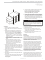
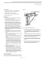
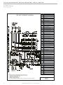
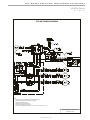
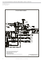
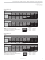
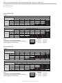
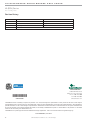
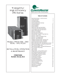
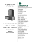
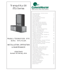
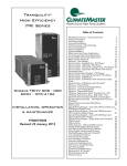
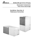
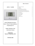
INSTALLATION INSTRUCTIONS
97B0042N05
Rev.: 15 May, 2015
ENERGY RECOVERY VENTILATOR
SERIES WB, WC, WD, WE, WF, & WG
Installation Instructions For Energy Recovery Wheel (Fixed)
For Stand Alone Over/Under Indoor Application
Energy recovery COMPONENT certified to the ARI Air-toAir Energy Recovery Ventilation Equipment Certification
Program in accordance with ARI Standard 1060-2000.
Actual performance in packaged equipment may vary.
Inspection
Upon receipt of shipment at the job site, carefully check the
shipment against the bill of lading. Make sure all units have
been received. Inspect the carton or crating housing of each
Rooftop Unit and inspect each unit for damage. Assure that
the carrier makes proper notation of any shortages or damage
on all copies of the freight bill and that he completes a Carrier
Inspection Report. Concealed damage not discovered during
unloading must be reported to the carrier within 15 days of
receipt of shipment. NOTE: It is the responsibility of the
purchaser to file all necessary claims with the carrier.
Storage
Upon the arrival of equipment at the job site, immediately store
units in a clean, dry area. Do not stack units. Do not remove
equipment from pallets until equipment is required for
installation.
Unit Protection
Cover rooftop units on the job site. Cap the open ends of pipes.
In areas where painting, plastering, roofing, or the spraying of
fireproof material has not been completed, all due precautions
must be taken to avoid physical damage to the units and
contamination by foreign material. Physical damage and
contamination may prevent proper start-up and may result
in costly equipment cleanup.
Application
Field supplied balancing dampers in duct are recommended.
Recovery Wheel Mode
The Recovery Wheel mode is accomplished by two blowers
providing continuous exhaust of stale indoor air and
replacement by equal amount of outdoor air. Energy recovery
is achieved by slowly rotating the energy recovery wheel within
the cassette frame work. In winter, the ERV adsorbs heat
and moisture from the exhaust air stream during one half of a
complete rotation and gives them back to the cold, drier intake
air supply during the other half rotation. In summer, the process
is automatically reversed. Heat and moisture are absorbed
from incoming fresh air supply and transferred to the exhaust
air stream. This process allows outdoor air ventilation rates
to be increased by factors of three or more without additional
energy penalty or increase in size of heating or air conditioning
systems.
ETL Certified per UL 1995 and CSA 22.2
Rigging Unit For Lifting
1. Maximum weight 300-1200 lbs. See Physical Data Table.
2. Remove crating.
3. All panels must be in place for rigging.
4. Remove barometric exhaust hood from door marked filter
access. Install barometric exhaust hood over exhaust blower
outlet.
5. Forklift channels must be removed from the base of
ERV.
6. Position unit and provide service access to ERV control
access door and wheel.
7. Duct work should be installed into roof curb before installing
ERV on curb.
8. Roof curb gasket must be applied to all top surfaces of the
curb.
9. Position unit on roof curb and provide service access to ERV
control access door and wheel.
CAUTION!
CAUTION! Danger of sharp metallic edges. Can cause
injury. Take care when servicing unit to avoid accidental
contact with sharp edges.
WARNING!
WARNING! Electric shock hazard. Can cause injury or death.
Before attempting to perform any service or maintenance,
turn the electrical power to unit OFF at disconnect switch(es).
Unit may have multiple power supplies.
WARNING!
WARNING! To avoid equipment damage, do not use these
units as a source of heat during the construction process.
The mechanical components and filters used in these units
will quickly become clogged with construction dirt and debris
which may cause system damage.
WARNING!
WARNING! The installation of water-source heat pumps and
all associated components, parts, and accessories which
make up the installation shall be in accordance with the
regulations of ALL authorities having jurisdiction and MUST
conform to all applicable codes. It is the responsibility of
the installing contractor to determine and comply with ALL
applicable codes, regulations and ANSI/NFPA No. 70
CLIMATEMASTER WATER-SOURCE HEAT PUMPS
W (ERV) Series
R e v. : 1 5 M a y, 2 0 1 5
This Page Intentionally Left Blank
2
C l i m a t e M a s t e r Wa t e r - S o u r c e H e a t P u m p s
THE SMART SOLUTION FOR ENERGY EFFICIENCY
W (ERV) Series
R e v. : 1 5 M a y, 2 0 1 5
8. Ground unit with a suitable ground connection either
through unit supply wiring or an earth ground.
NOTE: Unit voltage entries must be sealed
weather tight after wiring is complete.
9. Remove motor access panels. Locate belts fastened
to blower assembly. Install belt onto motor and blower
pulley. Adjust motor sheave to correct blower RPM for
CFM and external static pressure requirements. See
charts in this instruction. Multiple pulley arrangements
are available to meet the entire range.
CAUTION!
CAUTION! Blower speed must be adjusted for the given
external static pressure and airflow (CFM) requirements. If
blower speed is not adjusted for conditions, possible motor
over loading can occur.
Installation
1. Attach duct work to duct flanges on ERV.
2. Remove ERV control access panel to connect field
wiring.
3. Route class II low voltage wire (3 conductor) from
thermostat or energy management through small
bushing in end panel of ERV. See wiring diagram.
a. Thermostat (dependent) - connect in parallel at
rooftop unit with “G”, “C” and “W”. Then connect
matching color at terminal 1, 2, and 3 respectively
on ERV circuit board.
b. Energy Management - provide +24 VAC to “1” and
common, 24 VAC to “2’ terminals on ERV circuit
board.
c. Thermostat (dedicated) - splice into +24 vac
(blue wire) at (control circuit board) transformer
connection run wire to “R” terminal. Then run
another wire from “G” terminal to ERV (control
circuit board) terminal block #1.
4. All electrical connections must conform to any local
codes and current National Electric Codes (NEC) and
Canadian Electric Codes (CEC). Refer closely to unit
wiring diagram in unit and/or in these instructions for
proper wiring connections.
5. Refer to the unit nameplate for minimum circuit
ampacity (MCA) and maximum overcurrent protection
size (fuse).
6. Electrical data is listed on unit rating plate and motor
name plates.
7. Connect line voltage power supply to ERV fuse block
in control box of unit from disconnect switch. See
wiring diagram.
10. Replace access panel onto the ERV unit and secure.
11. Restore power to unit.
12. Cleanup once unit is operating properly, caulk
any open joints, holes or seams to make the units
completely air and water tight.
13. Leave this instruction manual with owner or in an
envelope to be kept near unit.
Operation
(How It Works)
The unit contains an Energy Recovery Wheel (ERW)
that is a new concept in rotary air-to-air heat exchangers.
Designed as a packaged unit for ease of installation and
maintenance, only the connection of electrical power is
required to make the system operational.
When slowly rotating through counter flowing exhaust
and fresh air streams the ERW adsorbs sensible heat
and latent heat from the warmer air stream and transfer
this total energy to the cooler air stream during the
second half of its rotating cycle. Rotating at 50-60
revolutions per minute, the wheel provides constant flow
of energy from warmer to cooler air stream. The large
energy transfer surface and laminar flow through the
wheel causes this constant flow of recovered energy
to represent up to 85% of the difference in total energy
contained within the two air streams.
Sensible and latent heat are the two components of total
heat. Sensible heat is energy contained in dry air and
latent heat is the energy contained within the moisture
of the air. The latent heat load from the outdoor fresh air
on an air conditioning system can often be two to three
c l i m a t e m a s t e r. c o m
3
CLIMATEMASTER WATER-SOURCE HEAT PUMPS
W (ERV) Series
R e v. : 1 5 M a y, 2 0 1 5
times that of the sensible heat load and in the winter it is
a significant part of a humidification heat load.
During both the summer and winter, the ERW transfers
moisture entirely in the vapor phase. This eliminates wet
surfaces that retain dust and promote fungal growth as
well as the need for a condensate pan and drain to carry
water.
Because it is constantly rotating when in the air stream,
the ERV is always being cleaned by air, first in one
direction then the other. Because it is always dry, dust or
other particles impinging on the surface during one half
cycle, are readily removed during the next half cycle.
During the heating season, when outdoor air
temperatures are below 15ºF, it is recommended to use
the (optional) low ambient kit (field installed).
Low Ambient Kit is appropriate for climates with limited
HVAC system operation when outdoor temperatures are
below 10ºF.
The frost threshold is the outdoor temperature at which
frost will begin to form on the ERV wheel. For Energy
Recovery Ventilators, the frost threshold is typically below
10ºF. Frost threshold is dependent on indoor temperature
and humidify. The table shows how the frost threshold
temperatures vary depending on indoor conditions.
FROST THRESHOLD TEMPERATURE
INDOOR RH AT 70ºF
FROST THRESHOLD
TEMPERATURE
20%
0ºF
30%
5ºF
40%
10ºF
Because Energy Recovery Ventilators have a low frost
threshold, frost control options are not necessary in many
climates. Where outdoor temperatures may drop below
the frost threshold during the ERV operational hours,
exhaust only frost control option is available.
Low Ambient Kit (Optional)
Low Ambient Kit turns off the supply blower when outdoor
temperatures fall below the frost threshold. The exhaust
only thermostat set points are field adjustable. Supply
fan operation is automatically restored when the exhaust
air temperature rises above the thermostat set point.
Provisions for introducing make-up air into the building
when the supply blower is off to avoid depressurization
should be considered.
4
Recovery Wheel Mode
On a thermostat call for blower operation in heating,
cooling or continuous blower, the ERW will rotate
between fresh air and exhaust air streams. Both the
fresh air and exhaust air blowers will also be operating to
overcome the air resistance of the ERV.
System Check
1. Disconnect main power.
2. Turn to “Cont” for blower operation on thermostat
controlled models.
3. Restore power to unit. Observe ERV wheel rotation
and both fresh air and exhaust air blowers will
operating.
NOTE: If Low ambient kit is used the jumper
between TB37-5 & TB37-6 should be removed.
Also if system check out is being conducted at
low ambient temperatures, technician should
be aware that this kit can cause system not to
operate.
4. Verify that the ERV (3) three phase blower motors
are phased sequentially ensuring correct rotation and
operation.
a. Disconnect power.
b. Reverse any two field power leads to the ERV.
c. Reapply power.
5. Verify that both blower motors are operating under
their full load AMP rating (FLA). The FLA can be
found on each motor and the unit nameplate.
A. Return Damper Settings
Manually adjust position of field installed dampers to
balance air flow.
B. Air Flow / Blower Speed Adjustment
Blower speed selection is accomplished by changing
the sheave setting on both fresh air and exhaust air
blowers. To set ERV for the required air flow (CFM),
the external static pressure applied to the ERV (duct
static) must be known. See the CFM vs External
Static Pressure chart for the appropriate unit to
determine the correct blower RPM for the specified
CFM and External Static Pressure.
After blower speed adjustments have been made. Ensure
that when the belt is replaced it is tensioned correctly.
The motor mounting plate can be adjusted to tension the
belt. If using a belt tension checker, adjust the span to the
appropriate setting and check the belt defection force.
The belt deflection force should be between 5-8 lbs or the
lowest tension at which the belt will not slip under peak
C l i m a t e M a s t e r Wa t e r - S o u r c e H e a t P u m p s
THE SMART SOLUTION FOR ENERGY EFFICIENCY
W (ERV) Series
R e v. : 1 5 M a y, 2 0 1 5
load conditions.
Figure 1
1. Disconnect main power to unit before making
adjustment to economizer and/or ERV unit.
SEGMENT RETAINER CATCH
SEGMENT RETAINER
2. Replace ERV control access cover.
WHEEL RIM
3. Set thermostat to normal operating position.
E
A
4. Restore power to unit.
Maintenance
1. All motors use pre-lubricated sealed bearings; no
further lubrication is necessary.
SEGMENT
2. Make visual inspection of motors, belts and wheel
rotating bearings during routine maintenance.
3. Eight pie-shaped segments, are seated on stops
between the segment retainer which pivots on the
wheel rim and secured to the hub and rim of wheel.
Annual inspection of the self cleaning wheel is
recommended. With power disconnected, remove
ERV access panels (rear) and unplug [J150 & P150]
(Refer to wiring diagram in this instruction
manual). Remove segment and wash with water and/
or mild detergent.
4. To install wheel segments follow steps A through
E . See Figure 1. Reverse procedure for segment
removal.
A. Unlock two segment retainers (one on each side of
the selected segment opening.
B. With the embedded stiffener facing the motor side,
insert the nose of the segment between the hub
plates.
C. Holding segment by the two outer corners, press
the segment towards the center of the wheel
and inwards against the spoke flanges. If hand
pressure does not fully seat the segment, insert
the flat tip of a screw driver between the wheel
rim and outer corners of the segment and apply
downward force while guiding the segment into
place.
D. Close and latch each segment retainer under
segment retaining catch.
E. Slowly rotate the wheel 180º. Install the second
segment opposite the first for counterbalance.
Rotate the two installed segments 90º to balance
the wheel while the third segment is installed.
Rotate the wheel 180º again to install the fourth
segment opposite the third. Repeat this sequence
with the remaining four segments.
D
C
D
B
SPOKE
HUB
static settings. To install a pulley kit.
1. Check content of pulley kit, if pulley kit contains:
a. An adjustable sheave and a fixed pitch pulley then
remove belt and both motor and blower pulley
b. An adjustable sheave then remove the motor
pulley.
c. A fixed pitch pulley then remove the blower pulley.
2. Replace pulley(s) with the pulley(s) from pulley kit.
Make sure each pulley is installed with a key. Tighten
the set screw on the pulley(s) to 100 in.lb.
3. Install the belt that came with the pulley kit. Tension
belt as explained in the blower speed adjustment
section.
4. Check the speed of the blower. Adjust the motor
sheave to increase or decrease the speed of the
blower. See blower adjustment section.
Pulley Kit Installation
The units are shipped from the factory at the low static
setting. Pulley kits are available for the medium and high
c l i m a t e m a s t e r. c o m
5
CLIMATEMASTER WATER-SOURCE HEAT PUMPS
W (ERV) Series
R e v. : 1 5 M a y, 2 0 1 5
W Series Stand Alone ERV’s for Over and Under Indoor Application
Features and Notes:
1. Stand alone design allows higher levels of outdoor air
to be introduced into the conditioned space.
2. Static test ports provided to verify intake and exhaust
CFM.
3. Balancing damper(s) is field provided when connected
to ductwork. System may not operate properly without
balancing damper.
4. See blower performance charts for airflow at various
E.S.P.
5. Filter rack with 2” pleated filters included.
FRESH AIR
TREATED AIR
EXHAUST AIR
RETURN AIR
ERV with Horizontal Ductwork
(balancing damper(s) field supplied)
A
F
K
D
D
G
J C
D
D
I
I
H
E
B
H
ERV Data
6
Dimensional Data
ERV Series
CFM Range
A
B
C
D
E
F
G
H
I
J
K
WB
300-1100
56.75
32.13
39.50
11.00
27.00
4.50
10.00
2.56
1.00
10.00
4.50
WC
1200-2000
54.38
37.25
37.50
12.00
30.00
8.00
4.00
3.63
1.50
7.00
5.00
WD
1200-2800
60.00
42.62
43.56
14.00
32.00
9.56
4.50
5.31
1.50
8.81
5.25
WE
2000-3600
60.00
46.69
57.37
16.50
39.50
12.13
6.38
3.59
5.88
11.75
6.75
WF
3000-4600
60.00
52.69
57.37
16.50
39.50
12.13
6.38
6.59
5.88
11.75
6.75
WG
4600-6200
72.00
70.88
63.63
19.50
39.50
12.13
6.50
15.69
5.88
12.00
6.75
C l i m a t e M a s t e r Wa t e r - S o u r c e H e a t P u m p s
THE SMART SOLUTION FOR ENERGY EFFICIENCY
W (ERV) Series
R e v. : 1 5 M a y, 2 0 1 5
ERV UNIT SCHEMATIC DIAGRAM
COMPONENT CODE
A131
Fixed Relay Board
B26
Motor, Exhaust Air
B27
Motor, Fresh Air
B28
Motor, Desiccant Wheel
B30
Motor, Damper (Optional)
C23
Capacitor, Wheel Motor
C25
Capacitor, Exhaust Air
C26
Capacitor, Fresh Air
DL43
Delay, Cycle Timer (Optional)
F29
Fuse
J33
Jack, Cycle Control (Optional)
J34
Jack, Cycle Control Harness (Optional)
J40
Jack, Cycle (Optional)
J48
Jack, Control Box (Fresh Air)
J50
Jack, Control Box (Wheel)
J51
Jack, Control Box (Exhaust Air)
J56
Jack, Control Box (Damper)
J148
Jack, Fresh Air Motor Harness
J150
Jack, Wheel Motor Harness
J151
Jack, Exhaust Air Motor Harness
J160
Jack, Damper Motor Harness
K94
Relay, On/O (Optional)
K163
Contactor , Exhaust Air Motor
K164
Contactor, Fresh Air Motor
P33
Plug, Cycle Control (Optional)
P34
Plug, Cycle Control Harness (Optional)
P40
Plug, Wheel Cycle (Optional)
P48
Plug, Fresh Air Motor Harness
P50
Plug, Wheel Motor Harness
P51
Plug, Exhaust Air Motor Harness
P56
Plug, Damper Motor Harness
P148
Plug, Fresh Air Motor
P150
Plug, Wheel Motor
P151
Plug, Exhaust Air Motor
P160
Plug, Damper Motor
S23
Thermostat - Low Ambient (Optional)
S26
Switch, Low Ambient (Optional)
S51
Switch, Door
S125
Switch, Ambient Override (Optional)
T27
T27 Transformer, Control
T28
T28 Transformer, Step-down (Optional)
BK
Black
BL
Blue
GR
Green
WIRE COLOR
(FIELD INSTALLED)
Wired in parallel at
thermostat connection.
Notes:
1. Remove jumper to install field optional low ambient switch.
2. Selective voltage terminals for proper unit voltage.
3. Optional low ambient switch.
4. Optional motorized intake damper.
5. Optional Stop, Start and Jog Control.
6. For energy management systems connect +24v to “G” and common 24v to “C”.
c l i m a t e m a s t e r. c o m
GY
Gray
OR
Orange
PK
Pink
RD
Red
WH
White
YL
Yellow
208/230-1-60
7
CLIMATEMASTER WATER-SOURCE HEAT PUMPS
W (ERV) Series
R e v. : 1 5 M a y, 2 0 1 5
ERV UNIT SCHEMATIC DIAGRAM
COMPONENT CODE
A131
Fixed Relay Board
B26
Motor, Exhaust Air
B27
Motor, Fresh Air
B28
Motor, Desiccant Wheel
B30
Motor, Damper (Optional)
C23
Capacitor, Wheel Motor
DL43
Delay, Cycle Timer (Optional)
F29
Fuse
J33
Jack, Cycle Control (Optional)
J34
Jack, Cycle Control Harness (Optional)
J40
Jack, Cycle (Optional)
J48
Jack, Control Box (Fresh Air)
J50
Jack, Control Box (Wheel)
J51
Jack, Control Box (Exhaust Air)
J56
Jack, Control Box (Damper)
J148
Jack, Fresh Air Motor Harness
J150
Jack, Wheel Motor Harness
J151
Jack, Exhaust Air Motor Harness
J152
Jack, Transformer (High Voltage)
J160
Jack, Damper Motor Harness
K94
Relay, On/Off (Optional)
K163
Contactor, Exhaust Air Motor
K164
Contactor, Fresh Air Motor
P33
Plug, Cycle Control (Optional)
P34
Plug, Cycle Control Harness (Optional)
P40
Plug, Wheel Cycle (Optional)
P48
Plug, Fresh Air Motor Harness
P50
Plug, Wheel Motor Harness
P51
Plug, Exhaust Air Motor Harness
P56
Plug, Damper Motor Harness
P148
Plug, Fresh Air Motor
P150
Plug, Wheel Motor
P151
Plug, Exhaust Air Motor
P152
Plug, Transformer (High Voltage)
P160
Plug, Damper Motor
S23
Thermostat - Low Ambient (Optional)
S26
Switch, Low Ambient (Optional)
S51
Switch, Door
S125
Switch, Ambient Override (Optional)
T27
Trans former, Control
T28
Trans former, Step-down (Optional)
BK
Black
BL
Blue
GR
Green
WIRE COLOR
(FIELD INSTALLED)
Wired in parallel at
Thermostat connection.
Notes:
1. Remove jumper to install field optional low ambient switch.
2. Step-down transformer assembly for 460/575 volt only units.
3. Move wire for different voltage input.
4. Optional low ambient switch.
5. Optional motorized intake damper.
6. For energy management systems connect +24v to green and common 24v to black.
8
C l i m a t e M a s t e r Wa t e r - S o u r c e H e a t P u m p s
GY
Gray
OR
Orange
PK
Pink
RD
Red
WH
White
YL
Yellow
208/230-3-60
460-3-60
575-3-60
THE SMART SOLUTION FOR ENERGY EFFICIENCY
W (ERV) Series
R e v. : 1 5 M a y, 2 0 1 5
ERV UNIT WIRING DIAGRAM
Notes:
1. Remove jumper to install field optional low ambient switch.
2. Selective voltage terminals for proper unit voltage.
3. Optional low ambient switch.
4. Optional motorized intake damper.
5. Optional Stop, Start and Jog Control.
6. For energy management systems connect +24v to “G” and common 24v to “C”.
Desiccant Wheel for Roof top Unit
208-230V (1 PH)
c l i m a t e m a s t e r. c o m
9
CLIMATEMASTER WATER-SOURCE HEAT PUMPS
W (ERV) Series
R e v. : 1 5 M a y, 2 0 1 5
ERV UNIT WIRING DIAGRAM
Notes:
1. Remove jumper to install field optional low ambient switch.
2. Step-down transformer assembly for 460/575 volt units.
3. Selective voltage terminals for proper unit volt age.
4. Optional low ambient switch.
5. Optional motorized intake damper.
6. Optional Stop, Start and Jog Control.
7. For energy management systems connect +24v to “G” and common 24v to “C”.
10
C l i m a t e M a s t e r Wa t e r - S o u r c e H e a t P u m p s
Desiccant Wheel for Roof top Unit
208-230/460/575V (3 PH)
THE SMART SOLUTION FOR ENERGY EFFICIENCY
W (ERV) Series
R e v. : 1 5 M a y, 2 0 1 5
Blower RPM for WB
SUPPLY
Mist Eliminator Filter in Intake Hood (1.5HP)
External Static Pressure (in water)
300
CFM
0
0.25
0.5
0.75
1
1.25
1.5
N/A
N/A
980
1065
1320
1400
1520
1595
500
N/A
905
1050
1215
1360
1495
700
865
1035
1210
1330
1440
1535
1620
900
1030
1205
1325
1435
1530
1615
1725
1100
1200
1320
1430
1525
1605
1720
1800
EXHAUST
Barometric Hood, 2" Pleated Filters (1.5HP)
External Static Pressure (in water)
300
CFM
0
0.25
0.5
0.75
1
1.25
1.5
N/A
815
1030
1185
1305
1450
1535
1610
500
N/A
950
1075
1220
1375
1490
700
810
1070
1195
1295
1445
1510
1645
900
995
1125
1290
1405
1500
1600
1690
1100
1120
1280
1400
1495
1595
1685
1770
RPM Range
Notes:
1. Drive losses included in the above tables.
2. Performance can vary depending on ambient conditions
3. Blower RPMs are for reference only
Low
1000-1300
Standard Unit
Medium 1300-1750
Optional Kit
High
Optional Kit
1750-2200
Blower RPM for WC
SUPPLY
Mist Eliminator Filter in Intake Hood (2HP)
External Static Pressure (in water)
CFM
0
0.25
0.5
0.75
1
1.25
1.5
1200
990
1075
1220
1380
1480
1605
1720
1400
1030
1165
1280
1410
1520
1620
1740
1600
1135
1250
1340
1445
1570
1665
1760
1800
1240
1330
1425
1550
1625
1720
1785
2000
1295
1405
1540
1615
1705
1760
1830
EXHAUST
Barometric Hood, 2" Pleated Filters (2HP)
External Static Pressure (in water)
CFM
0
0.25
0.5
0.75
1
1.25
1.5
1200
900
1085
1235
1380
1495
1585
1680
1400
1050
1220
1345
1490
1535
1630
1715
1600
1205
1335
1430
1520
1625
1705
1790
1800
1315
1425
1510
1580
1655
1775
1850
2000
1390
1490
1570
1650
1735
1750
N/A
Notes:
1. Drive losses included in the above tables.
2. Performance can vary depending on ambient conditions
3. Blower RPMs are for reference only
c l i m a t e m a s t e r. c o m
RPM Range
Low
1000-1300
Standard Unit
Medium 1300-1700
Optional Kit
High
Optional Kit
1700-2080
11
CLIMATEMASTER WATER-SOURCE HEAT PUMPS
W (ERV) Series
R e v. : 1 5 M a y, 2 0 1 5
Blower RPM for WD
SUPPLY
Mist Eliminator Filter in Intake Hood (3HP)
External Static Pressure (in water)
0
0.25
0.5
0.75
1
1.25
1.5
N/A
900
1045
1135
1255
1395
1410
1600
880
1035
1130
1245
1385
1405
1450
2000
1045
1145
1235
1325
1400
1440
1555
2400
1135
1300
1375
1435
1505
1550
1590
2800
1295
1365
1435
1515
1580
1625
1695
1200
CFM
EXHAUST
Barometric Hood, 2" Pleated Filters (3HP)
External Static Pressure (in water)
0
0.25
0.5
0.75
1
1.25
1.5
N/A
955
1075
1185
1285
1355
1495
1600
945
1055
1175
1265
1335
1445
1635
2000
1045
1170
1330
1395
1440
1570
1695
2400
1210
1325
1435
1510
1580
1620
1675
2800
1315
1475
1500
1595
1710
1755
1790
1200
CFM
RPM Range
Notes:
1. Drive losses included in the above tables.
2. Performance can vary depending on ambient conditions
3. Blower RPMs are for reference only
Low
950-1320
Standard Unit
Medium 1325-1565
Optional Kit
High
Optional Kit
1570-1880
Blower RPM for WE
SUPPLY
Mist Eliminator Filter in Intake Hood (3HP)
External Static Pressure (in water)
CFM
0
0.25
0.5
0.75
1
1.25
1.5
2000
735
860
920
1005
1075
1150
1220
2400
850
945
1030
1090
1110
1215
1265
2800
935
1020
1080
1145
1200
1255
1335
3200
1015
1075
1105
1195
1285
1325
1380
3600
1065
1125
1220
1305
N/A
N/A
N/A
EXHAUST
Barometric Hood, 2" Pleated Filters (3HP)
External Static Pressure (in water)
CFM
0
0.25
0.5
0.75
1
1.25
1.5
2000
740
855
930
970
1080
1155
1240
2400
800
925
1015
1075
1145
1225
1280
2800
885
1010
1070
1140
1235
1255
1330
3200
950
1065
1135
1230
1290
1325
N/A
3600
1055
1130
1235
1280
1310
N/A
N/A
Notes:
1. Drive losses included in the above tables.
2. Performance can vary depending on ambient conditions
3. Blower RPMs are for reference only
12
RPM Range
Low
700-1025
Standard Unit
Medium 1030-1305
Optional Kit
High
Optional Kit
1325-1575
C l i m a t e M a s t e r Wa t e r - S o u r c e H e a t P u m p s
THE SMART SOLUTION FOR ENERGY EFFICIENCY
W (ERV) Series
R e v. : 1 5 M a y, 2 0 1 5
Blower RPM for WF
SUPPLY
Mist Eliminator Filter in Intake Hood (5HP)
External Static Pressure (in water)
0
0.25
0.5
0.75
1
1.25
1.5
840
990
1065
1135
1215
1265
1335
3400
875
1060
1130
1205
1255
1320
1385
3800
1015
1120
1200
1245
1315
1365
1450
4200
1080
1195
1240
1350
1395
1445
1510
4600
1120
1200
1315
1380
1460
1515
1560
3000
CFM
EXHAUST
Barometric Hood, 2" Pleated Filters (5HP)
External Static Pressure (in water)
0
0.25
0.5
0.75
1
1.25
1.5
850
995
1065
1135
1220
1270
1335
3400
925
1060
1130
1225
1265
1330
1375
3800
1020
1120
1220
1285
1325
1370
1430
4200
1100
1215
1280
1345
1400
1435
1480
4600
1150
1275
1340
1415
1475
1520
1565
3000
CFM
RPM Range
Notes:
1. Drive losses included in the above tables.
2. Performance can vary depending on ambient conditions
3. Blower RPMs are for reference only
Low
780-1020
Standard Unit
Medium 1000-1315
Optional Kit
High
Optional Kit
1315-1700
Blower RPM for WG
SUPPLY
Mist Eliminator Filter in Intake Hood (5HP)
External Static Pressure (in water)
CFM
0
0.25
0.5
0.75
1
1.25
1.5
4600
795
900
960
1010
1090
1135
1165
5000
835
945
1000
1060
1135
1155
1230
5400
895
985
1040
1130
1155
1220
1265
5800
940
1025
1085
1145
1225
1250
1300
6200
990
1070
1105
1210
1245
1290
N/A
EXHAUST
Barometric Hood, 2" Pleated Filters (5HP)
External Static Pressure (in water)
CFM
0
0.25
0.5
0.75
1
1.25
1.5
4600
780
910
900
1045
1085
1135
1185
5000
825
945
1015
1075
1125
1180
1230
5400
890
990
1065
1105
1170
1220
1270
5800
940
1025
1085
1165
1215
1250
1310
6200
980
1060
1150
1205
1235
1305
N/A
Notes:
1. Drive losses included in the above tables.
2. Performance can vary depending on ambient conditions
3. Blower RPMs are for reference only
c l i m a t e m a s t e r. c o m
RPM Range
Low
700-900
Standard Unit
Medium 900-1100
Optional Kit
High
Optional Kit
1100-1300
13
14
C l i m a t e M a s t e r Wa t e r - S o u r c e H e a t P u m p s
Rev.: 11/09
Please refer to the CM Installation, Operation and Maintenance Manual for operating and maintenance instructions.
LC083
*LC083*
NOTE: Some states or Canadian provinces do not allow limitations on how long an implied warranty lasts, or the limitation or exclusions of consequential or incidental damages, so the foregoing exclusions and limitations may
not apply to you. This warranty gives you specific legal rights, and you may also have other rights which vary from state to state and from Canadian province to Canadian province.
Climate Master, Inc. • Customer Service • 7300 S.W. 44th Street • Oklahoma City, Oklahoma 73179 (405) 745-6000
OBTAINING WARRANTY PERFORMANCE
Normally, the contractor or service organization who installed the products will provide warranty performance for the owner. Should the installer be unavailable, contact any CM recognized dealer, contractor or service organization. If assistance is required in obtaining warranty performance, write or call:
LIMITATION OF LIABILITY
CM shall have no liability for any damages if CM’s performance is delayed for any reason or is prevented to any extent by any event such as, but not limited to: any war, civil unrest, government restrictions or restraints, strikes
or work stoppages, fire, flood, accident, shortages of transportation, fuel, material, or labor, acts of God or any other reason beyond the sole control of CM. CM EXPRESSLY DISCLAIMS AND EXCLUDES ANY LIABILITY FOR CONSEQUENTIAL OR INCIDENTAL DAMAGE IN CONTRACT, FOR BREACH OF ANY EXPRESS OR IMPLIED WARRANTY, OR IN TORT, WHETHER FOR CM’s NEGLIGENCE OR AS
STRICT LIABILITY.
LIMITATION OF REMEDIES
In the event of a breach of the Limited Express Warranty, CM will only be obligated at CM’s option to repair the failed part or unit or to furnish a new or rebuilt part or unit in exchange for the part or unit which has failed. If
after written notice to CM’s factory in Oklahoma City, Oklahoma of each defect, malfunction or other failure and a reasonable number of attempts by CM to correct the defect, malfunction or other failure and the remedy fails
of its essential purpose, CM shall refund the purchase price paid to CM in exchange for the return of the sold good(s). Said refund shall be the maximum liability of CM. THIS REMEDY IS THE SOLE AND EXCLUSIVE
REMEDY OF THE BUYER OR THEIR PURCHASER AGAINST CM FOR BREACH OF CONTRACT, FOR THE BREACH OF ANY WARRANTY OR FOR CM’S NEGLIGENCE OR IN STRICT LIABILITY.
Limitation: This Limited Express Warranty is given in lieu of all other warranties. If, notwithstanding the disclaimers contained herein, it is determined that other warranties exist, any such warranties, including without limitation any express warranties or any implied warranties of fitness for particular purpose and merchantability, shall be limited to the duration of the Limited Express Warranty.
CM is not responsible for: (1) The costs of any fluids, refrigerant or other system components, or associated labor to repair or replace the same, which is incurred as a result of a defective part covered by CM’s Limited Express
Warranty; (2) The costs of labor, refrigerant, materials or service incurred in removal of the defective part, or in obtaining and replacing the new or repaired part; or, (3) Transportation costs of the defective part from the installation site to CM or of the return of any part not covered by CM’s Limited Express Warranty.
This warranty does not cover and does not apply to: (1) Air filters, fuses, refrigerant, fluids, oil; (2) Products relocated after initial installation; (3) Any portion or component of any system that is not supplied by CM, regardless
of the cause of the failure of such portion or component; (4) Products on which the unit identification tags or labels have been removed or defaced; (5) Products on which payment to CM is or has been in default; (6) Products
which have defects or damage which result from improper installation, wiring, electrical imbalance characteristics or maintenance; or are caused by accident, misuse or abuse, fire, flood, alteration or misapplication of the product; (7) Products which have defects or damage which result from a contaminated or corrosive air or liquid supply, operation at abnormal temperatures, or unauthorized opening of refrigerant circuit; (8) Mold, fungus or bacteria
damages; (9) Products subjected to corrosion or abrasion; (10) Products manufactured or supplied by others; (11) Products which have been subjected to misuse, negligence or accidents; (12) Products which have been operated
in a manner contrary to CM’s printed instructions; or (13) Products which have defects, damage or insufficient performance as a result of insufficient or incorrect system design or the improper application of CM’s products.
GRANT OF LIMITED EXPRESS WARRANTY
CM warrants CM products purchased and retained in the United States of America and Canada to be free from defects in material and workmanship under normal use and maintenance as follows: (1) All complete air conditioning, heating and/or heat pump units built or sold by CM for twelve (12) months from date of unit start up or eighteen (18) months from date of shipment (from factory), whichever comes first; (2) Repair and replacement parts,
which are not supplied under warranty, for nintey (90) days from date of shipment (from factory). All parts must be returned to CM’s factory in Oklahoma City, Oklahoma, freight prepaid, no later than sixty (60) days after
the date of the failure of the part; if CM determines the part to be defective and within CM’s Limited Express Warranty, CM shall, when such part has been either replaced or repaired, return such to a factory recognized dealer,
contractor or service organization, F.O.B. CM’s factory, Oklahoma City, Oklahoma, freight prepaid. The warranty on any parts repaired or replaced under warranty expires at the end of the original warranty period.
EXCEPT AS SPECIFICALLY SET FORTH HEREIN, THERE IS NO EXPRESS WARRANTY AS TO ANY OF CM’S PRODUCTS. CM MAKES NO WARRANTY AGAINST LATENT DEFECTS. CM MAKES
NO WARRANTY OF MERCHANTABILITY OF THE GOODS OR OF THE FITNESS OF THE GOODS FOR ANY PARTICULAR PURPOSE.
It is expressly understood that unless a statement is specifically identified as a warranty, statements made by Climate Master, Inc., a Delaware corporation, (“CM”) or its representatives, relating to CM’s products, whether oral,
written or contained in any sales literature, catalog or any other agreement, are not express warranties and do not form a part of the basis of the bargain, but are merely CM’s opinion or commendation of CM’s products.
CLIMATE MASTER, INC.
LIMITED EXPRESS WARRANTY/ LIMITATION OF REMEDIES AND LIABILITY
CLIMATEMASTER WATER-SOURCE HEAT PUMPS
W (ERV) Series
R e v. : 1 5 M a y, 2 0 1 5
THE SMART SOLUTION FOR ENERGY EFFICIENCY
W (ERV) Series
R e v. : 1 5 M a y, 2 0 1 5
Notes
c l i m a t e m a s t e r. c o m
15
CLIMATEMASTER WATER-SOURCE HEAT PUMPS
W (ERV) Series
R e v. : 1 5 M a y, 2 0 1 5
Revision History
Item:
Action:
05/15/15
Date:
All
Changed Series U to W
05/01/15
All
Changed Series N to U
04/04/14
Logos - page 1 & 16
Updated
11/21/13
Created
7300 S.W. 44th Street
Oklahoma City, OK 73179
Phone: 405-745-6000
Fax: 405-745-6058
climatemaster.com
*97B0042N05*
97B0042N05
ClimateMaster works continually to improve its products. As a result, the design and specifications of each product at the time of order may be
changed without notice and may not be as described herein. Please contact ClimateMaster’s Customer Service Department at 1-405-745-6000 for
specific information on the current design and specifications. Statements and other information contained herein are not express warranties and
do not form the basis of any bargain between the parties, but are merely ClimateMaster’s opinion or commendation of its products. For the latest
version of this document go to climatemaster.com.
ClimateMaster is a proud supporter of the Geothermal Exchange Organization - GEO. For more information visit geoexchange.org.
© ClimateMaster, Inc. 2013
16
C l i m a t e M a s t e r Wa t e r - S o u r c e H e a t P u m p s