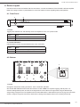
1
Installation Manual
EA-AMP-12D-45A
45 Watt, Class D
12 Channel Amplifier
EA-AMP-12D-45A Installation Manual
Important Safety Instructions
Warning: To reduce the risk of fire or electric shock, do not expose this apparatus to rain or moisture.
1. Read these instructions.
2. Keep these instructions.
3. Heed all warnings.
4. Follow all instructions.
5. Do not use this apparatus near water.
6. Clean only with dry cloth.
7. Do not block any ventilation openings. Install in accordance with the manufacturer’s instructions.
8. Do not install near any heat sources such as radiators, heat registers, stoves, or other apparatus (including
amplifiers) that produce heat.
9. Do not defeat the safety purpose of the polarized or grounding-type plug. A polarized plug has two blades with one
wider than the other. A grounding type plug has two blades and a third grounding prong. The wide blade or the
third prong are provided for your safety. If the provided plug does not fit into your outlet, consult an electrician for
replacement of the obsolete outlet.
10. Protect the power cord from being walked on or pinched particularly at plugs, convenience receptacles, and the
point where they exit from the apparatus.
11. Only use attachments/accessories specified by the manufacturer.
12. Use only with the cart, stand, tripod, bracket, or table specified by the manufacturer, or sold with the apparatus.
When a cart is used, use caution when moving the cart/apparatus combination to avoid injury from tip-over.
13. Unplug this apparatus during lightning storms or when unused for long periods of time.
14. Refer all servicing to qualified service personnel. Servicing is required when the apparatus has been damaged
in any way, such as power-supply cord or plug is damaged, liquid has been spilled or objects have fallen into the
apparatus, the apparatus has been exposed to rain or moisture, does not operate normally, or has been dropped.
15. The MAINS plug or an appliance coupler is used as the disconnect device, so the disconnect device shall remain
readily operable.
16. This apparatus has been designed with Class-I construction and must be connected to a mains socket outlet with
a protective earthing connection (the third grounding prong).
CAUTION
CAUTION: TO REDUCE THE RISK OF
ELECTRICAL SHOCK.
DO NOT REMOVE COVER. NO USER
SERVICEABLE PARTS INSIDE.
REFER SERVICING TO QUALIFIED
SERVICE PERSONNEL.
The lightning flash with arrowhead symbol, within an equilateral
triangle, is intended to alert the user to the presence of uninsulated dangerous voltage within the product’s enclosure that
may be of sufficient magnitude to constitute a risk of electric
shock to persons.
The exclamation point within an equilateral triangle is intended
to alert the user to the presence of important operating
and maintenance (servicing) instructions in the literature
accompanying the appliance.
Pg. 3
www.snapav.com Support: 866.838.5052
EA-AMP-12D-45A Installation Manual
Table of Contents
1. Features
5
2. Package Contents
6
3. Recommended For Installation
6
3.1. Tools
6
3.2. Materials
6
3.3. Speaker Recommendation
6
4. Device Layout
7
4.1. Front Panel
7
4.2. Bottom
7
4.3. Rear Panel
8
5. System Design Considerations
9
5.1. Speaker Placement
9
5.2. Volume Control
9
5.2.1. No Inline Volume Controls
9
5.2.2. With Inline Volume Controls
9
5.3. Control Method
9
6. Installation and Setup
10
10
6.1. Positioning the Amplifier
6.1.1. Rack Mounting
6.2. Speaker Connections and Setup
10
11
6.2.1. Terminating Speaker Wire Connectors
11
6.2.2. Normal (Stereo) Output Zone
11
6.2.3. Bridged Output Zone
11
6.3. Source Connections and Input Setup
12
6.3.1. Input Selector Switch
12
6.3.2. Normal Stereo Input (4/8Ω Output)
12
6.3.3. Bridged Stereo Input (8Ω Only Output)
12
6.3.4. Normal Mono Input (4/8Ω Output)
12
6.3.5. Bridged Mono Input (8Ω Only Output)
12
6.4. Amplifier Power Control
13
6.4.1. Master Power Switch
13
6.4.2. Front Panel Power Button
13
6.4.3. Power ON Mode
13
6.4.4. 12 Volt Trigger
13
6.4.5. AUTO (Audio Sense)
13
6.5. Zone Volume Calibration
6.5.1. Calibration Setup Tips
14
14
Applications Overview
15
6.6. Multi-Room Audio with Dedicated Sources
15
6.7. Multi-source Multi-Room Audio
16
7. Specifications
17
8. Troubleshooting
17
9. Warranty
18
10. Contacting Technical Support
18
Pg. 4
© 2013 Episode®
EA-AMP-12D-45A Installation Manual
Welcome to Episode
Episode® is one of the most highly-regarded brands of audio products available today. We appreciate your
business, and we stand committed to providing our customers with the highest degree of quality and service in the
industry.
Episode amplifiers are built on the latest digital technology and deliver efficient, clean power to every room.
Each model is designed to produce the subtle details of music, while having the flexibility to meet a variety of
installations. For the best sound quality, use Episode speakers to complete the system.
1. Features
Durable Audiophile Design
These Episode Amplifiers use the latest digital technology to deliver cool-running performance from a compact,
reliable package. Plus, they feature superior-quality components for outstanding sound quality, and are up to 90%
more efficient than conventional analog designs.
Multiple Stages of Protection
Each pair of channels (or Zone) is individually protected with an operation mode indicated by bi-color LEDs on
the front of the amplifier. These enable simple troubleshooting. If the circuitry determines that a channel must be
shut down for protection due to a short, only the channels that are effected will be turned off. The other zones will
continue to play.
Global (A & B) and Direct Inputs
A dedicated input can be assigned to a pair of channels via the channel Line In connection. Each pair of channels
can also be configured to play common signals from the Global Input. A 3-position switch is available for each
channel pair to choose between the Line-In and the 2 Global-Inputs. This provides unparalleled flexibility that is
needed for today’s demanding custom audio installations.
Individual Channel and Gain Adjustments
Each pair of channels has its own level adjustment which adjusts the maximum output. This allows the output to
be perfectly matched to its area. It can also be used to provide a limit on how loud each speaker may be allowed to
play.
Installation-Friendly Connections
Each pair of speakers features a removable speaker wire connector that accommodates 14-18 gauge stranded
speaker wire. The power cord is removable as well, facilitating fast and simple installations. The Global Inputs,
and individual Channel Inputs are all high-quality RCA connectors.
Bridging
The power output of adjacent channels can be combined to provide extra power when needed in certain areas.
This is easily accomplished by flipping a single switch. (Maintain an 8 ohm minimum when using bridge mode.)
Rack-Mountable
Each Episode amplifier includes an accessory package of rack ‘ears’ that may be attached to the amplifier. The
amplifier feet can be easily removed for clean rack mounting.
Power Mode
Power state can be toggled using the front Power Button, 12V input, or Audio Sensing for easy automated or
manual control.
Note: The front panel power button is inoperative when the 12V Trigger or Audio Sense power modes are
selected.
Pg. 5
www.snapav.com Support: 866.838.5052
EA-AMP-12D-45A Installation Manual
2. Package Contents
(1)
(1)
(2)
(4)
(1)
EA-AMP-12D-45A
Installation Manual
Rack Mounting Ears and Screws
Removable Rack Feet and Screws
Detachable IEC Power Cable
3. Recommended For Installation
3.1. Tools
• #2 Philips Screwdriver
• Wire Strippers
3.2. Materials
• Speaker Wire
Use high-quality, 2 or 4 conductor, 14-18 gauge (AWG) speaker wire. The higher the strand count, the
better the sound quality will be. Using 4 conductor cables for stereo zones can save money and time on the
installation by reducing the number of wires that must be pulled.
• Source Input Cables
Source inputs on the EA-AMP-12D-45A utilize RCA connections. Use high-quality pre- or field-terminated RCA
cables.
• Speaker Selectors and Volume Controls
For multi-room audio applications, there may be volume controls or zone selectors between the amplifier
speaker output and the speakers. Make sure that any equipment used is capable of handling the wattage
supplied by the amplifier.
Any equipment used to add more speakers must have built–in impedance matching, or the speaker wiring must
be configured to provide the correct impedance at the amplifier.
3.3. Speaker Recommendation
The EA-AMP-12D-45A is capable of handling a 4 ohm load at 45 watts for normal outputs, or an 8 ohm load at 90
watts for bridged outputs. Use speakers rated for 4-8 ohms and capable handling at least 45 watts RMS for the
best performance.
Avoid attaching more than two 8 ohm speakers or one 4-6 ohm speaker directly to any single output zone in
Normal mode. Attach only 8 ohm speakers directly to bridged output zones. When attaching multiple speakers
to an output, use an impedance matching volume control or selector between the amplifier and the speakers if
necessary to maintain the correct impedance.
Pg. 6
© 2013 Episode®
EA-AMP-12D-45A Installation Manual
4. Device Layout
Use this section to become familiar with the connections, controls and features of the EA-AMP-12D-45A amplifier.
Refer to the page numbers in parentheses for more information on items regarding setup and operation.
4.1. Front Panel
1
2
1. Power
Toggle power between On and Standby when the amplifier is in the “On” power mode.
Color
State
Blue
Power On, Normal Operation
Red
Standby
2. Channel Indicators
Indicates status of each channel based on the color of the LED.
Color
State
Blue
Channel is functioning correctly.
Red
Channel is in Protection Mode
4.2. Bottom
1
1. Power
Change the transformer setting to allow for 115V or 230V AC operation.
ote: The EA-AMP-12D-45A includes an IEC cable meant for use with a NEMA 5-15 receptacle supplying 115V AC power.
N
For
countries utilizing 230V AC power, the cable can be swapped to the correct cable for that region. When using the 230V AC input
voltage setting, change the fuse in the amplifier from the included T8AL 250V to a T4AL 250V fuse (See item 12, page 8 for fuse holder
location). Using the wrong fuse could result in blown fuses or damage to the amplifier, which is not covered by the warranty.
Pg. 7
www.snapav.com Support: 866.838.5052
EA-AMP-12D-45A Installation Manual
4.3. Rear Panel
3
1
2
4
5
6
7
Same for All Outputs
8
9 10
11
12
1. Global Input A
RCA stereo line for source A input.
2. Global Input B
RCA stereo line for source B input.
3. Level (Gain/Volume)
Adjust the gain level of each output zone individually. (Counterclockwise for minimum; clockwise for
maximum.)
4. Channel Input Selector
Select the Global Input (A or B) or the local Line In for the output.
5. Bridge Switch
Select whether a pair of left and right output channels are individual or bridged together for a more powerful
mono channel. The NORMAL setting yields (2) 4Ω stable channels in one zone (Left and right stereo, 45w per
channel). The BRIDGED setting yields (1) 8Ω stable channel in one zone (mono 90w channel).
6. Local Line In
Local input for zone (plays only on that zone’s outputs). Use for instances where the zone will always play a
different source than other zones. Set the Channel Input Selector switch to “Line In” to use this input.
7. Speaker Output
Set-screw connector to attach speaker wires to zone output. Note the diagram below the connector port on the
chassis of the amplifier indicating proper speaker wire connections for stereo or bridged output.
8. Power Mode Selector
Set the preferred power mode: ON, AUTO or TRIGGER DC 12V.
9. Master Power Switch
Rocker style toggle switch for master power control.
10.12 Volt Trigger Ports (In and Out)
Allows the amplifier to be controlled via 12V DC trigger when amp is set to TRIGGER DC 12V. When 4.5-15
Volts DC are applied, amplifier will turn on. When voltage is dropped, amplifier turns back off.
11.Power Connector
Connect the included grounded, 3 prong IEC power cord for use with 120V AC applications, or the correct
power cord type for the country for 230V AC applications.
12.Fuse Holder
User-serviceable fuse holder. 1 spare fuse is included inside the holder. Replacement fuse types are listed in
Specifications on page17.
Pg. 8
© 2013 Episode®
EA-AMP-12D-45A Installation Manual
5. System Design Considerations
5.1. Speaker Placement
The EA-AMP-12D-45A amplifier output zones are arranged in pairs of left and right channels. Each pair can be
bridged for one mono channel. For most applications, a pair of stereo speakers properly placed in a room (or a
single dual voice coil speaker playing stereo audio) will sound better than a mono bridged output feeding one
bigger speaker unless the extra power is needed for a high wattage speaker or a long wire run.
When planning speaker locations, check with the speaker manufacturer for the best possible layout for the
models used. As a general guideline, try to spread locations evenly to accommodate both the room dimensions
and the overall balance of each channel (left and right). Consider using a bridged output for large outdoor
speakers, or if a non-powered subwoofer will be attached to an output. Full information on speaker wiring and
connections can be found in Section 6.2 Speaker Connections and Setup.
5.2. Volume Control
For fine-tuning output zone volume levels after installation, see Section 6.5 Zone Volume Calibration.
5.2.1.No Inline Volume Controls
When setting up a system without inline volume controls, make sure that the source used has adjustable volume for
the output connected to the amplifier. The system volume will be controlled by setting the level of the source output.
Any zones playing that input will change volume together. Each zone level can be calibrated individually to a degree
by changing its LEVEL knob.
This setup is optimal for zones utilizing dedicated input sources, as the volume is usually much more adjustable than
if an inline volume control were being used, and other zones aren’t affected by source volume changes.
5.2.2.With Inline Volume Controls
In systems where each output zone is wired with an inline volume control between the amplifier and the speakers,
volume can be adjusted in each zone individually no matter what the other zones are set to. Source volume and
zone levels are typically fine-tuned during setup, and the end user adjusts each zone at the volume control during
normal use.
If a multi-source setup is used (as in Section 6.7 Multi-source Multi-Room Audio) there will be full control of both
source selection and volume in every zone. Combined with an automation system for remote control of sources, this
setup allows for the most control possible in a multi-room audio application using the EA-AMP-12D-45A.
5.3. Control Method
When deciding on the control method for the amplifier, consider the sources in use and the purpose of the amplifier
on the job. See Section 6.4 Amplifier Power Control for full instructions on power control setup and operation.
•Using the front Power button (Power ON mode) will allow manual control at all times, and is useful for
installations where the audio system will be powered on and shut down regularly at the equipment. Use this
mode if the system is always set by the user at the equipment.
•Avoid using Power ON mode for jobs where a remote is typically used to control the system, since the
amplifier would be required to be on at all times. The amplifier could be set to Stand-by inadvertently which
may confuse the user into thinking there is a problem.
•When the system will be controlled from anywhere but at the equipment, try to use the TRIGGER DC 12V
or AUTO mode for amplifier power control. These options are the most reliable since the amplifier will be
automated to turn on whenever it is needed.
•When using a source that remains on at all times, using the AUTO mode for amplifier control could keep the
unit powered at all times due to either signal or noise on the line from the source. This can be avoided by
turning the source off completely when not in use, or by using a 12 volt trigger instead.
Pg. 9
www.snapav.com Support: 866.838.5052
EA-AMP-12D-45A Installation Manual
6. Installation and Setup
6.1. Positioning the Amplifier
Episode amplifiers are designed to help deliver a great audio experience that makes your music come alive
for years to come. However, where you place the amplifier can have a large effect on the performance you
receive and the life of the unit.
• Be sure that the unit is in a well-ventilated area that provides adequate cooling.
• Do not block the cooling vents located on both sides of the unit.
• Do not place the unit on carpeting or any similar material.
• Do not install the unit near a source of heat, or in an extremely humid or wet location.
•If the installation lacks good air flow (such as solid cabinet doors or wall-mounted racks), it may be
necessary to create ventilation to allow outside air into the space.
• Allow a minimum of 5” of free air space above the unit.
• Allow a minimum of 3” of free air space on either side of the unit. (Does not apply to rack mounting)
Minimum of 3"
free air space on
each side.
5in.
Minimum of 5"
free air space
above.
3in.
3in.
2in.
6.1.1.Rack Mounting
The EA-AMP-12D-45A includes hardware to rack-mount the amplifier. To prepare the amplifier, attach the
rack ears at the front left and right sides as shown below using the included screws. Tighten the screws tightly
with a screwdriver. Then, remove the feet on the bottom of the unit and store the feet and screws in case they
are needed later.
Attach Ears using Supplied Screws
(4 on Each)
Remove Feet
To mount the amplifier in the rack, 1-U of space is needed for placement, and 5 inches above the space should
be left open to allow for adequate ventilation. Install the amplifier so that the rear of the unit can be accessed for
connections and adjustments for the output zone.
Important! The amplifier chassis and rack ears are NOT designed to support anything other than
the amplifier. DO NOT stack components on top of the amplifier in a rack, as it could damage the
amplifier’s chassis or block ventilation.
Pg. 10
© 2013 Episode®
EA-AMP-12D-45A Installation Manual
6.2. Speaker Connections and Setup
The EA-AMP-12D-45A has removable connectors to allow for the connection of two channels on each output
zone (1 left and 1 right) or one bridged mono channel if more power is needed. Follow the directions below to
properly connect speaker wiring.
6.2.1. Terminating Speaker Wire Connectors
Each output zone of the EA-AMP-12D-45A utilizes a 4-pole set screw type connector for speaker wire connection.
To terminate the connectors properly:
1.Strip the outer jacket (if applicable) of the speaker cable back about 2”, and then strip the insulation of each wire
back ¼“.
2. Loosen the set screws on the connector using a 1/8” flat blade screwdriver.
3.Twist the wires clockwise, insert them into the correct holes, and tighten the screws. Do not allow any strands
of copper to touch between the terminals to avoid short circuits.
6.2.2. Normal (Stereo) Output Zone
Many audio applications use paired speakers in each listening zone, playing stereo left and right audio channels
between the speakers. Typically, with multi-room audio or surround sound amplification, the left and right zones
will play at the same volume, and the speakers will be placed so that audio is balanced in the listening area.
For these applications, the EA-AMP-12D-45A amplifier offers 12 individual 4
ohm stable output channels arranged in 6 pairs of left and right stereo outputs.
Each output zone can be adjusted to the correct volume. Follow these
Switch Set to NORMAL
(Up)
directions to connect the speakers.
R+ R- L- L+
Note: Be sure to follow the same wire color coding for “+” and “-” at both the
speaker and the amplifier connections.
1. Set the Bridge mode switch to 4/8Ω NORMAL.
Right
Speaker
Left
Speaker
2.Attach the left and right speaker channel wires to their respective terminals on
the connector. Follow the same color coding on the wire for “+” and “-” as used at the speaker.
See the next page for information on connecting and configuring inputs.
6.2.3. Bridged Output Zone
For applications where more power is needed, any of the six output zones can be bridged together to make a
single output zone that is twice as powerful, but with twice the impedance (8 ohms instead of 4 ohms). This
is ideal for powering larger speakers or speakers on long cable runs. Bridging an output zone yields a mono
channel from two stereo channels. This reduces the outputs available on the back of the amplifier, but can be
beneficial in the right application.
Note: Be sure to follow the same wire color coding for “+” and “-” at both the
speaker and the amplifier connections.
Switch Set to BRIDGED
(Down)
When using a bridged output, the connection pattern is different than normal
output wiring. “+” and “-” connections are marked on the amplifier chassis.
Follow these directions to attach speaker wiring to a bridged output.
R+ R- L- L+
1. Set the Bridge mode switch to BRIDGED (8Ω ONLY).
2.Attach the speaker channel wires to their respective terminals on the
connector as seen in the diagram at right. Follow the same color coding on
the wire for “+” and “-” as used at the speaker.
Speaker
(-) Negative
Speaker
(+) Positive
See the next page for information on connecting and configuring inputs.
Important! Do not attach a speaker load of less than 8 ohms to any output set for BRIDGED
operation. Doing so may cause the amplifier to put the channel into protection, or cause
permanent damage to the speakers or the amplifier.
Pg. 11
www.snapav.com Support: 866.838.5052
EA-AMP-12D-45A Installation Manual
6.3. Source Connections and Input Setup
6.3.1. Input Selector Switch
The EA-AMP-12D-45A has several options for attaching sources. Global inputs A and B can be used to route
audio to any of the output zones, or a zone may be fed individually by its Local input. Settings and connections
vary based on the output settings used.
Each output zone (1-6) has its own switch to control the input used for the zone. Set the switch to GLOBAL A,
GLOBAL B, or LINE IN, depending on the source input desired for each output zone. See the following sections
for more information about the correct settings to use for specific applications.
6.3.2. Normal Stereo Input (4/8Ω Output)
For normal applications, one output zone can power one left and one right channel. To connect a stereo source for
use in this application, connect an RCA cable from the source output left and right channel to the desired input left
and right channel of the amplifier.
6.3.3. Bridged Stereo Input (4/8Ω Output)
For applications where two-channel stereo requires higher output than a standard zone can provide, two output
zones can be bridged, with one used for left and one used for right audio. To attach a stereo source for use in
this application, connect an RCA cable from the source output left channel to the left channel LINE IN of the
zone connecting to the left speaker wiring. Connect the RCA cable from the source output right channel to the
left channel LINE IN of the zone connecting to the right speaker wiring. Set the input selector switches on each
bridged zone to LINE IN.
Note: When using bridged outputs for stereo audio, the global inputs may be used, but if they are, they can only
feed the bridged zone(s) to achieve stereo audio, and any other inputs must be attached to LINE IN of the zone
they feed.
To configure this application correctly, connect the source’s left channel output to Global A’s left channel input,
and the source’s right channel output to the left channel input for GLOBAL B. Then set the input selector switches
appropriately on the desired left and right output zones.
6.3.4. Normal Mono Input (4/8Ω Output)
If a source only provides a mono output and it must be played through a normal stereo output, the source signal
cable must be split using an RCA 2 way splitter. Connect an RCA cable from the source output and use the splitter
to connect it to the desired left and right inputs. This will allow the source to play through both the left and right
channels equally. This applies to both LINE IN and GLOBAL inputs.
6.3.5. Bridged Mono Input (8Ω Output Only)
To connect a mono source for use with a bridged output zone, connect an RCA cable from the source output to the
left channel of the desired input.
Note: It is recommended to use the LINE IN of the bridged zone instead of a GLOBAL input unless only bridged
mono output zones are set to play that GLOBAL input. Normal output zones will only play mono audio through
the left channel speakers if the input is selected.
Pg. 12
© 2013 Episode®
EA-AMP-12D-45A Installation Manual
6.4. Amplifier Power Control
6.4.1. Master Power Switch
The master power toggle switch at the back of the unit controls the main power. If this is turned off the amplifier
will not respond to any control method. This switch should be left in the ON position after installation and setup is
finished unless the amplifier will not be used for an extended period of time or is being serviced. For everyday use,
decide on one of the options below.
Use the Power Mode switch (below the Master Power switch) to select the desired power control mode.
6.4.2. Front Panel Power Button
When the amplifier is powered on, the power button will illuminate solid blue and the channel LEDs should
all illuminate solid blue (if any channel LED illuminates RED, remove power immediately and consult the
Troubleshooting section to diagnose the issue. This indicates that a channel is in safe mode.). When it is off the
power button will be red and the channel LEDs will turn off.
Note: The front panel Power button only controls the amplifier when the power mode is set to Power ON.
6.4.3. Power ON Mode
For manual control of the amplifier power state, set the Power Mode switch to POWER On. Press the front panel
Power button to toggle between Stand-by and On.
6.4.4. 12 Volt Trigger
Some audio sources and custom remote control systems can use a 12V DC trigger output to control the power
state of an amplifier. The EA-AMP-12D-45A equipped with 12V DC trigger inputs and outputs to allow for trigger
control and daisy chaining for control of more than one amplifier.
To utilize the 12V DC trigger function, set the Power Mode switch to the right (closest to the 12V trigger
connections) and attach a mono mini cable between the 12V trigger output of the controlling device and the
TRIGGER DC 12V IN port on the EA-AMP-12D-45A. Connect to other devices by connecting them to the OUT
port on the amplifier with a mono-mini cable.
Sleeve
Tip
Cable 3.5mm Mono-mini
Tip 4.5-15V DC (constant during use)
Sleeve Ground/Common
6.4.5. AUTO (Audio Sense)
Setting the Power Mode switch to AUTO will allow the amplifier to monitor the level of signal coming in from the
source connection and power on when the level is high enough to be process as an audio signal. No further setup
is needed.
When a source attached to any input generates a signal, the amplifier will power on, and will remain on as long
as the signal is maintained. After 20 minutes of inactivity on all inputs, the amplifier will power down and return to
Stand-by mode until a signal is received again.
Pg. 13
www.snapav.com Support: 866.838.5052
EA-AMP-12D-45A Installation Manual
6.5. Zone Volume Calibration
Follow these directions to calibrate the LEVEL setting in relation to the source input volume and inline volume
control level (if applicable) for the best sounding and most reliable installation.
1.Connect all speaker and audio source wiring and configure the amplifier. Connect power to the amplifier but
leave it turned Off at the Master Power Switch.
2. (If applicable) Set all volume controls to their maximum volume setting.
3.Set the LEVEL for each zone in use to baseline by turning the knob counterclockwise to its minimum limit, and
then turning it back up about ¼ turn. Set the LEVEL for any unused zones to minimum (counterclockwise).
4.Power on the amplifier and the source to be used. Play audio typical of what will be played in the zone. Set
the volume of the source to around half of its volume. If the audio becomes distorted, turn the volume back to
a point where audio is clear.
5.Set the LEVEL adjustment for the zone to a level where the volume is slightly above normal listening level. If
the audio becomes distorted, experiment with changes to the source volume and the LEVEL adjustment until
audio is clear and slightly too loud.
6.Now the volume level of each zone is matched to the volume of the source input. Adjust the level of audio
back to a comfortable level by adjusting the inline volume control (if equipped) or the source volume.
6.5.1. Calibration Setup Tips
The following common issues may occur with a poorly calibrated system. Use the tips listed to identify and correct
these problems:
Distorted Audio at Normal Volume
If the LEVEL adjustment for a zone is set too high to compensate for low source volume, distortion can occur in the
form of background noise or poor audio quality. This will be heard as a steady hissing or humming behind music,
clipping of signal, or distortion of highs and lows.
To eliminate this issue, re-adjust the volume levels by starting back at baseline settings and re-adjusting the final
volume so that a maximum comfortable volume level can be reached with no distortion while using the source
volume or inline control.
Inline Volume Controls “Thump” or Play Source Audio in the Walls
If inline volume controls are thumping in the wall, then the amplifier and the source volume levels are set too high
and the volume controls are being used to attenuate too much power from the speakers. This causes the entire
system to work harder, and can reduce reliability and sound quality.
Inline volume controls should be calibrated in relation to source/amplifier volume so that they are one or two
adjustment levels away from their maximum setting when audio heard in the room is at the normal listening level.
This will leave one to three settings above normal level for use if a little extra volume is needed.
Pg. 14
© 2013 Episode®
EA-AMP-12D-45A Installation Manual
Applications Overview
6.6. Multi-Room Audio with Dedicated Sources
Analog
Out
L
Blu-ray Player
Zone 2
Out
R
L
R
Input 1
AV Receiver
Streaming Music
Player
Cable Box
Input 2
Input 3
AppleTV
R+ R- L- L+
Room
1
Room
2
R+ R- L- L+
R+ R- L- L+
Room
3
R+ R- L- L+
Room
4
R+ R- L- L+
R+ R- L- L+
Back Patio
(Zone 5 & 6
Bridged)
The diagram above illustrates the basic setup of a multi-room audio system with dedicated source inputs. See the
notes below to understand the setup:
•The AV Receiver Zone 2 output is connected to the GLOBAL A input so that any sources attached to the
AV receiver can be played throughout the home on zones 1 through 4 at the same time. (zones 1-4 input
selectors are set to GLOBAL A)
•Each of the zones powering Rooms 1 through 4 are using the NORMAL (4-8Ω) output mode to allow for
a pair of speakers to be attached for left- and right channel audio in each zone. Individual zone volume is
adjustable through the inline volume controls in the rooms so that speakers can be turned off or adjusted to the
appropriate volume level as needed.
•Any source attached to the AV receiver can be set to play on zones 1 through 4, but there is no way to change
a zone to play a different amplifier input, so the streaming music player cannot be played through outputs 1-4
without changing the amplifier settings (difficult to do after installation).
•Zones 5 and 6 are both bridged so that more power can be delivered to a pair of large outdoor speakers on the
Back Patio. There is no volume control since the end user can simply adjust the source volume directly using
their remote control for the player (they already use it for selecting what the source is playing).
•In this application, a dedicated source has been connected for use on the patio, since bridged stereo would
require the use of both Global inputs, and the other zones would not be able to play both channels (because
they are not set to bridged, they would only receive signal and play audio on their left output channels).
•Sources are controlled separately and the amplifier may be used for any source at any time, so the Power
mode has been set to AUTO so that the amplifier will automatically turn on when needed. A 12V trigger cannot
be used in this case since two trigger inputs would be needed– one from the AV receiver, and one from the
streaming music player to allow for reliable operation.
Pg. 15
www.snapav.com Support: 866.838.5052
EA-AMP-12D-45A Installation Manual
6.7. Multi-Source Multi-Room Audio
Toslik
Out
AppleTV
R
Blu-ray Player
R
L
L
R
L
Cable / Sat Receiver
R
L
R
L
R
L
R
L
Audio Matrix Switcher
R
L
R
L
R
L
R
L
R
L
B-220-DAC
Toslink
In
12 Volt Trigger Wire
(From Control System)
R+ R- L- L+
Room1
Room2
R+ R- L- L+
R+ R- L- L+
Room3
R+ R- L- L+
Room4
R+ R- L- L+
R+ R- L- L+
Back Patio
(Zone 5 & 6
Bridged)
The diagram above illustrates the basic setup of a multi-room audio system with selectable source inputs routed
through an audio matrix. See the notes below to understand the setup:
•This system utilizes a separate audio matrix switch between the sources and the amplifier to allow full control
of the source routing to each zone. Inline volume controls are utilized for zone volume adjustment so that
changing source volume won’t affect more than one listening zone.
•Each of the zones powering Rooms 1 through 4 are using the NORMAL (4-8Ω) output mode to allow for a pair
of speakers to be attached for left- and right-channel audio in each zone. Individual zone volume is adjustable
through the inline volume controls in the rooms so that the volume level can be adjusted as needed.
•Zones 5 and 6 are both set to BRIDGED output mode so that more power can be delivered to a pair of large
outdoor speakers on the Back Patio. The matrix output has been connected to the left channel LINE IN of the
bridged amplifier zones so that stereo audio is played correctly from the pair of speakers.
•There is a control system installed on the job for source control that also has a 12 volt trigger output, so the
Power mode has been set to TRIGGER DC 12V. When any source is turned on for use, the control system
program also turns on the EA-AMP-12D-45A by energizing the trigger. When the system is turned off, the
trigger wire is de-energized and the amplifier returns to standby mode.
Pg. 16
© 2013 Episode®
EA-AMP-12D-45A Installation Manual
7. Specifications
Continuous Power Output
(All Channels)
45 watts RMS at 4 ohms
30 watts RMS at 8 ohms
Bridged Power Output
(All Channels)
90 Watts per channel RMS at 8 ohms
Note: Maintain 8 ohm minimum when using bridge mode
Input Sensitivity
500mV
Input Impedance
20,000 ohms
AUTO ON (Audio Sense)
Sensitivity
2.5mV
12 Volt Trigger Input
12V DC; 10K Ohms
12 Volt Trigger Output
12V DC; 10mA
S/N ratio
95 dB
Frequency Response
20 Hz to 20 kHz
Distortion (Un-bridged)
0.1% THD 20 Hz-20 kHz
Distortion (Bridged)
0.1% THD 20 Hz-20 kHz
Input Voltage
115V AC/230V AC
Fuse
115V AC
T8AL 250V
230V AC
T4AL 250V
Dimensions (Inches)
17”W x 2.3”H x 11”D
Weight
9.4 lbs.
Certification
Meets FCC Part 15, ETL Listed and tested under UL/EN60065
Pg. 17
www.snapav.com Support: 866.838.5052
EA-AMP-12D-45A Installation Manual
8. Troubleshooting
Episode® amplifiers are designed to function trouble-free. Most problems that occur are due to simple issues. If
you have trouble, please check the list of simple fixes below. If the problem persists, contact Episode® Technical
Support at 1.866.838.5052.
•Power cable to the amplifier is incorrectly connected or plugged into an
outlet that does not have power. Check connections and verify power on
the outlet.
No audio from any channel
•Audio cable to the source component is not connected properly, connected
to incorrect BUS input or the cable is defective. Check connections or
replace cable with one that has been verified as good.
•The Input Selection switches are set incorrectly. Refer to instructions for
correct settings.
•Audio cable to the source component is not connected properly or the
cable is defective. Check connections or replace cable with one that has
been verified as good.
No audio from one or more
channels
•The Input Selection switch is positioned incorrectly. Refer to installation
instructions for proper settings.
•The Bridging switch is positioned incorrectly. Refer to installation
instructions for proper settings.
•Check the connections of the speaker wire at both the speaker and
amplifier.
•Check the front panel LED for the zone that is not working. If it is red, you
may have a short on either one of the speaker wires for that zone. Check
wires and speaker connections for shorts.
•The level adjustment on the channel is turned down. Turn it slowly to the
right to raise the volume.
• Test the bad channel by connecting it to a speaker that you know works.
No audio from one channel or
one zone only
•Audio cable to the source component is not connected properly or the
cable is defective. Check connections or replace cable with one that has
been verified as good.
•The Input Selection switch is positioned incorrectly. Refer to installation
instructions for proper settings.
•The Bridging switch is positioned incorrectly. Refer to installation
instructions for proper settings.
•Check the connections of the speaker wire at both the speaker and
amplifier.
Hum or buzzing sound is
heard
•Check RCA input cables by removing them one at time (powering down
the amplifier before disconnecting) and checking to see if a connection or
cable is to blame.
• The amplifier must be plugged into a live outlet.
• The power switch on the back panel must be on.
Amplifier will not turn on
• Ensure 12V is present if using the trigger input.
•Ensure that the Power Mode switch is set correctly for the desired power
mode.
Front panel power button is
inoperative
• Set the Power Mode Switch to POWER ON.
Pg. 18
© 2013 Episode®
EA-AMP-12D-45A Installation Manual
9. Warranty
2 Year Limited Warranty
2
year
Episode® Amplifier products have a 2-Year Limited Warranty. This warranty includes parts and
labor repairs on all components found to be defective in material or workmanship under normal
conditions of use. This warranty shall not apply to products which have been abused, modified
or disassembled. Products to be repaired under this warranty must be returned to SnapAV or a
designated service center with prior notification and an assigned return authorization number (RA).
10. Contacting Technical Support
Phone: (866) 838-5052
Email:
[email protected]
Pg. 19
www.snapav.com Support: 866.838.5052
130709-1345
© 2013 Episode®